WO2010125655A1 - 制御装置、ネットワークシステム、送信装置、受信装置、制御方法及び制御プログラム - Google Patents
制御装置、ネットワークシステム、送信装置、受信装置、制御方法及び制御プログラム Download PDFInfo
- Publication number
- WO2010125655A1 WO2010125655A1 PCT/JP2009/058406 JP2009058406W WO2010125655A1 WO 2010125655 A1 WO2010125655 A1 WO 2010125655A1 JP 2009058406 W JP2009058406 W JP 2009058406W WO 2010125655 A1 WO2010125655 A1 WO 2010125655A1
- Authority
- WO
- WIPO (PCT)
- Prior art keywords
- channel
- connection
- information
- transmission device
- bus
- Prior art date
- Legal status (The legal status is an assumption and is not a legal conclusion. Google has not performed a legal analysis and makes no representation as to the accuracy of the status listed.)
- Ceased
Links
Images








Classifications
-
- H—ELECTRICITY
- H04—ELECTRIC COMMUNICATION TECHNIQUE
- H04L—TRANSMISSION OF DIGITAL INFORMATION, e.g. TELEGRAPHIC COMMUNICATION
- H04L12/00—Data switching networks
- H04L12/28—Data switching networks characterised by path configuration, e.g. LAN [Local Area Networks] or WAN [Wide Area Networks]
- H04L12/40—Bus networks
- H04L12/40052—High-speed IEEE 1394 serial bus
- H04L12/40065—Bandwidth and channel allocation
-
- H—ELECTRICITY
- H04—ELECTRIC COMMUNICATION TECHNIQUE
- H04L—TRANSMISSION OF DIGITAL INFORMATION, e.g. TELEGRAPHIC COMMUNICATION
- H04L12/00—Data switching networks
- H04L12/28—Data switching networks characterised by path configuration, e.g. LAN [Local Area Networks] or WAN [Wide Area Networks]
- H04L12/40—Bus networks
- H04L12/40052—High-speed IEEE 1394 serial bus
- H04L12/40078—Bus configuration
-
- H—ELECTRICITY
- H04—ELECTRIC COMMUNICATION TECHNIQUE
- H04L—TRANSMISSION OF DIGITAL INFORMATION, e.g. TELEGRAPHIC COMMUNICATION
- H04L12/00—Data switching networks
- H04L12/28—Data switching networks characterised by path configuration, e.g. LAN [Local Area Networks] or WAN [Wide Area Networks]
- H04L12/40—Bus networks
- H04L12/40052—High-speed IEEE 1394 serial bus
- H04L12/40117—Interconnection of audio or video/imaging devices
-
- H—ELECTRICITY
- H04—ELECTRIC COMMUNICATION TECHNIQUE
- H04L—TRANSMISSION OF DIGITAL INFORMATION, e.g. TELEGRAPHIC COMMUNICATION
- H04L12/00—Data switching networks
- H04L12/28—Data switching networks characterised by path configuration, e.g. LAN [Local Area Networks] or WAN [Wide Area Networks]
- H04L12/2803—Home automation networks
- H04L2012/2847—Home automation networks characterised by the type of home appliance used
- H04L2012/2849—Audio/video appliances
Definitions
- the present invention relates to a method for recovering a connection after a bus reset.
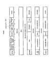
- IEEE 1394 is known as a high-speed serial digital interface that transfers real-time data such as video and audio isochronously and asynchronously transfers control data.
- An overview of IEEE 1394 related standards is shown in FIG.
- a device that executes it secures a channel that is an isochronous resource and a necessary band from an IRM (isochronous resource manager) that exists only on the IEEE 1394 bus by using an IEEE 1394 transaction, and the logic of the transmitting device. This is realized by associating a typical output plug and a logical input plug of the receiving apparatus with channel information. It is defined that when a bus reset occurs, the device that established the connection recovers the connection before the bus reset within 1 second from the bus reset.
- IRM isochronous resource manager
- MPEG2-TS and BT.601 are defined as video (video), and A & M is defined as audio (voice).
- the control command specification on IEEE 1394 is standardized by 1394TA (Trade Association), and AV / C Digital ⁇ ⁇ ⁇ ⁇ Interface Command Set General Specification Version 4.2 ”, AV / C command framework and AV / C unit / sub A unit model is defined.
- the AV / C subunit is a functional unit existing inside the AV / C unit, and a plurality of AV / C subunits may exist in one AV / C unit.
- serial bus isochronous output plug serial bus isochronous output plug
- serial bus isochronous input plug serial plug included in the AV / C unit
- the source plug (destination plug) and the destination plug (destination plug) of the AV / C subunit correspond to the logical output plug and logical input plug of the AV / C subunit.
- CCM AV / C Connection and Compatibility Management Specification 1.0
- AV / C Connection and Compatibility Management Specification 1.0 is defined for establishing a connection on the receiving apparatus side using the AV / C command for the connection of IEC 61883-1.
- a connection between the transmission device and the reception device For example, here, as an example of a car AV system, there are a front monitor (F monitor), a DVD player, an amplifier, a television receiver, and a rear monitor (R monitor), and these devices are connected together via a bus. Suppose that they are connected in a daisy chain.
- F monitor front monitor
- DVD player DVD player
- amplifier amplifier
- television receiver television receiver
- R monitor rear monitor
- a connection for transmitting a video signal and an audio signal from the television receiver to the R monitor is established.
- the video signal transmitted from the DVD player to the F monitor, the audio signal transmitted from the DVD player to the amplifier, the video signal transmitted from the television receiver to the R monitor, and the audio signal are different from each other. Assigned channels.
- Patent Document 1 A method is known in which reservation information (reservation ID and reservation time) and communication resources (channel and bandwidth) are stored in association with each other and connection reservation management is performed based on the information (Patent Document 1).
- Patent Document 1 does not assume a state where the bus is divided, and the problem is different from the present invention.
- An object of the present invention is to provide a control device that can prevent channel contention in a plurality of connection establishment processes that span a plurality of devices.
- a channel associated with a band between the logical output plug of the transmission device and the logical input plug of the reception device connected to the transmission device via a bus. It is a control device in a network system that establishes a connection by connecting, and comprises channel setting means for setting the non-overlapping channels for the output plugs of all the transmitting devices in the network system.
- a channel associated with a band between a logical output plug of a transmitting device and a logical input plug of a receiving device connected to the transmitting device via a bus A transmission device in a network system that establishes a connection by connecting, a non-volatile storage unit that stores channel information indicating the channels that do not overlap in the network system, and the storage unit that stores the channel information at the time of startup Channel setting means for setting the channel as an output plug based on channel information.
- a receiving device in a network system that establishes a connection by connecting, the communication means for communicating with a transmitting device in which the channel that does not overlap in the network system is set as an output plug, and the channel that is set in the output plug And a connection establishment means for establishing a connection with the transmission device.
- a receiving apparatus in a network system for establishing a connection by connecting comprising: nonvolatile storage means for storing channel assignment information in which non-overlapping channels are assigned to all output plugs in the network system.
- a connection establishment for establishing a connection with the transmission device using the channel is obtained based on the channel assignment information and obtaining a channel of an output plug of the transmission device to be the connection target. Means are provided.
- a channel associated with a band between a logical output plug of the transmission device and a logical input plug of the reception device connected to the transmission device via a bus.
- a command receiving means for receiving a connection establishment execution request command to which channel information indicating the non-overlapping channel is added in the network system;
- Connection establishment means for establishing a connection with the transmission device based on the channel information added to the command.
- a channel associated with a band is provided between a logical output plug of the transmission device and a logical input plug of the reception device connected to the transmission device via a bus.
- a network system for connecting and establishing a connection comprising channel setting means for setting the non-overlapping channels for the output plugs of all the transmitting devices connected to the bus.
- a channel associated with a band is provided between a logical output plug of a transmission device and a logical input plug of a reception device connected to the transmission device via a bus.
- a channel associated with a band between a logical output plug of a transmission device and a logical input plug of a reception device connected to the transmission device via a bus A control program executed by a computer in a network system that establishes a connection by connecting the computer as channel setting means for setting the non-overlapping channels for output plugs of all the transmitting devices in the network system. Make it work.
- a logical output plug of a transmission device and a logical input plug of a reception device connected to the transmission device via a bus are connected by a channel associated with a band.
- a channel setting means for setting the non-overlapping channels for the output plugs of all the transmitting devices in the network system.
- the above control device connects the logical output plug of the transmission device and the logical input plug of the reception device connected to the transmission device via a bus by a channel associated with the band. It is a system controller that controls connections in a network system that establishes the connection.
- the control device includes channel setting means.
- the channel setting means sets a non-overlapping channel for the output plugs of all transmission devices in the network system. By doing so, it is possible to prevent the occurrence of contention when establishing a connection.
- output plug recognition means for recognizing output plugs of all the transmission devices connected to the bus, and all detected by the output plug detection means
- Channel assignment information generating means for generating channel assignment information in which non-overlapping channels are assigned to the output plug.
- control device includes a nonvolatile storage unit that stores the channel assignment information generated by the channel assignment information generation unit.
- control device includes channel assignment information notifying means for transmitting the channel assignment information to another control device in the network system.
- channel assignment information can be shared, and new channel assignment information can be generated using the existing channel assignment information also by the other control device.
- a channel information acquisition unit that acquires channel information of an output plug of the transmission device based on the channel assignment information; and the channel information acquired by the channel information acquisition unit.
- Channel information notifying means for transmitting to the transmitting device.
- the transmission device can hold a channel of an output plug that does not overlap with other transmission devices.
- Another aspect of the above control device includes channel assignment information notifying means for transmitting the channel assignment information to the receiving device.
- the receiving apparatus can hold channel assignment information, and can establish a connection with the transmitting apparatus without duplicating channels.
- the control device when the number of channel information of the channel assignment information exceeds an upper limit that can be held, or when a predetermined time has elapsed after the bus reset, it is not connected to the bus Channel information deleting means for deleting the channel information of the output plug of the transmitting apparatus from the channel assignment information. As a result, more channel information of the transmission device connected to the bus can be included in the channel assignment information.
- a logical output plug of a transmission device and a logical input plug of a reception device connected to the transmission device via a bus are connected by a channel associated with a band.
- the transmission device in the network system that establishes the connection in the network system includes a non-volatile storage unit that stores channel information indicating the non-overlapping channels in the network system, and the channel information stored in the storage unit at the time of startup. And channel setting means for setting the channel as an output plug.
- a device that executes connection processing waits for activation of all devices in the network system if the other party of the connection exists on the same bus when the ACC power is turned on.
- a channel is associated with a band between a logical output plug of a transmission device and a logical input plug of a reception device connected to the transmission device via a bus.
- the receiver in the network system that establishes a connection by connecting the communication unit with the transmitter in which the non-overlapping channel is set in the output plug in the network system, and the channel set in the output plug.
- a connection establishment means for establishing a connection with the transmission device.
- a channel is associated with a band between a logical output plug of a transmission device and a logical input plug of a reception device connected to the transmission device via a bus.
- the receiving device in the network system that establishes a connection by connecting non-volatile storage means for storing channel assignment information in which non-overlapping channels are assigned to all output plugs in the network system. Even with this receiving device, if the other party of the connection exists on the same bus when the ACC power is turned on, a channel that does not overlap in the network system without waiting for the activation of all devices in the network system. It is possible to establish a connection using
- a channel of the output plug of the transmitting device to be connected is obtained based on the channel assignment information, and a connection is established with the transmitting device using the channel. Connection establishing means is provided.
- a channel is associated with a band between a logical output plug of a transmission device and a logical input plug of a reception device connected to the transmission device via a bus.
- a receiving device in a network system that establishes a connection by connecting a command connection means for receiving a connection establishment execution request command to which channel information indicating the channel not overlapping in the network system is added; and the connection establishment execution request command Connection establishment means for establishing a connection with the transmission device based on the channel information added to the transmission device. Even with this receiving device, if the other party of the connection exists on the same bus when the ACC power is turned on, a channel that does not overlap in the network system without waiting for the activation of all devices in the network system. It is possible to establish a connection using
- a channel is associated with a band between a logical output plug of a transmission device and a logical input plug of a reception device connected to the transmission device via a bus. And a channel setting means for setting the non-overlapping channels for the output plugs of all the transmitting devices connected to the bus.
- This network system can also prevent occurrence of channel contention when establishing a connection.
- a channel is associated with a band between a logical output plug of a transmission device and a logical input plug of a reception device connected to the transmission device via a bus. And a channel setting step for setting the non-overlapping channels for the output plugs of all the transmitting devices in the network system.
- This control method can also prevent occurrence of channel contention when establishing a connection.
- a channel is associated with a band between a logical output plug of a transmission device and a logical input plug of a reception device connected to the transmission device via a bus.
- the computer is a control program that is executed by a computer in a network system that establishes a connection by connecting, and the computer as channel setting means for setting the non-overlapping channels for output plugs of all the transmission devices in the network system To work. This program can also prevent the occurrence of channel contention when establishing a connection.
- FIG. 3 is a diagram illustrating a configuration example of the car AV system 1 according to the embodiment of the present invention.
- the car AV system 1 includes a front monitor (F monitor) 11, a DVD player 12, an amplifier 13, a car navigation device 14, a DTV (Digital Television) 15, and rear monitors (R monitors) 16 and 17.
- the cables are connected in a daisy chain by cables for the IEEE1394 bus 10a to 10f.
- bus 10 the cables 10a to 10f are described together, they are simply referred to as “bus 10”.
- the F monitor 11 is a video receiving device that displays video on a display based on various video signals received from the video transmitting device.
- the F monitor 11 includes a graphic system controller that controls the F monitor 11 based on a control signal sent from a system controller (control device) or a transmission device via the bus 10, and a memory such as a VRAM (Video RAM).
- the F monitor 11 controls display of liquid crystal, CRT (Cathode Ray Tube), etc. based on a buffer memory that temporarily stores video signals that can be displayed immediately and a video signal output from the graphic system controller.
- a display control unit is composed of a liquid crystal display device having a diagonal size of about 5 to 10 inches, for example, and is mounted near the front panel in the vehicle.
- the DVD player 12 is a video transmission device that reads content data such as an audio signal and a video signal from a disc such as a DVD and transmits the content data to a video reception device. It is also an audio transmission device that transmits to the audio reception device.
- the amplifier 13 is connected to an in-vehicle speaker, and is an audio reception device that outputs audio through the in-vehicle speaker based on various audio signals received from the audio transmission device.
- the amplifier 13 includes a D / A converter that performs D / A (Digital-to-Analog) conversion of an audio signal received via the bus 10, and an amplifier that amplifies an audio analog signal output from the D / A converter.
- the car navigation device 14 uses a GPS (Global Positioning System), a self-supporting positioning device such as a vehicle speed pulse, a gyro, and the like to present the current position and guide the user to the destination when driving the vehicle. Give guidance.
- the car navigation device 14 is a voice transmission device that has a guide voice or the like necessary for guidance, reads a corresponding voice signal, and transmits it to the voice reception device.
- the car navigation device 14 is a video transmission device that holds map data and the like necessary for guidance, reads a corresponding video signal, and transmits the video signal to the video reception device.
- the DTV 15 is a device that receives a television broadcast (for example, terrestrial digital broadcast in Japan) using digital modulation and digital compression.
- the DTV 15 is an audio transmission device that transmits a received audio signal of a television broadcast to an audio reception device.
- the DTV 15 is a video transmission device that transmits a received television broadcast video signal to a video reception device.
- the R monitors 16 and 17 are image receiving devices similar to the F monitor 11, but are mounted on the rear side of the vehicle. In addition, the R monitors 16 and 17 function as an audio receiving device in the same manner as the amplifier 13.
- the F monitor 11, the DVD player 12, and the R monitors 16 and 17 have HMI (Human Machine Interface) such as a touch panel and buttons, and are also used as a system controller for controlling the car AV system 1. Function.
- the system controller basically exists in a monitor or H / U (Head Unit).
- the system controller is the DVD player 12 and the R monitor 16, but the present invention is not limited to this, and an apparatus functioning as the system controller can be arbitrarily set.
- Each system controller can operate independently, and performs device recognition on the network (bus 10), connection management of a device that is operated by itself, and the like. There are a plurality of system controllers on the network that establish connections between the devices.
- the receiving device to be managed by each system controller is determined.
- the F monitor 11 and the amplifier 13 are the receiving devices to be managed by the system controller of the DVD player 12.
- the R monitor 16 is a receiving device to be managed by the system controller of the R monitor 16.
- Each system controller performs device recognition processing, and manages connection control and management between the receiving device and the transmitting device to be managed, and selection source information.
- the selected source information is the currently selected video and audio source type information (digital terrestrial broadcasting, DVD, AM / FM tuner, etc.), and is selected when the next system accessory (ACC) is turned on. The viewing environment based on the type information is restored.
- Each system controller controls connections between devices in accordance with instructions from an application such as a monitor (UI) or a user interface (H / U).
- UI monitor
- H / U user interface
- each process by the system controller, the transmission device, and the reception device described in the present embodiment is realized by executing a program prepared in advance by each CPU of the system controller, the transmission device, and the reception device.
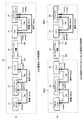
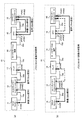
- FIGS. 4 and 5 are schematic diagrams showing an example of an operation state of the car AV system 1 when the ACC power supply of the vehicle is once turned off after being turned on and then turned on again.
- FIG. 4A shows an operation state when the accessory (ACC) power supply is turned on
- FIG. 4B shows the operation state again after the ACC power supply is turned off once.
- the operation state immediately after turning on is shown.
- FIG. 5A shows an operation state immediately after all devices connected to the bus 10 are started and a bus reset occurs
- FIG. 5B shows one second after the bus reset occurs.
- oPCR output Plug Control Register
- iPCR input Plug Control ⁇ ⁇ ⁇ Register
- the system controller of the DVD player 12 selects the DVD player 12 as the video transmission device, the F monitor 11 as the video reception device, the DVD player 12 as the audio transmission device, and the amplifier 13 as the audio reception device. Select.
- the system controller of the DVD player 12 sends a connection establishment request to a device (for example, each receiving device) that executes connection processing, and establishes a connection for transmitting a video signal from the video transmitting device to the video receiving device. And establishing a connection for transmitting a voice signal from the voice transmitting apparatus to the voice receiving apparatus.
- the system controller of the R monitor 16 selects the DTV 15 as the video transmission device and the audio transmission device, and selects the R monitor 16 as the video reception device and the audio reception device.
- the system controller of the R monitor 16 transmits a connection establishment request to a device (for example, each receiving device) that executes connection processing, and transmits a video signal from the video transmitting device to the video receiving device. And a connection for transmitting an audio signal from the audio transmitting device to the audio receiving device is established.
- the device that executes the connection process secures a channel (0 to 63 ch) that is an isochronous resource and a necessary band from the IRM that exists only on the bus 10, and includes an output plug of the transmission device and an input plug of the reception device.
- a connection is established using a reserved channel.
- the channel is associated with a band, and the band depends on the data rate of the video or audio signal output from the transmission apparatus.
- the F monitor 11 has a gap between an output plug oPCR [0] of the DVD player 12 as a video transmission device and an input plug iPCR [0] of the F monitor 11 as a video reception device.
- the connection is established using the channel 32ch.
- the amplifier 13 establishes a connection between the output plug oPCR [1] of the DVD player 12 as an audio transmitting device and the input plug iPCR [0] of the amplifier 13 as an audio receiving device using a channel 33ch.
- the R monitor 16 establishes a connection between the output plug oPCR [0] of the DTV 15 that is the video transmission device and the input plug iPCR [0] of the R monitor 16 that is the video reception device by using the channel 34ch. Further, the R monitor 16 establishes a connection between the output plug oPCR [1] of the DTV 15 serving as the voice transmitting device and the input plug iPCR [1] of the R monitor serving as the voice receiving device using the channel 35ch.
- the device that executes the connection process secures the channel and the necessary bandwidth from the IRM that exists only on the bus 10, and therefore the connections between the devices do not overlap. Established using different channels.
- the state of the ACC power source of the vehicle is detected, and even if the ACC power source is turned off and the power supply of the car AV system 1 is cut off, , Keep selected source information.
- the ACC power supply is turned on and the power supply of the car AV system 1 is resumed, the video that was viewed before the ACC power supply was turned off. This is because the voice needs to be restored as soon as possible.
- the time required for each device to start up varies. For example, in the operation state shown in FIG. 4B, immediately after the ACC power supply is turned on, activation of the car navigation device 14 is delayed, and other devices are activated. In the car AV system 1, since the devices are connected in a daisy chain, if the activation of the car navigation device 14 is delayed, no signal is transmitted via the car navigation device 14, so that as shown in FIG.
- the bus 10 is temporarily divided into buses 10AU and 10BU.
- a channel and a band are secured from the IRM existing on the bus 10AU, and the connection between the video transmission device (DVD player 12) and the video reception device (F monitor 11). Is established on channel 32ch, and a connection between the audio transmitting device (DVD player 12) and the audio receiving device (amplifier 13) is established on channel 33ch.
- a channel and a band are secured from the IRM existing on the bus 10BU, and a connection between the video transmission device (DTV 15) and the video reception device (R monitor 16) is established on the channel 32ch, and audio transmission is performed.
- the connection between the device (DTV 15) and the audio receiving device (R monitor 16) is established on the channel 33ch. That is, in the example shown in FIG. 4B, when the car AV system 1 is viewed as a whole, the channels for transmitting the video signal and the audio signal overlap each other.
- the buses 10AU and 10BU are integrated into one bus 10.
- a bus reset occurs when the car navigation device 14 is activated.
- processing for recovering the connection before the bus reset is performed in the device in which each connection is established in accordance with IEC 61883-1.
- the video signal and the audio signal are transmitted using the channel used before the bus reset. Therefore, the video signal and the audio signal are transmitted in a state where the channels overlap and compete. In this case, different video signals or audio signals are transmitted from a plurality of sources using the same channel, and there is a possibility that the video or audio is broken and cannot be normally reproduced by each receiving apparatus.
- the recovery of one connection in which the conflicting channel is used fails.
- the connection recovery for transmitting the video signal between the DTV 15 and the R monitor 16 has failed.
- the connection recovery of the connection for transmitting the audio signal between the DVD player 12 and the amplifier 13 has failed.
- the connection recovery process is performed in a state where the channels are in contention, there is a possibility that the state of the source when the previous ACC power supply is on cannot be reproduced.
- connection recovery is performed based on the channel before the bus reset, there is a possibility that a connection with the wrong transmission device is established in each reception device.
- non-overlapping channels are assigned to the output plugs of all transmission apparatuses in the car AV system 1.
- one representative system controller (representative system controller) is assigned a non-overlapping channel to the output plugs of all transmission devices in the car AV system 1.
- Generated channel assignment information Then, the device that executes the connection process obtains the channel assigned to the output plug of the transmission device that is the target of the connection process based on the channel assignment information, and establishes the connection using the obtained channel. This will be specifically described below.
- each system controller in the car AV system 1 performs device recognition processing for each device connected to the bus 10 to generate device recognition information.
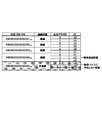
- An example of the device recognition information is shown in FIG.
- the device recognition information includes at least a device unique ID and plug information (plug type, number of plugs) of each device.
- Each system controller generates device recognition information and then stores it in a nonvolatile memory or the like.
- GUID indicates a device unique ID
- oPCR indicates the number of output plugs
- iPCR indicates the number of input plugs.
- GUID is a 64-bit identifier that is stored in a register space called Configuration ROM in a device (node) having IEEE 1394 and allocated to each product.
- the device unique ID may not be “GUID” as long as each device can be identified by an ID that is always unique in the system. According to the device recognition information shown in FIG. 6, it can be seen that the DVD player 12 and the car navigation device 14 each have two output plugs. It can also be seen that the amplifier 13 and the F monitor 11 each have one input plug, and the R monitors 16 and 17 each have two input plugs.
- the device recognition information shown in FIG. 6 it is understood that the memory audio is newly connected to the bus 10 from the external input, and the external input has three output plugs.
- the device recognition information may include detailed function information, video or audio format information, physical connection state information with respect to the bus 10, and the like.
- One representative system controller among the system controllers in the car AV system 1 generates device recognition information and then indicates channel allocation to output plugs of all transmission devices based on the device recognition information. Generate channel assignment information.
- the representative system controller is, for example, a system controller having a maximum or minimum PhyID (ID for identifying a device) on the bus 10.
- the system controller existing in the H / U may always function as the representative system controller.
- “PhyID” is a physical ID that is assigned to each node after a bus reset and changes at each bus reset in IEEE1394.
- the representative system controller generates channel assignment information by assigning channels so as not to overlap with respect to output plugs of all transmission devices connected to the bus 10 based on the device recognition information.
- An example of the channel assignment information is shown in FIG.
- the channel assignment information indicates a channel to be used when establishing a connection for the output plug of each transmission device of the entire system.
- the device unique ID (GUID) of each device, the plug ID of the output plug, and the output It includes at least a channel (ch) assigned to the plug ID.
- “connection state” indicates a physical connection state to the bus 10.
- the timing for generating the channel assignment information is that after the generation of the device recognition after the bus reset is completed, or the representative system controller automatically detects that all devices on the system have been recognized.
- the user may refer to the device recognition information via the UI, and the user may start by user operation when all devices on the system are recognized.
- the channel 32ch is assigned to the output plug oPCR [0], and the channel 33ch is assigned to the output plug oPCR [1].
- channels 34ch and 35ch are assigned to the two output plugs of the car navigation apparatus 14, and channels 36ch and 37ch are assigned to the two output plugs of the DTV 15.
- channels 41ch to 43ch are assigned to three newly added external input plugs. This is because channels 38 ch to 40 ch have already been assigned to unconnected transmission apparatuses that are not currently connected to the bus 10.
- the representative system controller is recognized in the current device recognition process even though it has been registered in the existing channel assignment information when it has already created existing channel assignment information.
- the channel allocated to the transmission apparatus is not deleted, but is included in the new channel allocation information.
- FIG. 8 shows the configuration of the car AV system 1 based on channel assignment information to which channels are assigned in this way.
- the representative system controller extracts the device unique ID of the transmission device and the number of plugs of the output plug from the device recognition information, and copies the existing channel assignment information to the new channel assignment information.
- the representative system controller uses the device unique ID of the transmission device extracted from the device recognition information to search the transmission device for new channel allocation information in which the existing channel allocation information is copied.
- the representative system controller holds the channel already assigned to the output plug of the transmitting device when the transmitting device is already registered as a result of the search for the transmitting device, and when the transmitting device is not registered. Then, a channel that does not overlap with the already assigned channel is set as the output plug of the transmitting apparatus.
- the generation of new channel assignment information is completed.
- the case where the physical connection information here is represented by a structure is, for example, as shown in FIG. 7, for example, after a physical connection state of “connected” is placed first, The channel allocation information in which the physical connection state is “not connected” is arranged.
- the representative system controller extracts the device unique ID of the transmission device and the number of plugs of the output plug from the device recognition information after the bus reset.
- the representative system controller adds all the transmission devices in the device recognition information (that is, connected to the bus 10) in order from the top of the list of new channel assignment information.
- the representative system controller searches for the added transmission device with respect to the existing channel assignment information.
- the representative system controller uses the channel already assigned to the output plug as a new channel of the output plug of the transmission device. Register in the channel assignment information.
- the representative system controller uses a channel that does not overlap with the already assigned channel as a channel of the output plug of the transmission device. Register in the channel assignment information. After the representative system controller registers all the transmission devices in the device identification information in the new channel assignment information, the representative system controller does not exist in the device recognition information (that is, not connected to the bus 10), although it exists in the existing channel assignment information. The transmitting apparatus is copied following the new channel assignment information together with the channels assigned by the existing channel assignment information. This completes the generation of new channel assignment information.
- the representative system controller extracts the device unique ID of the transmitting device and the number of plugs of the output plug from the device recognition information, and sets all the “connection status” of the existing channel assignment information to “unconnected”. Is copied to the new channel assignment information.
- the representative system controller uses the device unique ID extracted from the device recognition information to search the transmission device for new channel assignment information in which the existing channel assignment information is copied. If the representative system controller is a device that has already been registered as a result of the search for the transmitting device, the representative system controller holds the channel already assigned to the output plug and sets the “connection state” to “connected”.
- the representative system controller sets and registers the channel in the output plug so as not to overlap with the already assigned channel and sets the “connection state” to “connected”.
- the representative system controller does not overlap the channels of the output plugs of all the transmission devices existing in the existing channel assignment information. Assign a channel to the output plug of the newly connected transmitter.
- the representative system controller should notify the channel assignment information when the channel assignment information is newly generated, when there is a change in the new channel assignment information compared with the existing channel assignment information, or When a new device appears after the bus reset, the channel assignment information is notified to the device (other system controller or receiving device) to be notified. This is because the channel allocation information is shared, or the device that executes the connection process can refer to the channel allocation information.
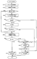
- step S101 the system controller performs a process of acquiring a device unique ID of a device connected to the bus 10 after a bus reset.
- step S102 the system controller acquires device recognition information based on the acquired device unique ID. Thereafter, the system controller proceeds to the process of step S103.
- step S103 if the system controller is a system controller that performs channel assignment, that is, a representative system controller (step S103: Yes), the process proceeds to step S104, and if it is not a representative system controller (step S103: No). Then, the acquired device recognition information is stored in a non-volatile memory or the like, and this control process is terminated.
- step S104 the system controller determines whether or not the channel assignment information is already held, that is, whether or not the existing channel assignment information is present. If the system controller has the existing channel assignment information (step S104: Yes), the system controller proceeds to the process of step S105. On the other hand, if the system controller does not have the existing channel assignment information (step S104: No), the system controller proceeds to the process of step S109 and duplicates the output plugs of all the transmission devices present in the device recognition information. A channel not to be set is set to generate channel assignment information, and the process proceeds to step S110.
- step S105 the system controller compares the device recognition information with the existing channel assignment information, and identifies an unregistered transmission device that is not in the existing channel assignment information among the transmission devices present in the device recognition information.
- step S106 the system controller sets a non-overlapping channel for the output plug of the unregistered transmitting apparatus that is not included in the existing channel assignment information, and generates new channel assignment information. Thereafter, the system controller proceeds to the process of step S107.
- step S107 the system controller determines whether or not channel assignment has been completed for all transmission devices present in the device recognition information. If channel assignment has not been completed (step S107: No), step S107 is performed. Returning to the process of S105, when the channel assignment is completed (step S107: Yes), the process proceeds to step S108.
- step S108 the system controller determines whether or not the generated new channel assignment information has changed as compared with the existing channel assignment information, and if it has changed (step S108: Yes). Then, the process proceeds to step S110. If there is no change (step S108: No), the process proceeds to step S111.
- step S110 the system controller notifies the device to be notified of the new channel assignment information, for example, all the system controllers and receiving devices in the car AV system 1, and then ends this control process.
- step S111 the system controller determines whether or not a device to which channel assignment information is to be notified is newly added based on the device recognition information. If it is determined that the device is newly added (step S111: Yes), The process proceeds to step S110, and if it is determined that no new addition has been made (step S111: No), this control process is terminated.
- channel assignment information generation process shown in FIG. 9 it is possible to generate channel assignment information in which channels that are not duplicated are assigned to the output plugs of all transmission apparatuses in the car AV system 1.
- step S201 the system controller performs a process of acquiring the device unique ID of the device connected to the bus 10 after the bus reset.
- step S202 the system controller performs a process of comparing the existing device recognition information stored in the nonvolatile memory or the like with the acquired device unique ID. Thereafter, the system controller proceeds to the process of step S203.
- step S203 based on the result of the process in step S202, the system controller recognizes a device whose device unique ID is newly recognized that is not in the existing device recognition information (that is, an unrecognized device newly connected to the bus 10). Device) or a device that exists in the existing device recognition information but does not exist in the acquired device unique ID (that is, a device that is not connected to the bus 10) is determined.
- the system controller determines that such a device exists (step S203: Yes)
- the system controller proceeds to the process of step S204.
- step S203: No The control process ends.
- step S204 the system controller acquires device information (including the plug type and the number of plugs) of the unrecognized device, updates the device recognition information, and then proceeds to the process of step S205.
- step S205 if the system controller is a system controller that performs channel assignment, that is, a representative system controller (step S205: Yes), the process proceeds to step S206, and if it is not a representative system controller (step S205: No) ), The acquired device recognition information is stored in a non-volatile memory or the like, and this control process is terminated.
- step S206 the system controller determines whether or not there is a transmission device among unrecognized devices newly connected to the bus 10, or there is a transmission device among devices that are not connected to the bus 10. It is determined whether or not to do so.
- the system controller determines that there is a transmitting device in an unrecognized device newly connected to the bus 10 or a device not connected to the bus 10 (step S206: Yes).
- the process proceeds to step S207.
- step S206: No the process proceeds to step S213.
- step S213 the system controller determines whether or not a device to which channel assignment information is to be notified is newly added based on the device recognition information. If it is determined that the device is newly added (step S213: Yes), The process proceeds to step S212, and if it is determined that no new addition has been made (step S213: No), this control process ends.
- step S207 the system controller determines whether or not it has existing channel assignment information. If the system controller has the existing channel assignment information (step S207: Yes), the system controller proceeds to the process of step S208. On the other hand, if the system controller does not have the existing channel assignment information (step S207: No), the system controller proceeds to the process of step S210 and overlaps with the output plugs of all the transmission devices existing in the device recognition information. A channel not to be set is set to generate channel assignment information, and the process proceeds to step S211.
- step S208 the system controller refers to the existing channel assignment information, and outputs the unrecognized transmission device newly connected to the bus 10 so as not to overlap with the channel registered in the existing channel assignment information. Assign channels to plugs.
- step S209 the system controller connects to the bus 10 in the channel assignment information generated in step S208 if necessary, such as when information indicating the physical connection state is included in the channel assignment information. The connection status information for the transmitting device whose status has changed is updated.
- step S211 the system controller generates new channel assignment information.
- step S212 the system controller notifies the device to be notified of the new channel assignment information, for example, all the system controllers and receiving devices in the car AV system 1, and then ends this control process.
- the car AV system 1 in the case of having existing device recognition information, by assigning a channel only to a newly recognized unrecognized transmission device, the car AV system 1 It is possible to generate channel assignment information in which non-overlapping channels are assigned to the output plugs of all the transmitters.
- the representative system controller keeps assigning a channel to a transmission device not connected to the bus 10 registered in the existing channel assignment information, but the present invention is not limited to this.
- the representative system controller transmits from the channel assignment information unconnected to the bus 10
- the channel information of the device may be deleted.
- the representative system controller when the channel allocation information is represented by a structure as shown in FIG. 7, that is, when a transmitter not connected to the bus 10 is arranged at the rear, It may be deleted from the end of the information.
- the user may confirm the device recognition information from the UI and delete the channel information of the transmission device not connected to the bus 10 from the channel assignment information.
- more channel information of the transmission device connected to the bus 10 can be included in the channel assignment information.
- the representative system controller notifies the device to be notified of the channel assignment information.
- the representative system controller notifies the device to be notified of the generated channel assignment information.
- the devices to be notified are all system controllers and receiving devices in the car AV system 1.
- the reason that the representative system controller notifies the channel assignment information to all the system controllers is that the generated channel assignment information is shared among all the system controllers in the car AV system 1.
- the representative system controller transmits channel assignment information as a channel assignment information setting command to all system controllers.
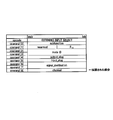
- FIG. 11 shows an example of a channel assignment information setting command format.
- the channel assignment information setting command format shown in FIG. 11 has channel information of output plugs of X transmission apparatuses. As shown in FIG. 11, oPCR [i].
- a channel is set to channel.
- the system controller that has received the channel assignment information setting command stores the received channel assignment information in a nonvolatile memory or the like.
- all the system controllers include the representative system controller itself.
- the notification to the representative system controller itself is an internal process, it goes without saying that the channel assignment information may be stored in the nonvolatile memory internally without notifying the representative system controller as a command.
- channel assignment information can be shared among all system controllers in the car AV system 1. As a result, even when the system controller that functions as the representative system controller is switched, new channel assignment information can be created using the channel assignment information that has already been created, and channel assignment information is created from the beginning. No need to rework.
- connection establishment method Next, a connection establishment method will be described. Specifically, as a connection establishment method, three methods can be considered according to the specification of the system.
- the first connection establishment method will be described.
- channel information assigned to the output plug of each transmission device is held by each transmission device itself, and a device that executes connection processing is held by the transmission device to be connected. Confirm the channel information and establish a connection.
- the representative system controller refers to the generated channel assignment information, acquires channel information assigned to the output plug of each transmission device, and notifies each transmission device. Specifically, the representative system controller sets channel information in the channel field of the output plug oPCR of each transmission device using a lock transaction (lock transaction) defined by IEEE1394.
- FIG. 12 shows the format of the output plug oPCR defined in IEC 61883-1. The representative system controller repeats this operation for all output plugs of all transmission devices. In this way, each transmission device can hold a channel of an output plug that does not overlap with other transmission devices.
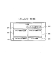
- FIG. 13 shows the configuration of the transmission apparatus when this connection establishment method is used.
- the transmission device stores a transmission control unit 101 that performs data transmission control, a command transmission / reception processing unit 102 that performs command transmission / reception processing with other devices, a transaction management unit 103 that manages transactions during connection processing, and channel information.
- a channel storage unit 104 such as a nonvolatile memory, a channel setting unit 105 for setting a channel to the output plug oPCR, and a plug control unit 106 for controlling the output plug are configured.
- the channel setting unit 105 stores the channel information set in the channel field of the output plug oPCR by the representative system controller in the channel storage unit, and outputs the channel information stored in the channel storage unit 104 when the transmitter is activated. Reset to the channel field of oPCR.
- a device that performs connection processing confirms the channel set in the channel field of the output plug oPCR of the transmitting device when establishing the connection, and secures the set channel from the IRM to establish a connection. Establish.
- connection establishment process at this time will be described with reference to the flowchart of FIG.
- step S301 upon receiving a connection establishment execution request, a device that executes connection processing checks the channel field of the output plug oPCR of the transmission device.
- step S302 the device that executes the connection process determines whether or not a connection has already been established in the output flag of the transmission device.
- step S302: Yes the device that executes the connection process assumes that the channel and the band have already been secured and proceeds to the processing of step S307. If it is determined that the connection has not been established (step S302: No), the process proceeds to step S303.
- step S303 the apparatus that executes the connection process performs a process of securing the channel set in the channel field from the IRM.
- step S304 the apparatus that executes the connection process determines whether or not the channel has been successfully secured from the IRM. If the channel is successfully secured (step S304: Yes), the process proceeds to step S305. If channel securing fails (step S305: No), the process proceeds to step S313.
- step S305 the device that executes the connection process performs a process of securing a bandwidth from the IRM.
- the apparatus that executes the connection process determines whether or not the band is successfully secured from the IRM. If the band is successfully secured (step S306: Yes), the process proceeds to the process of step S307. If the band cannot be secured (step S306: No), the process proceeds to step S312.
- step S307 the apparatus that executes the connection process sets a channel for the process of updating the output plug oPCR of the transmission apparatus and the input plug iPCR of the reception apparatus, that is, the output plug oPCR of the transmission apparatus and the input plug iPCR of the reception apparatus. Perform the process of setting the connection status.
- step S308 the apparatus that executes the connection process determines whether or not the update is successful. If the update is successful (step S308: Yes), the process proceeds to step S309, and the connection establishment request is successful. In response, this control process ends.
- step S308: No the apparatus that executes the connection process proceeds to the process of step S310, and determines whether or not a channel and a band have been secured. If it is determined in step S310 that the device that executes the connection process has secured the channel and band (step S310: Yes), the process proceeds to step S311 and it is determined that the channel and band are not secured. If so (step S310: No), the process proceeds to step S313. In step S311, the device that executes the connection process returns the bandwidth to the IRM. In subsequent step S312, the apparatus that executes the connection process returns the channel to the IRM. Thereafter, the apparatus that executes the connection process proceeds to the process of step S313. In step S313, the apparatus that executes the connection process returns a connection establishment request failure, and ends this control process.
- connection establishment process it is possible to establish a connection when the transmission apparatus itself holds the channel information.
- the apparatus that executes the connection process since the apparatus that executes the connection process establishes the connection by referring to the empty channel from the IRM, all the apparatuses in the car AV system 1 are activated. If a connection is to be established before the connection is established, the channels used for the connection may be duplicated in the car AV system 1.
- the apparatus that executes the connection process establishes a connection using a channel that is set in the output plug of the transmission apparatus and does not overlap in the car AV system 1.
- the second connection establishment method will be described.
- the channel assignment information is held by the reception device, and the reception device establishes a connection with the transmission device by referring to the channel assignment information held by itself.
- the representative system controller notifies the channel assignment information to all receiving devices in advance.
- a method for notifying channel assignment information to all receiving apparatuses will be described with reference to FIGS. 15 and 16 are schematic diagrams showing the relationship among the system controller (SC), the transmission device, and the reception device. 15 and 16, the alternate long and short dash arrows indicate the notification of channel assignment information from the representative system controller to all the system controllers, as described above.
- the representative system controller transmits the channel assignment information setting command shown in FIG. 11 to all receiving apparatuses.
- the channel assignment information can be notified to all receiving apparatuses, and each receiving apparatus can hold the channel assignment information.
- the receiving device that has received the channel assignment information setting command stores the channel assignment information in a nonvolatile memory or the like. Note that the representative system controller does not need to notify the channel assignment information because it is a duplicate notification to the receiving device that also functions as the system controller, as indicated by a one-dot chain line arrow.
- each system controller notifies channel management information to the receiving device managed by each system controller. Specifically, since the channel assignment information has already been notified from the representative system controller to each system controller, as shown by the solid line arrows, each system controller manages the receiving apparatus managed by each system controller as shown in FIG. The channel assignment information setting command shown in FIG. As a result, the channel assignment information can be notified to all receiving apparatuses, and each receiving apparatus can hold the channel assignment information.
- the receiving device that has received the channel assignment information setting command stores the channel assignment information in a nonvolatile memory or the like.
- FIG. 17 shows the configuration of the receiving apparatus when this connection establishment method is used.
- the receiving device includes a reception control unit 201 that performs data reception control, a command transmission / reception processing unit 202 that performs transmission / reception processing of commands with other devices, a transaction management unit 203 that manages transactions during connection processing, and stores channel assignment information.
- a channel allocation information storage unit 204 such as a non-volatile memory, a connection processing execution unit 205 that executes connection processing, and a plug control unit 206 that controls input plugs.
- the channel assignment information storage unit 204 stores channel assignment information received from the representative system controller (or system controller). At the time of establishing a connection, the receiving device refers to the channel assignment information stored in its own channel assignment information storage unit 204, confirms the output plug of the transmitting device to be connected, and determines the output plug of the transmitting device. A channel is secured from the IRM and a connection is established.
- connection establishment process at this time will be described with reference to the flowchart of FIG.
- step S401 when the receiving device receives the connection establishment execution request, the receiving device refers to the channel assignment information of the designated transmitting device stored in the channel assignment information section.
- step S402 the receiving apparatus confirms the output plug of the transmitting apparatus to be connected.
- step S403 the receiving apparatus determines whether or not a connection has already been established in the output flag of the transmitting apparatus.
- step S403: Yes the receiving apparatus determines that the connection has already been established in the output flag of the transmitting apparatus (step S403: Yes)
- step S408 assuming that the channel and band have already been secured, and the connection is established.
- step S404 If it is determined that it has not been established (step S403: No), the process proceeds to step S404.
- step S ⁇ b> 404 the receiving apparatus performs processing for securing the channel of the output plug of the transmitting apparatus confirmed by the channel assignment information from the IRM.
- step S405 the receiving apparatus determines whether or not the channel has been successfully secured from the IRM. If the channel is successfully secured (step S405: Yes), the process proceeds to step S406, and the channel cannot be secured. If so (step S405: No), the process proceeds to step S414.
- step S406 the receiving apparatus performs processing for securing a band from the IRM.
- step S407 the receiving apparatus determines whether or not the band is successfully secured from the IRM. If the band is successfully secured (step S407: Yes), the process proceeds to step S408 to secure the band. When it fails (step S407: No), it progresses to the process of step S413.
- step S408 the receiving apparatus performs a process of updating the output plug oPCR of the transmitting apparatus and the input plug iPCR of the receiving apparatus.
- step S409 the receiving apparatus determines whether or not the update is successful. If the update is successful (step S409: Yes), the process proceeds to step S410, and the connection establishment request success is returned as a response. This control process ends. On the other hand, if the update has failed (step S409: No), the receiving apparatus proceeds to the process of step S411 and determines whether the channel and the band have been secured. If it is determined in step S411 that the receiving apparatus has secured the channel and band (step S411: Yes), the process proceeds to step S412 and if it is determined that the channel and band are not secured.
- Step S411 No
- the process proceeds to Step S414.
- step S412 the receiving apparatus returns the band to the IRM.
- step S413 the receiving apparatus returns the channel to the IRM. Thereafter, the receiving apparatus proceeds to the process of step S414.
- step S414 the receiving apparatus responds with a connection establishment request failure and ends this control process.
- connection establishment process it is possible to establish a connection when all the receiving apparatuses hold channel assignment information. Also, with this connection establishment process, the receiving apparatus waits for activation of all apparatuses in the car AV system 1 if the other party of the connection exists on the same bus when the ACC power is turned on. In addition, it is possible to establish a connection using channels that do not overlap in the car AV system 1.
- the third connection establishment method Describes the third connection establishment method.
- the channel assignment information is held by the system controller, and channel information and channel assignment information are not notified to the transmission device and the reception device.
- the system controller itself executes connection processing, or the system controller adds channel information to the connection establishment execution request command and transmits it to the receiving device, and the receiving device executes connection processing based on the channel information. . This will be specifically described below.
- connection establishment method when the system controller itself executes connection processing will be described.
- FIG. 19 shows the configuration of the system controller when this connection establishment method is used.
- the system controller stores a control unit 301 that controls the entire system controller, a command transmission / reception processing unit 302 that performs transmission / reception processing of commands with other devices, a transaction management unit 303 that manages transactions during connection processing, and channel assignment information
- a channel allocation information storage unit 304 such as a non-volatile memory, a connection processing execution unit 305 that executes connection processing, and a plug control unit 306 that controls input / output plugs. Note that the plug control unit may be omitted if the system controller itself does not have an input or output plug.
- the system controller establishes a connection by referring to the channel assignment information stored in the channel assignment information storage unit 304 and performing a connection process between the receiving apparatus and the arbitrary transmitting apparatus that are managed by the system controller. Specifically, the system controller performs processing similar to the processing performed by the receiving apparatus illustrated in FIG.
- the system controller when the system controller has channel allocation information, the system controller itself can establish a connection.
- connection establishment method in the case where channel information is added to the connection establishment execution request command and transmitted to the receiving apparatus will be described.
- a control command (SIGNAL SOURCE command) that establishes an internal connection by associating an arbitrary source plug of an AV / C subunit existing in an AV / C unit serving as a transmission device with an output plug of the AV / C unit.
- SIGNAL SOURCE command a control command that establishes an internal connection by associating an arbitrary source plug of an AV / C subunit existing in an AV / C unit serving as a transmission device with an output plug of the AV / C unit.
- INPUT SELECT command for establishing an isochronous connection between the output plug of the receiver and the input plug of the receiving device and an internal connection between the input plug of the receiving device and the destination plug of the AV / C subunit in the receiving device.
- FIG. 20 shows the format of the expanded INPUT SELECT command. As shown in FIG. 20, a channel field in which channel information is set is added to the expanded INPUT SELECT command.
- the system controller refers to the channel assignment information at the time of connection establishment execution request, acquires the channel information of the output plug of the transmission device to be connected, and sends the channel information to the connection establishment execution request command. Is transmitted to the receiving device.
- the receiving apparatus that has received the connection establishment execution request command confirms the added channel information, secures the confirmed channel from the IRM, and establishes the connection.
- connection establishment process at this time will be described with reference to the flowchart of FIG.
- step S501 when the receiving device receives the connection establishment execution request command, the receiving device checks the output plug of the transmitting device. In subsequent step S502, the receiving apparatus determines whether or not a connection has already been established in the output flag of the transmitting apparatus. If the receiving apparatus determines that the connection has already been established in the output flag of the transmitting apparatus (step S502: Yes), it proceeds to the process of step S507, assuming that the channel and band have already been secured, and the connection is established. If it is determined that it has not been established (step S502: No), the process proceeds to step S503.
- the reception apparatus refers to the connection establishment execution request command, confirms the channel of the output plug of the transmission apparatus to be connected, and confirms the output plug of the transmission apparatus confirmed by the channel information in the connection establishment request command.
- a process of securing a channel from the IRM is performed.
- steps S504 to S513 is the same as the processing in steps S405 to S414 in FIG.
- the receiving apparatus waits for activation of all apparatuses in the car AV system 1 if the other party of the connection exists on the same bus when the ACC power is turned on. In addition, it is possible to establish a connection using channels that do not overlap in the car AV system 1.
- the representative system controller generates channel allocation information in which channels that do not overlap with the output plug of the transmission device are generated, and based on the generated channel allocation information, A device that executes connection processing establishes a connection. By doing so, there is no channel contention when establishing a connection. Further, by storing the channel assignment information in a non-volatile memory or the like, even when the bus 10 is disconnected when the ACC power is turned off, the channel does not compete at the time of establishing a connection. Also, according to the present embodiment, it is not necessary to wait for all devices to start after the ACC power is turned on.
- the ACC if the connection partner exists on the same bus at the timing when the ACC power is turned off, the ACC The viewing source can be quickly restored before the power is turned off. Further, according to the channel assignment information generation method described in the present embodiment, it is possible to flexibly cope with changes in the system configuration such as addition and deletion of devices.
- a channel that does not overlap with the output plug of the transmission device is set based on the channel assignment information generated by the representative system controller, but the present invention is not limited to this.
- channels that do not overlap in the system are stored in advance in the nonvolatile memory of the transmission device, and the transmission device outputs the stored channels after startup. It may be set to a plug.
- the transmission device when the transmission device is installed in the system, a channel that is not duplicated in the system is assigned by the user, and the transmission device may set the channel assigned by the user as an output plug after activation.
- a device that executes connection processing (for example, a receiving device) establishes a connection by performing processing similar to that shown in FIG.
- the method according to the modification it is not necessary to generate channel assignment information by the representative system controller as compared with the method described in the above embodiment, and the same effect can be obtained by a simple method. That is, there is no channel contention when establishing a connection. Further, by storing the channel assignment information in a non-volatile memory or the like, even when the bus 10 is disconnected when the ACC power is turned off, the channel does not compete at the time of establishing a connection. Also, according to the present embodiment, it is not necessary to wait for all devices to start after the ACC power is turned on. Therefore, if the connection partner exists on the same bus at the timing when the ACC power is turned off, the ACC The viewing source can be quickly restored before the power is turned off.
- the present invention is not limited to the above-described embodiments, and can be appropriately changed without departing from the gist or concept of the invention that can be read from the claims and the entire specification.
- the apparatus and the receiving apparatus are also included in the technical scope of the present invention.
- the present invention can be used for a network system such as a car AV system using an IEEE1394 bus.
Landscapes
- Engineering & Computer Science (AREA)
- Computer Networks & Wireless Communication (AREA)
- Signal Processing (AREA)
- Multimedia (AREA)
- Small-Scale Networks (AREA)
Abstract
Description
10 バス
11 フロントモニター
12 DVDプレイヤー(システムコントローラ)
13 アンプ
14 カーナビゲーション装置
15、16 リアモニター(システムコントローラ)
まず、カーAV(Audio Video)システム1の構成及び前提条件について、図3を用いて説明する。図3は、本発明の実施例に係るカーAVシステム1の構成例を示す図である。
次に、図4、5を用いて、カーAVシステム1の動作例について具体的に説明する。図4、5は、車両のACC電源がオンから一旦オフとなった後、再度オンとなるときのカーAVシステム1の動作状態の一例を示す模式図である。
最初に、チャンネル割当情報の生成方法について説明する。
次に、チャンネル割当情報の通知方法について説明する。先にも述べたように、代表システムコントローラは、通知すべき装置に対し、生成したチャンネル割当情報を通知する。ここで、通知すべき装置とは、カーAVシステム1における全てのシステムコントローラや受信装置である。
次に、コネクション確立方法について説明する。具体的には、コネクション確立方法としては、システムの仕様に応じて、3つの方法が考えられる。
上述の実施例では、代表システムコントローラにて生成されたチャンネル割当情報を基に、送信装置の出力プラグに重複しないチャンネルが設定されるとしているが、これに限られない。このようにする代わりに、システムの構築段階で、予め、システム内で重複しないチャンネルを送信装置の不揮発性メモリなどに記憶させておき、当該送信装置は、起動後に、記憶されていたチャンネルを出力プラグに設定するとしても良い。または、当該送信装置をシステムに設置する際に、ユーザによりシステム内で重複しないチャンネルが割り当てられ、当該送信装置は、起動後に、ユーザにより割り当てられたチャンネルを出力プラグに設定するとしても良い。コネクション処理を実行する装置(例えば受信装置)は、図14に示したのと同様の処理を行うことでコネクションを確立する。
Claims (15)
- 送信装置の論理的な出力プラグと、前記送信装置とバスを介して接続された受信装置の論理的な入力プラグとの間を、帯域と対応づけたチャンネルで結んでコネクションを確立するネットワークシステムにおける制御装置であって、
前記ネットワークシステム内における全ての前記送信装置の出力プラグに対し重複しない前記チャンネルを設定するチャンネル設定手段を備えることを特徴とする制御装置。 - バスリセット後において、前記バスに接続された全ての前記送信装置の出力プラグを認識する出力プラグ認識手段と、
前記出力プラグ検出手段により検出された全ての出力プラグに対し重複しないチャンネルが割り当てられたチャンネル割当情報を生成するチャンネル割当情報生成手段と、を備えることを特徴とする請求項1に記載の制御装置。 - 前記チャンネル割当情報生成手段により生成された前記チャンネル割当情報を記憶する不揮発性の記憶手段を備えることを特徴とする請求項2に記載の制御装置。
- 前記ネットワークシステムにおける他の制御装置に前記チャンネル割当情報を送信するチャンネル割当情報通知手段を備えることを特徴とする請求項2又は3に記載の制御装置。
- 前記チャンネル割当情報に基づいて、前記送信装置の出力プラグのチャンネル情報を取得するチャンネル情報取得手段と、
前記チャンネル情報取得手段により取得された前記チャンネル情報を前記送信装置に送信するチャンネル情報通知手段と、を備えることを特徴とする請求項2乃至4のいずれか一項に記載の制御装置。 - 前記チャンネル割当情報を前記受信装置に送信するチャンネル割当情報通知手段を備えることを特徴とする請求項2乃至5のいずれか一項に記載の制御装置。
- 前記チャンネル割当情報のチャンネル情報の数が保持可能な上限を超えた場合、又は、バスリセット後に所定の時間が経過した場合には、前記バスに未接続の送信装置の出力プラグのチャンネル情報を前記チャンネル割当情報より削除するチャンネル情報削除手段を備えることを特徴とする請求項2乃至6のいずれか一項に記載の制御装置。
- 送信装置の論理的な出力プラグと、前記送信装置とバスを介して接続された受信装置の論理的な入力プラグとの間を、帯域と対応づけたチャンネルで結んでコネクションを確立するネットワークシステムにおける送信装置であって、
前記ネットワークシステム内において重複しない前記チャンネルを示すチャンネル情報を記憶する不揮発性の記憶手段と、
起動時において、前記記憶手段に記憶された前記チャンネル情報を基に、前記チャンネルを出力プラグに設定するチャンネル設定手段と、を備えることを特徴とする送信装置。 - 送信装置の論理的な出力プラグと、前記送信装置とバスを介して接続された受信装置の論理的な入力プラグとの間を、帯域と対応づけたチャンネルで結んでコネクションを確立するネットワークシステムにおける受信装置であって、
前記ネットワークシステム内において重複しない前記チャンネルが出力プラグに設定された送信装置と通信を行う通信手段と、
前記出力プラグに設定された前記チャンネルを用いて、前記送信装置とコネクションを確立するコネクション確立手段と、を備えることを特徴とする受信装置。 - 送信装置の論理的な出力プラグと、前記送信装置とバスを介して接続された受信装置の論理的な入力プラグとの間を、帯域と対応づけたチャンネルで結んでコネクションを確立するネットワークシステムにおける受信装置であって、
前記ネットワークシステム内における全ての出力プラグに対し重複しないチャンネルが割り当てられたチャンネル割当情報を記憶する不揮発性の記憶手段を備えることを特徴とする受信装置。 - 前記チャンネル割当情報に基づいて、前記コネクションの対象となる前記送信装置の出力プラグのチャンネルを求め、当該チャンネルを用いて、前記送信装置とコネクションを確立するコネクション確立手段を備えることを特徴とする請求項10に記載の受信装置。
- 送信装置の論理的な出力プラグと、前記送信装置とバスを介して接続された受信装置の論理的な入力プラグとの間を、帯域と対応づけたチャンネルで結んでコネクションを確立するネットワークシステムにおける受信装置であって、
前記ネットワークシステム内において重複しない前記チャンネルを示すチャンネル情報が付加されたコネクション確立実行要求コマンドを受信するコマンド受信手段と、
前記コネクション確立実行要求コマンドに付加された前記チャンネル情報を基に、前記送信装置とコネクションを確立するコネクション確立手段と、を備えることを特徴とする受信装置。 - 送信装置の論理的な出力プラグと、前記送信装置とバスを介して接続された受信装置の論理的な入力プラグとの間を、帯域と対応づけたチャンネルで結んでコネクションを確立するネットワークシステムであって、
前記バスに接続された全ての前記送信装置の出力プラグに対し重複しない前記チャンネルを設定するチャンネル設定手段を備えることを特徴とするネットワークシステム。 - 送信装置の論理的な出力プラグと、前記送信装置とバスを介して接続された受信装置の論理的な入力プラグとの間を、帯域と対応づけたチャンネルで結んでコネクションを確立するネットワークシステムにおける制御装置により実行される制御方法であって、
前記ネットワークシステム内における全ての前記送信装置の出力プラグに対し重複しない前記チャンネルを設定するチャンネル設定工程を備えることを特徴とする制御方法。 - 送信装置の論理的な出力プラグと、前記送信装置とバスを介して接続された受信装置の論理的な入力プラグとの間を、帯域と対応づけたチャンネルで結んでコネクションを確立するネットワークシステムにおけるコンピュータにより実行される制御プログラムであって、
前記ネットワークシステム内における全ての前記送信装置の出力プラグに対し重複しない前記チャンネルを設定するチャンネル設定手段、として前記コンピュータを機能させる制御プログラム。
Priority Applications (3)
| Application Number | Priority Date | Filing Date | Title |
|---|---|---|---|
| JP2011511222A JP5149440B2 (ja) | 2009-04-28 | 2009-04-28 | 制御装置、ネットワークシステム、送信装置、受信装置、制御方法及び制御プログラム |
| US13/266,363 US20120044952A1 (en) | 2009-04-28 | 2009-04-28 | Control device, network system, transmitting device, receiving device, control method and control program |
| PCT/JP2009/058406 WO2010125655A1 (ja) | 2009-04-28 | 2009-04-28 | 制御装置、ネットワークシステム、送信装置、受信装置、制御方法及び制御プログラム |
Applications Claiming Priority (1)
| Application Number | Priority Date | Filing Date | Title |
|---|---|---|---|
| PCT/JP2009/058406 WO2010125655A1 (ja) | 2009-04-28 | 2009-04-28 | 制御装置、ネットワークシステム、送信装置、受信装置、制御方法及び制御プログラム |
Publications (1)
| Publication Number | Publication Date |
|---|---|
| WO2010125655A1 true WO2010125655A1 (ja) | 2010-11-04 |
Family
ID=43031822
Family Applications (1)
| Application Number | Title | Priority Date | Filing Date |
|---|---|---|---|
| PCT/JP2009/058406 Ceased WO2010125655A1 (ja) | 2009-04-28 | 2009-04-28 | 制御装置、ネットワークシステム、送信装置、受信装置、制御方法及び制御プログラム |
Country Status (3)
| Country | Link |
|---|---|
| US (1) | US20120044952A1 (ja) |
| JP (1) | JP5149440B2 (ja) |
| WO (1) | WO2010125655A1 (ja) |
Families Citing this family (2)
| Publication number | Priority date | Publication date | Assignee | Title |
|---|---|---|---|---|
| KR102576159B1 (ko) * | 2016-10-25 | 2023-09-08 | 삼성디스플레이 주식회사 | 표시 장치 및 이의 구동 방법 |
| US10542476B2 (en) * | 2017-07-13 | 2020-01-21 | Nokia Solutions And Networks Oy | Selecting communication paths for application server queries of devices |
Citations (4)
| Publication number | Priority date | Publication date | Assignee | Title |
|---|---|---|---|---|
| JP2001127776A (ja) * | 1999-10-29 | 2001-05-11 | Sony Corp | 電子機器および接続方式設定方法 |
| JP2001285295A (ja) * | 2000-03-29 | 2001-10-12 | Matsushita Electric Ind Co Ltd | デジタルデータ送受信装置 |
| JP2002319992A (ja) * | 2001-04-23 | 2002-10-31 | Matsushita Electric Ind Co Ltd | 接続管理方法および接続管理ノード |
| JP2004096167A (ja) * | 2002-08-29 | 2004-03-25 | Matsushita Electric Ind Co Ltd | デジタルインタフェース搭載機器 |
Family Cites Families (6)
| Publication number | Priority date | Publication date | Assignee | Title |
|---|---|---|---|---|
| US7383341B1 (en) * | 1996-10-15 | 2008-06-03 | Kabushiki Kaisha Toshiba | Data transfer control device, relay device and control device suitable for home network environment |
| JP3277874B2 (ja) * | 1998-01-29 | 2002-04-22 | 日本電気株式会社 | Ieee1394ブリッジ |
| KR100662484B1 (ko) * | 1999-08-23 | 2007-01-02 | 엘지전자 주식회사 | 디지털 인터페이스에서의 버스 제어방법 |
| JP4166956B2 (ja) * | 2001-01-12 | 2008-10-15 | パイオニア株式会社 | データ伝送システム、コネクション確立方法及び情報伝送装置 |
| JP2003199092A (ja) * | 2001-12-28 | 2003-07-11 | Sony Corp | 表示装置および制御方法、プログラムおよび記録媒体、並びに表示システム |
| JP4082237B2 (ja) * | 2003-02-21 | 2008-04-30 | ソニー株式会社 | 通信方法及び通信装置 |
-
2009
- 2009-04-28 JP JP2011511222A patent/JP5149440B2/ja not_active Expired - Fee Related
- 2009-04-28 WO PCT/JP2009/058406 patent/WO2010125655A1/ja not_active Ceased
- 2009-04-28 US US13/266,363 patent/US20120044952A1/en not_active Abandoned
Patent Citations (4)
| Publication number | Priority date | Publication date | Assignee | Title |
|---|---|---|---|---|
| JP2001127776A (ja) * | 1999-10-29 | 2001-05-11 | Sony Corp | 電子機器および接続方式設定方法 |
| JP2001285295A (ja) * | 2000-03-29 | 2001-10-12 | Matsushita Electric Ind Co Ltd | デジタルデータ送受信装置 |
| JP2002319992A (ja) * | 2001-04-23 | 2002-10-31 | Matsushita Electric Ind Co Ltd | 接続管理方法および接続管理ノード |
| JP2004096167A (ja) * | 2002-08-29 | 2004-03-25 | Matsushita Electric Ind Co Ltd | デジタルインタフェース搭載機器 |
Also Published As
| Publication number | Publication date |
|---|---|
| US20120044952A1 (en) | 2012-02-23 |
| JP5149440B2 (ja) | 2013-02-20 |
| JPWO2010125655A1 (ja) | 2012-10-25 |
Similar Documents
| Publication | Publication Date | Title |
|---|---|---|
| US20090077492A1 (en) | Address list updating apparatus and method for updating address list | |
| US8774594B2 (en) | Controlled information processing apparatus | |
| KR102798022B1 (ko) | 전자 장치 및 그 동작방법 | |
| JP2015167318A (ja) | 通信システムおよび電子装置、ペアリング方法、ペアリングプログラム | |
| JP2001103408A (ja) | 情報出力装置および接続関係管理方法 | |
| US20130321124A1 (en) | Control device, under-control device, control method thereof, remote control system, and recording medium | |
| US20120311644A1 (en) | Communication apparatus, communication method, and communication system | |
| JP5149440B2 (ja) | 制御装置、ネットワークシステム、送信装置、受信装置、制御方法及び制御プログラム | |
| US20160248653A1 (en) | Main electronic device for communicating within a network and method for operating a main electronic device for communicating within the network | |
| US6732262B1 (en) | Method and system for controlling reset of IEEE 1394 network | |
| US20240049350A1 (en) | Electronic apparatus and operating method thereof | |
| JP6033186B2 (ja) | 携帯端末装置 | |
| JP3501707B2 (ja) | 情報処理装置及び情報処理システム及びそれらの方法 | |
| JP2008278164A (ja) | 通信システム | |
| JP4961496B2 (ja) | 情報処理装置、受信装置、送信装置、制御装置及び制御プログラム | |
| JP5050098B2 (ja) | 制御装置、制御方法、制御プログラム及びネットワークシステム | |
| JPH1117717A (ja) | 通信方法、及び通信システム | |
| US20120209938A1 (en) | Master device, map table update method, program, and recording medium | |
| WO2009128162A1 (ja) | 送信装置、制御方法及び制御プログラム | |
| CN119421111A (zh) | 控制设备、智能设备配网方法及计算机可读存储介质 | |
| WO2009128159A1 (ja) | 送信装置、受信装置、制御方法及びネットワークシステム | |
| JP2002064884A (ja) | 情報制御方法、情報処理装置および情報制御システム | |
| JP2014233019A (ja) | 情報処理装置及びコンピュータプログラム | |
| JP2003078537A (ja) | 機器認識方法及び電子機器 | |
| JP2012070231A (ja) | 映像音声中継表示装置およびその制御方法、集積回路 |
Legal Events
| Date | Code | Title | Description |
|---|---|---|---|
| 121 | Ep: the epo has been informed by wipo that ep was designated in this application |
Ref document number: 09843999 Country of ref document: EP Kind code of ref document: A1 |
|
| DPE2 | Request for preliminary examination filed before expiration of 19th month from priority date (pct application filed from 20040101) | ||
| ENP | Entry into the national phase |
Ref document number: 2011511222 Country of ref document: JP Kind code of ref document: A |
|
| WWE | Wipo information: entry into national phase |
Ref document number: 13266363 Country of ref document: US |
|
| NENP | Non-entry into the national phase |
Ref country code: DE |
|
| 122 | Ep: pct application non-entry in european phase |
Ref document number: 09843999 Country of ref document: EP Kind code of ref document: A1 |