WO2010117049A1 - ミキサー用アタッチメント、ミキサー用アタッチメントを使用するパン製造方法、ミキサー用アタッチメントを使用するパン生地製造方法、及び回転駆動装置 - Google Patents
ミキサー用アタッチメント、ミキサー用アタッチメントを使用するパン製造方法、ミキサー用アタッチメントを使用するパン生地製造方法、及び回転駆動装置 Download PDFInfo
- Publication number
- WO2010117049A1 WO2010117049A1 PCT/JP2010/056408 JP2010056408W WO2010117049A1 WO 2010117049 A1 WO2010117049 A1 WO 2010117049A1 JP 2010056408 W JP2010056408 W JP 2010056408W WO 2010117049 A1 WO2010117049 A1 WO 2010117049A1
- Authority
- WO
- WIPO (PCT)
- Prior art keywords
- bread
- attachment
- blade
- rotation
- mixer
- Prior art date
- Legal status (The legal status is an assumption and is not a legal conclusion. Google has not performed a legal analysis and makes no representation as to the accuracy of the status listed.)
- Ceased
Links
Images








Classifications
-
- A—HUMAN NECESSITIES
- A47—FURNITURE; DOMESTIC ARTICLES OR APPLIANCES; COFFEE MILLS; SPICE MILLS; SUCTION CLEANERS IN GENERAL
- A47J—KITCHEN EQUIPMENT; COFFEE MILLS; SPICE MILLS; APPARATUS FOR MAKING BEVERAGES
- A47J43/00—Implements for preparing or holding food, not provided for in other groups of this subclass
- A47J43/04—Machines for domestic use not covered elsewhere, e.g. for grinding, mixing, stirring, kneading, emulsifying, whipping or beating foodstuffs, e.g. power-driven
- A47J43/07—Parts or details, e.g. mixing tools, whipping tools
- A47J43/08—Driving mechanisms
- A47J43/085—Driving mechanisms for machines with tools driven from the lower side
-
- A—HUMAN NECESSITIES
- A21—BAKING; EDIBLE DOUGHS
- A21B—BAKERS' OVENS; MACHINES OR EQUIPMENT FOR BAKING
- A21B7/00—Baking plants
- A21B7/005—Baking plants in combination with mixing or kneading devices
-
- A—HUMAN NECESSITIES
- A47—FURNITURE; DOMESTIC ARTICLES OR APPLIANCES; COFFEE MILLS; SPICE MILLS; SUCTION CLEANERS IN GENERAL
- A47J—KITCHEN EQUIPMENT; COFFEE MILLS; SPICE MILLS; APPARATUS FOR MAKING BEVERAGES
- A47J27/00—Cooking-vessels
- A47J27/004—Cooking-vessels with integral electrical heating means
Definitions
- the present invention relates to a mixer attachment, a bread manufacturing method using the mixer attachment, a bread dough manufacturing method using the mixer attachment, and a rotation driving device.
- a commercial household automatic bread maker puts a bread container containing bread-making ingredients into a baking chamber in the main body, kneads and kneads the bread-making ingredients in the bread container with a kneading blade, and after undergoing a fermentation process,
- the bread container is used as a baking mold to bake bread.
- An example of an automatic bread maker can be seen in Patent Document 1.
- the present invention has been made in view of the above points, and by rotating a grinding blade at high speed inside a bread container with the help of an apparatus (typically a mixer) different from an automatic bread machine,
- the object is to solve the problem of producing bread directly from the grain.
- the present invention is an attachment that is attached to the mixer body in place of the original pulverization container, and has an upper part of a bread container support part for attaching a bread container of an automatic bread maker.
- a rotation transmission unit is provided for transmitting the rotation of the driving shaft on the mixer body side to the blade mounting shaft on the bread container side.
- the rotation transmitting unit outputs the blade to the blade mounting shaft without reducing the rotation of the driving shaft, and reduces the rotation of the driving shaft to reduce the rotation of the driving shaft. It is characterized in that it can be switched between when output to the mounting shaft side.
- the rotation of the driving shaft of the mixer body can be transmitted to the blade mounting shaft without decelerating, or the rotation of the driving shaft of the mixer body can be decelerated and transmitted to the blade mounting shaft. It is possible to rotate both the blade mounting shaft attached with the high speed and the blade mounting shaft attached with the kneading blade at low speed and high torque. Can be used for both.
- the present invention also includes a step of attaching the attachment having the above structure to the mixer body, a step of attaching a bread container of an automatic bread maker to the attachment, a step of attaching a grinding blade to the blade attachment shaft, and a grain grain in the bread container.
- a step of rotating the crushing blade in the mixture of the cereal grains and the liquid to crush the cereal grains, and a baking chamber of the automatic bread maker And a step of replacing the pulverizing blade with a kneading blade, and a step of operating the automatic bread maker to sequentially perform a kneading step, a fermentation step, and a baking step. It is said.
- the bread container is attached to the automatic bread machine body, and the kneading process, fermentation process, and baking process are advanced. Since it is a thing, it can be baked into bread without taking out the grain put in the bread container. For this reason, unlike the method in which grain grains are crushed in another container and then transferred to a bread container, there is no loss associated with the transfer in which the crushed grain grains remain attached to other containers.
- the present invention also includes a step of attaching the attachment having the above structure to the mixer body, a step of attaching a bread container of an automatic bread maker to the attachment, a step of attaching a grinding blade to the blade attachment shaft, and a grain grain in the bread container.
- the bread dough can be manufactured using a mixer, for example, an automatic bread maker performs a fermentation or baking process using a spare bread container while the fermentation process or baking process is being performed. Can improve the bread production efficiency. Moreover, as long as the bread container and the attachment are obtained, the bread can be easily baked from the grain by the procedure of pulverizing the grain and making it into dough with a mixer and then baking the bread in an oven.
- the rotational drive device of the present invention includes a driving shaft, a bread container support portion to which a bread container of an automatic bread maker is attached, and rotation of the driving shaft attached to the bread container support portion. And a rotation transmitting portion for transmitting to the blade mounting shaft of the bread container.
- the driving shaft may be included in a drive unit
- the bread container support unit and the rotation transmission unit may be included in an attachment detachable from the drive unit.
- the rotation transmitting unit outputs the rotation to the blade mounting shaft side without reducing the rotation of the driving shaft, and reduces the rotation of the driving shaft to the blade mounting shaft side. It is good also as being provided so that switching is possible.
- the grinding blade mounting shaft on the bread container side can be rotated by the driving shaft of the mixer body or the rotational drive device, if the grinding blade is attached to the blade mounting shaft, the grinding blade can be rotated at high speed.
- the bread ingredients can be produced by crushing the grain.
- bread can be baked using hand-held grains, eliminating the need to purchase grain flour.
- rice bread can be baked with rice of the desired degree of milling, from brown rice to white rice.
- the bread making raw material is kneaded and fermented without being taken out of the bread container by setting the bread container in an automatic bread making machine.
- the baked grains remain attached to the other containers and can be transferred. There is no loss.
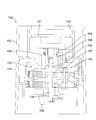
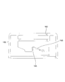
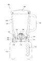
- FIG. 1 It is the front view of the state where the bread container was attached to the mixer body via the attachment, and represents the attachment and the bread container in cross section 1 is a front view similar to FIG. 1, showing a state in which the pulverizing blade is replaced with a kneading blade.
- Vertical section of attachment A vertical sectional view of the attachment showing a state different from FIG.
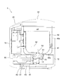
- FIG. 7 the left side of the drawing is the front (front) side of the automatic bread maker 1, and the right side of the drawing is the back (rear) side of the automatic bread maker 1.
- the automatic bread machine 1 has a box-shaped main body 10 composed of a synthetic resin outer shell.
- An operation unit 20 is provided on the front surface of the main body 10.
- the operation unit 20 has operation keys such as a selection key for bread types (wheat flour bread, rice flour bread, bread with ingredients, etc.), a selection key for cooking contents, a timer key, a start key, a cancel key, and the like.
- a display unit is provided for displaying the group and the set cooking contents and timer reservation time.
- the upper surface of the main body behind the operation unit 20 is covered with a synthetic resin lid 30.
- the lid 30 is attached to an edge on the back side of the main body 10 with a hinge shaft (not shown), and rotates in a vertical plane with the hinge shaft as a fulcrum.
- a firing chamber 40 is provided inside the main body 10.
- the baking chamber 40 is made of sheet metal and has an open top surface, from which a bread container 50 is placed.
- the firing chamber 40 includes a peripheral side wall 40a having a rectangular horizontal cross section and a bottom wall 40b that closes the bottom of the peripheral side wall 40a.
- a base 12 made of sheet metal is installed inside the main body 10.
- a bread container support 13 made of an aluminum alloy die-cast product is fixed at a location corresponding to the center of the firing chamber 40. The inside of the bread container support part 13 is exposed inside the baking chamber 40.
- a driving shaft 14 is vertically supported at the center of the bread container support portion 13.
- the lower end of the driving shaft 14 protrudes from the lower surface of the bread container support 13 and a pulley 15 is fixed thereto.
- the bread container support unit 13 supports the bread container 50 by receiving a cylindrical pedestal 51 fixed to the bottom surface of the bread container 50.
- the pedestal 51 is also an aluminum alloy die cast product.
- the bread container 50 is made of sheet metal and has a bucket-like shape, and a handle (not shown) for handbags is attached to the mouth edge.
- the horizontal section of the bread container 50 is a rectangle with rounded corners.
- a kneading blade 52 shown in FIG. 7 or a crushing blade 70 shown in FIG. 1 is arranged at the center of the bottom of the bread container 50.
- a blade mounting shaft 53 to which the kneading blade 52 or the crushing blade 70 is attached is vertically supported after a countermeasure against sealing is applied to the center of the bread container 50.
- the kneading blade 52 or the pulverizing blade 70 is attached to the non-circular cross section at the upper end of the blade attachment shaft 53 by simple fitting and can be attached and detached without using a tool. Therefore, it can be easily replaced with a different kind of kneading blade 52 or grinding blade 70.
- the blade mounting shaft 53 is connected to the driving shaft 14 to transmit power.
- a coupling member 54 is fixed to the lower end of the blade mounting shaft 53, and a coupling member 55 connected to the coupling member 54 is fixed to the upper end of the driving shaft 14.
- a protrusion (not shown) is formed on the inner peripheral surface of the bread container support 13 and the outer peripheral surface of the pedestal 51, respectively.
- These protrusions constitute a well-known bayonet connection. That is, when the bread container 50 is attached to the bread container support part 13, the bread container 50 is lowered so that the protrusions of the base 51 do not interfere with the protrusions of the bread container support part 13, and the base 51 fits into the bread container support part 13. Thereafter, when the bread container 50 is twisted horizontally, the protrusion of the pedestal 51 is engaged with the lower surface of the protrusion of the bread container support portion 13 so that the bread container 50 cannot be pulled upward. By this operation, the coupling member 54 and the coupling member 55 are configured to be simultaneously connected. The twisting direction when the bread container 50 is attached coincides with the rotation direction of the kneading blade 52 so that the bread container 50 does not come off even when the kneading blade 52 rotates.
- the heating device 41 disposed inside the baking chamber 40 surrounds the bread container 50 and heats the bread-making material.
- the heating device 41 is constituted by a sheathed heater.
- a motor 60 is attached to the base 12.
- the motor 60 is a saddle shaft, and an output shaft 61 projects from the lower surface thereof.
- a pulley 62 is fixed to the output shaft 61, and the pulley 62 is connected to the pulley 15 of the driving shaft 14 by a belt 63.
- the pulley 62 Since the driving shaft 14 rotates the kneading blade 52, it is required to rotate at low speed and high torque. Therefore, the pulley 62 has a diameter ratio between the pulleys so that the pulley 15 rotates at a reduced speed.
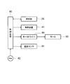
- the operation control of the automatic bread maker 1 is performed by the control device 80 shown in FIG.
- the control device 80 is configured by a circuit board disposed at an appropriate location in the main body 10 (preferably a location that is not easily affected by the heat of the baking chamber 40).
- the motor driver 64 of the motor 60 is provided in addition to the operation unit 20 and the heating device 41.
- the temperature sensor 81 is connected.
- the temperature sensor 81 is disposed in the baking chamber 40 and detects the temperature of the baking chamber 40.
- a commercial power supply 82 supplies power to each component.
- the mixer 100 includes a mixer main body 110 and a pulverization container 120 mounted thereon as main components.
- the mixer body 110 has a known configuration in which a motor 111 (see FIG. 10) is housed in a synthetic resin outer shell.
- an operation unit 112 including a group of operation keys such as a speed selection key and a start / stop key is provided.
- a driving shaft 113 that projects the rotation of the motor 111 to a grinding blade (described later) in the grinding container protrudes upward.
- a coupling member 114 is fixed to the driving shaft 113, and an annular wall 115 that surrounds the coupling member 114 is formed on the upper surface of the mixer body 110.
- the main components of the crushing container 120 are a cup 121 molded from transparent glass or synthetic resin, and a base 122 made of synthetic resin that is coupled to the bottom of the cup 121 by screwing.
- the bottom of the cup 121 is missing, and the upper surface of the pedestal 122 is exposed in the cup 121.
- a crushing shaft 124 having a crushing blade 123 fixed to the upper end is vertically supported with a countermeasure against sealing.
- a coupling member 125 connected to the coupling member 114 is fixed to the lower end of the grinding shaft 124.
- a handle 126 is integrally formed with the cup 121, and the grinding container 120 can be transported by grasping the handle.
- the skirt portion 127 on the outer periphery of the base 122 covers the annular wall 115 from the outside, and the annular rib 128 formed on the inner side of the skirt portion 127 has the inner periphery of the annular wall 115.
- the crushing container 120 is tightly positioned on the mixer body 110.
- coupling between the coupling member 114 and the coupling member 125 is also achieved. If food is put in the cup 121, the cup 121 is covered with the lid 129, and the motor 111 is driven, the mixer 100 can perform a normal crushing operation.
- the operation control of the mixer 100 is performed by the control device 130 shown in FIG.
- the control device 130 is configured by a circuit board disposed at an appropriate position in the mixer main body 110, and the operation unit 112 and the motor driver 116 of the motor 111 are connected to each other.
- 131 is a commercial power source for supplying power to each component.
- the attachment 150 has a shape in which a selector ring 152 capable of relative rotation in a horizontal plane with respect to the main body 151 is superimposed on a cylindrical main body 151 fitted to the annular wall 115.
- a rotation transmission device (rotation transmission unit) 153 is provided inside the main body 151.
- the rotation transmission device 153 includes a transmission shaft 154 supported perpendicularly to the center of the main body 151 and a reduction device (deceleration unit) 155 surrounding the transmission shaft 154.
- a coupling member 156 having the same structure as the coupling member 125 of the crushing container 120 is fixed to the lower end of the transmission shaft 154, and this is connected to the coupling member 114, so that the transmission shaft 154 has the same speed as the driving shaft 113. Rotate.
- Rotation of the transmission shaft 154 is also transmitted to the reduction gear 155.
- the reduction gear 155 has a general configuration using a planetary gear mechanism, and rotation after deceleration appears as rotation of a claw wheel 157 arranged outside the transmission shaft 154.
- the upper end of the transmission shaft 154 enters the cylindrical shaft 158.
- the transmission shaft 154 does not move up and down with respect to the main body 151, the cylinder shaft 158 can move up and down within a certain range with respect to the main body 151, and is always pushed up to the ascending limit position by the compression coil spring 159.
- a claw wheel 160 that meshes with the claw wheel 157 is formed at the lower end of the cylindrical shaft 158.
- an engaging portion (not shown) is formed between the cylinder shaft 158 and the transmission shaft 154 so that direct coupling occurs when the cylinder shaft 158 reaches the rising limit position shown in FIG. 1 or FIG. Yes.
- This engaging portion can be realized by, for example, a spline structure.
- a coupling member 161 connected to the coupling member 54 on the bread container 50 side is fixed to the upper end of the cylindrical shaft 158.
- the selector ring 152 has a bread container support 162 that receives the pedestal 51 of the bread container 50 at the center thereof.
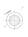
- a cam 163 shown in FIG. 5 is formed on the inner surface of the selector ring 152.
- the cam 163 has a pin 165 (see FIG. 5) that protrudes radially from the outer surface of the ring 164 that is attached to the outer surface of the cylindrical shaft 158 so as to be rotatable with respect to the cylindrical shaft 158 and not vertically movable with respect to the cylindrical shaft 158.
- the ring 164 does not rotate with respect to the main body 151.
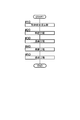
- FIG. 11 is an overall flowchart of the first aspect bread manufacturing process.
- the process proceeds in the order of impregnation process before grinding # 10, grinding process # 20, kneading process # 30, fermentation process # 40, and firing process # 50. Then, the content of each process is demonstrated.
- step # 11 the attachment 150 is attached to the mixer 100 in place of the pulverization container 120.
- step # 12 the bread container 50 is attached to the attachment 150.
- the cylinder shaft 158 of the attachment 150 is placed in the raised position so that the rotation of the transmission shaft 154 is directly transmitted. Thereby, the rotation of the driving shaft 113 is transmitted to the blade mounting shaft 53 without deceleration.
- step # 13 the grinding blade 70 is mounted on the blade mounting shaft 53. This will be in the state shown in FIG. In FIG. 1, the members involved in the power transmission from the driving shaft 113 to the blade mounting shaft 53 to the grinding blade 70 are hatched.
- the user weighs the grain and puts a predetermined amount in the bread container 50 in step # 14.
- Rice grains are most easily available as grains, but other grains such as wheat, barley, straw, buckwheat, buckwheat, corn and the like can also be used.
- step # 15 the user measures the liquid and puts a predetermined amount into the bread container 50.
- a common liquid is water, but it may be a liquid having a taste component such as broth or fruit juice. Alcohol may be contained. Note that the order of step # 14 and step # 15 may be interchanged.
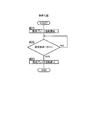
- Step # 16 begins from this point.
- step # 16 the grain and liquid mixture is allowed to stand in the bread container 50, and the grain is impregnated with the liquid.
- step # 17 the control device 130 checks how much time has elapsed since the start of the resting of the grain and liquid.
- the pre-grinding impregnation step # 10 ends. This may be notified to the user by display on the operation unit 112, voice, or the like.
- the pulverization step # 20 shown in FIG. 13 is performed.
- the start key on the operation unit 112 pulverization is started.
- step # 21 the control device 130 drives the motor 111.
- the rotation of the driving shaft 113 is transmitted to the blade mounting shaft 53 without deceleration, and the pulverizing blade 70 rotates at a high speed when the mixer 100 performs pulverization.
- the grinding blade 70 grinds the grain in a mixture of grain and liquid.
- the pulverization by the pulverization blade 70 is performed in a state in which the liquid is immersed in the cereal grains, so that the cereal grains can be easily pulverized to the core.
- the control device 130 checks whether or not the set pulverization pattern has been completed. When the set pulverization pattern is completed, the process proceeds to step # 23 to finish the rotation of the pulverization blade 70, and the pulverization step # 20 is completed. This may be notified to the user by display on the operation unit 112, voice, or the like.
- the pulverization step # 20 is started by the user's operation. However, after the impregnation step # 10 before pulverization ends, the pulverization step # 20 is automatically performed. It may be configured to be started.
- step # 30 the bread container 50 is removed from the attachment 150 and mounted on the automatic bread maker 1.
- the lid 56 is removed.
- the crushing blade 70 is replaced with the kneading blade 52 in step # 32. This will be in the state shown in FIG.
- a series of steps from kneading to baking are performed in the automatic bread maker 1 by operating predetermined keys on the operation unit 20.
- the cereal grains and liquid in the bread container 50 are pasty or slurry dough raw materials.
- the material at the start of the kneading step # 30 is referred to as “dough raw material”, and the material that has approached the intended state of the dough as the kneading progresses is “dough” even in a semi-finished state. It shall be called.
- step # 33 the user opens the lid 30 and puts a predetermined amount of gluten into the dough material. Add seasoning ingredients such as salt, sugar and shortening as needed.
- the user inputs the type of bread and cooking details from the operation unit 20 before and after Step # 33.
- the start key when the preparation is complete, the bread making operation that automatically continues from the kneading step # 30 to the fermentation step # 40 and further to the baking step # 50 is started.
- step # 34 the control device 80 drives the motor 60. Then, the kneading blade 52 starts rotating in the dough material. As described above, since the rotation of the motor 60 is transmitted to the driving shaft 14 while being decelerated, the rotation of the kneading blade 52 is of low speed and high torque.
- the controller 80 energizes the heating device 41 while driving the motor 60 to raise the temperature of the firing chamber 40.
- the kneading blade 52 rotates, the dough raw material is kneaded and kneaded into a dough connected to one having a predetermined elasticity.
- an element of “kneading” is added to the kneading.
- step # 35 the control device 80 checks how much time has elapsed since the start of the rotation of the kneading blade 52. When the predetermined time has elapsed, the process proceeds to step # 36. In step # 36, the user opens the lid 30 and puts yeast into the dough. In step # 37, the control device 80 checks how much time has passed since the yeast was added to the dough. When the time necessary to obtain the desired dough has elapsed, the process proceeds to step # 38, and the rotation of the kneading blade 52 is completed. At this point, the dough that is connected and has the required elasticity has been completed.
- yeast used in step # 36 may be dry yeast. Baking powder may be used instead of yeast.
- step # 41 the dough that has undergone the kneading step # 30 is placed in a fermentation environment. That is, the control device 80 energizes the heating chamber 40 to the heating device 41 if necessary, and sets the temperature in a temperature zone where fermentation proceeds. The user arranges the dough, if necessary, and leaves the dough.
- step # 42 the control device 80 checks how much time has passed since the dough was placed in the fermentation environment. If predetermined time passes, fermentation process # 40 will be complete
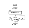
- step # 51 the fermented dough is placed in a baking environment. That is, the control device 80 sends electric power necessary for baking to the heating device 41 and raises the temperature of the baking chamber 40 to the baking temperature zone.
- step # 52 the control device 80 checks how much time has passed since the dough was placed in the baking environment.
- the firing step # 50 ends.
- the user since the completion of bread making is notified by display or sound on the operation unit 20, the user opens the lid 30 and takes out the bread container 50.
- FIG. 17 is an overall flowchart of the second aspect bread manufacturing process.
- the process proceeds in the order of pulverization step # 20, post-pulverization impregnation step # 60, kneading step # 30, fermentation step # 40, and firing step # 50.
- the post-grinding impregnation step # 60 can be performed with the bread container 50 mounted on the mixer main body 110, or can be performed with the bread container 50 mounted on the automatic bread maker 1.
- the content of the post-grinding impregnation step # 60 will be described based on FIG.
- step # 61 the dough raw material formed in the pulverization step # 20 is allowed to stand inside the bread container 50. This dough raw material has not been subjected to the impregnation step before pulverization. While standing still, liquid soaks into the ground grain.
- the control device 80 energizes the heating device 41 as necessary to heat the dough raw material and promote the impregnation. Can do.
- step # 62 the control device 80 checks how much time has passed since the start of standing. When the predetermined time has elapsed, the post-grinding impregnation step # 60 is finished. When the post-grinding impregnation step # 60 is completed, the process proceeds to the kneading step # 30.
- the steps after the kneading step # 30 are the same as the first aspect bread making step.
- FIG. 19 is an overall flowchart of the third aspect bread manufacturing process.
- the pre-pulverization impregnation step # 10 of the first aspect is placed before the pulverization step # 20
- the post-pulverization impregnation step 60 of the second aspect is placed after the pulverization step # 20.
- the steps after the kneading step 30 are the same as the first aspect bread making step.
- the kneading step # 30 is performed on the side of the automatic bread maker 1.
- the setting of the attachment 150 is changed, that is, the decelerated rotation via the decelerator 155 is transmitted to the cylinder shaft 158.
- the crushing blade 70 is replaced with the kneading blade 52, the kneading step # 30 can be performed in the bread container 50 attached to the mixer body 110.
- the selector ring 152 is rotated, and the cylindrical shaft 158 is lowered as shown in FIG. 2 to engage the claw wheel 160 with the claw wheel 157.
- the direct connection between the transmission shaft 154 and the cylinder shaft 158 is disconnected, and the reduced speed rotation via the reduction gear 155 is transmitted to the cylinder shaft 158.
- the members involved in the power transmission from the driving shaft 113 to the blade mounting shaft 53 to the kneading blade 52 are hatched.
- the pulverization blade 70 is replaced with the kneading blade 52, and a predetermined amount of gluten and seasoning materials such as salt, sugar and shortening are added to the dough material as necessary.
- a predetermined amount of gluten and seasoning materials such as salt, sugar and shortening are added to the dough material as necessary.
- the blade mounting shaft 53 rotates at the rotation speed during kneading, and the kneading blade 52 receives the dough raw material in the same manner as when rotating in the automatic bread maker 1. Knead and knead.
- the bread dough can be manufactured using the mixer 100, for example, while the automatic bread maker 1 is performing the fermentation process or the baking process, the bread dough waiting for fermentation / baking is prepared using the spare bread container 50. Can be produced, and the production efficiency of bread is improved.
- the process of pulverizing the grain into bread dough is performed with the mixer 100, and then the bread is baked in an oven, whereby the bread can be easily baked from the grain. it can.
- the attachment 150 is attached to the mixer main body 110 .
- the attachment of the present invention is not limited to the mixer body, and may be widely attached to a drive unit having a driving shaft.
- the mixer main body 110 is one of the embodiments of the drive unit having the driving shaft of the present invention.
- the rotation drive device (device which rotates the blade attachment shaft 53 of the bread container 50.
- Reference numeral 200 corresponds to an embodiment of the rotary drive device
- the speed reducer 155 when it is set as the apparatus for exclusive use of the grinding
- the configuration of the rotation transmission unit is not limited to that of the bread container without decelerating the rotation of the driving shaft. It is necessary to be able to switch between the case where the transmission is transmitted to the blade mounting shaft and the case where the rotation of the driving shaft is decelerated and transmitted to the blade mounting shaft of the bread container.
- pan container support part 162 which attaches the bread container 50 of the automatic bread maker 1, and the blade attachment axis
- the rotation transmitting portion 153 that transmits to 53 is included in the detachable attachment 150.
- This configuration is convenient because it can be used by attaching it to a drive unit (mixer body) that is easily available at home, such as a mixer, and when the drive unit fails, an attachment is attached to an alternative drive unit. There are also merits such as being.
- the scope of the present invention is not limited to this. That is, a configuration in which the bread container support portion and the rotation transmission portion are incorporated in one device (rotation drive device) together with the driving shaft is also included in the scope of the present invention.
- the rotation drive device in this case is configured as either a dedicated grinding device for grinding grain grains or a dedicated device used for grinding grain grains and kneading dough raw materials.
- the speed reduction device 155 as shown in the present embodiment may not be provided.
- the configuration of the rotation transmission unit needs to be the above-described switching configuration.
- the crushing blade 70 can be rotated at high speed inside the bread container 50 with the help of a device prepared separately from the automatic bread maker 1, and bread is produced directly from the grain. It becomes possible to do. Moreover, it becomes possible to manufacture bread dough using a rotation drive device different from the automatic bread maker 1. For example, while the automatic bread maker 1 is performing a fermentation process or a baking process, a spare bread container 50 is used. Can be used to produce bread dough that is ready for fermentation and baking. That is, the bread production efficiency can be improved. In addition, by preparing this rotary drive device, the process from crushing grain into bread dough is performed with this rotary drive device, and then the bread is easily baked in the procedure of baking in the oven. You can also.
- the present invention can be widely used for bread making work in general households.
Landscapes
- Engineering & Computer Science (AREA)
- Food Science & Technology (AREA)
- Life Sciences & Earth Sciences (AREA)
- Mechanical Engineering (AREA)
- Baking, Grill, Roasting (AREA)
- Food-Manufacturing Devices (AREA)
Abstract
自動製パン機1のパン容器50は、本来の粉砕容器120に代えてミキサー本体110に取り付けられるアタッチメント150を介してミキサー本体110に取り付けることができる。アタッチメント150は、パン容器50を取り付けるパン容器支持部162を上部に有し、内部には、ミキサー本体110側の原動軸113の回転をパン容器50側のブレード取付軸53に伝達する回転伝達装置153が設けられている。ブレード取付軸53に粉砕ブレード70を取り付けておけば、パン容器50の内部で穀物粒を粉砕することが可能となる。
Description
本発明は、ミキサー用アタッチメント、ミキサー用アタッチメントを使用するパン製造方法、ミキサー用アタッチメントを使用するパン生地製造方法、及び回転駆動装置に関する。
市販の家庭用自動製パン機は、製パン原料を入れたパン容器を本体内の焼成室に入れ、パン容器内の製パン原料を混練ブレードで混練して捏ね上げ、発酵工程を経た後、パン容器をそのままパン焼き型としてパンを焼き上げる仕組みのものが一般的である。特許文献1に自動製パン機の一例を見ることができる。
パンを製造する場合、これまでは、小麦や米などの穀物を製粉した粉や、それに各種補助原料を混ぜたミックス粉を入手するところから始めなければならなかった。手元に穀物粒(典型的なものは米)があっても、それから直接パンを製造することは困難であった。この問題に対処するため、パン容器の内部に粉砕ブレードを設け、パン容器内で穀物粒を粉砕して製パン原料とすることが考えられているが、混練ブレードと異なり粉砕ブレードは高速回転が必要であり、高速回転のための機構を本体内にどのように設置するかという問題に直面する。
本発明は上記の点に鑑みなされたものであって、自動製パン機とは別の装置(代表例はミキサー)の助けを借りてパン容器の内部で粉砕ブレードを高速回転させることにより、穀物粒から直接パンを製造するという課題を解決することを目的とする。
上記目的を達成するために本発明は、本来の粉砕容器に代えてミキサー本体に取り付けられるアタッチメントであって、自動製パン機のパン容器を取り付けるパン容器支持部を上部に有し、内部には前記ミキサー本体側の原動軸の回転を前記パン容器側のブレード取付軸に伝達する回転伝達部が設けられていることを特徴としている。
上記構成のアタッチメントをミキサー本体に取り付け、このアタッチメントに自動製パン機のパン容器を取り付けると、ミキサー本体側の原動軸の回転がパン容器側のブレード取付軸に伝達される。これにより、ミキサーで用いられる高速回転がパン容器のブレード軸にも適用されることになり、ブレード軸に粉砕ブレードを取り付けておけば、パン容器の内部で穀物粒を粉砕することが可能となる。
また本発明は、上記構成のミキサーのアタッチメントにおいて、前記回転伝達部は、前記原動軸の回転を減速しないで前記ブレード取付軸側に出力する場合と、前記原動軸の回転を減速して前記ブレード取付軸側に出力する場合と、を切替可能に設けられていることを特徴としている。
この構成によると、ミキサー本体の原動軸の回転を減速しないでブレード取付軸に伝達することもできれば、ミキサー本体の原動軸の回転を減速してブレード取付軸に伝達することもできるから、粉砕ブレードを取り付けたブレード取付軸を高速回転させることと、混練ブレードを取り付けたブレード取付軸を低速高トルクで回転させることの両立が可能となり、ミキサーの動力を穀物粒の粉砕と粉砕穀物粒の混練の両方に役立てることができる。
また本発明は、上記構成のアタッチメントをミキサー本体に取り付けるステップと、前記アタッチメントに自動製パン機のパン容器を取り付けるステップと、前記ブレード取付軸に粉砕ブレードを取り付けるステップと、前記パン容器に穀物粒と液体を入れるステップと、前記穀物粒と液体の混合物の中で前記粉砕ブレードを回転させ、前記穀物粒を粉砕するステップと、粉砕穀物粒の入った前記パン容器を自動製パン機の焼成室に取り付けるステップと、前記粉砕ブレードを混練ブレードに交換するステップと、前記自動製パン機を運転し、混練工程、発酵工程、及び焼成工程を順次遂行させるステップを含むパン製造方法であることを特徴としている。
この構成によると、ミキサー本体にアタッチメントを介して取り付けたパン容器の中で穀物粒を粉砕した後、パン容器を自動製パン機本体に取り付けて混練工程、発酵工程、及び焼成工程を進めて行くものであるから、パン容器に入れた穀物粒を外に出すことなくパンに焼き上げることができる。このため、他の容器内で穀物粒を粉砕してからパン容器に移す方式と異なり、粉砕穀物粒が他の容器に付着して残るという、移し替えに伴うロスが発生しない。
また本発明は、上記構成のアタッチメントをミキサー本体に取り付けるステップと、前記アタッチメントに自動製パン機のパン容器を取り付けるステップと、前記ブレード取付軸に粉砕ブレードを取り付けるステップと、前記パン容器に穀物粒と液体を入れるステップと、前記穀物粒と液体の混合物の中で前記粉砕ブレードを回転させ、前記穀物粒を粉砕するステップと、前記粉砕ブレードを混練ブレードに交換するステップと、前記パン容器の粉砕穀物粒を前記混練ブレードで混練し、捏ね上げるステップと、を含むパン生地製造方法であることを特徴としている。
この構成によると、ミキサーを利用してパン生地を製造できるから、例えば自動製パン機が発酵工程や焼成工程を行っている間に予備のパン容器を使用して発酵・焼成待ちのパン生地を製造することができ、パンの製造能率が向上する。また、パン容器とアタッチメントさえ入手すれば、穀物粒を粉砕しパン生地とするまでの工程をミキサーで行い、その後オーブンでパンを焼くといった手順で、手軽に穀物粒からパンを焼き上げることができる。
また上記目的を達成するために、本発明の回転駆動装置は、原動軸と、自動製パン機のパン容器を取り付けるパン容器支持部と、前記原動軸の回転を、前記パン容器支持部に取り付けられた前記パン容器のブレード取付軸に伝達する回転伝達部と、を備えることを特徴としている。
この回転駆動装置に自動製パン機のパン容器を取り付けると、原動軸の回転がパン容器側のブレード取付軸に伝達される。このため、ブレード軸に粉砕ブレードを取り付けておけば、原動軸を高速回転させることにより、パン容器の内部で穀物粒を粉砕することが可能となる。
上記構成の回転駆動装置において、前記原動軸は駆動部に含まれ、前記パン容器支持部と前記回転伝達部とは、前記駆動部に着脱可能なアタッチメントに含まれることとしてもよい。本構成によれば、例えば駆動部が故障したような時に、アタッチメントを別の駆動部に取り付けて使用できる等のメリットがある。
また、上記構成の回転駆動装置において、前記回転伝達部は、前記原動軸の回転を減速しないで前記ブレード取付軸側に出力する場合と、前記原動軸の回転を減速して前記ブレード取付軸側に出力する場合と、を切替可能に設けられていることとしてもよい。
この構成によると、粉砕ブレードを取り付けたブレード取付軸を高速回転させることと、混練ブレードを取り付けたブレード取付軸を低速高トルクで回転させることの両立が可能となり、回転駆動装置によって穀物粒の粉砕と粉砕穀物粒の混練を行うことが可能となる。
本発明によると、パン容器側のブレード取付軸をミキサー本体の原動軸、或いは、回転駆動装置で回転させることができるから、ブレード取付軸に粉砕ブレードを取り付けておけば、粉砕ブレードを高速回転させ、穀物粒を粉砕して製パン原料を製造することができる。このため、手持ちの穀物粒を用いてパンを焼き上げることができ、穀物粉を買い求める必要がなくなる。米の場合で言えば、玄米から白米まで、好みの精白度の米でパンを焼くことができる。そしてパン容器に入れた穀物粒を粉砕ブレードで粉砕して製パン原料とした後は、パン容器を自動製パン機にセットすることにより、製パン原料をパン容器から出すことなく混練、発酵、焼成と工程を進めて行くことができるから、他の容器内で穀物粒を粉砕してからパン容器に移す方式と異なり、粉砕穀物粒が他の容器に付着して残るという、移し替えに伴うロスが発生しない。
最初に、本発明の構成要素であるパン容器を含む自動製パン機の構造を図7に基づき説明する。図7において、図の左側が自動製パン機1の正面(前面)側、図の右側が自動製パン機1の背面(後面)側である。
自動製パン機1は合成樹脂製の外殻により構成される箱形の本体10を有する。本体10の上面前部には操作部20が設けられる。操作部20には、図示は省略するが、パンの種類(小麦粉パン、米粉パン、具材入りパンなど)の選択キー、調理内容の選択キー、タイマーキー、スタートキー、取り消しキーなどといった操作キー群と、設定された調理内容やタイマー予約時刻などを表示する表示部が設けられている。
操作部20から後ろの本体上面は合成樹脂製の蓋30で覆われる。蓋30は図示しない蝶番軸で本体10の背面側の縁に取り付けられており、その蝶番軸を支点として垂直面内で回動する。
本体10の内部には焼成室40が設けられる。焼成室40は板金製で、上面が開口しており、ここからパン容器50が入れられる。焼成室40は水平断面矩形の周側壁40aと周側壁40aの底部を閉ざす底壁40bを備える。
本体10の内部には板金製の基台12が設置されている。基台12には、焼成室40の中心にあたる箇所に、アルミニウム合金のダイキャスト成型品からなるパン容器支持部13が固定されている。パン容器支持部13の内部は焼成室40の内部に露出している。
パン容器支持部13の中心には、原動軸14が垂直に支持されている。原動軸14の下端はパン容器支持部13の下面から突き出し、そこにプーリ15が固定されている。パン容器支持部13は、パン容器50の底面に固定された筒状の台座51を受け入れてパン容器50を支える。台座51もアルミニウム合金のダイキャスト成型品である。
パン容器50は板金製で、バケツのような形状をしており、口縁部には手提げ用のハンドル(図示せず)が取り付けられている。パン容器50の水平断面は四隅を丸めた矩形である。パン容器50の底部中心には、図7に示す混練ブレード52または図1に示す粉砕ブレード70が配置される。混練ブレード52または粉砕ブレード70を取り付けるブレード取付軸53が、パン容器50の中心にシール対策を施した上で垂直に支持されている。
混練ブレード52または粉砕ブレード70は、ブレード取付軸53の上端の非円形断面部に、単なるはめ込みで取り付けられるものであり、工具を用いることなく着脱することができる。このため、異なる種類の混練ブレード52または粉砕ブレード70に容易に交換可能である。
ブレード取付軸53は原動軸14に連結されて動力を伝達される。これを実現するため、ブレード取付軸53の下端にはカップリング部材54が固定され、原動軸14の上端にはカップリング部材54に連結するカップリング部材55が固定されている。
パン容器支持部13の内周面と台座51の外周面には、それぞれ図示しない突起が形成される。これらの突起は周知のバヨネット結合を構成する。すなわちパン容器50をパン容器支持部13に取り付ける際、台座51の突起がパン容器支持部13の突起に干渉しないようにしてパン容器50を下ろし、台座51がパン容器支持部13にはまり込んだ後、パン容器50を水平にひねると、パン容器支持部13の突起の下面に台座51の突起が係合して、パン容器50が上方に抜けなくなる。この操作で、カップリング部材54とカップリング部材55の連結も同時に達成されるように構成されている。パン容器50の取り付け時ひねり方向は混練ブレード52の回転方向に一致させ、混練ブレード52が回転してもパン容器50が外れないようにしておく。
焼成室40の内部に配置された加熱装置41がパン容器50を包囲し、製パン原料を加熱する。加熱装置41はシーズヒータにより構成される。
基台12にはモータ60が取り付けられる。モータ60は竪軸であって、その下面からは出力軸61が突出する。出力軸61にはプーリ62が固定され、プーリ62は原動軸14のプーリ15にベルト63で連結する。
原動軸14は混練ブレード52を回転させるものであるため、低速・高トルクの回転が求められる。そのため、プーリ62はプーリ15を減速回転させるようにプーリ同士の直径比が設定されている。
自動製パン機1の動作制御は、図9に示す制御装置80によって行われる。制御装置80は本体10内の適所(焼成室40の熱の影響を受けにくい箇所が望ましい)に配置された回路基板により構成され、操作部20及び加熱装置41の他、モータ60のモータドライバ64と、温度センサ81が接続される。温度センサ81は焼成室40内に配置され、焼成室40の温度を検知する。82は各構成要素に電力を供給する商用電源である。
次に、本発明の構成要素であるミキサー本体を含むミキサーの構造を図8に基づき説明する。ミキサー100はミキサー本体110とその上に載置される粉砕容器120を主な構成要素としている。
ミキサー本体110は、合成樹脂製の外殻の中にモータ111(図10参照)を収納した、周知の構成のものである。ミキサー本体110の正面には速度選択キーやスタート/ストップキーなどの操作キー群を備えた操作部112が設けられる。ミキサー本体110の上面中央にはモータ111の回転を粉砕容器の中の粉砕ブレード(後述)に伝える原動軸113が上向きに突出している。原動軸113にはカップリング部材114が固定され、ミキサー本体110の上面には、カップリング部材114を囲い込む環状壁115が形成されている。
粉砕容器120の主たる構成要素は、透明なガラスや合成樹脂で成型されたカップ121と、カップ121の底部にねじ込みで結合される合成樹脂製の台座122である。カップ121は底が抜けており、カップ121内には台座122の上面が露出している。台座122の中心には、上端に粉砕ブレード123を固定した粉砕軸124が、シール対策を施した上で垂直に支持されている。粉砕軸124の下端にはカップリング部材114に連結するカップリング部材125が固定されている。
カップ121にはハンドル126が一体成形されており、これを握って粉砕容器120を運搬することができる。粉砕容器120をミキサー本体110の上面に置くと、台座122の外周のスカート部127が環状壁115に外側から被さるとともに、スカート部127の内側に形成された環状リブ128が環状壁115の内周に嵌合し、粉砕容器120はミキサー本体110の上にぴったりと位置決めされる。同時に、カップリング部材114とカップリング部材125の連結も達成される。カップ121の中に食材を入れ、蓋129でカップ121に蓋をして、モータ111を駆動すれば、ミキサー100に通常の粉砕動作を行わせることができる。
ミキサー100の動作制御は、図10に示す制御装置130によって行われる。制御装置130はミキサー本体110内の適所に配置された回路基板により構成され、操作部112と、モータ111のモータドライバ116が接続されている。131は各構成要素に電力を供給する商用電源である。
次に、パン容器50をミキサー本体110に取り付けるため、粉砕容器120に代えてミキサー本体110に設置されるアタッチメント150の構造を、図1から図6までの図を参照しつつ説明する。
アタッチメント150は、環状壁115に嵌合する筒型の本体151の上に、本体151に対し水平面内での相対回転が可能なセレクタリング152を重ねた形状となっている。本体151の内部には回転伝達装置(回転伝達部)153が設けられる。回転伝達装置153は、本体151の中心に垂直に支持された伝達軸154と、それを囲む減速装置(減速部)155により構成される。伝達軸154の下端には、粉砕容器120のカップリング部材125と同じ構造のカップリング部材156が固定され、これがカップリング部材114に連結することにより、伝達軸154は原動軸113と同一速度で回転する。
伝達軸154の回転は減速装置155にも伝えられる。減速装置155は遊星歯車機構を利用した一般的な構成のものであり、減速後の回転は伝達軸154の外側に配置された爪車157の回転として表れる。
伝達軸154の上端は筒軸158の中に入り込む。伝達軸154は本体151に対し上下しないが、筒軸158は本体151に対し一定範囲で上下可能となっており、常時は圧縮コイルばね159により上昇限界位置まで押し上げられている。筒軸158の下端には爪車157にかみ合う爪車160が形成されている。また筒軸158と伝達軸154の間には、筒軸158が図1または図3に示す上昇限界位置に達したとき、直接的な連結が生じる係合部(図示せず)が形成されている。この係合部は、例えばスプライン構造により実現できる。筒軸158の上端には、パン容器50側のカップリング部材54に連結するカップリング部材161が固定されている。
セレクタリング152は、その中央に、パン容器50の台座51を受け入れるパン容器支持部162を有する。セレクタリング152の内面には図5に示すカム163が形成されている。カム163には、筒軸158の外面に筒軸158に対し回転自在、且つ筒軸158に対し上下不能に取り付けられたリング164の外面から放射方向に突出するピン165(図5参照)が係合する。リング164は本体151に対しても回転しない。
セレクタリング152を水平面内で45°回転させると、前述の通りリング164が本体151に対し回転しないことから、カム163がピン165を押し下げ、これにより、リング164を介して筒軸158が押し下げられることになる。セレクタリング152を逆方向に45°回転させると、圧縮コイルばね159の力により、筒軸158とリング164は上昇位置に復帰する。
図2または図4に示すように筒軸158を押し下げると、伝達軸154と筒軸158の間の直接的な連結は外れる。その代わり、筒軸158の下端の爪車160が爪車157にかみ合い、筒軸158には減速装置155を経由した減速回転が伝達されることになる。
セレクタリング152を回動させ、カム163による筒軸158の押し下げを解除すると、図1または図3に示すように圧縮コイルばね159の力で筒軸158は上昇する。これにより、爪車160が爪車157から外れ、筒軸158と減速装置155の連結は解除される。それに代わり、伝達軸154と筒軸158の間の直接的な連結が復活する。
続いて、自動製パン機1、ミキサー100、及びアタッチメント150を用いて穀物粒からパンを製造する工程を、図11から図19までの図を参照しつつ説明する。
図11は第1態様パン製造工程の全体フローチャートである。図11では、粉砕前含浸工程#10、粉砕工程#20、混練工程#30、発酵工程#40、焼成工程#50の順で工程が進行する。続いて、各工程の内容を説明する。
図12に示す粉砕前含浸工程#10では、まずステップ#11において、ミキサー100に粉砕容器120に代えてアタッチメント150を装着する。ステップ#12ではアタッチメント150にパン容器50を装着する。アタッチメント150の筒軸158は上昇位置に置き、伝達軸154の回転が直接伝わるようにしておく。これにより、原動軸113の回転が減速なしでブレード取付軸53に伝達されることになる。ステップ#13ではブレード取付軸53に粉砕ブレード70を装着する。これで図1に示す状態となる。図1では、原動軸113からブレード取付軸53まで、粉砕ブレード70への動力伝達に関与する部材にハッチングが施されている。
上記のように、パン容器50の中で粉砕を行う準備を整えた上で、ステップ#14において、使用者が穀物粒を計量し、所定量をパン容器50に入れる。穀物粒としては米粒が最も入手しやすいが、それ以外の穀物、例えば小麦、大麦、粟、稗、蕎麦、とうもろこしなどの粒も利用可能である。
ステップ#15では使用者が液体を計量し、所定量をパン容器50に入れる。液体として一般的なのは水であるが、だし汁のような味成分を有する液体でもよく、果汁でもよい。アルコールを含有していてもよい。なおステップ#14とステップ#15は順序が入れ替わっても構わない。
パン容器50に穀物粒と液体を入れ終わったら、パン容器50に蓋56をかぶせる。ここで使用者は操作部112の中の所定の操作キーを押し、液体含浸のタイムカウントをスタートさせる。この時点からステップ#16が始まる。ステップ#16では穀物粒と液体の混合物をパン容器50内で静置し、穀物粒に液体を含浸させる。
ステップ#17では穀物粒と液体の静置を開始してからどれだけ時間が経過したかを制御装置130がチェックする。所定時間が経過したら粉砕前含浸工程#10は終了する。このことが、操作部112における表示や、音声などで使用者に報知されるようにしておくとよい。
粉砕前含浸工程#10に続き、図13に示す粉砕工程#20が遂行される。使用者が操作部112でスタートキーを押すと、粉砕が開始される。
ステップ#21では、制御装置130がモータ111を駆動する。原動軸113の回転は減速無しでブレード取付軸53に伝えられ、粉砕ブレード70はミキサー100で粉砕を行う際の高速回転で回転する。粉砕ブレード70は穀物粒と液体の混合物の中で穀物粒を粉砕する。粉砕ブレード70による粉砕は、穀物粒に液体が浸み込んだ状態で行われるから、穀物粒を芯まで容易に粉砕することができる。
なお、操作部112の中の特定のキーを押すと、原動軸113が設定された粉砕パターン(粉砕ブレードを連続回転させるか、停止期間を織り交ぜて断続回転させるか、断続回転させる場合、どのようにインターバルをとるか、回転時間の長さをどのようにするか等)で回転するようにしておいてもよい。その場合は、ステップ#22で、設定通りの粉砕パターンが完遂されたかどうかを制御装置130がチェックする。設定通りの粉砕パターンが完遂されたらステップ#23に進んで粉砕ブレード70の回転を終了し、粉砕工程#20は終了する。このことが、操作部112における表示や、音声などで使用者に報知されるようにしておくとよい。
以上の説明では、粉砕前含浸工程#10の後、使用者の操作で粉砕工程#20が開始されるものとしたが、粉砕前含浸工程#10の終了後、自動的に粉砕工程#20が開始されるように構成してもよい。
粉砕工程#20に続き、図14に示す混練工程#30が遂行される。まずステップ#31において、パン容器50をアタッチメント150から取り外し、自動製パン機1に装着する。蓋56は取り外しておく。続いてステップ#32で粉砕ブレード70を混練ブレード52に交換する。これで図7に示す状態となる。以後、操作部20で所定のキーを操作することにより、混練から焼成までの一連の工程が自動製パン機1において遂行される。
混練工程#30に入る時点では、パン容器50の中の穀物粒と液体は、ペースト状またはスラリー状の生地原料となっている。本明細書では、混練工程#30の開始時点のものを「生地原料」と呼称し、混練が進行して目的とする生地の状態に近づいたものは、半完成状態であっても「生地」と呼称することとする。
ステップ#33では使用者が蓋30を開け、生地原料に所定量のグルテンを投入する。必要に応じ、食塩、砂糖、ショートニングといった調味材料も投入する。
使用者は、ステップ#33に前後して、操作部20よりパンの種類や調理内容の入力を行う。準備が整ったところで使用者がスタートキーを押すと、混練工程#30から発酵工程#40、さらに焼成工程#50へと自動的に連続する製パン作業が開始される。
ステップ#34では、制御装置80はモータ60を駆動する。すると生地原料の中で混練ブレード52が回転を開始する。前述の通り、原動軸14にはモータ60の回転が減速されて伝えられるので、混練ブレード52の回転は低速・高トルクのものとなる。
制御部80は、モータ60を駆動しつつ加熱装置41に通電し、焼成室40の温度を上げる。混練ブレード52が回転するに従い生地原料は混練され、所定の弾力を備える、一つにつながった生地(dough)に練り上げられて行く。混練ブレード52が生地を振り回してパン容器50の内壁にたたきつけることにより、混練に「捏ね」の要素が加わることになる。
ステップ#35では混練ブレード52の回転開始以来どれだけ時間が経過したかを制御装置80がチェックする。所定時間が経過したらステップ#36に進む。ステップ#36では使用者が蓋30を開け、生地にイースト菌を投入する。ステップ#37では生地にイースト菌を投入してからどれだけ時間が経過したかを制御装置80がチェックする。所望の生地を得るのに必要な時間が経過したらステップ#38へ進んで混練ブレード52の回転が終了する。この時点で、一つにつながり、所要の弾力を備えた生地が完成している。
なおステップ#36で生地に投入するイースト菌はドライイーストでよい。イースト菌の代わりにベーキングパウダーを用いてもよい。
混練工程#30に続き、図15に示す発酵工程#40が遂行される。ステップ#41では混練工程#30を経た生地が発酵環境に置かれる。すなわち制御装置80は焼成室40を、必要があれば加熱装置41に通電して、発酵が進む温度帯とする。使用者は生地を、必要に応じ形を整えて静置する。
ステップ#42では生地を発酵環境に置いてからどれだけ時間が経過したかを制御装置80がチェックする。所定時間が経過したら発酵工程#40は終了する。
発酵工程#40に続き、図16に示す焼成工程#50が遂行される。ステップ#51では発酵した生地が焼成環境に置かれる。すなわち制御装置80はパン焼きに必要な電力を加熱装置41に送り、焼成室40の温度をパン焼き温度帯まで上昇させる。
ステップ#52では生地を焼成環境に置いてからどれだけ時間が経過したかを制御装置80がチェックする。所定時間が経過したら焼成工程#50は終了する。ここで操作部20における表示または音声により製パン完了の報知がなされるので、使用者は蓋30を開けてパン容器50を取り出す。
続いて第2態様製パン工程を図17と図18に基づき説明する。図17は第2態様パン製造工程の全体フローチャートである。図17では、粉砕工程#20、粉砕後含浸工程#60、混練工程#30、発酵工程#40、焼成工程#50の順で工程が進行する。粉砕後含浸工程#60は、パン容器50をミキサー本体110に装着した状態で遂行することもできるし、パン容器50を自動製パン機1に装着して遂行することもできる。続いて、図18に基づき粉砕後含浸工程#60の内容を説明する。
ステップ#61では、粉砕工程#20で形成された生地原料がパン容器50の内部で静置される。この生地原料は、粉砕前含浸工程を経ていなかったものである。静置されている間に、粉砕穀物粒に液体が浸み込んで行く。パン容器50を自動製パン機1に装着して粉砕後含浸工程#60を遂行する場合は、制御装置80は必要に応じ加熱装置41に通電して生地原料を加熱し、含浸を促進することができる。
ステップ#62では静置開始以来どれだけ時間が経過したかを制御装置80がチェックする。所定時間が経過したら粉砕後含浸工程#60は終了する。粉砕後含浸工程#60が終了すれば混練工程#30に移行する。混練工程#30以降の工程は第1態様製パン工程と同じである。
続いて第3態様製パン工程を図19に基づき説明する。図19は第3態様パン製造工程の全体フローチャートである。ここでは、粉砕工程#20の前に第1態様の粉砕前含浸工程#10を置き、粉砕工程#20の後に第2態様の粉砕後含浸工程60を置いている。混練工程30以降の工程は第1態様製パン工程と同じである。
以上の説明では、混練工程#30を自動製パン機1の側で遂行するものとしたが、アタッチメント150のセッティングを変えて、すなわち筒軸158に減速装置155を経由した減速回転が伝達されるようにして、粉砕ブレード70を混練ブレード52に交換すれば、ミキサー本体110に装着したパン容器50の中で混練工程#30を遂行することができる。
すなわち、粉砕工程#20が終了した後、セレクタリング152を回動させ、図2に示すように筒軸158を降下させて、爪車160を爪車157にかみ合わせる。この時点で、伝達軸154と筒軸158の間の直接的な連結は外れ、筒軸158には減速装置155を経由した減速回転が伝達されることになる。図2では、原動軸113からブレード取付軸53まで、混練ブレード52への動力伝達に関与する部材にハッチングが施されている。
粉砕ブレード70を混練ブレード52に交換し、生地原料に所定量のグルテンと、必要に応じ、食塩、砂糖、ショートニングといった調味材料を投入する。そして操作部112でスタート/ストップキーを押すと、ブレード取付軸53は混練時の回転数で回転し、混練ブレード52は、自動製パン機1の中で回転するときと同様に、生地原料を混練し、捏ね上げて行く。
このように、ミキサー100を利用してパン生地を製造できるから、例えば自動製パン機1が発酵工程や焼成工程を行っている間に予備のパン容器50を使用して発酵・焼成待ちのパン生地を製造することができ、パンの製造能率が向上する。また、パン容器50とアタッチメント150さえ入手すれば、穀物粒を粉砕しパン生地とするまでの工程をミキサー100で行い、その後オーブンでパンを焼くといった手順で、手軽に穀物粒からパンを焼き上げることができる。
以上、本発明の実施形態につき説明したが、本発明の範囲はこれに限定されるものではなく、発明の主旨を逸脱しない範囲で種々の変更を加えて実施することができる。
例えば、以上に示した実施形態では、アタッチメント150がミキサー本体110に取り付けられる場合について示した。しかし、本発明のアタッチメントは、ミキサー本体に限らず、原動軸を有する駆動部に対して広く取り付けられるものとしてよい。この意味で、ミキサー本体110は本発明の原動軸を有する駆動部の実施形態の一つである。
そして、原動軸を有する駆動部と、パン容器支持部及び回転伝達部を含むアタッチメントと、によって構成される回転駆動装置(パン容器50のブレード取付軸53を回転する装置。図1及び図2の符号200が回転駆動装置の実施形態に相当する)は、穀物粒の粉砕を行う粉砕専用装置として構成してもよいし、穀物粒の粉砕と生地原料を混練するために使用される専用装置として構成してもよい。
なお、穀物粒の粉砕を行う粉砕専用装置とする場合には、本実施形態に示したような減速装置155は設けなくてもよい。また、穀物粒の粉砕と生地原料を混練するために使用される専用装置とする場合には、本実施形態のように、回転伝達部の構成を、原動軸の回転を減速しないでパン容器のブレード取付軸に伝達する場合と、原動軸の回転を減速してパン容器のブレード取付軸に伝達する場合との切替が行える構成とする必要がある。
また、以上に示した実施形態では、自動製パン機1のパン容器50を取り付けるパン容器支持部162と、原動軸113の回転をパン容器支持部162に取り付けられたパン容器50のブレード取付軸53に伝達する回転伝達部153と、が着脱可能なアタッチメント150に含まれる構成とした。このように構成すると、例えばミキサーのような家庭で入手しやすい駆動部(ミキサー本体)に取り付けて使用できるので便利であるし、また、駆動部が故障した場合に代替の駆動部にアタッチメントを取り付けられる等のメリットもある。
しかし、本発明の範囲はこれに限定される趣旨ではない。すなわち、パン容器支持部と回転伝達部とが、原動軸とともに1つの装置(回転駆動装置)内に組み込まれた構成のものも、本発明の範囲に含まれる。この場合の回転駆動装置は、穀物粒の粉砕を行う粉砕専用装置、或いは、穀物粒の粉砕と生地原料を混練するために使用される専用装置のいずれかとして構成される。なお、穀物粒の粉砕を行う粉砕専用装置とする場合には、本実施形態に示したような減速装置155は設けなくてもよい。また、穀物粒の粉砕と生地原料を混練するために使用される専用装置とする場合には、回転伝達部の構成を上述の切替構成とする必要がある。
以上のような変形例においても、自動製パン機1とは別に用意される装置の助けを借りてパン容器50の内部で粉砕ブレード70を高速回転させることができ、穀物粒から直接パンを製造することが可能となる。また、自動製パン機1とは別の回転駆動装置を利用してパン生地を製造することも可能となり、例えば自動製パン機1が発酵工程や焼成工程を行っている間に予備のパン容器50を使用して発酵・焼成待ちのパン生地を製造するといったこともできる。すなわち、パンの製造能率を向上できる。また、この回転駆動装置を用意することにより、穀物粒を粉砕しパン生地とするまでの工程をこの回転駆動装置で行い、その後オーブンでパンを焼くといった手順で、手軽に穀物粒からパンを焼き上げることもできる。
本発明は、一般家庭における製パン作業に広く利用可能である。
1 自動製パン機
10 本体
13 パン容器支持部
14 原動軸
20 操作部
30 蓋
40 焼成室
50 パン容器
52 混練ブレード
53 ブレード取付軸
60 モータ
70 粉砕ブレード
80 制御装置
100 ミキサー
110 ミキサー本体
113 原動軸
120 粉砕容器
150 アタッチメント
151 本体
152 セレクタリング
153 回転伝達装置(回転伝達部)
162 パン容器支持部
200 回転駆動装置
10 本体
13 パン容器支持部
14 原動軸
20 操作部
30 蓋
40 焼成室
50 パン容器
52 混練ブレード
53 ブレード取付軸
60 モータ
70 粉砕ブレード
80 制御装置
100 ミキサー
110 ミキサー本体
113 原動軸
120 粉砕容器
150 アタッチメント
151 本体
152 セレクタリング
153 回転伝達装置(回転伝達部)
162 パン容器支持部
200 回転駆動装置
Claims (7)
- 本来の粉砕容器に代えてミキサー本体に取り付けられるアタッチメントであって、
自動製パン機のパン容器を取り付けるパン容器支持部を上部に有し、内部には前記ミキサー本体側の原動軸の回転を前記パン容器側のブレード取付軸に伝達する回転伝達部が設けられていることを特徴とするミキサー用アタッチメント。 - 前記回転伝達部は、前記原動軸の回転を減速しないで前記ブレード取付軸側に出力する場合と、前記原動軸の回転を減速して前記ブレード取付軸側に出力する場合と、を切替可能に設けられていることを特徴とする請求項1に記載のミキサー用アタッチメント。
- 請求項1に記載のアタッチメントをミキサー本体に取り付けるステップと、
前記アタッチメントに自動製パン機のパン容器を取り付けるステップと、
前記ブレード取付軸に粉砕ブレードを取り付けるステップと、
前記パン容器に穀物粒と液体を入れるステップと、
前記穀物粒と液体の混合物の中で前記粉砕ブレードを回転させ、前記穀物粒を粉砕するステップと、
粉砕穀物粒の入った前記パン容器を自動製パン機の焼成室に取り付けるステップと、
前記粉砕ブレードを混練ブレードに交換するステップと、
前記自動製パン機を運転し、混練工程、発酵工程、及び焼成工程を順次遂行させるステップを含むことを特徴とするパン製造方法。 - 請求項2に記載のアタッチメントをミキサー本体に取り付けるステップと、
前記アタッチメントに自動製パン機のパン容器を取り付けるステップと、
前記ブレード取付軸に粉砕ブレードを取り付けるステップと、
前記パン容器に穀物粒と液体を入れるステップと、
前記穀物粒と液体の混合物の中で前記粉砕ブレードを回転させ、前記穀物粒を粉砕するステップと、
前記粉砕ブレードを混練ブレードに交換するステップと、
前記パン容器の粉砕穀物粒を前記混練ブレードで混練し、捏ね上げるステップと、
を含むことをパン生地製造方法。 - 原動軸と、
自動製パン機のパン容器を取り付けるパン容器支持部と、
前記原動軸の回転を、前記パン容器支持部に取り付けられた前記パン容器のブレード取付軸に伝達する回転伝達部と、
を備えることを特徴とする回転駆動装置。 - 前記原動軸は駆動部に含まれ、前記パン容器支持部と前記回転伝達部とは、前記駆動部に着脱可能なアタッチメントに含まれることを特徴とする請求項5に記載の回転駆動装置。
- 前記回転伝達部は、前記原動軸の回転を減速しないで前記ブレード取付軸側に出力する場合と、前記原動軸の回転を減速して前記ブレード取付軸側に出力する場合と、を切替可能に設けられていることを特徴とする請求項5又は6に記載の回転駆動装置。
Applications Claiming Priority (2)
| Application Number | Priority Date | Filing Date | Title |
|---|---|---|---|
| JP2009096000A JP2010246587A (ja) | 2009-04-10 | 2009-04-10 | ミキサー用アタッチメント、ミキサー用アタッチメントを使用するパン製造方法、及びミキサー用アタッチメントを使用するパン生地製造方法 |
| JP2009-096000 | 2009-04-10 |
Publications (1)
| Publication Number | Publication Date |
|---|---|
| WO2010117049A1 true WO2010117049A1 (ja) | 2010-10-14 |
Family
ID=42936330
Family Applications (1)
| Application Number | Title | Priority Date | Filing Date |
|---|---|---|---|
| PCT/JP2010/056408 Ceased WO2010117049A1 (ja) | 2009-04-10 | 2010-04-09 | ミキサー用アタッチメント、ミキサー用アタッチメントを使用するパン製造方法、ミキサー用アタッチメントを使用するパン生地製造方法、及び回転駆動装置 |
Country Status (3)
| Country | Link |
|---|---|
| JP (1) | JP2010246587A (ja) |
| TW (1) | TW201039789A (ja) |
| WO (1) | WO2010117049A1 (ja) |
Cited By (1)
| Publication number | Priority date | Publication date | Assignee | Title |
|---|---|---|---|---|
| WO2013057211A1 (en) * | 2011-10-18 | 2013-04-25 | Arcelik Anonim Sirketi | An oven having bread baking function |
Citations (4)
| Publication number | Priority date | Publication date | Assignee | Title |
|---|---|---|---|---|
| JPS4514306Y1 (ja) * | 1967-02-09 | 1970-06-17 | ||
| JPS5849734Y2 (ja) * | 1979-01-30 | 1983-11-12 | 三菱電機株式会社 | 食品調理機 |
| JPH0218353U (ja) * | 1988-07-18 | 1990-02-07 | ||
| JPH03140124A (ja) * | 1989-10-26 | 1991-06-14 | Matsushita Electric Ind Co Ltd | 自動製パン機 |
-
2009
- 2009-04-10 JP JP2009096000A patent/JP2010246587A/ja not_active Withdrawn
-
2010
- 2010-04-09 TW TW99111016A patent/TW201039789A/zh unknown
- 2010-04-09 WO PCT/JP2010/056408 patent/WO2010117049A1/ja not_active Ceased
Patent Citations (4)
| Publication number | Priority date | Publication date | Assignee | Title |
|---|---|---|---|---|
| JPS4514306Y1 (ja) * | 1967-02-09 | 1970-06-17 | ||
| JPS5849734Y2 (ja) * | 1979-01-30 | 1983-11-12 | 三菱電機株式会社 | 食品調理機 |
| JPH0218353U (ja) * | 1988-07-18 | 1990-02-07 | ||
| JPH03140124A (ja) * | 1989-10-26 | 1991-06-14 | Matsushita Electric Ind Co Ltd | 自動製パン機 |
Cited By (1)
| Publication number | Priority date | Publication date | Assignee | Title |
|---|---|---|---|---|
| WO2013057211A1 (en) * | 2011-10-18 | 2013-04-25 | Arcelik Anonim Sirketi | An oven having bread baking function |
Also Published As
| Publication number | Publication date |
|---|---|
| TW201039789A (en) | 2010-11-16 |
| JP2010246587A (ja) | 2010-11-04 |
Similar Documents
| Publication | Publication Date | Title |
|---|---|---|
| JP5449795B2 (ja) | 自動製パン機 | |
| US20120125207A1 (en) | Automatic bread making machine | |
| JP2010035476A (ja) | パン製造方法 | |
| JP5347833B2 (ja) | 自動製パン器 | |
| JP5428915B2 (ja) | 自動製パン器 | |
| JP5289245B2 (ja) | 自動製パン機 | |
| CN102665507B (zh) | 自动制面包机 | |
| JP5295039B2 (ja) | 自動製パン機 | |
| JP5295040B2 (ja) | 自動製パン機 | |
| JP2011152272A (ja) | 自動製パン機 | |
| JP2010246587A (ja) | ミキサー用アタッチメント、ミキサー用アタッチメントを使用するパン製造方法、及びミキサー用アタッチメントを使用するパン生地製造方法 | |
| JP5472372B2 (ja) | 調理装置 | |
| JP4859965B2 (ja) | 自動製パン機 | |
| TWI406646B (zh) | 自動製麵包機 | |
| JP2010246589A (ja) | 自動製パン機 | |
| JP2010184081A (ja) | 自動製パン機 | |
| JP2010184082A (ja) | 自動製パン機 | |
| JP5295041B2 (ja) | 自動製パン機 | |
| JP5682695B2 (ja) | 自動製パン機 | |
| CN102258069B (zh) | 自动制面包机 | |
| JP4859966B2 (ja) | 自動製パン機 | |
| JP2010246590A (ja) | 自動製パン機 | |
| JP2011152271A (ja) | 自動製パン機 | |
| WO2011129004A1 (ja) | 自動製パン機 | |
| KR20110130122A (ko) | 자동제빵기 |
Legal Events
| Date | Code | Title | Description |
|---|---|---|---|
| 121 | Ep: the epo has been informed by wipo that ep was designated in this application |
Ref document number: 10761748 Country of ref document: EP Kind code of ref document: A1 |
|
| NENP | Non-entry into the national phase |
Ref country code: DE |
|
| 122 | Ep: pct application non-entry in european phase |
Ref document number: 10761748 Country of ref document: EP Kind code of ref document: A1 |