WO2010113982A1 - ガラス基板の面取装置 - Google Patents
ガラス基板の面取装置 Download PDFInfo
- Publication number
- WO2010113982A1 WO2010113982A1 PCT/JP2010/055768 JP2010055768W WO2010113982A1 WO 2010113982 A1 WO2010113982 A1 WO 2010113982A1 JP 2010055768 W JP2010055768 W JP 2010055768W WO 2010113982 A1 WO2010113982 A1 WO 2010113982A1
- Authority
- WO
- WIPO (PCT)
- Prior art keywords
- groove shape
- grindstone
- glass substrate
- chamfering
- groove
- Prior art date
- Legal status (The legal status is an assumption and is not a legal conclusion. Google has not performed a legal analysis and makes no representation as to the accuracy of the status listed.)
- Ceased
Links
Images



Classifications
-
- B—PERFORMING OPERATIONS; TRANSPORTING
- B24—GRINDING; POLISHING
- B24B—MACHINES, DEVICES, OR PROCESSES FOR GRINDING OR POLISHING; DRESSING OR CONDITIONING OF ABRADING SURFACES; FEEDING OF GRINDING, POLISHING, OR LAPPING AGENTS
- B24B9/00—Machines or devices designed for grinding edges or bevels on work or for removing burrs; Accessories therefor
- B24B9/02—Machines or devices designed for grinding edges or bevels on work or for removing burrs; Accessories therefor characterised by a special design with respect to properties of materials specific to articles to be ground
- B24B9/06—Machines or devices designed for grinding edges or bevels on work or for removing burrs; Accessories therefor characterised by a special design with respect to properties of materials specific to articles to be ground of non-metallic inorganic material, e.g. stone, ceramics, porcelain
- B24B9/08—Machines or devices designed for grinding edges or bevels on work or for removing burrs; Accessories therefor characterised by a special design with respect to properties of materials specific to articles to be ground of non-metallic inorganic material, e.g. stone, ceramics, porcelain of glass
- B24B9/10—Machines or devices designed for grinding edges or bevels on work or for removing burrs; Accessories therefor characterised by a special design with respect to properties of materials specific to articles to be ground of non-metallic inorganic material, e.g. stone, ceramics, porcelain of glass of plate glass
-
- B—PERFORMING OPERATIONS; TRANSPORTING
- B24—GRINDING; POLISHING
- B24B—MACHINES, DEVICES, OR PROCESSES FOR GRINDING OR POLISHING; DRESSING OR CONDITIONING OF ABRADING SURFACES; FEEDING OF GRINDING, POLISHING, OR LAPPING AGENTS
- B24B49/00—Measuring or gauging equipment for controlling the feed movement of the grinding tool or work; Arrangements of indicating or measuring equipment, e.g. for indicating the start of the grinding operation
-
- B—PERFORMING OPERATIONS; TRANSPORTING
- B24—GRINDING; POLISHING
- B24B—MACHINES, DEVICES, OR PROCESSES FOR GRINDING OR POLISHING; DRESSING OR CONDITIONING OF ABRADING SURFACES; FEEDING OF GRINDING, POLISHING, OR LAPPING AGENTS
- B24B49/00—Measuring or gauging equipment for controlling the feed movement of the grinding tool or work; Arrangements of indicating or measuring equipment, e.g. for indicating the start of the grinding operation
- B24B49/02—Measuring or gauging equipment for controlling the feed movement of the grinding tool or work; Arrangements of indicating or measuring equipment, e.g. for indicating the start of the grinding operation according to the instantaneous size and required size of the workpiece acted upon, the measuring or gauging being continuous or intermittent
- B24B49/04—Measuring or gauging equipment for controlling the feed movement of the grinding tool or work; Arrangements of indicating or measuring equipment, e.g. for indicating the start of the grinding operation according to the instantaneous size and required size of the workpiece acted upon, the measuring or gauging being continuous or intermittent involving measurement of the workpiece at the place of grinding during grinding operation
Definitions
- the present invention relates to a glass substrate chamfering apparatus, and more particularly to a glass substrate chamfering apparatus that chamfers an end surface of a glass substrate for an FPD (Flat Panel Display) used for a liquid crystal display, a plasma display or the like with a chamfering grindstone.
- FPD Full Panel Display
- a glass substrate for FPD used for liquid crystal displays, plasma displays, etc. is formed by forming molten glass into a plate shape, and then cut and folded into a glass substrate of a predetermined rectangular size in a cutting / folding process, and then on the end surface. In order to remove the generated burrs, the end face is chamfered by a chamfering grindstone of a chamfering device.
- Patent Document 1 discloses a glass substrate chamfering device that corrects the height of a grindstone. This chamfering device corrects the grinding wheel height so that there is no difference in the grinding amount between the glass substrate chamfered immediately after the start of operation and the glass substrate chamfered after a certain period of time has elapsed since the start of operation. It is. Specifically, the height of the suction stage on which the glass substrate to be chamfered is placed is measured by a laser displacement meter.
- the height information of the suction stage measured by the laser displacement meter is transmitted to the control unit via the amplifier, and the control unit uses the conversion data input in advance, and based on the height information of the suction stage, An appropriate height is calculated, and the grindstone is adjusted in the vertical direction by the robot so that the grindstone has an appropriate height.
- the glass substrate chamfering device of Patent Document 1 detects the height of the suction stage by a laser displacement meter, and corrects the height of the grindstone based on this height.
- the height of the groove that chamfers the end surface by pressing the end surface of the glass substrate is not directly detected, and the height of the groove is not corrected, so that the height of the grindstone cannot be corrected with high accuracy.
- the chamfering quality of the glass substrate does not depend only on the height of the grindstone, but also depends on the wobbling of the grindstone and the life of the grindstone. That is, when the wobbling of the grindstone has occurred or the grindstone has reached the end of its life, there has been a problem that the end face shape of the glass substrate after the chamfering process becomes defective and the yield decreases. With the chamfering device of Patent Literature 1, it is impossible to detect the wobbling of the grindstone or the life of the grindstone.
- This invention is made in view of such a situation, and it aims at providing the chamfering apparatus of the glass substrate which can chamfer the end surface of a glass substrate with high quality.
- the present invention provides a table for holding a glass substrate and a plurality of annular grooves for chamfering the end surface of the glass substrate held by the table at predetermined intervals in the axial direction thereof.
- the formed cylindrical grindstone, a rotation drive unit that rotates the grindstone, a first moving unit that moves the grindstone in a direction orthogonal to the surface of the glass substrate held by the table, and the grindstone A groove shape for detecting a groove shape including position information in the orthogonal direction and the surface direction of a plurality of annular grooves of the grindstone, and a second moving portion that moves the surface of the glass substrate held by the table.
- a reference groove shape having a design value including position information in the orthogonal direction and the surface direction at a position at which the grindstone is attached to a reference position of the rotation driving unit is stored, and the reference groove shape is stored.
- a chamfering of a glass substrate comprising: a controller that controls the first moving part and / or the second moving part based on the groove shape detected by the groove shape detecting means. Providing equipment.
- the grindstone is attached to the rotation drive unit, the groove shape of the grindstone is detected by the groove shape detecting means, and information indicating the groove shape is output to the control unit.
- the control unit stores a reference groove shape having a design value including positional information of the orthogonal direction and the surface direction of the grindstone at a position attached to the reference position of the rotation drive unit.
- the first moving unit and / or the second moving unit is controlled based on the reference groove shape and the groove shape detected by the groove shape detecting means, and the grindstone is orthogonal to the surface direction of the glass substrate.
- the condition of the grindstone is determined by moving in the direction and / or the surface direction of the glass substrate.
- the groove shape detecting means for directly detecting the groove shape of the grindstone since the groove shape detecting means for directly detecting the groove shape of the grindstone is provided, the height of the grindstone can be corrected with high accuracy, and the wobbling of the grindstone can be corrected, Furthermore, the life of the grindstone can be detected. Therefore, according to the present invention, the end surface of the glass substrate can be chamfered with high quality.
- the reference groove shape stored in the control unit includes not only the groove shape but also the positional information in the orthogonal direction and the surface direction, and the actual groove shape detected by the groove shape detecting means is also included.
- the position information in the orthogonal direction and the surface direction is included. That is, by superimposing the actual groove shape on the reference groove shape and calculating the positional deviation amount, a correction amount in the orthogonal direction (height direction) can be obtained, and the grindstone is moved by this correction amount. In this way, the control unit controls the first moving unit.
- control unit of the present invention compares the groove shape detected by the groove shape detecting means when the grindstone is replaced with the stored reference groove shape, and the groove shape is compared with the reference groove shape. If not, move the grindstone by controlling the first moving part so that the groove shape matches the reference groove shape, and stop the first moving part at the matching position. Is preferred. Thereby, according to this invention, the height of a grindstone can be correct
- control unit of the present invention compares the groove shape detected by the groove shape detection means during the chamfering process with the stored reference groove shape, calculates the wear amount of the groove, It is preferable to control the second moving unit so as to cancel out the wear amount to move the grindstone, and stop the second moving unit at the offset position.
- the grinding rate by the grindstone or the polishing rate in the case of a finishing grindstone
- the controller of the present invention stores a life groove shape for determining the life of the groove, and the groove shape detected by the groove shape detecting means during the chamfering process and the stored life groove. It is preferable to control the first moving unit to use the next groove of the grindstone when the groove shape becomes the life groove shape by comparing with the shape. Thereby, according to this invention, the lifetime of the groove
- the grindstone of the present invention is preferably a rough chamfering grindstone and / or a finish chamfering grindstone.
- the grindstone targeted by the present invention may be a rough chamfering grindstone or a finished chamfering grindstone.
- a grindstone in which a rough chamfering grindstone and a finish chamfering grindstone are mounted on the same head may be used. In this case, since the groove shape of the rough chamfering grindstone and the finishing chamfering grindstone can be detected by one groove shape detecting means, the number of groove shape detecting means can be reduced.
- the end surface of the glass substrate is chamfered with high quality. be able to.
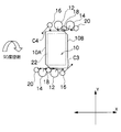
- FIG. 1A and 1B are plan views of the glass substrate chamfering apparatus according to the embodiment. Further, in FIG. 1A, for example, a corner cutting grindstone 16, a rough chamfering first grindstone 12, and a finish chamfering chamfer facing the long sides 10 ⁇ / b> A and 10 ⁇ / b> B of the liquid crystal display glass substrate 10 of 2000 ⁇ 1800 mm.
- the first grindstone 18, the second grindstone 14 for rough chamfering, and the second grindstone 20 for finishing chamfering are substantially parallel to the long sides 10A and 10B of the glass substrate 10 and the traveling direction of the grindstone ( A plan view arranged in a predetermined position in the order described above from the front in the X direction) is shown.
- FIG. 1A for example, a corner cutting grindstone 16, a rough chamfering first grindstone 12, and a finish chamfering chamfer facing the long sides 10 ⁇ / b> A and 10 ⁇ / b> B of the liquid crystal display glass substrate 10 of
- the glass substrate 10 for liquid crystal displays was illustrated, the glass substrate for plasma displays may be sufficient.
- the corner cutting grindstone 16 may be disposed downstream of the traveling direction in the X direction, but is disposed upstream of the traveling direction from the viewpoint of improving tact.
- the glass substrate 10 is held by suction on a chamfer table 22 indicated by a broken line in the figure.
- the grindstones 12 to 20 are each rotated at a predetermined rotational speed by a rotation driving unit (not shown), and a grindstone group arranged on the X direction (long side 10A side and 10B side) by a movement driving unit (not shown). Both move in the X direction, but each travels at a constant speed in the opposite direction. Thereby, the corner cut processing of the corners C1 and C2 of the glass substrate 10, the rough chamfering processing of the long sides 10A and 10B of the glass substrate 10, and the finishing chamfering processing are performed.
- the grindstone 12 preferably starts chamfering from approximately the center of the long sides 10A and 10B and stops chamfering when it passes through the long sides 10A and 10B. Moreover, the grindstone 14 stops the chamfering process when a little amount has passed the starting point of the grindstone 12.
- the grindstones 18 and 20 also operate in the same manner as the grindstones 12 and 14, respectively.
- a dedicated grindstone 16 is provided from the viewpoint of improving tact.
- the grindstone 12 is moved in an oblique direction with respect to the X direction so that the corners C1 and C2 of the glass substrate 10 are moved. You may cut corners.
- the rough chamfering processing of the long sides 10A and 10B, the finishing chamfering processing, and the corner cutting processing of the corners C1 and C2 are simultaneously performed by each of the grindstones 12 to 20, and then the glass substrate 10 is processed as shown in FIG. 1B. Is moved to the downstream side of the chamfering process and rotated 90 degrees, thereby simultaneously performing rough chamfering processing of the short sides 10C and 10D, finishing chamfering processing, and corner cutting processing of the remaining corners C3 and C4.
- the production line length of the glass substrate 10 can be shortened and the equipment is also inexpensive. Since it is necessary to arrange a large number of chamfering heads in a narrow space, chamfering the four sides of the glass substrate 10 at the same time is difficult in terms of equipment configuration. Further, the chamfering process may be performed for each side of the glass substrate 10, but it is desirable to perform the chamfering process on two sides simultaneously as described above from the viewpoint of improving the tact.
- FIGS. 1A and 1B a chamfering apparatus in which a plurality of grindstones 12 to 20 such as a corner cutting grindstone 16, a rough chamfering grindstone 12, 14 and a finishing chamfering grindstone 18, 20 are installed.
- a chamfering apparatus in which a plurality of grindstones 12 to 20 such as a corner cutting grindstone 16, a rough chamfering grindstone 12, 14 and a finishing chamfering grindstone 18, 20 are installed.
- the present invention is not limited to this.
- one side of the glass substrate 10 can be chamfered with one rough chamfering grindstone and one finish chamfering grindstone. That is, it can be applied to collective chamfering instead of divided chamfering. However, it is desirable to perform chamfering as described above from the viewpoint of improving tact.
- the present invention can also be applied to a chamfering apparatus in which only the grindstone 16 for corner cutting, only the grindstones 12 and 14 for rough chamfering, or only the grindstones 18 and 20 for finishing chamfering are installed.
- the groove shape of a plurality of chamfering grindstones 12, 14, 16, 18, and 20 can be detected by one laser displacement meter 30 (see FIG. 2: groove shape detecting means) described later, FIG.
- the present invention is effective for the chamfering apparatus used in combination with a plurality of units shown in 1B.
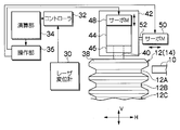
- FIG. 2 is a system configuration diagram in which the configuration of the chamfering device of the embodiment is added to the grindstone 12 (14) for rough chamfering.
- This system is composed of a laser displacement meter 30, a controller 32, a calculation unit (control unit) 34, and an operation unit 36.
- the system is also commonly used for the grindstone 16 for corner cutting and the grindstones 18 and 20 for finishing chamfering.
- This chamfering apparatus shown in FIGS. 1A and 1B one system is installed for the grindstone group on the long side 10B side, and one unit is installed for the grindstone group on the long side 10A side.
- the features of the present system will be described using the grindstone 12 (14) as an example, but the same applies to the grindstones 16, 18, and 20.
- the grindstone 12 is a cylindrical grindstone in which a plurality of annular grooves 12A, 12B, 12C,...
- Each of the grooves 12 ⁇ / b> A, 12 ⁇ / b> B, 12 ⁇ / b> C... Has the same shape, and is formed in a tapered shape that becomes wider toward the outer periphery of the grindstone 12.
- the tapered surfaces of the grooves 12A, 12B, 12C,... Form a predetermined angle with respect to the inner bottom surface of the grooves.
- abrasive grains such as diamond abrasive grains are sintered on the inner surfaces of the grooves 12A, 12B, 12C.
- a flat flange 38 is fixed to the upper portion of the grindstone 12 by a bolt (not shown), and a shaft 40 along the central axis of the grindstone 12 projects from the upper surface of the flange 38.
- the shaft 40 is detachably held by a hydraulic chuck 46 of a spindle (rotation drive unit) 44 that is supported by the grindstone head 42 so as to be movable up and down. That is, the grindstone 12 is attached to and detached from the spindle 44 through the hydraulic chuck 46 during replacement and maintenance, and the rotational driving force of the spindle 44 is transmitted through the hydraulic chuck 46 to be rotated at a predetermined rotational speed.
- the spindle 44 is supported on the grindstone head 42 so as to be movable up and down via a guide (not shown), and a spindle (not shown) of a servo motor (first moving unit) 48 is connected to the upper part thereof.
- the power of the servo motor 48 moves the grinding wheel head 42 up and down with an accuracy of micron.
- the grindstone 12 is moved up and down in a direction perpendicular to the surface of the glass substrate 10, so that the heights of the grooves 12A, 12B, 12C.
- the grindstone head 42 is supported so as to be movable in the horizontal direction via a guide (not shown), and a spindle 52 of a servo motor (second moving unit) 50 is connected to the side of the grindstone head 42.
- the grindstone head 42 is moved horizontally with an accuracy of a micron by the power.
- the grindstone 12 is horizontally moved in the surface direction of the glass substrate 10, so that the horizontal position of the grooves 12A, 12B, 12C... Of the grindstone 12 with respect to the end surface of the glass substrate 10 is adjusted with an accuracy of micron.
- the grindstone head 42, the spindle 44, the hydraulic chuck 46, the servo motor 48, and the servo motor 50 described above are similarly provided for the grindstones 16, 18, and 20.
- the detection surface of the laser displacement meter 30 is disposed opposite to the grindstone 12 and can detect the position and shape of the plurality of grooves 12A, 12B, 12C.
- Information indicating the groove shape including the position information is output from the laser displacement meter 30 to the calculation unit 34 via the controller 32.
- the position information shown here is position information in a direction orthogonal to the surface of the glass substrate 10 held on the chamfering table 22 and position information in the surface direction of the glass substrate 10.
- the storage unit built in the calculation unit 34 stores the reference groove shape (including the position information) of the design value of the grindstone 12 at the position where the grindstone 12 is attached to the reference position of the hydraulic chuck 46 of the spindle 44. ing.
- the calculation unit 34 operates the servo motor 48 and / or the servo motor 50 based on the stored reference groove shape and the actual groove shape (including the position information) detected by the laser displacement meter 30.
- the grindstone 12 is moved in the orthogonal direction and / or the surface direction by controlling through the part 36.
- a monitor (not shown) is connected to the calculation unit 34, and the actual groove shape is superimposed on the reference groove shape and displayed on the monitor. By observing this monitor, the positional deviation of the actual groove shape with respect to the reference groove shape can be visually recognized, and the runout of the grindstone 12 can be corrected while observing this monitor.
- a new grindstone 12 is attached to the hydraulic chuck 46 of the spindle 44, and the position and shape of the grooves 12A, 12B, 12C...
- Information indicating the groove shape is output to the calculation unit 34. Since the storage unit of the calculation unit 34 stores the reference groove shape of the design value of the grindstone 12 including the position information at the position attached to the reference position of the hydraulic chuck 46 of the spindle 44 as described above, the calculation unit 34 34 controls the servo motor 48 and / or the servo motor 50 based on the reference groove shape and the actual groove shape detected by the laser displacement meter 30 to move the grindstone 12 in the vertical direction and / or the horizontal direction. To set the condition of the grindstone 12.
- the chamfering apparatus of the embodiment since the laser displacement meter 30 that directly detects the groove shape of the grindstone 12 is provided, the height of the grindstone 12 can be corrected with high accuracy. Can be corrected, and the life of the grindstone 12 can be detected. Details of this will be described later. Therefore, according to the chamfering apparatus of the embodiment, the end surface of the glass substrate 10 can be chamfered with high quality.
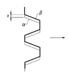
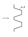
- the calculation unit 34 determines the actual groove shape and groove position detected by the laser displacement meter 30 at the time of exchanging the grindstone, that is, the actual groove shapes ⁇ and ⁇ indicated by the thin lines in FIG. The positions of the reference groove shapes ⁇ and ⁇ indicated by the 3A thick line are compared. When the actual groove shapes ⁇ and ⁇ do not coincide with the positions of the reference groove shapes ⁇ and ⁇ in the vertical direction, the calculation unit 34 calculates the shift amount a. And the calculating part 34 controls the servomotor 48 by the deviation
- the actual groove shapes ⁇ and ⁇ coincide with the positions of the reference groove shapes ⁇ and ⁇ in the vertical direction. Therefore, according to the chamfering apparatus of the embodiment, the height of the grindstone 12 can be corrected automatically and with high accuracy. Since the height of the grindstone 12 is accurately corrected to a position that satisfies the product standard, it is possible to prevent the occurrence of product defects in which only a part of the end surface of the glass substrate 10 is a mirror surface. Moreover, since the end surface dimension of the glass substrate 10 falls into the product standard, the yield of the glass substrate 10 is improved.
- the calculation unit 34 uses the actual groove shape and groove position detected by the laser displacement meter 30 during chamfering processing, that is, the actual groove shape ⁇ and ⁇ indicated by the thin line in FIG. 4A and the thick line in FIG. 4A.
- the actual groove wear amount b is calculated by comparing the reference groove shapes ⁇ and ⁇ shown, and the servomotor 50 is controlled so as to cancel the wear amount b, thereby moving the grindstone 12 in the horizontal direction (see FIG. 4A, the servo motor 50 is stopped at the offset position shown in FIG. 4B.
- the chamfering apparatus of the embodiment since the grinding rate by the grindstone 12 (the polishing rate in the case of a finishing grindstone) can be automatically made constant, high-precision chamfering processing becomes possible, and glass
- the external dimensions of the substrate 10 are also substantially constant.
- the calculation section 34 stores a life groove shape ⁇ for determining the life of the groove, and the actual groove shape detected by the laser displacement meter 30 during the chamfering process, that is, FIG.
- the actual groove shape ⁇ shown by the thin line is compared with the life groove shape ⁇ shown by the thick line in FIG.
- the calculation unit 34 controls the servo motor 48 to use the next groove (for example, the groove 12B) of the grindstone 12 so that the grindstone 12 is moved upward. Move.
- the life of the grooves 12A, 12B, 12C,... Of the grindstone 12 can be automatically determined, and the groove 12A that has run out of life is automatically set to the next groove 12B. be able to.
- the confirmation of the groove shape and the groove position by the laser displacement meter 30 is, of course, performed at the time of exchanging the grindstone 12, but it may be performed every time the chamfering of one glass substrate 10 is completed. It may be performed every time the processing of the sheet is completed. The latter is preferable in view of productivity.
- Example ⁇ Using a laser displacement meter, let the computing unit recognize the normal height of the grinding wheel that is within the standard width of the end face of the glass substrate, and intentionally insert a specified thin plate (shim) into the chamfering device. It was confirmed that a height difference between the height and the actual whetstone height was generated, and that the whetstone could be guided to a whetstone height within the surface width standard after the height difference was automatically corrected.
- shim thin plate
Landscapes
- Engineering & Computer Science (AREA)
- Mechanical Engineering (AREA)
- Chemical & Material Sciences (AREA)
- Ceramic Engineering (AREA)
- Inorganic Chemistry (AREA)
- Grinding And Polishing Of Tertiary Curved Surfaces And Surfaces With Complex Shapes (AREA)
- Constituent Portions Of Griding Lathes, Driving, Sensing And Control (AREA)
Abstract
Description
そして、演算部34は、実際の溝形状αが寿命溝形状γに一致すると、砥石12の次の溝(例えば溝12B)を使用するようにサーボモータ48を制御して、砥石12を上方に移動させる。これにより、実施の形態の面取装置によれば、砥石12の溝12A、12B、12C…の寿命を自動で判定でき、かつ、寿命が尽きた溝12Aから次の溝12Bに自動で設定することができる。
レーザー変位計を使用し、ガラス基板の端面の面幅規格内となる砥石正規高さを演算部に認識させ、意図的に規定値の薄板(シム)を面取装置に挿入し、前記砥石正規高さと実際の砥石高さとの高低差を発生させ、前記高低差の自動補正後、砥石を面幅規格内となる砥石高さに誘導できることを確認した。
砥石交換後、ガラス基板の端面を面取り加工し、測定台にて面幅確認を実施したところ規格外となり、砥石の高さ方向の補正量を再入力して再度面取り加工を実施し、条件出しを行うことになった。その結果、複数枚のガラス基板のロスが発生した場合もあった。
本出願は、2009年4月3日出願の日本特許出願(特願2009-091402)に基づくものであり、その内容はここに参照として取り込まれる。
12…粗面取り用の第1の砥石
14…粗面取り用の第2の砥石
16…コーナーカット用の砥石
18…仕上げ面取り用の第1の砥石
20…仕上げ面取り用の第2の砥石
22…面取りテーブル
30…レーザー変位計
32…コントローラ
34…演算部
36…操作部
38…フランジ
40…軸
42…砥石ヘッド
44…スピンドル
46…油圧チャック
48…サーボモータ
50…サーボモータ
52…スピンドル
Claims (5)
- ガラス基板を保持するテーブルと、
前記テーブルに保持されたガラス基板の端面を面取り加工するための環状の溝がその軸方向に所定の間隔をもって複数本形成された円柱状の砥石と、
前記砥石を回転させる回転駆動部と、
前記砥石を前記テーブルに保持されたガラス基板の面に対して直交する方向に移動させる第1の移動部と、
前記砥石を前記テーブルに保持されたガラス基板の面方向に移動させる第2の移動部と、
前記砥石の複数本の環状溝の前記直交方向及び前記面方向の位置情報も含む溝形状を検出する溝形状検出手段と、
前記砥石が前記回転駆動部の基準の位置に取り付けられた位置における前記直交方向及び前記面方向の位置情報も含む砥石の設計値の基準溝形状が記憶され、該基準溝形状と前記溝形状検出手段によって検出された前記溝形状に基づいて前記第1の移動部及び/又は前記第2の移動部を制御する制御部と、
を備えたことを特徴とするガラス基板の面取装置。 - 前記制御部は、前記砥石を交換時に前記溝形状検出手段によって検出された前記溝形状と前記記憶された基準溝形状とを比較して、該基準溝形状に前記溝形状が合致していない場合には、該基準溝形状に前記溝形状が合致するように前記第1の移動部を制御して前記砥石を移動させ、合致した位置で第1の移動部を停止させる請求項1に記載のガラス基板の面取装置。
- 前記制御部は、前記面取り加工時に前記溝形状検出手段によって検出された前記溝形状と前記記憶された基準溝形状とを比較して、当該溝の磨耗量を演算し、該磨耗量を相殺するように前記第2の移動部を制御して前記砥石を移動させ、相殺した位置で第2の移動部を停止させる請求項1又は2に記載のガラス基板の面取装置。
- 前記制御部には、前記溝の寿命を判定するための寿命溝形状が記憶され、前記面取り加工時に前記溝形状検出手段によって検出された前記溝形状と前記記憶された寿命溝形状とを比較して、前記溝形状が前記寿命溝形状となると、前記砥石の次の溝を使用するように前記第1の移動部を制御する請求項1乃至3のいずれかに記載のガラス基板の面取装置。
- 前記砥石は、粗面取り用砥石及び/又は仕上げ面取り用砥石である請求項1乃至4のいずれかに記載のガラス基板の面取装置。
Priority Applications (3)
| Application Number | Priority Date | Filing Date | Title |
|---|---|---|---|
| JP2011507238A JPWO2010113982A1 (ja) | 2009-04-03 | 2010-03-30 | ガラス基板の面取装置 |
| KR1020117017789A KR20120013929A (ko) | 2009-04-03 | 2010-03-30 | 유리 기판의 모따기 장치 |
| CN2010800061058A CN102300673A (zh) | 2009-04-03 | 2010-03-30 | 玻璃基板的倒棱装置 |
Applications Claiming Priority (2)
| Application Number | Priority Date | Filing Date | Title |
|---|---|---|---|
| JP2009-091402 | 2009-04-03 | ||
| JP2009091402 | 2009-04-03 |
Publications (1)
| Publication Number | Publication Date |
|---|---|
| WO2010113982A1 true WO2010113982A1 (ja) | 2010-10-07 |
Family
ID=42828271
Family Applications (1)
| Application Number | Title | Priority Date | Filing Date |
|---|---|---|---|
| PCT/JP2010/055768 Ceased WO2010113982A1 (ja) | 2009-04-03 | 2010-03-30 | ガラス基板の面取装置 |
Country Status (5)
| Country | Link |
|---|---|
| JP (1) | JPWO2010113982A1 (ja) |
| KR (1) | KR20120013929A (ja) |
| CN (1) | CN102300673A (ja) |
| TW (1) | TW201105461A (ja) |
| WO (1) | WO2010113982A1 (ja) |
Cited By (3)
| Publication number | Priority date | Publication date | Assignee | Title |
|---|---|---|---|---|
| CN109590893A (zh) * | 2019-01-04 | 2019-04-09 | 京东方科技集团股份有限公司 | 利用研磨系统的研磨方法、研磨系统 |
| CN110653719A (zh) * | 2019-10-08 | 2020-01-07 | 彩虹(合肥)液晶玻璃有限公司 | 研磨装置及研磨加工线 |
| KR20250119469A (ko) | 2024-01-31 | 2025-08-07 | 에이지씨 가부시키가이샤 | 연마 장치 및 연마 방법 |
Families Citing this family (12)
| Publication number | Priority date | Publication date | Assignee | Title |
|---|---|---|---|---|
| KR101378279B1 (ko) * | 2012-08-17 | 2014-04-01 | 하이디스 테크놀로지 주식회사 | 디스플레이 패널용 연마장치 및 연마방법 |
| CN103624656A (zh) * | 2012-08-22 | 2014-03-12 | 许春雷 | 一种路缘石组合式多面打磨机 |
| CN103962909A (zh) * | 2013-01-24 | 2014-08-06 | 上海京美电脑机械有限公司 | 玻璃加工方法及其使用于该玻璃加工方法的研磨轮 |
| CN106183581B (zh) * | 2016-08-23 | 2018-09-18 | 伯恩高新科技(惠州)有限公司 | 一种同时精雕加工叠加玻璃的方法及其装置 |
| CN109420962A (zh) * | 2017-08-25 | 2019-03-05 | 蓝思科技(长沙)有限公司 | 一种电子抛光装置及方法 |
| CN109249306B (zh) * | 2018-09-30 | 2021-04-13 | 广东长盈精密技术有限公司 | 抛光设备 |
| CN109304667A (zh) * | 2018-10-26 | 2019-02-05 | 东旭科技集团有限公司 | 研磨装置 |
| KR102775841B1 (ko) * | 2019-04-11 | 2025-03-05 | (주)이티에스 | 글래스 가공장치용 연마부재 및 그 제조방법 |
| CN111761420B (zh) * | 2020-06-16 | 2021-10-15 | 上海中欣晶圆半导体科技有限公司 | 一种提高硅片倒角宽幅精度的方法 |
| JP7630127B2 (ja) * | 2021-03-18 | 2025-02-17 | 坂東機工株式会社 | 脆性板の加工装置および脆性板の加工方法 |
| CN112975645A (zh) * | 2021-03-24 | 2021-06-18 | 深圳市久久犇自动化设备股份有限公司 | 用于玻璃磨边机的磨边模组 |
| CN118024129A (zh) * | 2024-03-18 | 2024-05-14 | 彩虹(合肥)液晶玻璃有限公司 | 一种研磨轮自动校准装置 |
Citations (6)
| Publication number | Priority date | Publication date | Assignee | Title |
|---|---|---|---|---|
| JPH11300612A (ja) * | 1998-04-22 | 1999-11-02 | Asahi Glass Co Ltd | 板状体の研削方法及び装置 |
| JP2000190233A (ja) * | 1998-12-28 | 2000-07-11 | Uchiyama Konpo Shizai Shiki:Kk | 研削用回転砥石 |
| JP2002205264A (ja) * | 2000-12-28 | 2002-07-23 | Sodeyama Giken Kogyo Kk | 板材端面研削方法および装置 |
| JP2004025358A (ja) * | 2002-06-25 | 2004-01-29 | Nakamura Tome Precision Ind Co Ltd | ガラス基板の研削装置 |
| JP2005319562A (ja) * | 2004-05-07 | 2005-11-17 | Akimichi Koide | ディスプレイ用ガラスの端面研削工具 |
| JP2008049449A (ja) * | 2006-08-25 | 2008-03-06 | Asahi Glass Co Ltd | 板状体の面取り方法及びその装置 |
Family Cites Families (2)
| Publication number | Priority date | Publication date | Assignee | Title |
|---|---|---|---|---|
| US6325704B1 (en) * | 1999-06-14 | 2001-12-04 | Corning Incorporated | Method for finishing edges of glass sheets |
| JP4406752B2 (ja) * | 2005-05-27 | 2010-02-03 | 日本電気硝子株式会社 | ガラス基板の端面加工装置及び端面加工方法 |
-
2010
- 2010-03-30 CN CN2010800061058A patent/CN102300673A/zh active Pending
- 2010-03-30 WO PCT/JP2010/055768 patent/WO2010113982A1/ja not_active Ceased
- 2010-03-30 KR KR1020117017789A patent/KR20120013929A/ko not_active Withdrawn
- 2010-03-30 JP JP2011507238A patent/JPWO2010113982A1/ja not_active Withdrawn
- 2010-04-02 TW TW099110430A patent/TW201105461A/zh unknown
Patent Citations (6)
| Publication number | Priority date | Publication date | Assignee | Title |
|---|---|---|---|---|
| JPH11300612A (ja) * | 1998-04-22 | 1999-11-02 | Asahi Glass Co Ltd | 板状体の研削方法及び装置 |
| JP2000190233A (ja) * | 1998-12-28 | 2000-07-11 | Uchiyama Konpo Shizai Shiki:Kk | 研削用回転砥石 |
| JP2002205264A (ja) * | 2000-12-28 | 2002-07-23 | Sodeyama Giken Kogyo Kk | 板材端面研削方法および装置 |
| JP2004025358A (ja) * | 2002-06-25 | 2004-01-29 | Nakamura Tome Precision Ind Co Ltd | ガラス基板の研削装置 |
| JP2005319562A (ja) * | 2004-05-07 | 2005-11-17 | Akimichi Koide | ディスプレイ用ガラスの端面研削工具 |
| JP2008049449A (ja) * | 2006-08-25 | 2008-03-06 | Asahi Glass Co Ltd | 板状体の面取り方法及びその装置 |
Cited By (4)
| Publication number | Priority date | Publication date | Assignee | Title |
|---|---|---|---|---|
| CN109590893A (zh) * | 2019-01-04 | 2019-04-09 | 京东方科技集团股份有限公司 | 利用研磨系统的研磨方法、研磨系统 |
| CN109590893B (zh) * | 2019-01-04 | 2021-01-26 | 京东方科技集团股份有限公司 | 利用研磨系统的研磨方法、研磨系统 |
| CN110653719A (zh) * | 2019-10-08 | 2020-01-07 | 彩虹(合肥)液晶玻璃有限公司 | 研磨装置及研磨加工线 |
| KR20250119469A (ko) | 2024-01-31 | 2025-08-07 | 에이지씨 가부시키가이샤 | 연마 장치 및 연마 방법 |
Also Published As
| Publication number | Publication date |
|---|---|
| CN102300673A (zh) | 2011-12-28 |
| TW201105461A (en) | 2011-02-16 |
| KR20120013929A (ko) | 2012-02-15 |
| JPWO2010113982A1 (ja) | 2012-10-11 |
Similar Documents
| Publication | Publication Date | Title |
|---|---|---|
| JPWO2010113982A1 (ja) | ガラス基板の面取装置 | |
| CN101088706B (zh) | 用于将工件研磨和/或抛光到光学质量的研磨和抛光机 | |
| JP5820329B2 (ja) | 両頭平面研削法及び両頭平面研削盤 | |
| TW201029797A (en) | Lens processing method and grinding device | |
| KR20060063921A (ko) | Amlcd 기판 테두리의 압력공급연마장치 | |
| KR20140118884A (ko) | 워크의 외주가공장치 | |
| WO2009119772A1 (ja) | ガラス基板の加工方法及びその装置 | |
| EP2505306B1 (en) | Eyeglass lens periphery processing apparatus | |
| JP2015188999A (ja) | 単歯割出し研削法による傘歯車の研削加工方法 | |
| CN103639900B (zh) | 一种高精异形砂轮的加工方法 | |
| KR20030084749A (ko) | 수치 제어 공작 기계에 있어서의 가공 오차 보정 방법 및이를 이용한 연삭반 | |
| JP6190654B2 (ja) | 削り代の均一化方法及び板材の周縁研削装置 | |
| CN106965076A (zh) | 板状体的研磨方法及板状体的研磨装置 | |
| KR101143290B1 (ko) | 판상체의 연마 방법 및 그 장치 | |
| CN102427913B (zh) | 玻璃端面磨削用磨具的加工位置设定方法 | |
| JP2006026845A (ja) | 面取機の工具位置の調整方法 | |
| JP5162966B2 (ja) | 研削盤 | |
| JP5679171B2 (ja) | ダイシング装置及びダイシング方法 | |
| CN206277214U (zh) | 磨削装置 | |
| JP2021158153A (ja) | ウェハの再研削方法 | |
| JP2019084624A (ja) | ガラス板の製造方法及び砥石の位置決め固定装置 | |
| JP2012240176A (ja) | 研削加工装置及び研削加工方法 | |
| JP2001277084A (ja) | 両頭研削盤 | |
| KR100573035B1 (ko) | 웨이퍼 성형장치와 이 장치를 이용한 성형 방법 | |
| JPWO2014002447A1 (ja) | 基板端縁の研削方法及び基板端縁の研削装置 |
Legal Events
| Date | Code | Title | Description |
|---|---|---|---|
| WWE | Wipo information: entry into national phase |
Ref document number: 201080006105.8 Country of ref document: CN |
|
| 121 | Ep: the epo has been informed by wipo that ep was designated in this application |
Ref document number: 10758753 Country of ref document: EP Kind code of ref document: A1 |
|
| ENP | Entry into the national phase |
Ref document number: 20117017789 Country of ref document: KR Kind code of ref document: A |
|
| WWE | Wipo information: entry into national phase |
Ref document number: 2011507238 Country of ref document: JP |
|
| NENP | Non-entry into the national phase |
Ref country code: DE |
|
| 122 | Ep: pct application non-entry in european phase |
Ref document number: 10758753 Country of ref document: EP Kind code of ref document: A1 |