WO2010113850A1 - 熱源システムおよびその制御方法 - Google Patents
熱源システムおよびその制御方法 Download PDFInfo
- Publication number
- WO2010113850A1 WO2010113850A1 PCT/JP2010/055531 JP2010055531W WO2010113850A1 WO 2010113850 A1 WO2010113850 A1 WO 2010113850A1 JP 2010055531 W JP2010055531 W JP 2010055531W WO 2010113850 A1 WO2010113850 A1 WO 2010113850A1
- Authority
- WO
- WIPO (PCT)
- Prior art keywords
- cooling
- cooling tower
- capacity
- turbo
- heat source
- Prior art date
Links
Images


Classifications
-
- F—MECHANICAL ENGINEERING; LIGHTING; HEATING; WEAPONS; BLASTING
- F25—REFRIGERATION OR COOLING; COMBINED HEATING AND REFRIGERATION SYSTEMS; HEAT PUMP SYSTEMS; MANUFACTURE OR STORAGE OF ICE; LIQUEFACTION SOLIDIFICATION OF GASES
- F25B—REFRIGERATION MACHINES, PLANTS OR SYSTEMS; COMBINED HEATING AND REFRIGERATION SYSTEMS; HEAT PUMP SYSTEMS
- F25B1/00—Compression machines, plants or systems with non-reversible cycle
- F25B1/04—Compression machines, plants or systems with non-reversible cycle with compressor of rotary type
- F25B1/053—Compression machines, plants or systems with non-reversible cycle with compressor of rotary type of turbine type
-
- F—MECHANICAL ENGINEERING; LIGHTING; HEATING; WEAPONS; BLASTING
- F25—REFRIGERATION OR COOLING; COMBINED HEATING AND REFRIGERATION SYSTEMS; HEAT PUMP SYSTEMS; MANUFACTURE OR STORAGE OF ICE; LIQUEFACTION SOLIDIFICATION OF GASES
- F25B—REFRIGERATION MACHINES, PLANTS OR SYSTEMS; COMBINED HEATING AND REFRIGERATION SYSTEMS; HEAT PUMP SYSTEMS
- F25B49/00—Arrangement or mounting of control or safety devices
- F25B49/02—Arrangement or mounting of control or safety devices for compression type machines, plants or systems
- F25B49/027—Condenser control arrangements
-
- F—MECHANICAL ENGINEERING; LIGHTING; HEATING; WEAPONS; BLASTING
- F28—HEAT EXCHANGE IN GENERAL
- F28B—STEAM OR VAPOUR CONDENSERS
- F28B9/00—Auxiliary systems, arrangements, or devices
- F28B9/04—Auxiliary systems, arrangements, or devices for feeding, collecting, and storing cooling water or other cooling liquid
- F28B9/06—Auxiliary systems, arrangements, or devices for feeding, collecting, and storing cooling water or other cooling liquid with provision for re-cooling the cooling water or other cooling liquid
-
- F—MECHANICAL ENGINEERING; LIGHTING; HEATING; WEAPONS; BLASTING
- F25—REFRIGERATION OR COOLING; COMBINED HEATING AND REFRIGERATION SYSTEMS; HEAT PUMP SYSTEMS; MANUFACTURE OR STORAGE OF ICE; LIQUEFACTION SOLIDIFICATION OF GASES
- F25B—REFRIGERATION MACHINES, PLANTS OR SYSTEMS; COMBINED HEATING AND REFRIGERATION SYSTEMS; HEAT PUMP SYSTEMS
- F25B2400/00—General features or devices for refrigeration machines, plants or systems, combined heating and refrigeration systems or heat-pump systems, i.e. not limited to a particular subgroup of F25B
- F25B2400/06—Several compression cycles arranged in parallel
-
- F—MECHANICAL ENGINEERING; LIGHTING; HEATING; WEAPONS; BLASTING
- F25—REFRIGERATION OR COOLING; COMBINED HEATING AND REFRIGERATION SYSTEMS; HEAT PUMP SYSTEMS; MANUFACTURE OR STORAGE OF ICE; LIQUEFACTION SOLIDIFICATION OF GASES
- F25B—REFRIGERATION MACHINES, PLANTS OR SYSTEMS; COMBINED HEATING AND REFRIGERATION SYSTEMS; HEAT PUMP SYSTEMS
- F25B2700/00—Sensing or detecting of parameters; Sensors therefor
- F25B2700/21—Temperatures
- F25B2700/2106—Temperatures of fresh outdoor air
-
- F—MECHANICAL ENGINEERING; LIGHTING; HEATING; WEAPONS; BLASTING
- F28—HEAT EXCHANGE IN GENERAL
- F28C—HEAT-EXCHANGE APPARATUS, NOT PROVIDED FOR IN ANOTHER SUBCLASS, IN WHICH THE HEAT-EXCHANGE MEDIA COME INTO DIRECT CONTACT WITHOUT CHEMICAL INTERACTION
- F28C1/00—Direct-contact trickle coolers, e.g. cooling towers
- F28C2001/006—Systems comprising cooling towers, e.g. for recooling a cooling medium
-
- F—MECHANICAL ENGINEERING; LIGHTING; HEATING; WEAPONS; BLASTING
- F28—HEAT EXCHANGE IN GENERAL
- F28F—DETAILS OF HEAT-EXCHANGE AND HEAT-TRANSFER APPARATUS, OF GENERAL APPLICATION
- F28F27/00—Control arrangements or safety devices specially adapted for heat-exchange or heat-transfer apparatus
Definitions
- the present invention relates to a heat source system for improving the efficiency of the entire heat source system and a control method thereof.
- a system including a plurality of turbo chillers that can be started and stopped according to the amount of heat required by an external load is known.
- the cooling water pump for supplying the cooling water to the condenser of the centrifugal chiller, and the cooling water whose temperature is recovered by collecting the condensation heat in the condenser are brought into contact with the outside air
- a cooling tower that cools the cooling water and a cooling water pump that supplies the cooling water cooled by the evaporator of the turbo refrigerator to an external load is provided with a cooling tower fan for introducing outside air into the cooling tower.
- Patent Document 1 discloses an invention for improving the operation efficiency of the entire heat source system in consideration of not only a refrigerator alone but also auxiliary equipment such as a cooling water pump, a cooling tower, and a cooling water pump.
- auxiliary equipment such as a cooling water pump, a cooling tower, and a cooling water pump.
- the heat source system described in Patent Document 1 is premised on a configuration in which each cooling tower is independently connected to each refrigerator as shown in FIG.
- a heat source system including a plurality of cooling towers commonly connected to each turbo refrigerator.
- multiple cooling towers are activated so that the cooling tower capacity is larger than the capacity corresponding to the operating centrifugal chillers.
- the cooling capacity increases and the cooling water temperature Go down.
- the power consumption of the turbo chiller decreases and the efficiency increases.
- the power consumption of the cooling tower fan increases, so that the efficiency of the heat source system as a whole may be reduced.
- the increase in the power consumption of the cooling tower fan is relatively small. Rather, the power consumption of the centrifugal chiller is reduced, and the efficiency of the entire heat source system may be increased.
- the efficiency of the entire heat source system is improved by appropriately selecting the number of cooling towers to be started. It is thought that you can.
- the present invention has been made in view of such circumstances, and provides a heat source system capable of improving the efficiency of the entire heat source system by appropriately selecting the number of cooling towers to be started and a control method thereof. With the goal.
- a heat source system includes a turbo compressor that compresses a refrigerant by changing a rotation frequency by electric drive, a condenser that condenses and liquefies the refrigerant compressed by the turbo compressor, An expansion valve that expands the refrigerant condensed and liquefied by the condenser, and a turbo refrigerator that includes an evaporator that evaporates the refrigerant expanded by the expansion valve, and the refrigerant by exchanging heat in the condenser An electrically driven cooling water pump for supplying cooling water to be cooled; a cooling tower for cooling the cooling water introduced from the condenser by the cooling water pump by bringing the cooling water into contact with outside air; and the cooling tower An electrically driven cooling tower fan that guides outside air into the cooling tower, and an electric drive that supplies cold water cooled by performing heat exchange in the evaporator to
- a plurality of towers are provided so as to have a cooling tower capacity corresponding to a total capacity of the rated capacity of each of the turbo chillers, and in a heat source system commonly connected to the plurality of turbo chillers,
- the number of operating units of the cooling tower can be switched by the control unit so that the capacity of the cooling tower can be changed, and the control unit previously has an outdoor wet bulb temperature and the turbo refrigerator partial load factor.
- the cooling water pump, the cooling tower, the cooling tower fan, and the cooling tower having high heat source system efficiency considering the cooling water pump.
- the optimum cooling tower capacity relationship indicating the relationship between the rejection tower capacity is stored, and the control unit is configured to determine the optimum cooling tower based on the outside wet bulb temperature during operation and the partial load factor of the turbo chiller.
- the operation number of the cooling tower is determined with reference to the capacity relationship.
- a cooling tower having a cooling capacity exceeding the rated capacity of one turbo chiller can be activated.
- a cooling tower having a cooling capacity exceeding the rated capacity of one turbo chiller can be activated.
- a cooling tower having a cooling capacity exceeding the rated capacity of one turbo chiller can be activated.
- such a state can be realized by operating a plurality of cooling towers. In such a state, since the cooling water temperature is lowered, a reduction in power consumption of the turbo chiller can be expected.
- many cooling tower fans are activated, and power consumption by the cooling tower fans can be increased.
- the present inventor has found that there is a cooling tower capacity (for example, the number of cooling towers to be activated) in which the heat source system efficiency is increased by the outside wet bulb temperature and the turbo refrigerator partial load factor. Therefore, in advance, a cooling tower capacity with high heat source system efficiency is obtained in the relationship between the outside air wet bulb temperature and the turbo refrigerator partial load factor, and the operation is performed based on this. Thereby, a highly efficient operation can be realized as the entire heat source system.
- a cooling tower capacity for example, the number of cooling towers to be activated
- the number of cooling towers to be operated can be determined simply by obtaining the outside air wet bulb temperature and the turbo refrigerator partial load factor, extremely simple operation control is possible.
- the outside air wet bulb temperature for example, it is preferable to use a humidity sensor.
- the outdoor wet bulb temperature may be output with the dry bulb temperature, relative humidity, and external pressure.
- control unit is configured to operate the turbo chiller in operation when the outside air wet bulb temperature is equal to or lower than the first predetermined temperature based on the optimum cooling tower capacity relationship. It is good also as a structure which determines the operating number of the said cooling tower so that it may become 1st capacity
- the first predetermined temperature is set as the upper limit value of this state, it is irrelevant to the partial load factor of the centrifugal chiller.
- the number of cooling towers to be operated can be determined only by the outside air wet bulb temperature, simple operation control is realized.
- the control unit when the outdoor wet bulb temperature is equal to or higher than a second predetermined temperature and the turbo refrigerator partial load factor is equal to or lower than the predetermined load factor, It is good also as a structure which determines the operation number of the said cooling tower so that it may become the equivalent capacity
- the number of cooling towers to be operated is set to be equal to the rated capacity of the operating centrifugal chiller.
- the efficiency of the heat source system as a whole was found to be high. Accordingly, when the heat source system is operated when the temperature of the outside wet bulb is relatively high and the required heat amount of the external load is small as in the intermediate period, high-efficiency operation is realized.
- the “second predetermined temperature” having the above-described configuration is set to the same value as the “first predetermined temperature” used as a threshold when determining the number of cooling towers to be operated to have the first capacity, Since it is only necessary to change the number of cooling towers using the temperature as a threshold value, more simple operation control is realized.
- the control unit has the first capacity when the outdoor wet bulb temperature is equal to or higher than the second predetermined temperature and the partial load factor of the centrifugal chiller is equal to or higher than the predetermined load factor. It is good also as a structure which determines the operating number of the said cooling tower so that it may become the 2nd capacity
- the cooling tower is configured to be equal to or lower than the first capacity and equal to or higher than the equivalent capacity. It was found that the efficiency of the heat source system as a whole increases when the number of operating units is determined. Therefore, when the heat source system is operated when the outdoor wet bulb temperature is relatively high and the required heat amount of the external load is large as in summer, a highly efficient operation is realized. In addition, when the outdoor wet bulb temperature is equal to or higher than the second predetermined temperature, it is only necessary to select the second capacity or the equivalent capacity of the above configuration using the predetermined load factor as a threshold value.
- control unit controls the flow rate of the cooling water pump based on the partial load factor of the centrifugal chiller regardless of the outdoor wet bulb temperature and the number of operating cooling towers. It is good also as a structure.
- the cooling water pump is expected to improve the efficiency by reducing the power consumption when the flow rate is reduced.
- the power consumption of the turbo chiller increases because the temperature of the cooling water rises.
- the inventor examined the cooling water flow rate for the efficiency of the heat source system as a whole, and found that it did not depend so much on the outside wet bulb temperature and the number of operating cooling towers, but greatly depended on the partial load factor of the centrifugal chiller. . Therefore, the flow rate of the cooling water pump is controlled based on the partial load factor of the centrifugal chiller regardless of the outside wet bulb temperature and the number of operating cooling towers. Thereby, simpler operation control is realized.
- the heat source system can be operated with higher efficiency by combining the above-mentioned configurations in which the number of operating cooling towers is optimally set from the viewpoint of efficiency.
- the control method of the heat source system includes a turbo compressor that compresses a refrigerant by changing a rotation frequency by electric drive, and a condenser that condenses and liquefies the refrigerant compressed by the turbo compressor.
- An electrically driven cooling water pump for supplying cooling water for cooling the refrigerant, a cooling tower for cooling the cooling water introduced from the condenser by the cooling water pump by bringing it into contact with outside air, and cooling the cooling water;
- a cooling tower fan provided in the cooling tower and electrically driven to guide the outside air into the cooling tower and an electric power for supplying cold water cooled by performing heat exchange in the evaporator to the external load side
- a chilled water pump, and a turbo chiller, the cooling water pump, the cooling tower, the cooling tower fan, and a control unit for controlling the chilled water pump, a plurality of turbo chillers are provided, A plurality of cooling towers are provided so as to have a cooling tower capacity corresponding to the total capacity of the rated capacity of each of the turbo chillers, and a heat source system commonly connected to
- the number of operating units of the cooling tower can be switched by the control unit so that the capacity of the cooling tower can be changed.
- the heat source system efficiency is high considering the turbo chiller, the cooling water pump, the cooling tower, the cooling tower fan, and the cooling water pump in relation to the machine partial load factor
- the optimum cooling tower capacity relationship indicating the relationship of the cooling tower capacity of the cooling tower is stored, and the control unit is based on the outside wet bulb temperature during operation and the partial load factor of the turbo chiller,
- the number of operating cooling towers is determined with reference to the optimum cooling tower capacity relationship.
- a cooling tower having a cooling capacity exceeding the rated capacity of one turbo chiller can be activated.
- a cooling tower having a cooling capacity exceeding the rated capacity of one turbo chiller can be activated.
- a cooling tower having a cooling capacity exceeding the rated capacity of one turbo chiller can be activated.
- such a state can be realized by operating a plurality of cooling towers. In such a state, since the cooling water temperature is lowered, a reduction in power consumption of the turbo chiller can be expected.
- many cooling tower fans are activated, and power consumption by the cooling tower fans can be increased.
- the present inventor has found that there is a cooling tower capacity (for example, the number of cooling towers to be activated) in which the heat source system efficiency is increased by the outside wet bulb temperature and the turbo refrigerator partial load factor. Therefore, in advance, a cooling tower capacity with high heat source system efficiency is obtained in the relationship between the outside air wet bulb temperature and the turbo refrigerator partial load factor, and the operation is performed based on this. Thereby, a highly efficient operation can be realized as the entire heat source system.
- a cooling tower capacity for example, the number of cooling towers to be activated
- the number of cooling towers to be operated can be determined simply by obtaining the outside air wet bulb temperature and the turbo refrigerator partial load factor, extremely simple operation control is possible.
- the outside air wet bulb temperature for example, it is preferable to use a humidity sensor.
- the outdoor wet bulb temperature may be output with the dry bulb temperature, relative humidity, and external pressure.
- the heat source system and the control method thereof according to the present invention have the following effects.
- the number of cooling towers to be operated is determined based on the relationship between the temperature of the outside wet bulb and the partial load factor of the centrifugal chiller, which indicates the cooling tower capacity of the cooling tower that is highly efficient as a whole heat source system. Therefore, highly efficient operation of the heat source system is realized by extremely simple operation control. Further, by reducing the cooling water flow rate, the operation of the heat source system with higher efficiency is realized.
- FIG. 1 is a schematic configuration diagram showing a heat source system according to an embodiment of the present invention. It is the conceptual diagram of the map which showed the optimal cooling tower capacity
- FIG. 1 shows an embodiment of the heat source system of the present invention.
- the heat source system 1 includes a turbo chiller 3 in which a plurality of units (six units in the present embodiment) are provided in parallel, and a cooling tower 5 in which a plurality of units (six units in the present embodiment) are provided in parallel.
- the turbo refrigerator 3 includes a turbo compressor 7 that compresses the refrigerant, a condenser 9 that condenses and liquefies the refrigerant compressed by the turbo compressor 7, and an expansion valve that expands the refrigerant condensed and liquefied by the condenser 9. (Not shown) and an evaporator 11 for evaporating the refrigerant expanded by the expansion valve.
- the turbo compressor 7 is driven by an electric motor 13 whose rotation frequency is variable by an inverter device.
- Cooling water supplied by a cooling water pump 15 is guided to the condenser 9.
- two cooling water pumps 15 are used in parallel, and each is driven by an electric motor (not shown) whose rotation frequency is variable by an inverter device, and only one of them is operated.
- a cooling water pump switching valve (not shown) that opens and closes is provided.
- One of the cooling water pumps 15 may be a fixed speed, and only the other may be a variable speed driven by an inverter.
- Each cooling water pump 15 sucks the cooling water guided from the cooling water return header 17 and discharges it to the condenser 9 side.
- the cooling water discharged from the condenser 9 side is guided to the cooling water header 19.
- All the turbo refrigerators 3 and all the cooling towers 5 are connected to the cooling water return header 17 in common.
- All of the centrifugal chillers 3 and all of the cooling towers 5 are connected to the cooling water header 19 in common.
- Cold water supplied by a cold water pump 21 is guided to the evaporator 11.
- two chilled water pumps 21 are used in parallel, and each is driven by an electric motor (not shown) whose rotation frequency is variable by an inverter device, and is opened and closed when only one of them is operated.
- a cold water pump switching valve (not shown) is provided.
- One of the chilled water pumps 21 may be a fixed speed, and only the other may be a variable speed driven by an inverter.
- Each chilled water pump 21 sucks chilled water guided from the chilled water return header 23 and discharges it to the evaporator 11 side.
- the cold water discharged from the evaporator 11 side is guided to the cold water header 25. All the centrifugal chillers 3 are connected to the cold water return header 23 in common.
- All the centrifugal chillers 3 are also connected to the cold water header 25 in common.
- the cold water return header 23 and the cold water return header 25 are connected to an external load (not shown).
- Cold water (for example, 7 ° C.) cooled by the evaporator 11 is supplied to the external load via the cold water forward header 25, and the cold water (for example, 12 ° C.) that has been used and heated at the external load is supplied to the cold water return header 23. Is returned to the evaporator 11 side.
- the cooling tower 5 includes a cooling tower fan 30, a sprinkling header 32, and a cooling water storage tank 34.
- the cooling tower fan 30 is used to introduce outside air into the cooling tower 5 and is driven by an electric motor 36.
- an electric motor 36 an inverter motor whose rotation frequency is variable is suitably used.
- the sprinkling header 32 scatters cooling water from above, flows down along a filler (not shown) having a large surface area provided at the bottom of the sprinkling header 32, and makes contact with outside air only by sensible heat. Cool the cooling water using the latent heat of vaporization. Between the sprinkling header 32 and the cooling water flow header 19, a cooling water flow opening / closing valve 38 is provided.
- Cooled water storage tank 34 stores cooled cooling water that has been sprayed and cooled by outside air.
- the cooling water stored in the cooling water storage tank 34 is guided to the cooling water return header 17 via the cooling water return opening / closing valve 40.
- the cooling tower 5 is started and stopped by opening and closing the cooling water return opening and closing valve 38 and the cooling water return opening and closing valve 40. Thereby, the starting number of the cooling towers 5 can be changed.
- the cooling tower 5 is provided with a humidity sensor (not shown). With this humidity sensor, the outside wet bulb temperature is obtained.
- the output of the humidity sensor is sent to a control unit described later.
- the outdoor air wet bulb temperature may be output with the dry bulb temperature, relative humidity, and external pressure.
- the heat source system includes a control unit (not shown).
- the control unit includes a turbo chiller 3, a cooling water pump 15, a cooling tower fan 30, a cooling water going on / off valve 38, a cooling water returning on / off valve 40, and The operations of the cold water pump 21, the cold water pump switching valve (not shown), and the cooling water pump switching valve (not shown) are controlled.
- the total rated capacity of all the centrifugal chillers 3 and the total rated capacity of all the cooling towers 5 are equivalent.
- the rated capacity of three of the six centrifugal chillers is 370 Rt and the rated capacity of the remaining three is 750 Rt
- the rated capacity of three of the six cooling towers is 370 Rt.
- the rated capacity of the remaining three units is 750 Rt.
- it is sufficient that the total rated capacities are equal to each other, and it is not always necessary that the respective cooling towers have the same rated capacity with respect to the rated capacities of the respective centrifugal chillers.
- the control unit has a map or a relational expression as shown in FIGS. 2 and 3 in its storage area.
- the horizontal axis indicates the partial load factor of the turbo refrigerator
- the vertical axis indicates the system COP in which the efficiency of the entire heat source system is shown.
- This map (optimum cooling tower capacity relationship) shows the cooling tower capacity of the cooling tower 5 having the highest efficiency as a whole heat source system in relation to the turbo refrigerator partial load factor and the outside air wet bulb temperature.
- a curve L1 in the figure shows an outdoor wet bulb temperature (first temperature) serving as a threshold value.
- the cooling tower capacity has the highest efficiency of 300% (upper region in the figure).
- the cooling tower capacity of 300% means a cooling tower capacity that is a total capacity of three times (300%) of the total rated capacity of the activated centrifugal chiller 3.
- a line L2 in the figure indicates a turbo chiller partial load factor (predetermined load factor) serving as a threshold value.
- predetermined load factor a turbo chiller partial load factor serving as a threshold value.
- the cooling tower capacity is most efficient when the capacity is 100% (lower left region in the figure).
- the cooling tower capacity is highest at 200% (lower right region in the figure).
- isotherms La, Lb, Lc, and Ld of the outside air wet bulb temperature are shown.
- the outdoor wet bulb temperature increases in the order of La, Lb, L1, Lc, and Ld.
- FIG. 3 shows the relationship between the flow rate of the cooling water pump 15 and the turbo refrigerator partial load factor. 100% of the cooling water pump flow rate indicates the rated flow rate.
- the control unit controls the cooling water pump flow rate based only on the partial load factor of the centrifugal chiller, regardless of the outdoor wet bulb temperature and the number of operating cooling towers 5. Also, as shown in the figure, if the cooling water pump flow rate and the turbo chiller partial load factor are expressed as a linear expression of a linear relationship, extremely simple control can be realized.
- step S1 a load and an outside air condition are obtained. Specifically, the control unit obtains the cold water inlet temperature of the cold water flowing into the evaporator 11 and the cold water outlet temperature of the cold water flowing out of the evaporator 11 by the temperature sensor. And the cold water flow volume supplied with the cold water pump 21 is obtained from a flowmeter. The control unit calculates the load consumed by the external load by multiplying the cold water inlet / outlet temperature difference obtained from the temperature sensor, the cold water flow rate, the specific heat of the cold water, and the specific gravity of the cold water. Further, the control unit obtains the outside air wet bulb temperature from a humidity sensor provided in the cooling tower 5.
- step S2 the number of operating turbo chillers 3 is determined so that the chilled water inlet temperature is equal to or lower than a predetermined value, or the conventional operation method (1), or the chilled water inlet temperature is equal to or lower than a predetermined value. It is determined (2) so that it can be maintained and the COP of the turbo chiller alone is the highest operation (the maximum COP operation here is an operation method described in JP2009-204262A). Means driving to determine the number of units in operation).
- the number of activated turbo chillers 3 is determined as a single turbo chiller regardless of the number of activated cooling towers 5.
- step S3 the flow rate of the cold water pump 21 is controlled.
- the cold water flow rate of the cold water pump 21 is determined according to the cold water demand of the external load.
- the power consumption of the chilled water pump 21 is suppressed as much as possible by reducing the flow rate of the chilled water pump 21 as much as possible to satisfy the chilled water demand as in step S4.
- the reduced flow rate of the chilled water is performed by reducing the rotational frequency of the electric motor that drives the chilled water pump 21 by the inverter device.
- the importance of the external cold water may be the pressure difference between the cold water return header 23 and the cold water return header 23 that can supply the required demand in the case of the cold water amount demand.
- step S5 the flow rate of the cooling water pump 15 is controlled.
- the flow rate of the cooling water pump 15 is obtained from the relational expression obtained in advance in step S6 as shown in FIG.
- This relational expression is described as a linear function for the turbo refrigerator partial load factor, and is stored in the storage area of the control unit. Specifically, when the rated cooling water inlet / outlet temperature difference is 5 ° C., the cooling water flow rate is 100% when the turbo refrigerator partial load factor is 100% (rated), and the turbo refrigerator partial load factor is the lowest 20 Control is performed so that the cooling water flow rate decreases monotonically as the turbo chiller partial load factor decreases so that the cooling water flow rate becomes 50%. In this way, the flow rate of the cooling water pump 15 is controlled independently from the control of the number of cooling towers.
- step S7 the number of cooling towers 5 to be started is determined.
- the required capacity QCTd for the cooling tower 5 is set to 300% (step S8).
- the outside wet bulb temperature is 10 ° C.
- the required capacity QCTd for the cooling tower 5 is set to 200% (step S8). In this case, a lower right region below the curve L1 of the map shown in FIG. 2 and to the right of the line L2 is required.
- the required capacity QCTd for the cooling tower 5 is set to 100% (step S8). In this case, a lower left region below the curve L1 of the map shown in FIG. 2 and to the left of the line L2 is required.
- step S9 the total request
- the process proceeds to step S10.
- the required capacity of the cooling tower requested in step S8 is adopted.
- the process proceeds to step S11, and the total required capacity ⁇ QCTd is corrected to be equal to the installed cooling tower total capacity ⁇ QCTi.
- the cooling tower capacity QCTd ′ that can be requested by one of the turbo chillers 3 in operation is a value obtained by dividing the installed cooling tower total capacity ⁇ QCTi by the number N of operating turbo chillers 3 (step). S12).
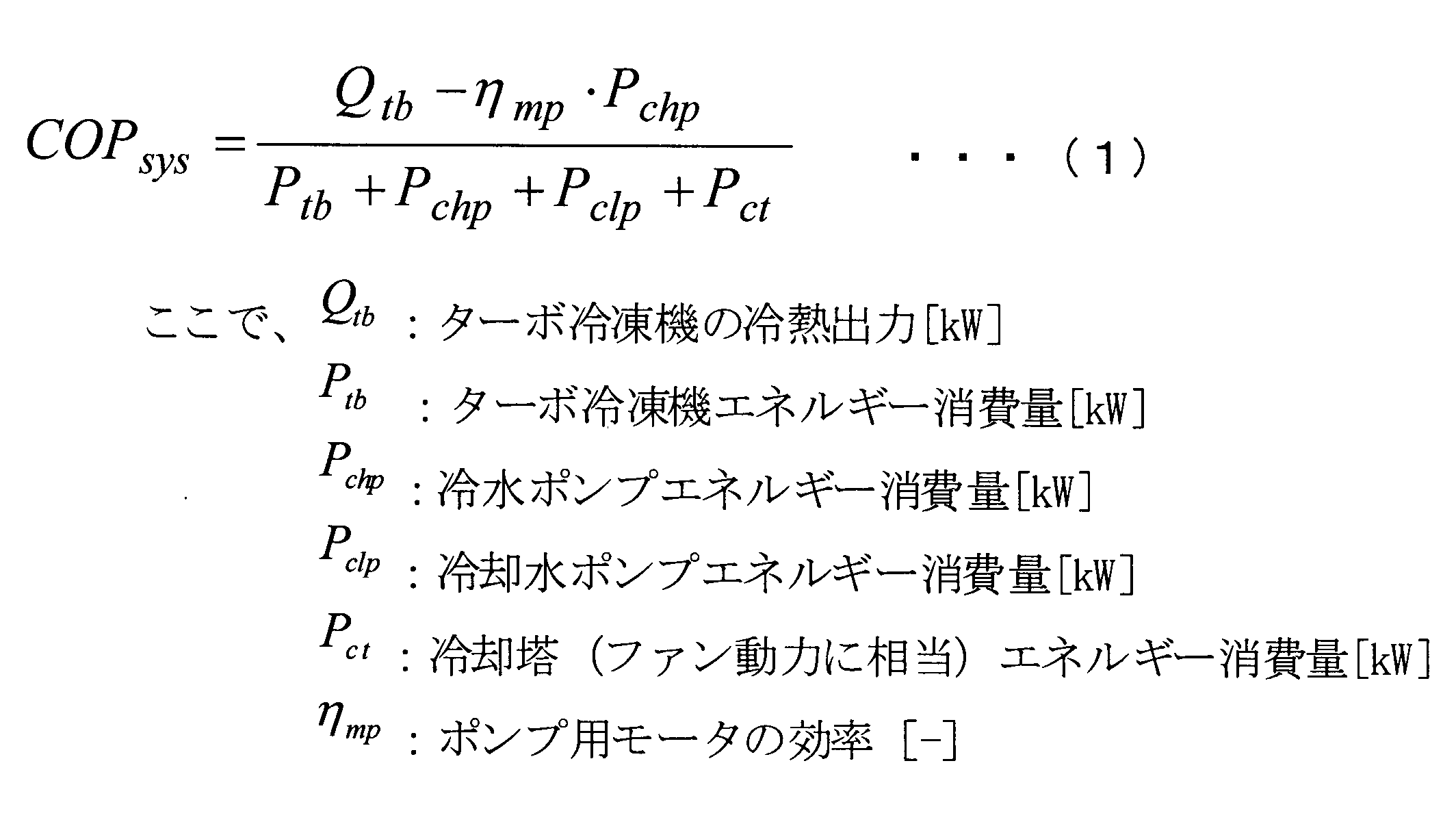
- the heat source system COP indicating the efficiency of the entire heat source system 1 is obtained by subtracting the heat input by subtracting the heat input of the chilled water pump from the amount of heat output by the turbo chiller as shown in the equation (1). , Divided by the sum of the energy consumption of the cooling tower fan.
- the energy consumption amount Ptb is calculated by dividing the thermal output Qtb of the centrifugal chiller by the COPtb obtained from the cooling water temperature, the turbo chiller partial load factor and the performance characteristics.
- Cooling Tower Fan Energy Consumption Cooling Tower Fan Power Consumption Pct [kW] is expressed as Equation (4).
- the power consumption of the cooling tower fan whose rotational speed is controlled is proportional to the cube of the air flow rate, and the air flow rate is proportional to the square of the fan rotational speed. Since a general open type cooling tower has a fan at the top of the tower, the amount of cooling water that is evaporated and released to the atmosphere is taken into consideration.
- formula (4) in order to simplify the calculation, a method is adopted in which the specific volume of air is set as the suction condition of the cooling tower and the amount of water to be evaporated is added.
- the rated conditions are a dry bulb temperature of 35 ° C. and a wet bulb temperature of 27 ° C., and the amount of water evaporation is taken into account from the amount of exhaust heat.
- FIG. 5 shows a simulation result of the refrigerator COP that shows the efficiency of the turbo refrigerator alone under the above-described conditions.
- the horizontal axis represents the turbo refrigerator partial load factor. Plotted for each outdoor wet bulb temperature.
- a solid line indicates a cooling tower capacity of 100%, and a broken line indicates a cooling tower capacity of 300%.
- the refrigerator COP is increased by increasing the cooling tower capacity from 100% to 300% for all wet bulb temperatures.
- the improvement range of the refrigerator COP is small in the low load factor region of about 20 to 40%.
- FIG. 6 shows a simulation result for the system COP showing the efficiency of the heat source system 1 under the same conditions as those in FIG.
- the solid line indicates the cooling tower capacity of 100%
- the broken line indicates the cooling tower capacity of 300%.
- the system COP is increased by increasing the cooling tower capacity from 100% to 300% at all turbo refrigerator partial load factors when the outside wet bulb temperature is 8 ° C. or less.
- the cooling tower capacity of 300% indicates a higher COP in the region where the turbo refrigerator partial load factor is large, but the region where the turbo refrigerator partial load factor is low.
- the relationship is reversed, and the cooling tower capacity of 100% indicates a higher COP.
- the turbo chiller partial load factor at which the relationship between the system COP at the cooling tower capacity of 300% and the system COP at the cooling tower capacity of 100% is reversed moves to the higher load side as the outdoor wet bulb temperature increases.
- the COP at the cooling tower capacity of 200% is good in the region where the refrigerator load factor exceeds 60%, and the COP at the cooling tower capacity of 100% becomes the highest when the temperature is 60% or less. . Therefore, when the outdoor wet bulb temperature is low in the winter or intermediate period, an energy saving effect can be obtained by increasing the cooling tower capacity to 300% regardless of the turbo refrigerator partial load factor. However, in the region where the outdoor wet bulb temperature is high and the turbo refrigerator partial load factor is low, the effect of increasing the cooling tower capacity cannot be obtained. Furthermore, under conditions where the wet-bulb temperature is high, such as in summer, the effect of increasing the cooling tower capacity can be expected in a region where a certain refrigerator load factor is exceeded.
- FIG. 8 shows a simulation of a refrigerator COP that shows the efficiency of a single centrifugal chiller when the rated cooling water inlet / outlet temperature difference is 5 ° C. and the cooling water flow rate is reduced from 100% of the rated value. Results are shown.
- the horizontal axis represents the turbo refrigerator partial load factor. Plotted for each outdoor wet bulb temperature. The solid line indicates the case where the cooling water flow rate is not reduced (that is, the cooling water flow rate is 100%), and the broken line is the refrigerator at the cooling water flow rate when the cooling water COP is the highest when the cooling water flow rate is decreased by 5% from 100%. COP is shown.
- the refrigerator COP decreases at all the outdoor wet bulb temperatures and all the turbo refrigerator partial load factors. This is presumably because the cooling water temperature increased due to the decrease in the cooling water flow rate, and the power consumption of the turbo chiller increased.
- FIG. 9 shows a simulation result for the system COP showing the efficiency of the heat source system 1 under the same conditions as in FIG.
- the solid line indicates the case where the cooling water flow rate is not reduced
- the broken line indicates the system COP at the cooling water flow rate when the cooling water flow rate is reduced by 5% from 100% and the system COP is the highest.
- a region of the cooling water flow rate indicating the highest system COP when the cooling water flow rate is reduced is shown by a dotted line. That is, in the region where the turbo chiller partial load factor is large, the system COP having the highest cooling water flow rate of 90% indicates 80%, 70%, 60%, 50% as the turbo chiller partial load factor decreases. Cooling water flow showing the highest efficiency is decreasing.
- the system COP is improved for all outdoor wet bulb temperatures and for all turbo refrigerator partial load factors. This means that the system COP has increased despite the decrease in the refrigerator COP due to the reduced coolant flow rate (see FIG. 8), which is a new finding.
- the cooling water flow rate indicating the maximum value of the system COP decreases as the turbo refrigerator partial load factor decreases. At the minimum turbo chiller partial load factor of 20%, the cooling water flow rate is 50% of the minimum value.
- the cooling water flow rate with respect to the turbo chiller partial load factor was about 10%, not greatly affected by the outside air wet bulb temperature.
- the minimum cooling water flow rate was 50% independent of the outside wet bulb temperature.
- the cooling water flow rate is sufficient only by the relationship with the turbo chiller partial load factor and expressed by a linear expression.
- a method of reducing an error range of 10% of the cooling water flow rate in consideration of the outside air wet bulb temperature may be adopted.
- the cooling water flow rate is simply defined in relation to the turbo chiller partial load factor.
- FIG. 10 shows simulation results for the system COP that shows the efficiency of the heat source system when the cooling tower capacity is increased and the cooling water flow rate is decreased.
- the horizontal axis represents the turbo refrigerator partial load factor. Plotted for each outdoor wet bulb temperature. The solid line shows the point indicating the highest system COP. Moreover, the area
- the cooling water flow rate that indicates the highest system COP decreases as the turbo chiller partial load factor decreases when the rated cooling water inlet / outlet temperature difference is 5 ° C, and the minimum when the minimum turbo chiller partial load factor is 20%.
- the cooling water flow rate is 50%. This tendency is the same as in FIG. 9, and it can be seen that the optimum cooling water flow rate has little influence on the increase in cooling tower capacity. Therefore, as shown in the flowchart of FIG. 4, it can be said that the cooling water flow rate is obtained (step S5) separately from the increase in the cooling tower (step S7). Further, comparing FIG. 10 and FIG. 7, it can be seen that the system COP is increased. Therefore, the efficiency of the entire heat source system can be improved by combining the increase in the cooling tower capacity and the reduced flow rate of the cooling water flow.
- a combination of the turbo refrigerator partial load factor and the outside air wet bulb temperature indicating the highest system COP is obtained in advance as a map (optimum cooling tower capacity relationship) shown in FIG.
- the number of cooling towers to be started is determined according to steps S7 to S12 shown in FIG.
- the cooling water flow rate indicating the highest system COP is obtained in advance as a relational expression as shown in FIG. 3 in relation to the turbo chiller partial load factor.
- the reduced flow rate of the cooling water is determined according to steps S5 to S6 shown in FIG.
- the heat source system 1 and the control method thereof according to the present embodiment the following operational effects can be obtained. It was found that there is a cooling tower capacity of the cooling tower 5 in which the heat source system efficiency is highest depending on the outside wet bulb temperature and the turbo refrigerator partial load factor. Therefore, in advance, a map showing the cooling tower capacity with high heat source system efficiency in the relationship between the outside wet bulb temperature and the turbo refrigerator partial load factor was obtained, and the operation was performed based on this. Thereby, a highly efficient operation can be realized as the entire heat source system. Further, since the number of operating cooling towers 5 can be determined simply by obtaining the outside wet bulb temperature and the turbo refrigerator partial load factor, extremely simple operation control can be performed.
- the outdoor wet bulb temperature was the first predetermined temperature (the outdoor wet bulb indicated by the curve L1 in FIG. 2).
- the efficiency of the heat source system as a whole becomes higher when the number of cooling towers 5 is determined so as to be 300% (first capacity) larger than the rated capacity of the operating centrifugal chiller. I found out. Therefore, when this operation is performed in the winter or intermediate period when the outside air wet bulb temperature is low, highly efficient operation is realized.
- the capacity of the cooling tower is 300%, the efficiency of the entire heat source system is increased regardless of the partial load factor of the centrifugal chiller. The number of operating units can be determined, and simple operation control is realized.
- the turbo refrigerator partial load factor is 60% (predetermined load factor) or less. It has been found that when the number of cooling towers to be operated is determined so that the cooling tower capacity is 100% equivalent to the rated capacity of the machine 3, the efficiency of the entire heat source system is increased. Therefore, when this operation is performed when the external wet bulb temperature is relatively high and the required heat amount of the external load is small as in the intermediate period, highly efficient operation is realized.
- the cooling tower capacity When the outdoor wet bulb temperature is equal to or higher than the first predetermined temperature (the outdoor wet bulb temperature indicated by the curve L1 in FIG. 2) and the turbo refrigerator partial load factor is 60% (predetermined load factor) or higher, the cooling tower capacity It was found that when the number of operating cooling towers 5 was determined to be 200%, the efficiency of the entire heat source system was increased. Therefore, when this operation is performed when the outdoor wet bulb temperature is relatively high and the required heat quantity of the external load is large as in summer, a highly efficient operation is realized. Further, when the outdoor wet bulb temperature is equal to or higher than the first predetermined temperature, it is only necessary to select a cooling tower capacity of 200% or 100% using a turbo chiller partial load factor of 60% as a threshold value. Control is realized. Further, if the temperature is equal to or lower than the first predetermined temperature, it is only necessary to select the cooling tower capacity of 300%, so that simpler operation control is realized.
- the first predetermined temperature the outdoor wet bulb temperature indicated by the curve L1 in FIG. 2
Landscapes
- Engineering & Computer Science (AREA)
- Mechanical Engineering (AREA)
- General Engineering & Computer Science (AREA)
- Physics & Mathematics (AREA)
- Thermal Sciences (AREA)
- Air Conditioning Control Device (AREA)
Abstract
冷却塔の起動台数を適切に選択することによって熱源システム全体の効率向上を可能とした熱源システムを提供する。ターボ冷凍機と、冷却水ポンプと、冷却塔と、冷却塔ファンと、冷水ポンプと、これらを制御する制御部とを備え、冷却塔は、それぞれのターボ冷凍機の定格容量の合計容量に対応する冷却塔容量を有するように複数台設けられるとともに、複数のターボ冷凍機に対して共通して接続された熱源システムにおいて、予め、外気湿球温度とターボ冷凍機部分負荷率との関係において、ターボ冷凍機、冷却水ポンプ、冷却塔ファン、及び冷水ポンプを考慮した熱源システム効率が高い冷却塔容量の関係が示された最適冷却塔容量関係を用意し、運転時における外気湿球温度とターボ冷凍機の部分負荷率に基づいて、最適冷却塔容量関係を参照して冷却塔の運転台数を決定する。
Description
本発明は、熱源システム全体の効率向上を行う熱源システムおよびその制御方法に関するものである。
半導体工場における冷水供給や地域冷暖房に用いられる熱源システムとして、外部負荷が要求する熱量に応じて起動停止が可能とされたターボ冷凍機を複数台備えたものが知られている。熱源システムとしては、ターボ冷凍機の他に、ターボ冷凍機の凝縮器に冷却水を供給するための冷却水ポンプと、凝縮器にて凝縮熱を回収して昇温した冷却水を外気と接触させて冷却する冷却塔と、ターボ冷凍機の蒸発器にて冷却された冷水を外部負荷へ供給する冷水ポンプとを備えている。また、冷却塔には、冷却塔内に外気を導入するための冷却塔ファンが設けられている。
このような熱源システムに対して、下記特許文献1には、冷凍機単体だけでなく、冷却水ポンプ、冷却塔、冷水ポンプ等の補機も考慮した熱源システム全体の運転効率を高める発明が開示されている。具体的には、外気湿球温度と冷凍機負荷率との関係で熱源システム全体のCOPを把握できる表を作成し、この表から熱源システム全体のCOPが最も高くなる演算式に用いるパラメータを決定し、この演算結果に基づいて冷凍機の運転台数および出力と、冷却水の流量および温度を制御する。
このような熱源システムに対して、下記特許文献1には、冷凍機単体だけでなく、冷却水ポンプ、冷却塔、冷水ポンプ等の補機も考慮した熱源システム全体の運転効率を高める発明が開示されている。具体的には、外気湿球温度と冷凍機負荷率との関係で熱源システム全体のCOPを把握できる表を作成し、この表から熱源システム全体のCOPが最も高くなる演算式に用いるパラメータを決定し、この演算結果に基づいて冷凍機の運転台数および出力と、冷却水の流量および温度を制御する。
しかし、特許文献1に記載された熱源システムは、その図1に示されている通り、それぞれの冷凍機に対してそれぞれの冷却塔が独立して接続されている構成が前提とされている。
これに対して、それぞれのターボ冷凍機に対して共通に接続された複数台の冷却塔を備えた熱源システムがある。このような熱源システムの場合、一部のターボ冷凍機が停止している場合には、運転しているターボ冷凍機に対応した容量よりも大きい冷却塔容量となるように冷却塔を複数台起動させることができる。
例えば1つのターボ冷凍機のみが運転されている場合に、このターボ冷凍機に対応した容量の冷却塔だけでなく、さらに他の冷却塔を起動させると、冷却能力が増大するため冷却水温度が下がる。冷却水温度が下がると、ターボ冷凍機の消費電力が減少して効率が上昇することが期待される。一方で、起動する冷却塔を増台させると、冷却塔ファンの消費電力が大きくなるため、熱源システム全体としては効率が低下することも考えられる。あるいは、冷却塔ファンの消費電力の上昇分は相対的に小さく、むしろターボ冷凍機の消費電力が減少し、熱源システム全体として効率が上昇することも考えられる。
このように、それぞれのターボ冷凍機に対して共通に接続された複数台の冷却塔を備えた熱源システムでは、冷却塔の起動台数を適切に選択することによって熱源システム全体として効率向上を図ることができると考えられる。
本発明は、このような事情に鑑みてなされたものであって、冷却塔の起動台数を適切に選択することによって熱源システム全体の効率向上を可能とした熱源システムおよびその制御方法を提供することを目的とする。
上記課題を解決するために、本発明の熱源システムおよびその制御方法は以下の手段を採用する。
すなわち、本発明の第1の態様にかかる熱源システムは、電気駆動にて回転周波数可変とされて冷媒を圧縮するターボ圧縮機、該ターボ圧縮機によって圧縮された冷媒を凝縮液化させる凝縮器、該凝縮器によって凝縮液化された冷媒を膨張させる膨張弁、及び、該膨張弁によって膨張された冷媒を蒸発させる蒸発器を備えたターボ冷凍機と、前記凝縮器にて熱交換を行うことによって冷媒を冷却する冷却水を供給する電気駆動による冷却水ポンプと、該冷却水ポンプによって前記凝縮器から導かれた冷却水を、外気と接触させることにより熱交換させて冷却する冷却塔と、該冷却塔に設けられ、該冷却塔内に外気を導く電気駆動による冷却塔ファンと、前記蒸発器にて熱交換を行うことによって冷却された冷水を外部負荷側へ供給する電気駆動による冷水ポンプと、前記ターボ冷凍機、前記冷却水ポンプ、前記冷却塔、前記冷却塔ファン、及び前記冷水ポンプを制御する制御部とを備え、前記ターボ冷凍機は、複数台設けられ、前記冷却塔は、それぞれの前記ターボ冷凍機の定格容量の合計容量に対応する冷却塔容量を有するように複数台設けられるとともに、複数の前記ターボ冷凍機に対して共通して接続された熱源システムにおいて、前記冷却塔は、前記制御部により、前記冷却塔容量を変更し得るように運転台数が切り替え可能とされており、前記制御部には、予め、外気湿球温度と前記ターボ冷凍機部分負荷率との関係において、前記ターボ冷凍機、前記冷却水ポンプ、前記冷却塔、前記冷却塔ファン、及び前記冷水ポンプを考慮した熱源システム効率が高い前記冷却塔の冷却塔容量の関係が示された最適冷却塔容量関係が格納されており、前記制御部は、運転時における外気湿球温度と前記ターボ冷凍機の前記部分負荷率に基づいて、前記最適冷却塔容量関係を参照して前記冷却塔の運転台数を決定する。
すなわち、本発明の第1の態様にかかる熱源システムは、電気駆動にて回転周波数可変とされて冷媒を圧縮するターボ圧縮機、該ターボ圧縮機によって圧縮された冷媒を凝縮液化させる凝縮器、該凝縮器によって凝縮液化された冷媒を膨張させる膨張弁、及び、該膨張弁によって膨張された冷媒を蒸発させる蒸発器を備えたターボ冷凍機と、前記凝縮器にて熱交換を行うことによって冷媒を冷却する冷却水を供給する電気駆動による冷却水ポンプと、該冷却水ポンプによって前記凝縮器から導かれた冷却水を、外気と接触させることにより熱交換させて冷却する冷却塔と、該冷却塔に設けられ、該冷却塔内に外気を導く電気駆動による冷却塔ファンと、前記蒸発器にて熱交換を行うことによって冷却された冷水を外部負荷側へ供給する電気駆動による冷水ポンプと、前記ターボ冷凍機、前記冷却水ポンプ、前記冷却塔、前記冷却塔ファン、及び前記冷水ポンプを制御する制御部とを備え、前記ターボ冷凍機は、複数台設けられ、前記冷却塔は、それぞれの前記ターボ冷凍機の定格容量の合計容量に対応する冷却塔容量を有するように複数台設けられるとともに、複数の前記ターボ冷凍機に対して共通して接続された熱源システムにおいて、前記冷却塔は、前記制御部により、前記冷却塔容量を変更し得るように運転台数が切り替え可能とされており、前記制御部には、予め、外気湿球温度と前記ターボ冷凍機部分負荷率との関係において、前記ターボ冷凍機、前記冷却水ポンプ、前記冷却塔、前記冷却塔ファン、及び前記冷水ポンプを考慮した熱源システム効率が高い前記冷却塔の冷却塔容量の関係が示された最適冷却塔容量関係が格納されており、前記制御部は、運転時における外気湿球温度と前記ターボ冷凍機の前記部分負荷率に基づいて、前記最適冷却塔容量関係を参照して前記冷却塔の運転台数を決定する。
複数台のターボ冷凍機に対して複数台の冷却塔が共通に接続された熱源システムでは、1台のターボ冷凍機の定格容量に対応する以上の冷却能力となる冷却塔を起動させることができる。例えば、1台のターボ冷凍機のみが運転されている場合に、複数台の冷却塔を運転させることによって、このような状態を実現することができる。このような状態では、冷却水温度が低下するのでターボ冷凍機の消費電力の減少が期待できる。一方、複数台の冷却塔を起動させると、多くの冷却塔ファンが起動されることになり、冷却塔ファンによる消費電力の増大が考えられる。したがって、ターボ冷凍機、冷却水ポンプ、冷却塔、冷却塔ファン、及び冷水ポンプを考慮した熱源システム全体として効率が高くなる運転領域が存在することになる。
本発明者は、外気湿球温度とターボ冷凍機部分負荷率によって熱源システム効率が高くなる冷却塔の冷却塔容量(例えば起動する冷却塔の台数)が存在することを見出した。そこで、予め、外気湿球温度とターボ冷凍機部分負荷率との関係において熱源システム効率が高い冷却塔容量を得ておき、これに基づいて運転することとした。これにより、熱源システム全体として効率の高い運転を実現することができる。
また、外気湿球温度とターボ冷凍機部分負荷率を得るだけで冷却塔の運転台数を決定できるので、極めて簡便な運転制御が可能となる。
外気湿球温度を得るには、例えば、湿度センサを用いることが好ましい。あるいは、湿度センサに代えて、乾球温度と相対湿度と外気圧で、外気湿球温度を出しても良い。
さらに、本発明の第1の態様の熱源システムでは、前記制御部は、前記最適冷却塔容量関係に基づき、外気湿球温度が第1所定温度以下の場合には、運転中の前記ターボ冷凍機の定格容量よりも大きい第1容量となるように、前記冷却塔の運転台数を決定する構成としてもよい。
外部湿球温度とターボ冷凍機部分負荷率との関係で熱源システム効率の高い冷却塔容量を検討したところ、外気湿球温度が第1所定温度以下の場合には、運転中のターボ冷凍機の定格容量よりも大きい第1容量となるように冷却塔の運転台数を決定した方が熱源システム全体として効率が高くなることを見出した。したがって、外気湿球温度が低い冬期や中間期に上記熱源システムの運転を行うと、高効率な運転が実現される。
なお、ターボ冷凍機部分負荷率にかかわらず、熱源システム全体の効率が高くなる冷却塔容量が存在し、この状態の上限値として第1所定温度を設定すると、ターボ冷凍機部分負荷率とは無関係に外気湿球温度のみで冷却塔運転台数を決定できるので、簡便な運転制御が実現される。
なお、ターボ冷凍機部分負荷率にかかわらず、熱源システム全体の効率が高くなる冷却塔容量が存在し、この状態の上限値として第1所定温度を設定すると、ターボ冷凍機部分負荷率とは無関係に外気湿球温度のみで冷却塔運転台数を決定できるので、簡便な運転制御が実現される。
さらに、上記構成の熱源システムでは、前記制御部は、外気湿球温度が第2所定温度以上でかつ、前記ターボ冷凍機部分負荷率が所定負荷率以下の場合には、運転中の前記ターボ冷凍機の定格容量と同等の同等容量となるように、前記冷却塔の運転台数を決定する構成としてもよい。
外気湿球温度が第2所定温度以上でかつターボ冷凍機部分負荷率が所定負荷率以下の場合には、運転中のターボ冷凍機の定格容量と同等容量となるように冷却塔の運転台数を決定すると、熱源システム全体として効率が高くなることを見出した。したがって、中間期のように、外気湿球温度が比較的高く外部負荷の要求熱量が小さいときに上記熱源システムの運転を行うと、高効率な運転が実現される。
なお、上記構成の「第2所定温度」を、第1容量となるように冷却塔の運転台数を決定する際の閾値として用いた「第1所定温度」と同一値に設定すれば、この所定温度を閾値として冷却塔台数を変更するだけで済むので、さらに簡便な運転制御が実現される。
なお、上記構成の「第2所定温度」を、第1容量となるように冷却塔の運転台数を決定する際の閾値として用いた「第1所定温度」と同一値に設定すれば、この所定温度を閾値として冷却塔台数を変更するだけで済むので、さらに簡便な運転制御が実現される。
さらに、上記構成の熱源システムでは、前記制御部は、外気湿球温度が前記第2所定温度以上でかつ、前記ターボ冷凍機部分負荷率が前記所定負荷率以上の場合には、前記第1容量以下でかつ前記同等容量以上となる第2容量となるように、前記冷却塔の運転台数を決定する構成としてもよい。
外気湿球温度が前記第2所定温度以上でかつ、前記ターボ冷凍機部分負荷率が前記所定負荷率以上の場合には、前記第1容量以下でかつ前記同等容量以上となるように冷却塔の運転台数を決定すると、熱源システム全体として効率が高くなることを見出した。したがって、夏期のように外気湿球温度が比較的高く外部負荷の要求熱量が大きいときに上記熱源システムの運転を行うと、高効率な運転が実現される。
また、外気湿球温度が第2所定温度以上の場合には、所定負荷率を閾値として、上記構成の第2容量か同等容量かを選択するだけで済むので、さらに簡便な運転制御が実現される。
なお、上記構成の「第2所定温度」を、第1容量となるように冷却塔の運転台数を決定する際の閾値として用いた「第1所定温度」と同一値に設定すれば、第1所定温度(=第2所定温度)および所定負荷率を閾値として、同等容量か、第1容量か、上記構成の第2容量かの3パターンのいずれかを選択するだけで済むので、さらに簡便な運転制御が実現される。
また、外気湿球温度が第2所定温度以上の場合には、所定負荷率を閾値として、上記構成の第2容量か同等容量かを選択するだけで済むので、さらに簡便な運転制御が実現される。
なお、上記構成の「第2所定温度」を、第1容量となるように冷却塔の運転台数を決定する際の閾値として用いた「第1所定温度」と同一値に設定すれば、第1所定温度(=第2所定温度)および所定負荷率を閾値として、同等容量か、第1容量か、上記構成の第2容量かの3パターンのいずれかを選択するだけで済むので、さらに簡便な運転制御が実現される。
さらに、上記いずれかの熱源システムでは、前記制御部は、前記冷却水ポンプの流量を、外気湿球温度および前記冷却塔の運転台数によらず、前記ターボ冷凍機部分負荷率に基づいて制御する構成としてもよい。
冷却水ポンプは、流量が減少すると消費電力が減少して効率が向上することが期待される。一方、冷却水の温度が上昇するのでターボ冷凍機の消費電力が増加することが考えられる。本発明者は、熱源システム全体としての効率について冷却水流量を検討したところ、外気湿球温度および冷却塔の運転台数にそれほど依存せず、ターボ冷凍機部分負荷率に大きく依存することを見出した。そこで、冷却水ポンプの流量を、外気湿球温度および冷却塔の運転台数によらず、ターボ冷凍機部分負荷率に基づいて制御することとした。これにより、さらに簡便な運転制御が実現される。
また、冷却塔の運転台数を効率の観点から最適に設定した上記の各構成と組み合わせることによって、さらに高効率にて熱源システムを運転することができる。
また、冷却塔の運転台数を効率の観点から最適に設定した上記の各構成と組み合わせることによって、さらに高効率にて熱源システムを運転することができる。
また、本発明の第2の態様の熱源システムの制御方法は、電気駆動にて回転周波数可変とされて冷媒を圧縮するターボ圧縮機、該ターボ圧縮機によって圧縮された冷媒を凝縮液化させる凝縮器、該凝縮器によって凝縮液化された冷媒を膨張させる膨張弁、及び、該膨張弁によって膨張された冷媒を蒸発させる蒸発器を備えたターボ冷凍機と、前記凝縮器にて熱交換を行うことによって冷媒を冷却する冷却水を供給する電気駆動による冷却水ポンプと、該冷却水ポンプによって前記凝縮器から導かれた冷却水を、外気と接触させることにより熱交換させて冷却する冷却塔と、該冷却塔に設けられ、該冷却塔内に外気を導く電気駆動による冷却塔ファンと、前記蒸発器にて熱交換を行うことによって冷却された冷水を外部負荷側へ供給する電気駆動による冷水ポンプと、前記ターボ冷凍機、前記冷却水ポンプ、前記冷却塔、前記冷却塔ファン、及び前記冷水ポンプを制御する制御部とを備え、前記ターボ冷凍機は、複数台設けられ、前記冷却塔は、それぞれの前記ターボ冷凍機の定格容量の合計容量に対応する冷却塔容量を有するように複数台設けられるとともに、複数の前記ターボ冷凍機に対して共通して接続された熱源システムの制御方法において、前記冷却塔は、前記制御部により、前記冷却塔容量を変更し得るように運転台数が切り替え可能とされており、前記制御部には、予め、外気湿球温度と前記ターボ冷凍機部分負荷率との関係において、前記ターボ冷凍機、前記冷却水ポンプ、前記冷却塔、前記冷却塔ファン、及び前記冷水ポンプを考慮した熱源システム効率が高い前記冷却塔の冷却塔容量の関係が示された最適冷却塔容量関係が格納されており、前記制御部は、運転時における外気湿球温度と前記ターボ冷凍機の前記部分負荷率に基づいて、前記最適冷却塔容量関係を参照して前記冷却塔の運転台数を決定する。
複数台のターボ冷凍機に対して複数台の冷却塔が共通に接続された熱源システムでは、1台のターボ冷凍機の定格容量に対応する以上の冷却能力となる冷却塔を起動させることができる。例えば、1台のターボ冷凍機のみが運転されている場合に、複数台の冷却塔を運転させることによって、このような状態を実現することができる。このような状態では、冷却水温度が低下するのでターボ冷凍機の消費電力の減少が期待できる。一方、複数台の冷却塔を起動させると、多くの冷却塔ファンが起動されることになり、冷却塔ファンによる消費電力の増大が考えられる。したがって、ターボ冷凍機、冷却水ポンプ、冷却塔、冷却塔ファン、及び冷水ポンプを考慮した熱源システム全体として効率が高くなる運転領域が存在することになる。
本発明者は、外気湿球温度とターボ冷凍機部分負荷率によって熱源システム効率が高くなる冷却塔の冷却塔容量(例えば起動する冷却塔の台数)が存在することを見出した。そこで、予め、外気湿球温度とターボ冷凍機部分負荷率との関係において熱源システム効率が高い冷却塔容量を得ておき、これに基づいて運転することとした。これにより、熱源システム全体として効率の高い運転を実現することができる。
また、外気湿球温度とターボ冷凍機部分負荷率を得るだけで冷却塔の運転台数を決定できるので、極めて簡便な運転制御が可能となる。
外気湿球温度を得るには、例えば、湿度センサを用いることが好ましい。あるいは、湿度センサに代えて、乾球温度と相対湿度と外気圧で、外気湿球温度を出しても良い。
本発明者は、外気湿球温度とターボ冷凍機部分負荷率によって熱源システム効率が高くなる冷却塔の冷却塔容量(例えば起動する冷却塔の台数)が存在することを見出した。そこで、予め、外気湿球温度とターボ冷凍機部分負荷率との関係において熱源システム効率が高い冷却塔容量を得ておき、これに基づいて運転することとした。これにより、熱源システム全体として効率の高い運転を実現することができる。
また、外気湿球温度とターボ冷凍機部分負荷率を得るだけで冷却塔の運転台数を決定できるので、極めて簡便な運転制御が可能となる。
外気湿球温度を得るには、例えば、湿度センサを用いることが好ましい。あるいは、湿度センサに代えて、乾球温度と相対湿度と外気圧で、外気湿球温度を出しても良い。
本発明の熱源システムおよびその制御方法によれば、以下の効果を奏する。
外気湿球温度とターボ冷凍機部分負荷率に対して熱源システム全体として効率が高い冷却塔の冷却塔容量が示された関係に基づいて、冷却塔の運転台数を決定することとした。したがって、極めて簡便な運転制御によって、熱源システムの高効率運転が実現される。
また、冷却水流量を減流量とすることで、さらに高効率とされた熱源システムの運転が実現される。
外気湿球温度とターボ冷凍機部分負荷率に対して熱源システム全体として効率が高い冷却塔の冷却塔容量が示された関係に基づいて、冷却塔の運転台数を決定することとした。したがって、極めて簡便な運転制御によって、熱源システムの高効率運転が実現される。
また、冷却水流量を減流量とすることで、さらに高効率とされた熱源システムの運転が実現される。
以下に、本発明にかかる実施形態について、図面を参照して説明する。
図1には、本発明の熱源システムの一実施形態が示されている。熱源システム1は、複数台(本実施形態では6台)が並列に設けられたターボ冷凍機3と、複数台(本実施形態では6台)が並列に設けられた冷却塔5とを備えている。
ターボ冷凍機3は、冷媒を圧縮するターボ圧縮機7と、このターボ圧縮機7によって圧縮された冷媒を凝縮液化させる凝縮器9と、この凝縮器9によって凝縮液化された冷媒を膨張させる膨張弁(図示せず)と、この膨張弁によって膨張された冷媒を蒸発させる蒸発器11とを備えている。
ターボ圧縮機7は、インバータ装置によって回転周波数可変とされた電動モータ13によって駆動される。
図1には、本発明の熱源システムの一実施形態が示されている。熱源システム1は、複数台(本実施形態では6台)が並列に設けられたターボ冷凍機3と、複数台(本実施形態では6台)が並列に設けられた冷却塔5とを備えている。
ターボ冷凍機3は、冷媒を圧縮するターボ圧縮機7と、このターボ圧縮機7によって圧縮された冷媒を凝縮液化させる凝縮器9と、この凝縮器9によって凝縮液化された冷媒を膨張させる膨張弁(図示せず)と、この膨張弁によって膨張された冷媒を蒸発させる蒸発器11とを備えている。
ターボ圧縮機7は、インバータ装置によって回転周波数可変とされた電動モータ13によって駆動される。
凝縮器9には、冷却水ポンプ15によって供給された冷却水が導かれるようになっている。冷却水ポンプ15は、本実施形態では2台並列に用いられており、それぞれがインバータ装置によって回転周波数可変とされた電動モータ(図示せず)によって駆動され、それぞれに一方のみを運転する場合に開閉する冷却水ポンプ切替弁(図示せず)が設けられている。なお、冷却水ポンプ15の一方を固定速とし、他方のみをインバータ駆動による可変速としてもよい。
各冷却水ポンプ15は、冷却水還ヘッダ17から導かれた冷却水を吸込み、凝縮器9側へ吐出する。凝縮器9側から吐出された冷却水は、冷却水往ヘッダ19へと導かれる。冷却水還ヘッダ17には、全てのターボ冷凍機3及び全ての冷却塔5が共通に接続されている。冷却水往ヘッダ19にも、全てのターボ冷凍機3及び全ての冷却塔5が共通に接続されている。
各冷却水ポンプ15は、冷却水還ヘッダ17から導かれた冷却水を吸込み、凝縮器9側へ吐出する。凝縮器9側から吐出された冷却水は、冷却水往ヘッダ19へと導かれる。冷却水還ヘッダ17には、全てのターボ冷凍機3及び全ての冷却塔5が共通に接続されている。冷却水往ヘッダ19にも、全てのターボ冷凍機3及び全ての冷却塔5が共通に接続されている。
蒸発器11には、冷水ポンプ21によって供給された冷水が導かれるようになっている。冷水ポンプ21は、本実施形態では2台並列に用いられており、それぞれがインバータ装置によって回転周波数可変とされた電動モータ(図示せず)によって駆動され、それぞれに一方のみを運転する場合に開閉する冷水ポンプ切替弁(図示せず)が設けられている。なお、冷水ポンプ21の一方を固定速とし、他方のみをインバータ駆動による可変速としてもよい。
各冷水ポンプ21は、冷水還ヘッダ23から導かれた冷水を吸込み、蒸発器11側へ吐出する。蒸発器11側から吐出された冷水は、冷水往ヘッダ25へと導かれる。冷水還ヘッダ23には、全てのターボ冷凍機3が共通に接続されている。冷水往ヘッダ25にも、全てのターボ冷凍機3が共通に接続されている。
冷水還ヘッダ23及び冷水往ヘッダ25は、図示しない外部負荷に接続されている。外部負荷には、蒸発器11によって冷却された冷水(例えば7℃)が冷水往ヘッダ25を介して供給され、外部負荷にて使用され昇温した冷水(例えば12℃)は、冷水還ヘッダ23を介して蒸発器11側に戻される。
各冷水ポンプ21は、冷水還ヘッダ23から導かれた冷水を吸込み、蒸発器11側へ吐出する。蒸発器11側から吐出された冷水は、冷水往ヘッダ25へと導かれる。冷水還ヘッダ23には、全てのターボ冷凍機3が共通に接続されている。冷水往ヘッダ25にも、全てのターボ冷凍機3が共通に接続されている。
冷水還ヘッダ23及び冷水往ヘッダ25は、図示しない外部負荷に接続されている。外部負荷には、蒸発器11によって冷却された冷水(例えば7℃)が冷水往ヘッダ25を介して供給され、外部負荷にて使用され昇温した冷水(例えば12℃)は、冷水還ヘッダ23を介して蒸発器11側に戻される。
冷却塔5は、冷却塔ファン30と、散水ヘッダ32と、冷却水貯留タンク34とを備えている。
冷却塔ファン30は、冷却塔5内に外気を導入するために用いられ、電動モータ36によって駆動される。この電動モータ36としては、インバータ装置によって回転周波数可変としたものが好適に用いられる。
散水ヘッダ32は、上方から冷却水を散布し、散水ヘッダ32の下部に設けられている表面積の大きな充填材(図示せず)上を沿って流下させ、外気と接触させることによって顕熱だけでなく蒸発潜熱をも用いて冷却水を冷却する。散水ヘッダ32と冷却水往ヘッダ19との間には冷却水往用開閉弁38が設けられている。
冷却水貯留タンク34には、散布されて外気によって冷却された冷却後の冷却水が貯留される。冷却水貯留タンク34内に貯留された冷却水は、冷却水還用開閉弁40を介して冷却水還ヘッダ17へと導かれる。
冷却水往用開閉弁38と冷却水還用開閉弁40を開閉することによって冷却塔5の起動停止が行われる。これにより、冷却塔5の起動台数を変更することができる。
冷却塔5には、湿度センサ(図示せず)が設けられている。この湿度センサによって、外気湿球温度が得られる。湿度センサの出力は、後述する制御部へと送られる。なお、湿度センサに代えて、乾球温度と相対湿度と外気圧で、外気湿球温度を出しても良い。
熱源システムは、図示しない制御部を備えており、この制御部は、ターボ冷凍機3、冷却水ポンプ15、冷却塔ファン30、冷却水往用開閉弁38、冷却水還用開閉弁40、及び冷水ポンプ21、冷水ポンプ切替弁(図示せず)、冷却水ポンプ切替弁(図示せず)の動作を制御する。
全てのターボ冷凍機3の合計定格容量と、全ての冷却塔5の合計定格容量とは同等とされている。例えば、6台のターボ冷凍機のうち3台の定格容量が370Rtとされ残りの3台の定格容量が750Rtとされている場合、6台の冷却塔のうち3台の定格容量が370Rtとされ残りの3台の定格容量が750Rtとされている。ただし、それぞれの合計定格容量が同等とされていれば足り、それぞれのターボ冷凍機の定格容量に対して、必ずそれぞれの冷却塔が同一の定格容量を有している必要はない。
制御部は、図2及び図3に示すようなマップないし関係式を、その記憶領域に備えている。
図2は、横軸がターボ冷凍機の部分負荷率を示し、縦軸が熱源システム全体としての効率であるシステムCOPを示している。このマップ(最適冷却塔容量関係)は、ターボ冷凍機部分負荷率と外気湿球温度との関係で、熱源システム全体として最も効率の高い冷却塔5の冷却塔容量を示したものである。
同図における曲線L1は、閾値となる外気湿球温度(第1温度)を示している。この外気湿球温度よりも外気湿球温度が低い場合には、冷却塔容量は300%が最も効率が高くなる(同図における上方領域)。ここで、冷却塔容量300%とは、起動しているターボ冷凍機3の定格容量の合計の3倍(300%)の合計容量となる冷却塔容量を意味する。
図2は、横軸がターボ冷凍機の部分負荷率を示し、縦軸が熱源システム全体としての効率であるシステムCOPを示している。このマップ(最適冷却塔容量関係)は、ターボ冷凍機部分負荷率と外気湿球温度との関係で、熱源システム全体として最も効率の高い冷却塔5の冷却塔容量を示したものである。
同図における曲線L1は、閾値となる外気湿球温度(第1温度)を示している。この外気湿球温度よりも外気湿球温度が低い場合には、冷却塔容量は300%が最も効率が高くなる(同図における上方領域)。ここで、冷却塔容量300%とは、起動しているターボ冷凍機3の定格容量の合計の3倍(300%)の合計容量となる冷却塔容量を意味する。
同図における線L2は、閾値となるターボ冷凍機部分負荷率(所定負荷率)を示している。この負荷率よりも低い場合には、冷却塔容量は100%が最も効率が高くなる(同図における左下領域)。また、この負荷率よりも高い場合には、冷却塔容量は200%が最も高くなる(同図における右下領域)。
同図には、参考のため、外気湿球温度の等温線La,Lb,Lc,Ldが示されている。外気湿球温度は、La,Lb,L1,Lc,Ldの順に高くなる。
同図には、参考のため、外気湿球温度の等温線La,Lb,Lc,Ldが示されている。外気湿球温度は、La,Lb,L1,Lc,Ldの順に高くなる。
図3には、冷却水ポンプ15の流量とターボ冷凍機部分負荷率との関係が示されている。冷却水ポンプ流量の100%とは、定格流量を示している。
同図に示されているように、制御部は、外気湿球温度および冷却塔5の運転台数によらず、ターボ冷凍機部分負荷率のみに基づいて冷却水ポンプ流量を制御する。
また、同図に示されているように、冷却水ポンプ流量とターボ冷凍機部分負荷率とを線形関係の一次式として表しておけば、極めて簡便な制御が実現される。
同図に示されているように、制御部は、外気湿球温度および冷却塔5の運転台数によらず、ターボ冷凍機部分負荷率のみに基づいて冷却水ポンプ流量を制御する。
また、同図に示されているように、冷却水ポンプ流量とターボ冷凍機部分負荷率とを線形関係の一次式として表しておけば、極めて簡便な制御が実現される。
次に、図4を用いて、上述した熱源システムの制御方法について説明する。
まず、ステップS1にて、負荷と外気条件を得る。具体的には、制御部は、蒸発器11に流入する冷水の冷水入口温度、蒸発器11から流出した冷水出口温度を温度センサによって得る。そして、冷水ポンプ21によって供給される冷水流量を流量計から得る。制御部は、温度センサから得られた冷水入口出口温度差と、冷水流量と、冷水の比熱と、冷水の比重を乗じることによって、外部負荷にて消費されている負荷を算出する。また、制御部は、冷却塔5に設けた湿度センサから外気湿球温度を得る。
まず、ステップS1にて、負荷と外気条件を得る。具体的には、制御部は、蒸発器11に流入する冷水の冷水入口温度、蒸発器11から流出した冷水出口温度を温度センサによって得る。そして、冷水ポンプ21によって供給される冷水流量を流量計から得る。制御部は、温度センサから得られた冷水入口出口温度差と、冷水流量と、冷水の比熱と、冷水の比重を乗じることによって、外部負荷にて消費されている負荷を算出する。また、制御部は、冷却塔5に設けた湿度センサから外気湿球温度を得る。
次に、ステップS2にて、ターボ冷凍機3の運転台数は、冷水入口温度が所定値以下となるように決定される従来どおりの運転手法(1)、または、冷水入口温度が所定値以下に維持可能でかつ、ターボ冷凍機単体でのCOPが最も高い運転となるように決定(2)される(ここでの最高COP運転とは、特開2009-204262に記載された運転手法を用いて運転台数を決定する運転を意味する)。このように、本実施形態では、ターボ冷凍機3の起動台数は、冷却塔5の起動台数とは無関係に、ターボ冷凍機単体として決定される。
ステップS3にて、冷水ポンプ21の流量を制御する。
冷水ポンプ21の冷水流量は、外部負荷の冷水需要に応じて決定される。このとき、ステップS4のように、冷水ポンプ21の流量を、冷水需要を満足する程度に可能な限り減流量とすることによって、冷水ポンプ21の消費電力を可及的に抑える。冷水の減流量は、冷水ポンプ21を駆動する電動モータの回転周波数をインバータ装置によって減少させることによって行う。外部の冷水重要は、冷水水量需要の場合と、必要需要を送水できる冷水往ヘッダ25と冷水還ヘッダ23との差圧とする場合がある。
冷水ポンプ21の冷水流量は、外部負荷の冷水需要に応じて決定される。このとき、ステップS4のように、冷水ポンプ21の流量を、冷水需要を満足する程度に可能な限り減流量とすることによって、冷水ポンプ21の消費電力を可及的に抑える。冷水の減流量は、冷水ポンプ21を駆動する電動モータの回転周波数をインバータ装置によって減少させることによって行う。外部の冷水重要は、冷水水量需要の場合と、必要需要を送水できる冷水往ヘッダ25と冷水還ヘッダ23との差圧とする場合がある。
ステップS5にて、冷却水ポンプ15の流量を制御する。
冷却水ポンプ15の流量は、ステップS6にて、図3に示したように、予め得られた関係式から得られる。この関係式は、ターボ冷凍機部分負荷率に対する一次関数として記述されており、制御部の記憶領域に格納されている。具体的には、定格冷却水入出温度差が5℃の場合、ターボ冷凍機部分負荷率が100%(定格)のときに冷却水流量が100%となり、ターボ冷凍機部分負荷率が最低の20%のときに冷却水流量が50%となるように、ターボ冷凍機部分負荷率が減少するに従い冷却水流量が単調に減少するように制御する。このように、冷却水ポンプ15の流量は、冷却塔の台数制御とは別個独立に制御される。
冷却水ポンプ15の流量は、ステップS6にて、図3に示したように、予め得られた関係式から得られる。この関係式は、ターボ冷凍機部分負荷率に対する一次関数として記述されており、制御部の記憶領域に格納されている。具体的には、定格冷却水入出温度差が5℃の場合、ターボ冷凍機部分負荷率が100%(定格)のときに冷却水流量が100%となり、ターボ冷凍機部分負荷率が最低の20%のときに冷却水流量が50%となるように、ターボ冷凍機部分負荷率が減少するに従い冷却水流量が単調に減少するように制御する。このように、冷却水ポンプ15の流量は、冷却塔の台数制御とは別個独立に制御される。
ステップS7にて、冷却塔5の起動台数を決定する。
外気湿球温度が10℃未満の場合には、冷却塔5に対する要求容量QCTdを300%とする(ステップS8)。この場合、図2に示したマップの曲線L1よりも上の上方領域を要求することになる。ここで、要求容量QCTdとは、運転中とされた1台のターボ冷凍機3の定格容量に相当する冷却塔の容量を100%とした場合に要求する冷却塔容量を意味する。したがって、QCTd=300%とは、運転中とされた1台のターボ冷凍機3の定格容量の3倍の冷却塔容量を冷却塔に要求することを意味する。
外気湿球温度が10℃以上でかつターボ冷凍機部分負荷率が60%以上の場合には、冷却塔5に対する要求容量QCTdを200%とする(ステップS8)。この場合、図2に示したマップの曲線L1よりも下方でかつ線L2よりも右方の右下領域を要求することになる。
外気湿球温度が10℃以上でかつターボ冷凍機部分負荷率が60%未満の場合には、冷却塔5に対する要求容量QCTdを100%とする(ステップS8)。この場合、図2に示したマップの曲線L1よりも下方でかつ線L2よりも左方の左下領域を要求することになる。
次に、ステップS9に進み、運転中のターボ冷凍機3のそれぞれから要求された冷却塔5の要求容量の合計となる合計要求容量ΣQCTdを演算する。この合計要求容量ΣQCTdが、設置された冷却塔の合計容量(熱源システム1として備えている全ての冷却塔5の合計容量)となる設置冷却塔合計ΣQCTi以下の場合には、ステップS10へと進み、ステップS8にて要求された冷却塔の要求容量が採用される。
一方、合計要求容量ΣQCTdが、設置冷却塔合計容量ΣQCTiを超える場合には、ステップS11へと進み、合計要求容量ΣQCTdを設置冷却塔合計容量ΣQCTiに等しくなるように修正する。そして、運転中とされたターボ冷凍機3のうちの1台が要求可能な冷却塔能力QCTd’は、設置冷却塔合計容量ΣQCTiをターボ冷凍機3の運転台数Nで除した値となる(ステップS12)。
一方、合計要求容量ΣQCTdが、設置冷却塔合計容量ΣQCTiを超える場合には、ステップS11へと進み、合計要求容量ΣQCTdを設置冷却塔合計容量ΣQCTiに等しくなるように修正する。そして、運転中とされたターボ冷凍機3のうちの1台が要求可能な冷却塔能力QCTd’は、設置冷却塔合計容量ΣQCTiをターボ冷凍機3の運転台数Nで除した値となる(ステップS12)。
次に、図2及び図3に示したマップないし関係式の取得の方法について、以下に説明する。以下に説明する方法は、シミュレーションによって行う方法である。
熱源システム1全体の効率を示す熱源システムCOPは、式(1)のように,ターボ冷凍機が出力する熱量から冷水ポンプの熱入力を引いた熱量を、ターボ冷凍機、冷水ポンプ、冷却水ポンプ、冷却塔ファンのエネルギー消費量の和で除したものとする。
熱源システム1全体の効率を示す熱源システムCOPは、式(1)のように,ターボ冷凍機が出力する熱量から冷水ポンプの熱入力を引いた熱量を、ターボ冷凍機、冷水ポンプ、冷却水ポンプ、冷却塔ファンのエネルギー消費量の和で除したものとする。
以下に、各機器のエネルギー消費量に関する理論式を示す。
(i)熱源システム熱出力
冷水には冷水ポンプによりηmp・Pchpを入熱として与えられるため、熱源システムの熱出力は,ターボ冷凍機の熱出力Qtbからηmp・Pchpを差し引いたものとなる。また、冷水ポンプの残りの(1-ηmp)・Pchpの熱量は大気に放出されるものとする。
(i)熱源システム熱出力
冷水には冷水ポンプによりηmp・Pchpを入熱として与えられるため、熱源システムの熱出力は,ターボ冷凍機の熱出力Qtbからηmp・Pchpを差し引いたものとなる。また、冷水ポンプの残りの(1-ηmp)・Pchpの熱量は大気に放出されるものとする。
(ii)ターボ冷凍機エネルギー消費量
ターボ冷凍機の熱出力Qtbを、冷却水温度、ターボ冷凍機部分負荷率と性能特性から求めたCOPtbで除し、エネルギー消費量Ptbを算定する。
ターボ冷凍機の熱出力Qtbを、冷却水温度、ターボ冷凍機部分負荷率と性能特性から求めたCOPtbで除し、エネルギー消費量Ptbを算定する。
(iii)冷水ポンプエネルギー消費量Pchpおよび冷却水ポンプエネルギー消費量Pclp
ポンプの吐き出し量をQ[m3/s]、全揚程をH [m]、揚液の密度をρ[kg/ m3]、重力加速度をg[m/s2]とすれば、ポンプによって液体に与えられる動力Pw[kW]は、式(2)のようになる。

式(2.1)に示したように、全揚程H [m]は高さ方向Hevと、流動抵抗に相当する揚程Hrの和である。なお、添え字のrpは定格を意味する。
Pwを水動力といい、ポンプの効率をηpとするとポンプの軸動力P[kW]は式(3)となる。

ポンプの吐き出し量をQ[m3/s]、全揚程をH [m]、揚液の密度をρ[kg/ m3]、重力加速度をg[m/s2]とすれば、ポンプによって液体に与えられる動力Pw[kW]は、式(2)のようになる。
Pwを水動力といい、ポンプの効率をηpとするとポンプの軸動力P[kW]は式(3)となる。
(iv)冷却塔ファンエネルギー消費量
冷却塔ファン電力消費量Pct[kW]は、式(4)のように表わされる。回転数制御される冷却塔ファンの電力消費量は空気風量の3乗に比例し、空気風量はファン回転数の2乗に比例する。一般的な開放型冷却塔は塔頂にファンがあるため、蒸発して大気に放出される冷却水量を考慮する。式(4)では計算を簡略化するために空気の比体積を冷却塔の吸い込み条件とし、蒸発する水分量を加算する手法をとった。定格条件は乾球温度35℃、湿球温度27℃であり、排熱量から水の蒸発量を考慮している。

冷却塔ファン電力消費量Pct[kW]は、式(4)のように表わされる。回転数制御される冷却塔ファンの電力消費量は空気風量の3乗に比例し、空気風量はファン回転数の2乗に比例する。一般的な開放型冷却塔は塔頂にファンがあるため、蒸発して大気に放出される冷却水量を考慮する。式(4)では計算を簡略化するために空気の比体積を冷却塔の吸い込み条件とし、蒸発する水分量を加算する手法をとった。定格条件は乾球温度35℃、湿球温度27℃であり、排熱量から水の蒸発量を考慮している。
[冷却塔容量の増大]
図5には、上述の条件の下、ターボ冷凍機単体での効率を示す冷凍機COPについてのシミュレーション結果が示されている。同図において横軸はターボ冷凍機部分負荷率である。それぞれの外気湿球温度ごとにプロットされている。実線は冷却塔容量100%を示し、破線は冷却塔容量300%を示している。
冷凍機COPは、全ての湿球温度に対して、冷却塔容量を100%から300%に増大することによって増加している。ただし、20~40%程度の低負荷率の領域では、冷凍機COPの改善幅が小さい。
図5には、上述の条件の下、ターボ冷凍機単体での効率を示す冷凍機COPについてのシミュレーション結果が示されている。同図において横軸はターボ冷凍機部分負荷率である。それぞれの外気湿球温度ごとにプロットされている。実線は冷却塔容量100%を示し、破線は冷却塔容量300%を示している。
冷凍機COPは、全ての湿球温度に対して、冷却塔容量を100%から300%に増大することによって増加している。ただし、20~40%程度の低負荷率の領域では、冷凍機COPの改善幅が小さい。
図6には、図5と同条件における熱源システム1の効率を示すシステムCOPについてのシミュレーション結果が示されている。図5と同様に、実線は冷却塔容量100%を示し、破線は冷却塔容量300%を示している。
システムCOPは、外気湿球温度が8℃以下の場合には、全てのターボ冷凍機部分負荷率にて、冷却塔容量を100%から300%に増大することによって増加している。しかし、外気湿球温度が12℃以上の場合には、ターボ冷凍機部分負荷率が大きい領域では冷却塔容量300%の方が高いCOPを示しているが、ターボ冷凍機部分負荷率が低い領域では、関係が逆転し、冷却塔容量100%の方が高いCOPを示している。このように、冷却塔容量300%におけるシステムCOPと冷却塔容量100%におけるシステムCOPの関係が逆転するターボ冷凍機部分負荷率は、外気湿球温度が高くなるほど高負荷側に移動する。
システムCOPは、外気湿球温度が8℃以下の場合には、全てのターボ冷凍機部分負荷率にて、冷却塔容量を100%から300%に増大することによって増加している。しかし、外気湿球温度が12℃以上の場合には、ターボ冷凍機部分負荷率が大きい領域では冷却塔容量300%の方が高いCOPを示しているが、ターボ冷凍機部分負荷率が低い領域では、関係が逆転し、冷却塔容量100%の方が高いCOPを示している。このように、冷却塔容量300%におけるシステムCOPと冷却塔容量100%におけるシステムCOPの関係が逆転するターボ冷凍機部分負荷率は、外気湿球温度が高くなるほど高負荷側に移動する。
図5と図6の関係から分かるように、ターボ冷凍機単体での効率だけでなく、図6のように熱源システム全体としての効率を考慮すると、冷却塔容量の最適値が外気湿球温度とターボ冷凍機部分負荷率との関係で得られることが分かる。そこで、冷却塔容量200%の場合もシミュレーションを行い、最も高いCOPを示す冷却塔容量の領域を示すと、図7のようになる。
同図に示されているように、外気湿球温度が8℃を下回るとターボ冷凍機部分負荷率にかかわらず冷却塔容量300%におけるCOPが最も高い。また、外気湿球温度が8℃を上回る領域では、冷凍機負荷率が60%を超える領域では冷却塔容量200%におけるCOPが良く、60%以下では冷却塔容量100%におけるCOPが最も高くなる。
したがって、冬期や中間期において外気湿球温度が低い場合には、ターボ冷凍機部分負荷率に関わらず冷却塔容量を300%に増大することによって省エネルギー効果を得ることができる。しかし、外気湿球温度が高くターボ冷凍機部分負荷率が低い領域では、冷却塔容量の増大の効果は得られない。さらに、夏期など湿球温度が高い条件では、一定の冷凍機負荷率を超える領域において冷却塔容量の増大による効果が見込めるため、過剰とならない冷却塔容量200%が良いと言える。
[冷却水流量の減流量]
図8には、定格冷却水入出温度差が5℃の仕様であって、冷却水流量を定格の100%から減少させた場合について、ターボ冷凍機単体での効率を示す冷凍機COPについてのシミュレーション結果が示されている。同図において横軸はターボ冷凍機部分負荷率である。それぞれの外気湿球温度ごとにプロットされている。実線は冷却水の減流量を行わない場合(すなわち冷却水流量100%)を示し、破線は冷却水流量を100%から5%ずつ減じ、冷凍機COPが最も高いときの冷却水流量における冷凍機COPを示している。
同図からわかるように、全ての外気湿球温度および全てのターボ冷凍機部分負荷率において冷凍機COPが低下している。これは、冷却水流量の減少によって冷却水温度が上昇し、ターボ冷凍機の消費電力が増大したためと考えられる。
図9には、図8と同条件における熱源システム1の効率を示すシステムCOPについてのシミュレーション結果が示されている。図8と同様に、実線は冷却水の減流量を行わない場合を示し、破線は冷却水流量を100%から5%ずつ減じ、システムCOPが最も高いときの冷却水流量におけるシステムCOPを示している。
また、同図には、冷却水流量を減流量したときに最も高いシステムCOPを示す冷却水流量の領域が点線で区切られて示されている。すなわち、ターボ冷凍機部分負荷率が大きい領域では冷却水流量90%が最も高いシステムCOPを示し、ターボ冷凍機部分負荷率が低下するに従い、80%,70%,60%,50%というように最高効率を示す冷却水流量が低下している。
同図から分かるように、システムCOPは、全ての外気湿球温度および全てのターボ冷凍機部分負荷率について向上している。これは、冷却水流量の減流量によって冷凍機COPは低下した(図8参照)にもかかわらずシステムCOPが増大したことを意味し、新たな知見といえる。
システムCOPの最高値を示す冷却水流量は、ターボ冷凍機部分負荷率が減少するに従い減少する。最小となるターボ冷凍機部分負荷率20%では、冷却水流量は最小値の50%となっている。この冷却水流量とターボ冷凍機部分負荷率との関係をさらに検討したところ、ターボ冷凍機部分負荷率に対する冷却水流量は、外気湿球温度による影響はそれほど大きくなく10%程度であった。また、最小となる冷却水流量は、外気湿球温度に依存せず50%であった。したがって、冷却水流量は、図3に示したように、ターボ冷凍機部分負荷率との関係のみで、しかも一次式で表せば十分であることが分かった。もちろん、外気湿球温度を考慮して、冷却水流量の10%の誤差範囲を小さくする手法を採用しても良い。しかし、図3のように単純に冷却水流量をターボ冷凍機部分負荷率との関係で規定した方が、制御の点で簡便となり好ましい。
[冷却塔容量の増大+冷却水流量の減流量]
図10には、冷却塔容量を増大させ、かつ、冷却水流量を減流量させた場合について、熱源システムの効率を示すシステムCOPについてのシミュレーション結果が示されている。同図において横軸はターボ冷凍機部分負荷率である。それぞれの外気湿球温度ごとにプロットされている。実線は、最も高いシステムCOPを示す点を示している。また、点線によって、最も高いシステムCOPを示すときの冷却水流量の領域が区切られて示されている。さらに、図7と同様に、最も高いシステムCOPを示す冷却塔能力の領域が示されている。
最も高いシステムCOPを示す冷却水流量は、定格冷却水入出温度差が5℃の仕様の場合、ターボ冷凍機部分負荷率が減少するに従い低下し、最小のターボ冷凍機部分負荷率20%では最小の冷却水流量50%となっている。この傾向は、図9と同様であり、最適な冷却水流量は、冷却塔容量の増大に対する影響は小さいことが分かる。したがって、図4のフローチャートに示したように、冷却水流量は、冷却塔の増大(ステップS7)とは別個に演算して得る(ステップS5)ことが妥当といえる。
また、図10と図7を比較すると、システムCOPが増大していることがわかる。したがって、冷却塔容量の増大と冷却水流の減流量を組み合わせることによって、熱源システム全体としての効率向上を図ることができる。
上述したシミュレーション結果を用いて、最も高いシステムCOPを示すターボ冷凍機部分負荷率と外気湿球温度の組み合わせを図2に示したマップ(最適冷却塔容量関係)として予め得ておき、これに基づいて図4に示したステップS7~S12に従い冷却塔の起動台数を決定する。
また、冷却水流量の減流量についても、上述したシミュレーション結果を用いて、最も高いシステムCOPを示す冷却水流量をターボ冷凍機部分負荷率との関係で図3のように関係式として予め得ておき、これに基づいて図4に示したステップS5~S6に従い冷却水の減流量を決定する。
また、冷却水流量の減流量についても、上述したシミュレーション結果を用いて、最も高いシステムCOPを示す冷却水流量をターボ冷凍機部分負荷率との関係で図3のように関係式として予め得ておき、これに基づいて図4に示したステップS5~S6に従い冷却水の減流量を決定する。
以上の通り、本実施形態にかかる熱源システム1およびその制御方法によれば、以下の作用効果を奏する。
外気湿球温度とターボ冷凍機部分負荷率によって熱源システム効率が最も高くなる冷却塔5の冷却塔容量が存在するという知見を得た。そこで、予め、外気湿球温度とターボ冷凍機部分負荷率との関係において熱源システム効率が高い冷却塔容量を示したマップを得ておき、これに基づいて運転することとした。これにより、熱源システム全体として効率の高い運転を実現することができる。
また、外気湿球温度とターボ冷凍機部分負荷率を得るだけで冷却塔5の運転台数を決定できるので、極めて簡便な運転制御が可能となる。
外気湿球温度とターボ冷凍機部分負荷率によって熱源システム効率が最も高くなる冷却塔5の冷却塔容量が存在するという知見を得た。そこで、予め、外気湿球温度とターボ冷凍機部分負荷率との関係において熱源システム効率が高い冷却塔容量を示したマップを得ておき、これに基づいて運転することとした。これにより、熱源システム全体として効率の高い運転を実現することができる。
また、外気湿球温度とターボ冷凍機部分負荷率を得るだけで冷却塔5の運転台数を決定できるので、極めて簡便な運転制御が可能となる。
また、外部湿球温度とターボ冷凍機部分負荷率との関係で熱源システム効率の高い冷却塔容量を検討したところ、外気湿球温度が第1所定温度(図2の曲線L1が示す外気湿球温度)以下の場合には、運転中のターボ冷凍機の定格容量よりも大きい300%(第1容量)となるように冷却塔5の運転台数を決定した方が熱源システム全体として効率が高くなることを見出した。したがって、外気湿球温度が低い冬期や中間期にこの運転を行うと、高効率な運転が実現される。
なお、冷却塔容量300%の場合には、ターボ冷凍機部分負荷率にかかわらず、熱源システム全体の効率が高くなるので、ターボ冷凍機部分負荷率とは無関係に外気湿球温度のみで冷却塔運転台数を決定でき、簡便な運転制御が実現される。
なお、冷却塔容量300%の場合には、ターボ冷凍機部分負荷率にかかわらず、熱源システム全体の効率が高くなるので、ターボ冷凍機部分負荷率とは無関係に外気湿球温度のみで冷却塔運転台数を決定でき、簡便な運転制御が実現される。
外気湿球温度が第1所定温度(図2の曲線L1が示す外気湿球温度)以上でかつターボ冷凍機部分負荷率が60%(所定負荷率)以下の場合には、運転中のターボ冷凍機3の定格容量と同等の冷却塔容量100%となるように冷却塔の運転台数を決定すると、熱源システム全体として効率が高くなることを見出した。したがって、中間期のように、外気湿球温度が比較的高く外部負荷の要求熱量が小さいときにこの運転を行うと、高効率な運転が実現される。
外気湿球温度が第1所定温度(図2の曲線L1が示す外気湿球温度)以上でかつ、前記ターボ冷凍機部分負荷率が60%(所定負荷率)以上の場合には、冷却塔容量200%となるように冷却塔5の運転台数を決定すると、熱源システム全体として効率が高くなることを見出した。したがって、夏期のように外気湿球温度が比較的高く外部負荷の要求熱量が大きいときにこの運転を行うと、高効率な運転が実現される。
また、外気湿球温度が第1所定温度以上の場合には、ターボ冷凍機部分負荷率60%を閾値として、冷却塔容量200%か100%かを選択するだけで済むので、さらに簡便な運転制御が実現される。また、第1所定温度以下となれば、冷却塔容量300%を選択するだけで済むので、さらに簡便な運転制御が実現される。
また、外気湿球温度が第1所定温度以上の場合には、ターボ冷凍機部分負荷率60%を閾値として、冷却塔容量200%か100%かを選択するだけで済むので、さらに簡便な運転制御が実現される。また、第1所定温度以下となれば、冷却塔容量300%を選択するだけで済むので、さらに簡便な運転制御が実現される。
熱源システム全体としての効率について冷却水流量を検討したところ、外気湿球温度および冷却塔の運転台数にそれほど依存せず、ターボ冷凍機部分負荷率に大きく依存する知見を得たので、冷却水ポンプ15の流量を、外気湿球温度および冷却塔5の運転台数によらず、ターボ冷凍機部分負荷率に基づいて制御することとした。これにより、さらに簡便な運転制御が実現される。
また、冷却塔5の運転台数を効率の観点から最適に設定した場合と組み合わせることによって、さらに高効率にて熱源システムを運転することができる。
また、冷却塔5の運転台数を効率の観点から最適に設定した場合と組み合わせることによって、さらに高効率にて熱源システムを運転することができる。
1 熱源システム
3 ターボ冷凍機
5 冷却塔
7 ターボ圧縮機
9 凝縮器
11 蒸発器
13 電動モータ
15 冷却水ポンプ
17 冷却水還ヘッダ
19 冷却水往ヘッダ
21 冷水ポンプ
23 冷水還ヘッダ
25 冷水往ヘッダ
30 冷却塔ファン
32 散水ヘッダ
34 冷却水貯留タンク
36 電動モータ
38 冷却水往用開閉弁
40 冷却水還用開閉弁
3 ターボ冷凍機
5 冷却塔
7 ターボ圧縮機
9 凝縮器
11 蒸発器
13 電動モータ
15 冷却水ポンプ
17 冷却水還ヘッダ
19 冷却水往ヘッダ
21 冷水ポンプ
23 冷水還ヘッダ
25 冷水往ヘッダ
30 冷却塔ファン
32 散水ヘッダ
34 冷却水貯留タンク
36 電動モータ
38 冷却水往用開閉弁
40 冷却水還用開閉弁
Claims (6)
- 電気駆動にて回転周波数可変とされて冷媒を圧縮するターボ圧縮機、該ターボ圧縮機によって圧縮された冷媒を凝縮液化させる凝縮器、該凝縮器によって凝縮液化された冷媒を膨張させる膨張弁、及び、該膨張弁によって膨張された冷媒を蒸発させる蒸発器を備えたターボ冷凍機と、
前記凝縮器にて熱交換を行うことによって冷媒を冷却する冷却水を供給する電気駆動による冷却水ポンプと、
該冷却水ポンプによって前記凝縮器から導かれた冷却水を、外気と接触させることにより熱交換させて冷却する冷却塔と、
該冷却塔に設けられ、該冷却塔内に外気を導く電気駆動による冷却塔ファンと、
前記蒸発器にて熱交換を行うことによって冷却された冷水を外部負荷側へ供給する電気駆動による冷水ポンプと、
前記ターボ冷凍機、前記冷却水ポンプ、前記冷却塔、前記冷却塔ファン、及び前記冷水ポンプを制御する制御部と、
を備え、
前記ターボ冷凍機は、複数台設けられ、
前記冷却塔は、それぞれの前記ターボ冷凍機の定格容量の合計容量に対応する冷却塔容量を有するように複数台設けられるとともに、複数の前記ターボ冷凍機に対して共通して接続された熱源システムにおいて、
前記冷却塔は、前記制御部により、前記冷却塔容量を変更し得るように運転台数が切り替え可能とされており、
前記制御部には、予め、外気湿球温度と前記ターボ冷凍機部分負荷率との関係において、前記ターボ冷凍機、前記冷却水ポンプ、前記冷却塔、前記冷却塔ファン、及び前記冷水ポンプを考慮した熱源システム効率が高い前記冷却塔の冷却塔容量の関係が示された最適冷却塔容量関係が格納されており、
前記制御部は、運転時における外気湿球温度と前記ターボ冷凍機の前記部分負荷率に基づいて、前記最適冷却塔容量関係を参照して前記冷却塔の運転台数を決定する熱源システム。 - 前記制御部は、前記最適冷却塔容量関係に基づき、外気湿球温度が第1所定温度以下の場合には、運転中の前記ターボ冷凍機の定格容量よりも大きい第1容量となるように、前記冷却塔の運転台数を決定する請求項1に記載の熱源システム。
- 前記制御部は、外気湿球温度が第2所定温度以上でかつ、前記ターボ冷凍機部分負荷率が所定負荷率以下の場合には、運転中の前記ターボ冷凍機の定格容量と同等の同等容量となるように、前記冷却塔の運転台数を決定する請求項2に記載の熱源システム。
- 前記制御部は、外気湿球温度が前記第2所定温度以上でかつ、前記ターボ冷凍機部分負荷率が前記所定負荷率以上の場合には、前記第1容量以下でかつ前記同等容量以上となる第2容量となるように、前記冷却塔の運転台数を決定する請求項3に記載の熱源システム。
- 前記制御部は、前記冷却水ポンプの流量を、外気湿球温度および前記冷却塔の運転台数によらず、前記ターボ冷凍機部分負荷率に基づいて制御する請求項1から4のいずれかに記載の熱源システム。
- 電気駆動にて回転周波数可変とされて冷媒を圧縮するターボ圧縮機、該ターボ圧縮機によって圧縮された冷媒を凝縮液化させる凝縮器、該凝縮器によって凝縮液化された冷媒を膨張させる膨張弁、及び、該膨張弁によって膨張された冷媒を蒸発させる蒸発器を備えたターボ冷凍機と、
前記凝縮器にて熱交換を行うことによって冷媒を冷却する冷却水を供給する電気駆動による冷却水ポンプと、
該冷却水ポンプによって前記凝縮器から導かれた冷却水を、外気と接触させることにより熱交換させて冷却する冷却塔と、
該冷却塔に設けられ、該冷却塔内に外気を導く電気駆動による冷却塔ファンと、
前記蒸発器にて熱交換を行うことによって冷却された冷水を外部負荷側へ供給する電気駆動による冷水ポンプと、
前記ターボ冷凍機、前記冷却水ポンプ、前記冷却塔、前記冷却塔ファン、及び前記冷水ポンプを制御する制御部と、
を備え、
前記ターボ冷凍機は、複数台設けられ、
前記冷却塔は、それぞれの前記ターボ冷凍機の定格容量の合計容量に対応する冷却塔容量を有するように複数台設けられるとともに、複数の前記ターボ冷凍機に対して共通して接続された熱源システムの制御方法において、
前記冷却塔は、前記制御部により、前記冷却塔容量を変更し得るように運転台数が切り替え可能とされており、
前記制御部には、予め、外気湿球温度と前記ターボ冷凍機部分負荷率との関係において、前記ターボ冷凍機、前記冷却水ポンプ、前記冷却塔、前記冷却塔ファン、及び前記冷水ポンプを考慮した熱源システム効率が高い前記冷却塔の冷却塔容量の関係が示された最適冷却塔容量関係が格納されており、
前記制御部は、運転時における外気湿球温度と前記ターボ冷凍機の前記部分負荷率に基づいて、前記最適冷却塔容量関係を参照して前記冷却塔の運転台数を決定する熱源システムの制御方法。
Priority Applications (3)
| Application Number | Priority Date | Filing Date | Title |
|---|---|---|---|
| CN201080009831.5A CN102341656B (zh) | 2009-03-30 | 2010-03-29 | 热源系统及其控制方法 |
| EP10758621.6A EP2416082A4 (en) | 2009-03-30 | 2010-03-29 | Heat source system and control method therefor |
| US13/146,811 US8646284B2 (en) | 2009-03-30 | 2010-03-29 | Heat-source system and method for controlling the same |
Applications Claiming Priority (2)
| Application Number | Priority Date | Filing Date | Title |
|---|---|---|---|
| JP2009-083371 | 2009-03-30 | ||
| JP2009083371A JP5404132B2 (ja) | 2009-03-30 | 2009-03-30 | 熱源システムおよびその制御方法 |
Publications (1)
| Publication Number | Publication Date |
|---|---|
| WO2010113850A1 true WO2010113850A1 (ja) | 2010-10-07 |
Family
ID=42828140
Family Applications (1)
| Application Number | Title | Priority Date | Filing Date |
|---|---|---|---|
| PCT/JP2010/055531 WO2010113850A1 (ja) | 2009-03-30 | 2010-03-29 | 熱源システムおよびその制御方法 |
Country Status (5)
| Country | Link |
|---|---|
| US (1) | US8646284B2 (ja) |
| EP (1) | EP2416082A4 (ja) |
| JP (1) | JP5404132B2 (ja) |
| CN (1) | CN102341656B (ja) |
| WO (1) | WO2010113850A1 (ja) |
Cited By (2)
| Publication number | Priority date | Publication date | Assignee | Title |
|---|---|---|---|---|
| WO2016009498A1 (ja) * | 2014-07-15 | 2016-01-21 | 株式会社インティ | 冷凍システム、コントローラ、及び冷却塔 |
| CN114791163A (zh) * | 2022-06-23 | 2022-07-26 | 蘑菇物联技术(深圳)有限公司 | 用于控制中央空调系统的方法、设备和介质 |
Families Citing this family (31)
| Publication number | Priority date | Publication date | Assignee | Title |
|---|---|---|---|---|
| US10845067B2 (en) | 2010-05-18 | 2020-11-24 | Energy & Enviornmental Research Center | Hygroscopic cooling tower for waste water disposal |
| US10808948B2 (en) | 2010-05-18 | 2020-10-20 | Energy & Environmental Research Center | Heat dissipation systems with hygroscopic working fluid |
| US10260761B2 (en) | 2010-05-18 | 2019-04-16 | Energy & Environmental Research Center Foundation | Heat dissipation systems with hygroscopic working fluid |
| JP5715455B2 (ja) * | 2011-03-15 | 2015-05-07 | 株式会社Nttファシリティーズ | 空調機とデータ処理負荷分配の連係制御方法 |
| JP5777929B2 (ja) * | 2011-04-22 | 2015-09-09 | 株式会社日立製作所 | 冷熱源装置の運転制御システム |
| JP5755013B2 (ja) * | 2011-04-25 | 2015-07-29 | 三菱重工業株式会社 | 熱源システムの冷却水流量制御方法 |
| JP5843630B2 (ja) * | 2012-01-25 | 2016-01-13 | 三菱電機株式会社 | 冷却システム |
| JP6090904B2 (ja) | 2012-02-29 | 2017-03-08 | 三菱重工業株式会社 | 冷却塔制御装置、冷却塔制御方法、及び熱源システム |
| JP6066648B2 (ja) * | 2012-09-27 | 2017-01-25 | 三菱重工業株式会社 | 熱源システム及びその制御方法 |
| US20140202177A1 (en) * | 2013-01-22 | 2014-07-24 | Charles Warrener Rush | Cooling water process control system |
| US10408712B2 (en) | 2013-03-15 | 2019-09-10 | Vertiv Corporation | System and method for energy analysis and predictive modeling of components of a cooling system |
| US10006685B2 (en) | 2014-06-03 | 2018-06-26 | Trane International Inc. | System and method for controlling a cooling system |
| KR20160043402A (ko) * | 2014-10-13 | 2016-04-21 | 엘지전자 주식회사 | 칠러용 컨트롤러 및 칠러의 제어방법 |
| JP6408972B2 (ja) | 2015-10-05 | 2018-10-17 | 日本エア・リキード株式会社 | 冷却塔制御システムおよび冷却塔制御方法 |
| CN107305082B (zh) * | 2016-04-21 | 2021-08-31 | 开利公司 | 冷却器系统、其中间水温获取方法及其控制方法 |
| CN106123215B (zh) * | 2016-06-27 | 2019-04-16 | 新奥泛能网络科技股份有限公司 | 一种空调冷却水系统控制方法及装置 |
| WO2018044902A1 (en) * | 2016-09-02 | 2018-03-08 | Johnson Controls Technology Company | Systems and methods for evaporative heat rejection equipment fan speed control |
| CN107062472A (zh) * | 2017-03-08 | 2017-08-18 | 大连国霖技术有限公司 | 自然冷却机组与离心冷水机组相结合的双冷源制冷系统 |
| CN108626923B (zh) * | 2017-03-15 | 2021-10-22 | 约克广州空调冷冻设备有限公司 | 一种空调系统的控制结构以及控制方法 |
| KR102364621B1 (ko) * | 2017-04-04 | 2022-02-17 | 엘지전자 주식회사 | 공기조화기 시스템 및 그 제어방법 |
| JP7149800B2 (ja) * | 2018-10-15 | 2022-10-07 | 東京瓦斯株式会社 | 冷却塔システム |
| JP2020183816A (ja) * | 2019-04-26 | 2020-11-12 | ダイキン工業株式会社 | 熱源システム、目標運転容量推定方法、目標運転容量推定プログラム |
| JP6866447B2 (ja) * | 2019-10-01 | 2021-04-28 | 新菱冷熱工業株式会社 | 熱源システム制御方法及びその装置 |
| IT201900024138A1 (it) | 2019-12-16 | 2021-06-16 | Daikin Applied Europe S P A | Metodo per effettuare una valutazione diagnostica di un refrigeratore |
| CN112129015A (zh) * | 2020-09-27 | 2020-12-25 | 厦门烟草工业有限责任公司 | 制冷系统及其控制方法 |
| CN112556222A (zh) * | 2020-12-14 | 2021-03-26 | 珠海格力电器股份有限公司 | 船用空调及基于船用空调的海水流量检测控制方法和装置 |
| KR102483126B1 (ko) * | 2021-04-14 | 2022-12-30 | 유병천 | 공조시스템의 에너지 절감을 위한 운전제어방법 및 이를 이용한 공조기 제어시스템 |
| CN114110946B (zh) * | 2021-11-12 | 2022-09-09 | 贵州绿云科技有限公司 | 水冷式中央空调自然冷却充分利用的控制方法及装置 |
| CN114623636B (zh) * | 2022-05-17 | 2023-02-03 | 中国空气动力研究与发展中心高速空气动力研究所 | 一种用于冷却水温度分类调节的循环水系统 |
| CN115235051B (zh) * | 2022-07-27 | 2023-03-14 | 广州市铭汉科技股份有限公司 | 一种双控式冷却水控制系统 |
| CN116222097A (zh) * | 2022-12-29 | 2023-06-06 | 佛山中科融谷科技有限公司 | 一种低阻力变流场控制供冷装置及控制方法 |
Citations (8)
| Publication number | Priority date | Publication date | Assignee | Title |
|---|---|---|---|---|
| JPH109796A (ja) * | 1996-06-24 | 1998-01-16 | Japan Tobacco Inc | 冷却水温度のマトリックス制御方法 |
| JP2004053127A (ja) * | 2002-07-19 | 2004-02-19 | Hitachi Plant Eng & Constr Co Ltd | 空調設備及びその制御方法 |
| JP2005114295A (ja) * | 2003-10-09 | 2005-04-28 | Takasago Thermal Eng Co Ltd | 熱源システム及び制御装置 |
| JP2005233557A (ja) * | 2004-02-20 | 2005-09-02 | Mitsubishi Heavy Ind Ltd | 冷凍システムおよびその運転方法 |
| JP2007333361A (ja) * | 2006-06-19 | 2007-12-27 | Toyo Netsu Kogyo Kk | 冷却塔群の省エネルギー運転方法及びこれに用いる冷却塔群 |
| JP2008070067A (ja) * | 2006-09-15 | 2008-03-27 | Yamatake Corp | 冷凍機運転台数決定装置および方法 |
| JP2008134013A (ja) | 2006-11-29 | 2008-06-12 | Toyo Netsu Kogyo Kk | 冷熱源機の運転制御方法及びこれを用いた冷熱源システム |
| JP2009204262A (ja) | 2008-02-28 | 2009-09-10 | Mitsubishi Heavy Ind Ltd | ターボ冷凍機および熱源システムならびにこれらの制御方法 |
Family Cites Families (22)
| Publication number | Priority date | Publication date | Assignee | Title |
|---|---|---|---|---|
| US4926649A (en) * | 1987-06-11 | 1990-05-22 | Martinez Jr George | Method and apparatus for saving energy in an air conditioning system |
| US6405543B2 (en) * | 1997-05-16 | 2002-06-18 | Work Smart Energy Enterprises Inc. | High-efficiency air-conditioning system with high-volume air distribution |
| US5946926A (en) * | 1998-04-07 | 1999-09-07 | Hartman; Thomas B. | Variable flow chilled fluid cooling system |
| US6185946B1 (en) * | 1999-05-07 | 2001-02-13 | Thomas B. Hartman | System for sequencing chillers in a loop cooling plant and other systems that employ all variable-speed units |
| US20030000230A1 (en) * | 1999-06-25 | 2003-01-02 | Kopko William L. | High-efficiency air handler |
| US6848267B2 (en) * | 2002-07-26 | 2005-02-01 | Tas, Ltd. | Packaged chilling systems for building air conditioning and process cooling |
| US6532754B2 (en) * | 2001-04-25 | 2003-03-18 | American Standard International Inc. | Method of optimizing and rating a variable speed chiller for operation at part load |
| US6718779B1 (en) * | 2001-12-11 | 2004-04-13 | William R. Henry | Method to optimize chiller plant operation |
| JP2003336891A (ja) * | 2002-05-22 | 2003-11-28 | Daikin Ind Ltd | 冷凍装置の制御方法および冷凍装置 |
| JP2005214608A (ja) * | 2004-01-31 | 2005-08-11 | Kiyoshi Yanagimachi | 空気調和設備の省エネルギー改善の方法 |
| JP4422572B2 (ja) | 2004-07-29 | 2010-02-24 | 東洋熱工業株式会社 | 冷温熱源機の冷温水制御方法 |
| JP4435651B2 (ja) | 2004-08-31 | 2010-03-24 | 東洋熱工業株式会社 | 冷温水システムの冷温熱源機出力分配制御方法 |
| JP4630702B2 (ja) * | 2005-03-28 | 2011-02-09 | 三機工業株式会社 | 熱源システム最適運転制御装置 |
| JP4594146B2 (ja) | 2005-03-29 | 2010-12-08 | 東洋熱工業株式会社 | 空調システムの変風量最適制御方法 |
| US7698906B2 (en) * | 2005-12-30 | 2010-04-20 | Nexajoule, Inc. | Sub-wet bulb evaporative chiller with pre-cooling of incoming air flow |
| CN2909078Y (zh) * | 2005-12-31 | 2007-06-06 | 东莞市广大制冷有限公司 | 可自动调节冷却水及冷冻水流量的中央空调系统 |
| HK1086984A2 (en) * | 2006-02-23 | 2006-09-29 | David Man Chu Lau | An industrial process efficiency method and system |
| JP2007240131A (ja) * | 2006-03-03 | 2007-09-20 | Es Systems Kk | 熱源機廻りの最適化制御 |
| JP4594276B2 (ja) | 2006-05-26 | 2010-12-08 | 東洋熱工業株式会社 | 冷温熱源機の冷温水制御方法及びこれに用いる空調システム |
| JP4994754B2 (ja) * | 2006-09-12 | 2012-08-08 | 株式会社九電工 | 熱源システム |
| TWI326018B (en) * | 2006-12-27 | 2010-06-11 | Ind Tech Res Inst | Method to optimize chiller system |
| JP4943880B2 (ja) | 2007-02-01 | 2012-05-30 | 東洋熱工業株式会社 | 冷却塔の冷却水給排水方法及びこれを用いた冷却塔群の冷却水給排水方法 |
-
2009
- 2009-03-30 JP JP2009083371A patent/JP5404132B2/ja active Active
-
2010
- 2010-03-29 CN CN201080009831.5A patent/CN102341656B/zh active Active
- 2010-03-29 EP EP10758621.6A patent/EP2416082A4/en not_active Withdrawn
- 2010-03-29 US US13/146,811 patent/US8646284B2/en active Active
- 2010-03-29 WO PCT/JP2010/055531 patent/WO2010113850A1/ja active Application Filing
Patent Citations (8)
| Publication number | Priority date | Publication date | Assignee | Title |
|---|---|---|---|---|
| JPH109796A (ja) * | 1996-06-24 | 1998-01-16 | Japan Tobacco Inc | 冷却水温度のマトリックス制御方法 |
| JP2004053127A (ja) * | 2002-07-19 | 2004-02-19 | Hitachi Plant Eng & Constr Co Ltd | 空調設備及びその制御方法 |
| JP2005114295A (ja) * | 2003-10-09 | 2005-04-28 | Takasago Thermal Eng Co Ltd | 熱源システム及び制御装置 |
| JP2005233557A (ja) * | 2004-02-20 | 2005-09-02 | Mitsubishi Heavy Ind Ltd | 冷凍システムおよびその運転方法 |
| JP2007333361A (ja) * | 2006-06-19 | 2007-12-27 | Toyo Netsu Kogyo Kk | 冷却塔群の省エネルギー運転方法及びこれに用いる冷却塔群 |
| JP2008070067A (ja) * | 2006-09-15 | 2008-03-27 | Yamatake Corp | 冷凍機運転台数決定装置および方法 |
| JP2008134013A (ja) | 2006-11-29 | 2008-06-12 | Toyo Netsu Kogyo Kk | 冷熱源機の運転制御方法及びこれを用いた冷熱源システム |
| JP2009204262A (ja) | 2008-02-28 | 2009-09-10 | Mitsubishi Heavy Ind Ltd | ターボ冷凍機および熱源システムならびにこれらの制御方法 |
Non-Patent Citations (1)
| Title |
|---|
| See also references of EP2416082A4 |
Cited By (5)
| Publication number | Priority date | Publication date | Assignee | Title |
|---|---|---|---|---|
| WO2016009498A1 (ja) * | 2014-07-15 | 2016-01-21 | 株式会社インティ | 冷凍システム、コントローラ、及び冷却塔 |
| JP6019491B2 (ja) * | 2014-07-15 | 2016-11-09 | 株式会社インティ | 冷凍システム、コントローラ、及び冷却塔 |
| JPWO2016009498A1 (ja) * | 2014-07-15 | 2017-04-27 | 株式会社インティ | 冷凍システム、コントローラ、及び冷却塔 |
| CN114791163A (zh) * | 2022-06-23 | 2022-07-26 | 蘑菇物联技术(深圳)有限公司 | 用于控制中央空调系统的方法、设备和介质 |
| CN114791163B (zh) * | 2022-06-23 | 2022-09-06 | 蘑菇物联技术(深圳)有限公司 | 用于控制中央空调系统的方法、设备和介质 |
Also Published As
| Publication number | Publication date |
|---|---|
| JP5404132B2 (ja) | 2014-01-29 |
| EP2416082A1 (en) | 2012-02-08 |
| EP2416082A4 (en) | 2018-03-14 |
| JP2010236728A (ja) | 2010-10-21 |
| US20110283718A1 (en) | 2011-11-24 |
| US8646284B2 (en) | 2014-02-11 |
| CN102341656A (zh) | 2012-02-01 |
| CN102341656B (zh) | 2014-06-25 |
Similar Documents
| Publication | Publication Date | Title |
|---|---|---|
| JP5404132B2 (ja) | 熱源システムおよびその制御方法 | |
| JP5558400B2 (ja) | 熱源システム及び熱源システムの台数制御方法 | |
| US6257007B1 (en) | Method of control of cooling system condenser fans and cooling tower fans and pumps | |
| JP5308214B2 (ja) | ターボ冷凍機およびその制御方法 | |
| CN108700347A (zh) | 用于控制制冷系统的系统和方法 | |
| CN107514731A (zh) | 冷水机组的变频风机控制方法及空调器 | |
| US10352606B2 (en) | Cooling system | |
| JP5412193B2 (ja) | ターボ冷凍機 | |
| CN108397942A (zh) | 一种制冷系统的运行方法 | |
| JP4167190B2 (ja) | 冷凍システムおよびその運転方法 | |
| JP2011021855A (ja) | 冷凍機の台数制御方法 | |
| JP5593905B2 (ja) | 冷凍装置 | |
| JP5227919B2 (ja) | ターボ冷凍機 | |
| JP5971964B2 (ja) | ターボ冷凍機 | |
| JP2010085009A (ja) | 空調方法及び空調システム並びに空調システムの制御方法 | |
| JP7187659B2 (ja) | 蒸気圧縮システム | |
| CN106016528A (zh) | 一种动态冰蓄冷风冷机构及其变频低温系统 | |
| JP2002277083A (ja) | 冷蔵庫 | |
| JP2017161159A (ja) | 空気調和機の室外ユニット | |
| JP3996321B2 (ja) | 空調機とその制御方法 | |
| US20130298582A1 (en) | Refrigerant system and a control method the same | |
| JP3888814B2 (ja) | 製氷用冷却装置 | |
| JP4859500B2 (ja) | 熱源システムおよびその制御方法 | |
| JP2005201573A (ja) | 空気調和機の室外ユニットおよびこれを備えた空気調和機 | |
| CN113137710A (zh) | 蒸发式冷凝器机组的控制方法 |
Legal Events
| Date | Code | Title | Description |
|---|---|---|---|
| WWE | Wipo information: entry into national phase |
Ref document number: 201080009831.5 Country of ref document: CN |
|
| 121 | Ep: the epo has been informed by wipo that ep was designated in this application |
Ref document number: 10758621 Country of ref document: EP Kind code of ref document: A1 |
|
| WWE | Wipo information: entry into national phase |
Ref document number: 2010758621 Country of ref document: EP |
|
| WWE | Wipo information: entry into national phase |
Ref document number: 13146811 Country of ref document: US |
|
| NENP | Non-entry into the national phase |
Ref country code: DE |