WO2010109772A1 - サンプル分析装置 - Google Patents
サンプル分析装置 Download PDFInfo
- Publication number
- WO2010109772A1 WO2010109772A1 PCT/JP2010/001351 JP2010001351W WO2010109772A1 WO 2010109772 A1 WO2010109772 A1 WO 2010109772A1 JP 2010001351 W JP2010001351 W JP 2010001351W WO 2010109772 A1 WO2010109772 A1 WO 2010109772A1
- Authority
- WO
- WIPO (PCT)
- Prior art keywords
- sample
- data
- unit
- cell
- reagent
- Prior art date
- Legal status (The legal status is an assumption and is not a legal conclusion. Google has not performed a legal analysis and makes no representation as to the accuracy of the status listed.)
- Ceased
Links
Images



Classifications
-
- G—PHYSICS
- G01—MEASURING; TESTING
- G01N—INVESTIGATING OR ANALYSING MATERIALS BY DETERMINING THEIR CHEMICAL OR PHYSICAL PROPERTIES
- G01N35/00—Automatic analysis not limited to methods or materials provided for in any single one of groups G01N1/00 - G01N33/00; Handling materials therefor
- G01N35/02—Automatic analysis not limited to methods or materials provided for in any single one of groups G01N1/00 - G01N33/00; Handling materials therefor using a plurality of sample containers moved by a conveyor system past one or more treatment or analysis stations
- G01N35/025—Automatic analysis not limited to methods or materials provided for in any single one of groups G01N1/00 - G01N33/00; Handling materials therefor using a plurality of sample containers moved by a conveyor system past one or more treatment or analysis stations having a carousel or turntable for reaction cells or cuvettes
-
- G—PHYSICS
- G01—MEASURING; TESTING
- G01N—INVESTIGATING OR ANALYSING MATERIALS BY DETERMINING THEIR CHEMICAL OR PHYSICAL PROPERTIES
- G01N21/00—Investigating or analysing materials by the use of optical means, i.e. using sub-millimetre waves, infrared, visible or ultraviolet light
- G01N21/17—Systems in which incident light is modified in accordance with the properties of the material investigated
- G01N21/25—Colour; Spectral properties, i.e. comparison of effect of material on the light at two or more different wavelengths or wavelength bands
- G01N21/27—Colour; Spectral properties, i.e. comparison of effect of material on the light at two or more different wavelengths or wavelength bands using photo-electric detection ; circuits for computing concentration
- G01N21/272—Colour; Spectral properties, i.e. comparison of effect of material on the light at two or more different wavelengths or wavelength bands using photo-electric detection ; circuits for computing concentration for following a reaction, e.g. for determining photometrically a reaction rate (photometric cinetic analysis)
-
- G—PHYSICS
- G01—MEASURING; TESTING
- G01N—INVESTIGATING OR ANALYSING MATERIALS BY DETERMINING THEIR CHEMICAL OR PHYSICAL PROPERTIES
- G01N21/00—Investigating or analysing materials by the use of optical means, i.e. using sub-millimetre waves, infrared, visible or ultraviolet light
- G01N21/17—Systems in which incident light is modified in accordance with the properties of the material investigated
- G01N21/25—Colour; Spectral properties, i.e. comparison of effect of material on the light at two or more different wavelengths or wavelength bands
- G01N21/27—Colour; Spectral properties, i.e. comparison of effect of material on the light at two or more different wavelengths or wavelength bands using photo-electric detection ; circuits for computing concentration
- G01N21/274—Calibration, base line adjustment, drift correction
-
- G—PHYSICS
- G01—MEASURING; TESTING
- G01N—INVESTIGATING OR ANALYSING MATERIALS BY DETERMINING THEIR CHEMICAL OR PHYSICAL PROPERTIES
- G01N21/00—Investigating or analysing materials by the use of optical means, i.e. using sub-millimetre waves, infrared, visible or ultraviolet light
- G01N21/17—Systems in which incident light is modified in accordance with the properties of the material investigated
- G01N21/25—Colour; Spectral properties, i.e. comparison of effect of material on the light at two or more different wavelengths or wavelength bands
- G01N21/251—Colorimeters; Construction thereof
- G01N21/253—Colorimeters; Construction thereof for batch operation, i.e. multisample apparatus
-
- G—PHYSICS
- G01—MEASURING; TESTING
- G01N—INVESTIGATING OR ANALYSING MATERIALS BY DETERMINING THEIR CHEMICAL OR PHYSICAL PROPERTIES
- G01N2201/00—Features of devices classified in G01N21/00
- G01N2201/12—Circuits of general importance; Signal processing
- G01N2201/127—Calibration; base line adjustment; drift compensation
-
- Y—GENERAL TAGGING OF NEW TECHNOLOGICAL DEVELOPMENTS; GENERAL TAGGING OF CROSS-SECTIONAL TECHNOLOGIES SPANNING OVER SEVERAL SECTIONS OF THE IPC; TECHNICAL SUBJECTS COVERED BY FORMER USPC CROSS-REFERENCE ART COLLECTIONS [XRACs] AND DIGESTS
- Y10—TECHNICAL SUBJECTS COVERED BY FORMER USPC
- Y10T—TECHNICAL SUBJECTS COVERED BY FORMER US CLASSIFICATION
- Y10T436/00—Chemistry: analytical and immunological testing
- Y10T436/11—Automated chemical analysis
- Y10T436/113332—Automated chemical analysis with conveyance of sample along a test line in a container or rack
-
- Y—GENERAL TAGGING OF NEW TECHNOLOGICAL DEVELOPMENTS; GENERAL TAGGING OF CROSS-SECTIONAL TECHNOLOGIES SPANNING OVER SEVERAL SECTIONS OF THE IPC; TECHNICAL SUBJECTS COVERED BY FORMER USPC CROSS-REFERENCE ART COLLECTIONS [XRACs] AND DIGESTS
- Y10—TECHNICAL SUBJECTS COVERED BY FORMER USPC
- Y10T—TECHNICAL SUBJECTS COVERED BY FORMER US CLASSIFICATION
- Y10T436/00—Chemistry: analytical and immunological testing
- Y10T436/11—Automated chemical analysis
- Y10T436/113332—Automated chemical analysis with conveyance of sample along a test line in a container or rack
- Y10T436/114998—Automated chemical analysis with conveyance of sample along a test line in a container or rack with treatment or replacement of aspirator element [e.g., cleaning, etc.]
Definitions
- the present invention relates to a sample analyzer for analyzing the amount of components contained in a sample, for example, an automatic analyzer for analyzing the amount of components contained in blood or urine.
- the light from the light source is irradiated to the sample or the reaction mixture in which the sample and the reagent are mixed, and the resulting transmitted light at a single or multiple measurement wavelengths
- An autoanalyzer is widely used that calculates the absorbance by measuring the amount of light from a light receiving element and calculates the component amount from the relationship between the absorbance and the concentration (for example, Patent Document 1).
- a number of cells that hold the reaction liquid are arranged in a circle on a cell disk that is repeatedly rotated and stopped, and the transmitted light amount of the reaction liquid in the cell crosses the measurement position while the cell disk is rotating. Is measured.
- the amount of transmitted light is measured about 40 times in a total of 10 minutes by measuring light once per 15 seconds.
- Absorbance is calculated from the change in the amount of transmitted light according to Lambert-Beer's law, and the amount of components in the sample is quantified.
- Patent Document 2 in order to deal with a highly active sample in which the reaction is completed during one rotation, the photometry system is controlled at high speed while the reaction cell passes once, and the absorbance is measured several times. It is described to measure.
- Patent Document 3 describes that a plurality of detectors are arranged around a rotating body on which a reaction cell is placed, and the detectors are sequentially measured at a position stopped for a predetermined time by rotation control.
- Patent Document 2 discloses a technique of measuring light a plurality of times only for a certain time during a reaction.
- measuring light a plurality of times by increasing the rotation speed or the like means that a photometric time for a specific time is set for all cells. It is not effective for raising, but only for some cells arranged on the cell disk. Further, when the rotational speed is increased, the time for passing through the measurement position is shortened, and the reproducibility is lowered.
- Patent Document 3 discloses a technique for arranging a plurality of measuring units.
- a plurality of measuring units are installed, it is always expensive to suppress the variation in each measured value. Correction was necessary and it was practically difficult.
- the cell disk After mixing the sample and the reagent, the cell disk is operated so as to stop at the photometric position where the photometry is completed, and the photometry is performed once or a plurality of times during the stop to increase the number of measurements.
- the sample analyzer of the present invention includes a cell that holds a reaction liquid in which a sample and a reagent are mixed, a cell disk that is circumferentially arranged and repeats rotation and stop, and drives the cell disk.
- a drive unit a measurement unit that measures light obtained as a result of irradiating the reaction liquid with light, a cleaning unit that discharges the reaction liquid in the cell and cleans the cell, a data storage unit that holds data, A data processing unit that analyzes a component amount in the sample based on data measured by the measurement unit; and an output unit that outputs a result of the data processing unit, wherein the driving unit includes the sample and the reagent.
- the measurement unit performs photometry while the cell disk is stopped, stores a time change amount of the obtained data in a data storage unit, and the data processing unit quantifies the amount of components in the sample. To do. Further, the measurement unit performs photometry a plurality of times while the cell disk is stopped, and the data processing unit quantifies the amount of components in the sample from the average value and the measurement value measured during rotation. .
- the data storage unit is a calibration curve during stop obtained from data measured by the measurement unit while the cell disk is stopped, and a calibration curve during rotation obtained from data measured by the measurement unit during rotation of the cell disk.
- the data processing unit quantifies the amount of each component in the sample using the calibration curve during stopping and the calibration curve during rotation.
- the data storage unit holds data related to a stop time and a sample for changing a time during which light is measured during the stop according to a component to be measured by the sample.
- the output unit displays a quantitative analysis result by the data processing unit on a screen while the cell holding the reaction solution is stopped.
- the output unit has a function of displaying an alarm on the screen.
- the present invention it is possible to perform quantitative determination in a short time, and it is possible to improve the work efficiency of the laboratory and the improvement of the patient service by rapid inspection.
- FIG. The figure which shows the analysis operation
- FIG. 1 is a simplified diagram showing the overall configuration of the analyzer according to the present invention.
- a plurality of sample cups 2 containing samples 1 are arranged on the sample disk 3.
- a plurality of reagent bottles 5 containing the reagents 4 are arranged on the reagent disk 6.
- the cell disk 9 has a plurality of cells 8 in which the sample 1 and the reagent 4 are mixed to form a reaction solution 7.
- the sample dispensing mechanism 10 moves the sample 1 from the sample cup 2 to the cell 8 by a certain amount.
- the reagent dispensing mechanism 11 moves the reagent 4 from the reagent bottle 5 to the cell 8 by a certain amount.
- the stirring unit 12 stirs and mixes the sample 1 and the reagent 4 in the cell 8.
- the measurement unit 13 includes a light emitting unit 15 that is a light source that irradiates light to the reaction solution 7, and a light receiving element 21 that receives light transmitted through the reaction solution 7.
- the cell 8 that has been analyzed is washed by the washing unit 14, the next sample is dispensed from the sample dispensing mechanism 10, and a new reagent is dispensed from the reagent dispensing mechanism 11.
- the cell 8 is immersed in a constant temperature fluid 17 in a constant temperature bath whose temperature and flow rate are controlled by the constant temperature fluid control unit, and the cell 8 and the reaction solution 7 therein are moved in a state where the constant temperature is maintained. Water was used as the constant temperature fluid 17, and the temperature was adjusted to 37 ⁇ 0.1 ° C., which is the reaction temperature.
- the analyzer further includes a current control circuit for supplying a constant current to the light emitting unit, a control unit for controlling each part of the device, and a drive unit for independently rotating and driving the sample disk, the reagent disk, and the cell disk in accordance with instructions from the control unit.
- a constant temperature fluid control unit that controls the temperature and flow rate of the constant temperature fluid, a measurement unit that calculates absorbance from the amount of light received by the light receiving element 21, and reaction process data and measurement items that are changes over time in the absorbance of the reaction solution measured by the measurement unit
- a data storage unit storing calibration curve data, an input unit for inputting necessary data from the outside to the data storage unit, an analysis unit for calculating the component amount from the absorbance data, and an output unit for displaying and outputting the data to the outside.
- the analysis of the amount of a certain component in sample 1 is performed in the following procedure. First, a certain amount of sample 1 in the sample cup 2 is dispensed into the cell 8 by the sample dispensing mechanism 10. Next, a predetermined amount of the reagent 4 in the reagent bottle 5 is dispensed into the cell 8 by the reagent dispensing mechanism 11. At the time of dispensing, the sample disk 3, the reagent disk 6 and the cell disk 9 are rotationally driven by the respective driving units under the control of the control unit, and the dispensing mechanism reaches the sample cup 2, the reagent bottle 5 and the cell 8. Move to a predetermined position.
- the figure is a simplified diagram and shows only one reagent disk and reagent dispensing mechanism, but typically there are two reagent disks, a reagent dispensing mechanism, and a stirring section. In addition, depending on the reaction to be measured, there may be more reagent disks than two.
- the reagent that reacts with the sample earlier in time is called the first reagent
- the reagent that reacts next is called the second reagent.
- the absorbance of the reaction solution 7 is measured each time the cell 8 passes the measurement position of the measurement unit 13 while rotating the cell disk 9, and is sequentially accumulated as reaction process data in the data storage unit. For example, after photometry for about 10 minutes, the inside of the cell 8 is cleaned by the cleaning mechanism 14 and the next analysis is performed. Meanwhile, if necessary, after a certain time, another reagent 4 is added and dispensed into the cell 8 by the reagent dispensing mechanism 11, stirred by the stirring unit 12, and further measured for a certain time.
- reaction process data including the absorbance of the reaction solution 7 having a constant time interval is stored in the data storage unit.
- the analysis unit analyzes the component amount based on the calibration curve data for each inspection item. Data necessary for control and analysis of each unit is input from the input unit to the data storage unit. The calibration curve data is held in the data storage unit. Various data, results, and alarms are output by an output unit.
- FIG. 2 shows an example of an analysis operation position performed in each part on the cell disk while the cell disk is stopped in the sample analyzer according to the present invention.
- the stop position of the cell disk is mainly the position where the sample, the first reagent and the second reagent are dispensed, the position where the reaction solution is stirred after the first reagent and the second reagent are dispensed, and the position where the photometry unit measures the light. can give.
- the cell holding the reaction solution is controlled so as to be positioned at the photometric position so that photometry can be performed while the cell disk is stopped.
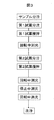
- FIG. 3 shows an example of an analysis operation sequence according to the present invention.
- the cell After dispensing the sample into the cell, dispense the first reagent and stir. Thereafter, the data measured during rotation of the cell disk is stored as rotating photometry data, and then the second reagent is dispensed and stirred. The photometry is performed again while the cell disk is rotating to obtain the photometry data during the rotation. However, the cell is controlled to stop at the midway photometry position, and the data measured during the stop is added to the rotated data as reaction process data. Finally, the reaction solution is discharged from the cell and washed at the washing position.
- Fig. 4 shows the reaction process data in the flow of Fig. 3 together with the analysis operation sequence.
- the photometric data is measured while rotating the cell disk. The difference from a normal sample analyzer is that the data measured during stoppage is added to the rotated data.
- photometry is performed during rotation after dispensing and stirring of the second reagent, and photometry is performed during stoppage.
- Patent Document 2 discloses a technique for driving at high speed for a fixed time during rotation. In this case, however, there is a problem that the reproducibility is lowered because the photometric time per one time is short. Does not decrease reproducibility.
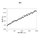
- Fig. 5 shows an example of metering data during stoppage.
- a CRP reagent Naopia CRP, manufactured by Sekisui Chemical Co., Ltd.
- a CRP calibrator produced by Sekisui Chemical Co., Ltd.
- the absorbance change amount data during the reaction can be acquired, and the calibration curve data can be acquired only from the stopped photometric data, and the sample can be quantified.
- a calibration curve obtained by plotting the average value of 100 times together with the photometry data during rotation may be held in the data storage unit.
- the error of the measurement unit can be reduced to 1/10 than the result of one measurement.
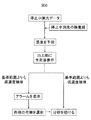
- the amount of components obtained by quantifying the obtained photometric data during stoppage using these calibration curves is displayed on the screen. Since the concentration obtained from the absorbance gradient of photometry during the stop can output the result before the entire reaction is completed, the measurement time is shortened. This flow is shown in FIG. When a concentration exceeding the reference range is obtained, there is a need to know early because re-examination and treatment are performed, so it is useful to output the result as a predicted value before the end of all reactions.
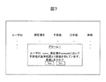
- the amount of components calculated from photometric data during stoppage is outside the preset reference range, sample analysis is performed at an earlier time than normal analysis by displaying an alarm on the screen and prompting reexamination.
- the operator of the apparatus can be notified, and the efficiency of the laboratory can be improved.
- the reference range may be stored in advance in the data storage unit, or may be input from the input unit by the user. A screen diagram is shown in FIG.
- the normal CRP item is usually quantified by the difference between the photometric data once at 45 seconds and after 300 seconds after the second reagent is mixed.
- the noise of the measurement unit can be quantified to be reduced to 1/10 of the data measured once, leading to improved reproducibility.
- the stop time may be extended in a specific item.
- the data storage unit may hold data for changing the time for photometry during the stop according to the component to be measured and the amount of the sample, or may be set by the user from the input unit. .
- the same effect can be obtained at any time from the mixing of the reagent and the sample to the washing, but the reaction with the reagent is not stable due to uneven mixing for 30 seconds after mixing, and the reaction of the reaction after 1 minute or more Since the change in absorbance is small, it is possible to obtain highly reproducible data more quickly by measuring the light during the period from 30 seconds to 1 minute after mixing the last reagent among the reagents to be added. Can do.
- the time timing may be stored in the data storage unit, or may be set by the user from the input unit. As described above, it is possible to follow the same change in specific time for all the cells by measuring with the same measuring unit as that used for measuring during rotation, so that the predicted value can be calculated quickly. Therefore, it can contribute to the improvement of the convenience of the examination room.
Landscapes
- Physics & Mathematics (AREA)
- Chemical & Material Sciences (AREA)
- General Physics & Mathematics (AREA)
- Immunology (AREA)
- Life Sciences & Earth Sciences (AREA)
- Analytical Chemistry (AREA)
- Biochemistry (AREA)
- General Health & Medical Sciences (AREA)
- Pathology (AREA)
- Health & Medical Sciences (AREA)
- Chemical Kinetics & Catalysis (AREA)
- Engineering & Computer Science (AREA)
- Mathematical Physics (AREA)
- Theoretical Computer Science (AREA)
- Spectroscopy & Molecular Physics (AREA)
- Automatic Analysis And Handling Materials Therefor (AREA)
- Investigating Or Analysing Materials By The Use Of Chemical Reactions (AREA)
Abstract
Description
Claims (7)
- サンプルと試薬とが混合した反応液を保持するセルと、
前記セルが円周状に配置され回転と停止を繰り返すセルディスクと、
前記セルディスクの駆動をする駆動部と、
前記反応液に光を照射した結果得られる光を測定する測定部と、
前記セル内の前記反応液を排出しセルを洗浄する洗浄部と、
データを保持するデータ格納部と、
前記測定部により測定したデータを基に前記サンプル内の成分量を分析するデータ処理部と、
前記データ処理部による結果を出力する出力部とを有し、
前記駆動部は、前記サンプルと前記試薬とを混合してから、前記洗浄部にて反応液を排出するまでの間に、前記セルディスクの回転と停止を繰り返し、前記測定部の測光位置に少なくとも一度停止させ、前記測定部は、前記セルディスクが回転中及び停止中に前記反応液を測定することを特徴とするサンプル分析装置。 - 請求項1記載のサンプル分析装置において、前記測定部は、前記セルディスクが停止中に測光し、得られたデータの時間変化量をデータ格納部に格納し、前記データ処理部は、前記サンプル内の成分量を定量することを特徴とするサンプル分析装置。
- 請求項1記載のサンプル分析装置において、前記測定部は、前記セルディスク停止中に複数回測光し、前記データ処理部は、その平均値と回転中に測定した測定値から前記サンプル内の成分量を定量することを特徴とするサンプル分析装置。
- 請求項1記載のサンプル分析装置において、前記データ格納部は、前記セルディスク停止中に前記測定部にて測定したデータから得た停止中検量線と、前記セルディスク回転中に前記測定部にて測定したデータから得た回転中検量線の両方保持しており、前記データ処理部は、前記停止中検量線と前記回転中検量線を用い、前記サンプル内の成分量を定量することを特徴とするサンプル分析装置。
- 請求項1記載のサンプル分析装置において、前記データ格納部は、前記停止中に測光する時間を前記サンプルの測定する成分に応じて変更する、サンプルと停止時間との関係データを保持することを特徴としたサンプル分析装置。
- 請求項1記載のサンプル分析装置において、前記出力部は、前記反応液を保持した前記セルが停止中に、前記データ処理部による定量分析結果を画面に表示することを特徴とするサンプル分析装置。
- 請求項1記載のサンプル分析装置において、前記データ処理部による成分量の結果が、前記データ格納部に格納したあらかじめ設定した基準範囲データ外に位置した場合に、前記出力部は、画面にアラーム表示をする機能を備えたサンプル分析装置。
Priority Applications (3)
| Application Number | Priority Date | Filing Date | Title |
|---|---|---|---|
| CN201080005049.6A CN102292644B (zh) | 2009-03-25 | 2010-03-01 | 样本分析装置 |
| US13/147,809 US8709345B2 (en) | 2009-03-25 | 2010-03-01 | Sample analyzing device |
| DE112010001341T DE112010001341B4 (de) | 2009-03-25 | 2010-03-01 | Probenanalyseneinrichtung |
Applications Claiming Priority (2)
| Application Number | Priority Date | Filing Date | Title |
|---|---|---|---|
| JP2009073098A JP5380123B2 (ja) | 2009-03-25 | 2009-03-25 | サンプル分析装置 |
| JP2009-073098 | 2009-03-25 |
Publications (1)
| Publication Number | Publication Date |
|---|---|
| WO2010109772A1 true WO2010109772A1 (ja) | 2010-09-30 |
Family
ID=42780472
Family Applications (1)
| Application Number | Title | Priority Date | Filing Date |
|---|---|---|---|
| PCT/JP2010/001351 Ceased WO2010109772A1 (ja) | 2009-03-25 | 2010-03-01 | サンプル分析装置 |
Country Status (5)
| Country | Link |
|---|---|
| US (1) | US8709345B2 (ja) |
| JP (1) | JP5380123B2 (ja) |
| CN (1) | CN102292644B (ja) |
| DE (1) | DE112010001341B4 (ja) |
| WO (1) | WO2010109772A1 (ja) |
Cited By (1)
| Publication number | Priority date | Publication date | Assignee | Title |
|---|---|---|---|---|
| JP2013152215A (ja) * | 2012-01-25 | 2013-08-08 | F. Hoffmann-La Roche Ag | 液体試料中の分析物を検出する発光法及び分析システム |
Families Citing this family (4)
| Publication number | Priority date | Publication date | Assignee | Title |
|---|---|---|---|---|
| JP5585362B2 (ja) | 2010-10-01 | 2014-09-10 | 日産自動車株式会社 | 充電ポート用カバーの配設構造 |
| WO2012120755A1 (ja) * | 2011-03-04 | 2012-09-13 | 株式会社 日立ハイテクノロジーズ | 分析装置 |
| JP5948173B2 (ja) * | 2012-07-20 | 2016-07-06 | 株式会社日立ハイテクノロジーズ | 自動分析装置及び自動分析方法 |
| CN113163069B (zh) * | 2021-04-29 | 2023-04-21 | 成都微宇科技有限责任公司 | 一种航摄方法、装置、航摄仪及航摄系统 |
Citations (5)
| Publication number | Priority date | Publication date | Assignee | Title |
|---|---|---|---|---|
| JPS5782769A (en) * | 1980-11-10 | 1982-05-24 | Hitachi Ltd | Automatic analyzing device |
| JPS61218949A (ja) * | 1985-03-25 | 1986-09-29 | Hitachi Ltd | 自動分析装置 |
| JP2666568B2 (ja) * | 1990-12-29 | 1997-10-22 | 株式会社島津製作所 | 生化学自動分析装置 |
| JP2001208760A (ja) * | 2000-01-27 | 2001-08-03 | Jeol Ltd | 複合生化学・免疫自動分析装置 |
| JP2001235422A (ja) * | 2000-02-22 | 2001-08-31 | Toshiba Corp | 自動分析装置 |
Family Cites Families (9)
| Publication number | Priority date | Publication date | Assignee | Title |
|---|---|---|---|---|
| JPS5868670A (ja) * | 1981-10-21 | 1983-04-23 | Hitachi Ltd | 自動分折装置 |
| JPS5924380B2 (ja) * | 1982-09-27 | 1984-06-08 | 株式会社日立製作所 | 化学分析装置 |
| JP2708437B2 (ja) * | 1987-11-13 | 1998-02-04 | 株式会社日立製作所 | 自動分析装置 |
| JPH0249141A (ja) * | 1988-05-09 | 1990-02-19 | Cosmo Oil Co Ltd | スラッジ濃度迅速定量方法および装置 |
| JP2845248B2 (ja) * | 1991-10-28 | 1999-01-13 | 株式会社島津製作所 | 血液凝固測定装置 |
| US5518923A (en) * | 1995-06-06 | 1996-05-21 | Becton Dickinson And Company | Compact blood culture apparatus |
| US6723288B2 (en) * | 2002-04-29 | 2004-04-20 | Dade Behring Inc. | Method of providing assay processing in a multi-analyzer system |
| JP2004251802A (ja) * | 2003-02-21 | 2004-09-09 | Toshiba Corp | 自動分析装置 |
| JP4221349B2 (ja) | 2004-09-17 | 2009-02-12 | 株式会社日立ハイテクノロジーズ | 自動分析装置 |
-
2009
- 2009-03-25 JP JP2009073098A patent/JP5380123B2/ja active Active
-
2010
- 2010-03-01 CN CN201080005049.6A patent/CN102292644B/zh not_active Expired - Fee Related
- 2010-03-01 DE DE112010001341T patent/DE112010001341B4/de not_active Expired - Fee Related
- 2010-03-01 WO PCT/JP2010/001351 patent/WO2010109772A1/ja not_active Ceased
- 2010-03-01 US US13/147,809 patent/US8709345B2/en active Active
Patent Citations (5)
| Publication number | Priority date | Publication date | Assignee | Title |
|---|---|---|---|---|
| JPS5782769A (en) * | 1980-11-10 | 1982-05-24 | Hitachi Ltd | Automatic analyzing device |
| JPS61218949A (ja) * | 1985-03-25 | 1986-09-29 | Hitachi Ltd | 自動分析装置 |
| JP2666568B2 (ja) * | 1990-12-29 | 1997-10-22 | 株式会社島津製作所 | 生化学自動分析装置 |
| JP2001208760A (ja) * | 2000-01-27 | 2001-08-03 | Jeol Ltd | 複合生化学・免疫自動分析装置 |
| JP2001235422A (ja) * | 2000-02-22 | 2001-08-31 | Toshiba Corp | 自動分析装置 |
Cited By (1)
| Publication number | Priority date | Publication date | Assignee | Title |
|---|---|---|---|---|
| JP2013152215A (ja) * | 2012-01-25 | 2013-08-08 | F. Hoffmann-La Roche Ag | 液体試料中の分析物を検出する発光法及び分析システム |
Also Published As
| Publication number | Publication date |
|---|---|
| US20110293476A1 (en) | 2011-12-01 |
| DE112010001341B4 (de) | 2013-10-17 |
| JP2010223845A (ja) | 2010-10-07 |
| JP5380123B2 (ja) | 2014-01-08 |
| US8709345B2 (en) | 2014-04-29 |
| CN102292644B (zh) | 2014-09-03 |
| DE112010001341T5 (de) | 2012-07-05 |
| CN102292644A (zh) | 2011-12-21 |
Similar Documents
| Publication | Publication Date | Title |
|---|---|---|
| US20240272186A1 (en) | Automatic analyzer | |
| JP2024169609A (ja) | 自動分析装置及び自動分析方法 | |
| JP4006203B2 (ja) | 自動分析装置及び化学分析方法の精度管理方法 | |
| JP6814171B2 (ja) | 自動分析装置 | |
| JP5380123B2 (ja) | サンプル分析装置 | |
| JP6464026B2 (ja) | 自動分析装置 | |
| WO2011090173A1 (ja) | 自動分析装置 | |
| WO2007119785A1 (ja) | 自動分析装置の分析支援用液体の品質管理方法および自動分析装置 | |
| JP6576843B2 (ja) | 自動分析装置及びその散乱光測定光学系評価用標準液 | |
| CN101344530A (zh) | 自动分析装置以及自动分析装置的分析方法 | |
| JP5271929B2 (ja) | 自動分析装置 | |
| JP7520613B2 (ja) | 自動分析装置 | |
| JP6745407B2 (ja) | 自動分析装置 | |
| JP2022118402A (ja) | 標準試料容器及び自動分析装置 | |
| JP3127156U (ja) | 自動分析装置 | |
| JP4825442B2 (ja) | 臨床検査用自動分析装置の精度管理方法、及び自動分析装置 | |
| JP2026032482A (ja) | 自動分析装置 | |
| CN117295955A (zh) | 自动分析装置以及检体分析方法 | |
| JP2008203005A (ja) | 自動分析装置 | |
| CN117849379A (zh) | 样本分析仪及样本分析仪的控制方法 | |
| CN117805424A (zh) | 样本分析仪及样本分析仪的控制方法 | |
| CN119585607A (zh) | 自动分析装置 | |
| WO2022138249A1 (ja) | 自動分析装置および分析方法 | |
| JP2010085275A (ja) | 自動分析装置 | |
| JP2009243995A (ja) | 自動分析装置 |
Legal Events
| Date | Code | Title | Description |
|---|---|---|---|
| WWE | Wipo information: entry into national phase |
Ref document number: 201080005049.6 Country of ref document: CN |
|
| 121 | Ep: the epo has been informed by wipo that ep was designated in this application |
Ref document number: 10755579 Country of ref document: EP Kind code of ref document: A1 |
|
| WWE | Wipo information: entry into national phase |
Ref document number: 13147809 Country of ref document: US |
|
| WWE | Wipo information: entry into national phase |
Ref document number: 1120100013411 Country of ref document: DE Ref document number: 112010001341 Country of ref document: DE |
|
| 122 | Ep: pct application non-entry in european phase |
Ref document number: 10755579 Country of ref document: EP Kind code of ref document: A1 |