WO2010109656A1 - 開離嵌挿具付きスライドファスナー - Google Patents
開離嵌挿具付きスライドファスナー Download PDFInfo
- Publication number
- WO2010109656A1 WO2010109656A1 PCT/JP2009/056330 JP2009056330W WO2010109656A1 WO 2010109656 A1 WO2010109656 A1 WO 2010109656A1 JP 2009056330 W JP2009056330 W JP 2009056330W WO 2010109656 A1 WO2010109656 A1 WO 2010109656A1
- Authority
- WO
- WIPO (PCT)
- Prior art keywords
- tape
- fitting
- pivot
- fastener
- box
- Prior art date
Links
- 238000003780 insertion Methods 0.000 claims description 81
- 230000037431 insertion Effects 0.000 claims description 81
- 238000000926 separation method Methods 0.000 description 42
- 238000000034 method Methods 0.000 description 9
- 238000009958 sewing Methods 0.000 description 8
- 238000005192 partition Methods 0.000 description 5
- 238000005452 bending Methods 0.000 description 4
- 229920003002 synthetic resin Polymers 0.000 description 4
- 239000000057 synthetic resin Substances 0.000 description 4
- 210000000078 claw Anatomy 0.000 description 3
- 238000001746 injection moulding Methods 0.000 description 3
- 230000002452 interceptive effect Effects 0.000 description 3
- 230000002093 peripheral effect Effects 0.000 description 3
- 230000002787 reinforcement Effects 0.000 description 3
- 230000013011 mating Effects 0.000 description 2
- 229930182556 Polyacetal Natural products 0.000 description 1
- 239000004952 Polyamide Substances 0.000 description 1
- 230000007547 defect Effects 0.000 description 1
- 238000010586 diagram Methods 0.000 description 1
- 230000000694 effects Effects 0.000 description 1
- 238000012986 modification Methods 0.000 description 1
- 230000004048 modification Effects 0.000 description 1
- 238000000465 moulding Methods 0.000 description 1
- 229920002647 polyamide Polymers 0.000 description 1
- 229920006324 polyoxymethylene Polymers 0.000 description 1
- 238000009751 slip forming Methods 0.000 description 1
- 229920005992 thermoplastic resin Polymers 0.000 description 1
- 230000009466 transformation Effects 0.000 description 1
- 238000003466 welding Methods 0.000 description 1
Images


Classifications
-
- A—HUMAN NECESSITIES
- A44—HABERDASHERY; JEWELLERY
- A44B—BUTTONS, PINS, BUCKLES, SLIDE FASTENERS, OR THE LIKE
- A44B19/00—Slide fasteners
- A44B19/24—Details
- A44B19/36—Means for permanently uniting the stringers at the end; Means for stopping movement of slider at the end
-
- A—HUMAN NECESSITIES
- A44—HABERDASHERY; JEWELLERY
- A44B—BUTTONS, PINS, BUCKLES, SLIDE FASTENERS, OR THE LIKE
- A44B19/00—Slide fasteners
- A44B19/24—Details
- A44B19/38—Means at the end of stringer by which the slider can be freed from one stringer, e.g. stringers can be completely separated from each other
- A44B19/382—"Two-way" or "double-acting" separable slide fasteners
-
- A—HUMAN NECESSITIES
- A44—HABERDASHERY; JEWELLERY
- A44B—BUTTONS, PINS, BUCKLES, SLIDE FASTENERS, OR THE LIKE
- A44B19/00—Slide fasteners
- A44B19/24—Details
- A44B19/26—Sliders
-
- A—HUMAN NECESSITIES
- A44—HABERDASHERY; JEWELLERY
- A44B—BUTTONS, PINS, BUCKLES, SLIDE FASTENERS, OR THE LIKE
- A44B19/00—Slide fasteners
- A44B19/24—Details
- A44B19/38—Means at the end of stringer by which the slider can be freed from one stringer, e.g. stringers can be completely separated from each other
-
- A—HUMAN NECESSITIES
- A44—HABERDASHERY; JEWELLERY
- A44B—BUTTONS, PINS, BUCKLES, SLIDE FASTENERS, OR THE LIKE
- A44B19/00—Slide fasteners
- A44B19/10—Slide fasteners with a one-piece interlocking member on each stringer tape
- A44B19/12—Interlocking member in the shape of a continuous helix
-
- Y—GENERAL TAGGING OF NEW TECHNOLOGICAL DEVELOPMENTS; GENERAL TAGGING OF CROSS-SECTIONAL TECHNOLOGIES SPANNING OVER SEVERAL SECTIONS OF THE IPC; TECHNICAL SUBJECTS COVERED BY FORMER USPC CROSS-REFERENCE ART COLLECTIONS [XRACs] AND DIGESTS
- Y10—TECHNICAL SUBJECTS COVERED BY FORMER USPC
- Y10T—TECHNICAL SUBJECTS COVERED BY FORMER US CLASSIFICATION
- Y10T24/00—Buckles, buttons, clasps, etc.
- Y10T24/25—Zipper or required component thereof
- Y10T24/2518—Zipper or required component thereof having coiled or bent continuous wire interlocking surface
-
- Y—GENERAL TAGGING OF NEW TECHNOLOGICAL DEVELOPMENTS; GENERAL TAGGING OF CROSS-SECTIONAL TECHNOLOGIES SPANNING OVER SEVERAL SECTIONS OF THE IPC; TECHNICAL SUBJECTS COVERED BY FORMER USPC CROSS-REFERENCE ART COLLECTIONS [XRACs] AND DIGESTS
- Y10—TECHNICAL SUBJECTS COVERED BY FORMER USPC
- Y10T—TECHNICAL SUBJECTS COVERED BY FORMER US CLASSIFICATION
- Y10T24/00—Buckles, buttons, clasps, etc.
- Y10T24/25—Zipper or required component thereof
- Y10T24/2593—Zipper or required component thereof including complementary, aligning means attached to ends of interlocking surfaces
- Y10T24/2595—Zipper or required component thereof including complementary, aligning means attached to ends of interlocking surfaces having specific mounting connection or reinforcing structure at connection
-
- Y—GENERAL TAGGING OF NEW TECHNOLOGICAL DEVELOPMENTS; GENERAL TAGGING OF CROSS-SECTIONAL TECHNOLOGIES SPANNING OVER SEVERAL SECTIONS OF THE IPC; TECHNICAL SUBJECTS COVERED BY FORMER USPC CROSS-REFERENCE ART COLLECTIONS [XRACs] AND DIGESTS
- Y10—TECHNICAL SUBJECTS COVERED BY FORMER USPC
- Y10T—TECHNICAL SUBJECTS COVERED BY FORMER US CLASSIFICATION
- Y10T24/00—Buckles, buttons, clasps, etc.
- Y10T24/25—Zipper or required component thereof
- Y10T24/2596—Zipper or required component thereof including means attaching interlocking surfaces together
Definitions
- the present invention relates to a slide fastener provided with a separation / insertion tool, and in particular, the separation / insertion tool includes a fitting body and a pivoting body, and the fitting body has two types of engagement with the pivoting body.
- the present invention relates to a slide fastener with a separation / insertion tool having a structure that can be locked by a stopping operation.
- Patent Document 1 Japanese Patent Application Laid-Open No. 2008-43568
- Patent Document 1 has improved the ease of use of the open / close insert for a slide fastener having such a side open type open / close insert.
- a slide fastener is disclosed.
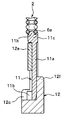
- the slide fastener 61 with the separation fitting 62 described in Patent Document 1 has a plurality of individual fastener elements 64 made of synthetic resin arranged in a row on the left and right fastener tapes 63.
- the fastener element 64 is formed in a predetermined shape by performing injection molding on the fastener tape 63. Further, as a slider inserted into the element row 65 composed of such fastener elements 64, a conventionally known general slider can be used.
- the opening / closing insertion tool 62 is formed continuously with the element row 65, and is arranged at the lower end of the left fastener tape 63, and has an insertion body 67 serving as a butterfly pin, and a right fastener tape 63. And a pivoting body 68 serving as a box bar and a box body.
- the fitting body 67 is taped at a thin plate-like fitting plate portion 67a fixed to both front and back surfaces of the left fastener tape 63, and a tip end portion (rear end portion) of the fitting plate portion 67a on the tape end side.
- fitting plate portion 67a is flat on both the front and back surfaces except for the recessed portion 67e, and the thickness in the tape front and back direction is formed smaller than the gap between the upper and lower flanges of the slider. Further, the fitting plate portion 67a is provided with a notch portion 67f cut into the tape inward from the tape end side.
- the pivot body 68 is formed thicker via a slider holding portion (box bar portion) 68a formed on both front and back surfaces of the right fastener tape 63 and a step portion 68b than the slider holding portion 68a.
- a pivot stop (box body) 68c having a substantially J-shape, and a reinforcement 68d formed inside the tape from the slider holding portion 68a to enhance the fixing strength of the pivot 68 to the fastener tape 63. have.
- a groove 68e is formed.
- the fitting body facing side edge of the slider holding portion 68 a is curved so that the intermediate portion slightly bulges toward the fitting body 67.
- the slider holding portion 68a can be inserted into the element guide path of the slider and hold the slider when the slider is slid and brought into contact with the stepped portion 68b.
- the pivoting portion 68c is fitted into the pivoting space 68f and a pivoting space 68f that opens upward so that the pivoted portion 67b of the fitting body 67 can be detached from the side of the pivoting member 68.
- an inner peripheral surface 68g that can be rotatably locked by abutting the pivoted portion 67b.
- a slit 68h is formed from the inner peripheral surface 68g to the outer peripheral surface at the distal end portion of the pivot stop portion 68c, and the groove width in the tape front and back direction of the slit 68h is the thickness of the fitting plate portion 67a. Is set larger than.
- the fitting body 67 is rotated toward the pivoted body 68 around the pivoted portion 67 b, whereby the fitting body 67.
- the fitting plate portion 67a is inserted into the element guide path via a tape groove provided between the upper and lower flanges of the slider.
- the meshing portion (saddle portion) 67d of the fitting body 67 is engaged with the fastener element 64 adjacent to the pivoting body 68, and
- the left and right element rows 65 can be engaged with each other in order from the end on the side of the opening / closing insertion tool 62.
- the pivoted portion 67b of the fitting 67 is pivoted from the shoulder of the slider via the element guide path of the slider. Also by being inserted into the body 68, the pivoted portion 67b is rotatably locked to the pivoted portion 68c of the pivoted body 68. Thereafter, by sliding the slider in the meshing direction along the element rows 65, the left and right element rows 65 can be meshed in the same manner as described above.
- a synthetic resin single fastener element 64 formed by injection molding is disposed across the tape front and back surfaces of the fastener tape 63. Further, each individual fastener element 64 has a symmetrical shape with respect to the fastener tape 63. Therefore, in the slide fastener 61, when the left and right element rows 65 are engaged, the left and right fastener elements 64 are firmly engaged on both the tape front surface side and the tape back surface side of the fastener tape 63.
- the fitting body 67 and the pivoting body 68 that form the opening / closing insertion tool 62 are also formed in a symmetrical shape across the tape front and back surfaces of the fastener tape 63, similarly to the fastener element 64.
- the fitting body 67 and the pivoting body 68 can easily secure the thickness in the tape front and back direction. For example, even if the separation fitting 62 receives a push-up force in the tape front and back direction, The body 67 and the pivoting body 68 are not easily bent.
- each fastener element 64 is fixed across the tape front and back surfaces of the fastener tape 63.
- the slide fastener is inferior in flexibility as compared with a slide fastener in which the element row is formed of a continuous fastener element having a coil shape or a zigzag shape.
- the separation fastener has a fitting body and a pivoting body as disclosed in Patent Document 1, and different 2
- a separable fitting that can lock the fitting body to the pivoting body by a type of locking operation
- the separable fitting is subjected to push-up force, it meshes with the element row. There has been a problem that it is likely to occur.
- the left and right continuous fastener elements are sewn using a sewing thread on one surface (upper surface) side of the fastener tape, whereby an element array Is formed.
- the slider used in the slide fastener is provided with upper and lower flanges on the left and right side edges of the upper and lower blades, and a tape groove for inserting a fastener tape is provided between the upper and lower flanges. .
- the vertical height position of the tape groove is the upper and lower wing plate. It is set and formed on the lower blade side than the central part in between.
- this tape groove maintains the posture of the continuous fastener element appropriately and stably meshes the left and right continuous fastener elements, for example, compared with the case where the element row is formed by the single fastener element 64, for example.
- the groove width is narrowed.
- the slide fastener having such a continuous fastener element is provided with the separation fitting insert 62 having the fitting body 67 and the pivoting body 68 as shown in FIG.
- the fitting plate portion 67a needs to be formed so that its height dimension (thickness) in the tape front and back direction is thin enough to be inserted into the tape groove of the slider. Further, in this case, since the distance between the tape groove of the slider and the lower wing plate is narrower than the interval between the tape groove and the upper wing plate, the thickness on the tape back surface side of the fitting plate portion 67a is larger than that on the tape surface side. I had to make it thinner.
- the thickness of the fitting plate portion 67a of the fitting body 67 is set thin as described above, in order to reduce the rigidity of the fitting plate portion 67a, for example, in a state where the element row of the slide fastener is engaged.
- the separation / insertion tool 62 receives a lateral pulling force in the tape width direction or a push-up force in the tape front / back direction, the insertion plate portion 67a is easily bent so as to shrink in the tape front / back direction.
- the insertion plate portion 67a is thinner on the tape back side than on the tape surface side, the insertion plate portion 67a is easily bent so as to bend in a convex shape toward the tape back side when subjected to a lateral pulling force or a push-up force.
- a specific object of the present invention is that the element row is formed by a continuous fastener element having a coil shape or a zigzag shape, and is fitted in two types of operations. Is provided so that the engagement state of the element row can be stably maintained even if the separation / insertion tool receives a lateral pulling force or a pushing-up force.
- An object of the present invention is to provide a slide fastener with an opening / closing insert.
- a slide fastener with a break-and-fit insert is a coil-like or zigzag-like continuous fastener element attached to opposite tape side edges of a pair of left and right fastener tapes.
- a slider is inserted into the element row consisting of: an insertion body fixed to one end of one of the element rows; and a pivotal body fixed to one end of the other element row; And a thin plate-like fitting plate portion fixed to the tape front and back surfaces of the fastener tape and having a first surface and a second surface, and projecting from an end portion of the fitting plate portion opposite to the element row.
- the pivot body has a first surface and a second surface, and the pivot body extends from the end of the element row to the tape end side along the tape length direction.
- the box that holds the slider And a box part extending from the box bar part, the box part being capable of engaging and disengaging the pivot part from the side of the pivotal support and formed in the slider A slide fastener with a separable fitting insert having a substantially J-shape that can be engaged and disengaged via an element guide path, wherein the pivot portion projects only on the first surface of the fitting plate portion.
- the pivoting body extends from the first surface side of the box bar portion toward the outside of the tape, and supports a first surface side of the fitting plate portion when the element row is engaged.
- a flat plate-like support portion that extends from the second surface side of the box body portion toward the outside of the tape and supports the second surface side of the fitting plate portion when the element row is engaged. Is the main feature.
- the box part extends from the box bar part through a step part, and the flat plate-like support part has the step part in the tape length direction. Is disposed closer to the box body than the position, and closer to the element row side than the pivot shaft locked to the pivot, and the outer side of the pivot body side of the box in the tape width direction. It is preferable that the taper is disposed on the inner side of the wall surface and on the outer side of the tape with respect to the pivot portion locked to the pivot support body.
- the fitting body has a meshing portion that meshes with the continuous fastener element on the meshing counterpart side at a base end portion on the element row side of the fitting plate portion, and the element row includes the continuous fastener element. It is preferable that the core string is sewn with the core string inserted therethrough, and one end of the core string is embedded in the meshing portion.
- the meshing portion includes a protrusion protruding toward the element row, and the protrusion is formed closer to the first surface side of the fitting plate portion.
- the flat plate-like support portion supports an end region including the second surface side of the end portion where the pivot portion of the fitting plate portion is formed.
- the left and right element rows are formed of continuous fastener elements having a coil shape or a zigzag shape, and the fitting body is fixed to one end of one element row. And a pivot member fixed to one end of the other element row.
- the insertion body is fixed to the tape front and back surfaces of the fastener tape, and protrudes only on the thin plate-like insertion plate portion having the first surface and the second surface, and the first surface of the insertion plate portion.
- a pivot part The pivot body has a first surface and a second surface, and the pivot body extends from the end of the element row to the tape end side along the tape length direction and holds the slider.
- a box bar part a substantially J-shaped box part extending from the box bar part, and extending parallel to the fitting plate part from the first surface side of the box bar part toward the outside of the tape
- a flat plate-like support portion extending in parallel with the fitting plate portion from the second surface side of the box portion toward the outside of the tape.
- Such a slide fastener with a separation / insertion tool of the present invention is excellent in flexibility because the element row is formed of a continuous fastener element having a coil shape or a zigzag shape. Moreover, since the pivot part is protrudingly provided only on the first surface of the fitting plate part, the slide fastener is provided with a flat plate-like support part on the second surface side of the box part in the pivotal support body. The flat plate-like support portion can be prevented from interfering with the fitting when the fitting is locked to the pivotal support.
- the first surface side of the fitting body is supported by the projecting piece portion of the pivot body,
- a flat plate-like support portion supports the second surface side of the fitting plate portion.
- the projecting piece of the pivotal body is fitted when the separation / insertion tool composed of the insertion body and the pivotal body receives a lateral pulling force in the tape width direction or a pushing force in the tape front / back direction.
- the first surface side of the plate portion is supported, and it is possible to prevent the fitting plate portion from bending so as to be convexly curved toward the tape surface side, and the flat plate-like support portion of the pivotal support member is the fitting plate portion.
- the second plate side is supported, and the fitting plate portion can be prevented from being bent so as to be convex toward the tape rear surface side.
- the opening / closing insertion tool receives a lateral pulling force or a pushing force, the relative position relationship between the inserting body and the pivotal support body is stabilized in order to prevent the inserting plate portion from bending and bending. Further, it is possible to prevent the occurrence of meshing cracks from the end portion on the side of the separation / insertion tool in the element row, thereby stably maintaining the meshing state of the element row.
- the box part extends from the box bar part via a step part, and the flat plate-like support part extends in the tape length direction. It is arranged on the box body side with respect to the position of the step part, and on the element row side with respect to the pivot part locked to the pivot body, and on the pivot body side of the box body in the tape width direction. It is arranged on the inner side of the position of the outer wall surface and on the outer side of the tape than the pivot portion locked to the pivot support body. Thereby, the 2nd surface side of an insertion board part can be supported more stably by the flat support part of a pivotal support body, and it can prevent more effectively that an insertion board part bends.
- the fitting body meshes with the base fastener portion on the element row side of the fitting plate portion to mesh with the continuous fastener element on the meshing counterpart side.
- the element row is sewn in a state where a core string is inserted into the continuous fastener element, and one end of the core string is embedded in the meshing portion.
- one end of the core string inserted into the continuous fastener element is embedded in the meshing portion of the insertion body, and the core string is cut off from the insertion plate portion. ing.
- the continuous fastener element can be stably attached to the fastener tape, and the fitting plate portion can be formed thinner, so that the operation of inserting the fitting plate portion into the tape groove of the slider can be performed. It can be carried out smoothly and stably.
- the meshing portion includes a protrusion protruding toward the element row, and the protrusion is formed closer to the first surface side of the fitting plate portion.
- the protrusion provided in the meshing portion can be easily engaged with the element row on the side where the pivotal support is formed, and thereby the meshing strength of the left and right element rows can be improved.
- the flat plate-like support portion is the pivot of the fitting plate portion.
- An end region including the second surface side of the end portion where the portion is formed is supported.
- FIG. 1 is a front view showing a slide fastener with a break-fitting insert according to Embodiment 1 of the present invention.
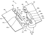
- FIG. 2 is a perspective view which shows the insertion body and pivoting body of the separation fitting which are distribute
- FIG. 3 is a rear view of the fitting body and the pivotal support body of the separation / insertion tool.
- FIG. 4 is a cross-sectional view showing a state in which the pivot portion of the fitting body is locked to the pivot body.
- FIG. 5 is a cross-sectional view showing a state where the fitting body is locked to the pivotal support body and the fitting plate portion of the fitting body is inserted into the tape groove of the slider.
- FIG. 1 is a front view showing a slide fastener with a break-fitting insert according to Embodiment 1 of the present invention.
- FIG. 2 is a perspective view which shows the insertion body and pivoting body of the separation fitting which are distribute
- FIG. 6 is a front view showing a state in which the left and right element rows are engaged with each other.
- 7 is a cross-sectional view taken along line VII-VII shown in FIG.
- FIG. 8 is an explanatory view for explaining the movement of the pivot portion when the slide fastener is opened.
- FIG. 9 is a front view which shows the pivotal support body of the slide fastener with a separation fitting insert which concerns on Example 2 of this invention.
- FIG. 10 is a perspective view showing a conventional slide fastener with a separation / insertion tool.
- coil-like continuous fastener elements are sewn on the side edges of the left and right fastener tapes to form an element row.
- an element row may be formed by sewing a zigzag continuous fastener element on the tape side edge of the fastener tape.
- FIG. 1 is a front view showing a slide fastener with a break-away insert according to the first embodiment.
- FIG. 2 is a perspective view showing a fitting body and a pivotal body of a separation fitting inserted in the slide fastener
- FIG. 3 is a perspective view of the fitting body and the pivoting body of the separation fitting. It is a rear view.
- FIG. 4 is a cross-sectional view showing a state in which the pivot portion of the fitting body is locked to the pivotal support body
- FIG. 5 is a diagram illustrating the state in which the fitting body is locked to the pivotal support body. It is sectional drawing which shows the state which inserted the insertion board part in the tape groove
- FIG. 6 is a front view which shows the state which meshed the element row
- illustration of a sewing thread for sewing a continuous fastener element on the fastener tape is omitted.
- the tape length direction of the fastener tape is the front-rear direction (the side on which the top stopper is disposed is the front, and the side on which the separation fitting is disposed)
- the tape width direction is the left-right direction (left side when viewed from the front, the right side is the right side), and the tape front / back direction is the vertical direction (continuous fastener elements are arranged with respect to the fastener tape).
- the side that is used is the upper side, and the opposite side is the lower side).
- a slide fastener 1 with a separation / insertion insert includes a pair of left and right fastener stringers 3 on which an element row 2 is formed, and a separation fit attached to one end of the element row 2 of the fastener stringer 3.
- An insertion tool 10 and a slider 4 for engaging and separating the left and right element rows 2 are provided.
- the fastener stringer 3 of the first embodiment is formed by sewing a coil-shaped continuous fastener element 6 on the upper surface side of the opposing tape side edges of the left and right fastener tapes 5.
- each element row 2 of the left and right fastener stringers 3 uses the sewing thread 8 on the upper surface of the fastener tape 5 in the state where the core string 7 is inserted into the coil-like continuous fastener element 6. It is formed by sewing.
- the core string 7 inserted into the right side continuous fastener element 6 extends downward from the lower end of the right side element row 2 and is embedded in a pivotal support 12 (to be described later) of the separation fitting 10.
- the core string 7 inserted into the left continuous fastener element 6 is arranged up to a position of a meshing portion 11c of a fitting body 11 (to be described later) of the separation / insertion tool 10, and the rear end of the concentric string 7 is It is embedded in the meshing part 11c. Therefore, the core string 7 is cut out from the area
- the coiled continuous fastener element 6 is obtained by molding a synthetic resin monofilament into a coil shape.
- the fastener element 6 includes a meshing head that meshes with and disengages from the other fastener element 6, a pair of upper and lower legs extending in one direction (inward of the tape) from the meshing head, and a leg between adjacent elements. And a connecting portion that connects the two.
- arranged upward be an upper leg part
- top stoppers 9 are fixed to the upper ends of the left and right element rows 2. Furthermore, top stoppers 9 are fixed to the upper ends of the left and right element rows 2. Furthermore, the reinforcement part 15 is formed in the lower end part front and back of the tape length direction of the fastener tape 5 by welding a synthetic resin film.
- the slider 4 is the same as the normal slider 4 used in the conventional slide fastener 1 having the coiled continuous fastener element 6.
- the slider 4 includes upper and lower blades 4a and 4b, a connecting column 4c for connecting the upper and lower blades 4a and 4b at the front end of the slider 4, and upper and lower blades provided on the left and right edges of the upper and lower blades 4a and 4b.
- a stop claw 4e disposed on the flange 4d and the upper wing plate 4a and capable of stopping the slider 4 by engaging with the element row 2, and a handle attachment column 4f erected on the surface of the upper wing plate 4a And a handle 4g attached to the handle attachment column 4f.
- shoulder ends are formed on the left and right sides of the connecting column 4c at the end (front end) of the slider 4 on the side where the connecting column 4c is disposed, and the opposite end (rear end) is formed at the opposite end (rear end).
- a rear mouth is formed.
- an element guide path 4 h that communicates with the left and right shoulder openings and the rear opening and has a substantially Y shape in a front view.
- An inner partition (not shown) is formed in the element guide path 4h to stabilize the position of the fastener element 6 passing through the element guide path 4h.
- the partition is an element of the upper and lower blades 4a and 4b. It is comprised by the protrusion part formed in the surface (inner surface) by the side of the guide path 4h.
- a tape groove through which the fastener tape 5 is passed when the slider 4 is slid along the element row 2 is arranged. It is set on the lower blade plate 4b side from the center position in the vertical direction (height direction) between the upper and lower blade plates 4a and 4b.
- the slider 4 is slid by arranging the tape groove of the slider 4 closer to the lower wing plate 4b.
- the distance between the lower blade plate 4b of the slider 4 and the lower surface of the fastener tape 5 can be reduced.
- it can suppress that the continuous fastener element 6 inclines in the direction orthogonal to a tape length direction (rolls) within the element guide path 4h of the slider 4, and can stabilize the attitude
- the separation / insertion tool 10 is molded and integrated with the lower end portion of the fastener tape 5 by injection-molding a thermoplastic resin such as polyacetal or polyamide on the fastener tape 5. It has the fitting body 11 distribute
- a thermoplastic resin such as polyacetal or polyamide
- the insertion body 11 of the opening / closing insertion tool 10 is continuously formed from the lower end edge of the left element row 2 and is formed across the tape front and back surfaces of the fastener tape 5.
- the insertion body 11 includes a thin plate-like insertion plate portion 11 a fixed to the front and back surfaces of the fastener tape 5, and a pivot portion 11 b protruding from a corner portion on the rear end side of the insertion plate portion 11 a.
- a first engaging portion 11c formed on a base end portion (front end portion) on the element row 2 side of the fitting plate portion 11a and a tape inner side edge portion on the front and back surfaces of the fitting plate portion 11a.
- second protrusions 11d and 11e In this case, the front surface (upper surface) of the fitting plate portion 11a is the first surface, and the back surface (lower surface) is the second surface.
- the fitting plate portion 11a in the fitting body 11 is formed in a flat thin plate shape on both the front and back surfaces, and the thickness thereof is the groove width of the tape groove of the slider 4 (interval between the upper and lower flanges 4d). It is set smaller than the size. Furthermore, it is set smaller than the vertical dimension of the element row 2.
- the core string 7 is not arranged on the fitting plate portion 11a in the first embodiment as described above.
- the thickness of the fitting plate portion 11a can be easily made thinner than the groove width of the tape groove, and since the fitting plate portion 11a is not divided by the core string 7, the strength of the fitting plate portion 11a Stiffness can be increased.
- the core string 7 has entered the inside of the meshing part 11c.
- the fitting plate portion 11a is interposed via a tape groove disposed near the lower wing plate 4b of the slider 4 as will be described later. Therefore, the thickness of the lower surface portion disposed on the tape lower surface side is made thinner than the thickness of the upper surface portion disposed on the tape upper surface side of the fitting plate portion 11a. Is formed.
- the pivot part 11b in the fitting body 11 has a tape outer side (pivot support) on the rear end side of the fitting plate part 11a (on the upper surface of the fitting plate part 11a opposite to the element row 2 side).
- a tape outer side pivoted support
- the pivoted support portion 67b pivoted portion
- FIG. 10 sees the upper and lower surfaces of the fitting plate portion 11a.
- the height dimension (thickness) in the tape front and back direction from the lower surface of the fitting plate portion 11a to the upper surface of the pivot portion 11b is smaller than the interval between the upper and lower blade plates 4a and 4b of the slider 4, and the slider 4 is set larger than the tape groove.
- the pivot shaft portion 11b is formed in a substantially cylindrical shape
- the side wall surface of the pivot shaft portion 11b is arranged on the cylindrical surface 11k and the tape inner side of the pivot shaft portion 11b, and is parallel to the tape length direction.
- the said 1st and 2nd protrusion part 11d, 11e in the same insertion body 11 is the state which protruded from the surface and back surface of the same insertion board part 11a, and is formed along the tape inner side edge of the insertion board part 11a. Has been. By forming such 1st and 2nd protrusion part 11d, 11e, the rigidity of the insertion board part 11a can be improved.
- a relief portion 11f is provided so as to be cut out from the side surface on the plate portion 11a side toward the inside of the tape, and the width dimension (the dimension in the tape width direction) at the rear end portions of the first and second protrusions 11d and 11e. ) Is made smaller than the width dimension at the front end.
- the relief portion 11f provided in the second protrusion 11e is formed longer in the tape length direction than the escape portion 11f provided in the first protrusion 11d, and is provided in the second protrusion 11e.
- the front end position of the escape portion 11f is arranged closer to the element row side (front side) than the front end of the escape portion 11f provided in the first protrusion 11d.
- the meshing portion 11c of the fitting body 11 is formed integrally with the fitting plate portion 11a across the tape front and back surfaces of the fastener tape 5. Similarly to the fitting plate portion 11a, the mesh portion 11c is set such that the thickness of the portion disposed on the tape lower surface side of the mesh portion 11c is thinner than the thickness of the portion disposed on the tape upper surface side.
- the meshing portion 11c has a step surface 11g on which the mating fastener element 6 can be placed when the left and right element rows 2 are meshed, and a front side (toward the element row) from the step surface 11g.
- the protrusion 11h of the meshing portion 11c is formed to be deformed from the upper surface side (first surface side) of the thin plate-like fitting plate portion 11a, as shown in FIG.
- the protrusion 11h is formed on the meshing portion 11c as described above, when the left and right element rows 2 are meshed, the upper and lower leg portions of the mating counterpart fastener element 6 placed on the stepped surface 11g.
- the protrusion 11h can be stably inserted therebetween, and the meshing portion 11c and the fastener element 6 can be easily engaged. Thereby, the meshing intensity
- the concave portion 11i is formed in the meshing portion 11c, for example, after the slider 4 is held in a box bar portion 12a described later of the pivotal support body 12, the fitting plate portion of the fitting body 11 is placed in the slider 4.
- the meshing part 11c of the insertion body 11 and the partition provided in the element guide path 4h of the slider 4 interfere with each other.
- the pivotal support body 12 of the separation / insertion tool 10 is formed from the lower end edge of the right element row 2 so as to straddle the tape front and back surfaces of the fastener tape 5.
- the pivotal support body 12 includes a box bar portion 12a formed across the front and back surfaces of the right fastener tape 5, and the box bar portion 12a from the rear end of the box bar portion 12a via the first step portion 12b.
- the box bar portion 12a of the pivotal support 12 has a height dimension (thickness) in the tape front and back direction larger than the groove width of the tape groove of the slider 4 (interval between the upper and lower flanges 4d), and the slider 4 is set smaller than the height dimension of the element guide path 4h (interval between the upper and lower blades 4a and 4b).
- the box bar portion 12a is inserted into the element guide path 4h of the slider 4 when the slider 4 is slid along the element row 2 to a position where it abuts on the first step portion 12b of the pivotal support body 12. It is formed so as to hold the slider 4.
- a slope portion 12g is formed on the upper surface side of the piece portion 12e so as to incline downward toward the front edge (see FIG. 2).
- the recessed part 12h is recessedly provided along the tape length direction at the insertion object opposing side edge of the lower surface side of the box-bar part 12a.
- the box part 12c in the pivotal support body 12 extends from the box bar part 12a to the tape edge, and is further curved from the tape edge toward the fitting body 11 side. Moreover, it has a substantially J shape by the front view so that the pivot part 11b of the insertion body 11 can be engaged / disengaged from the side of the pivotal support body 12.
- FIG. In this case, the box 12c has a space 12i formed so that the pivot 11b of the fitting 11 can be received from the side of the pivot 12 when the slider 4 is held by the box 12a.
- an inner wall surface 12j that rotatably locks the pivot portion 11b inserted through the space portion 12i.
- the first sliding contact surface 12m that comes into sliding contact with the first flat surface 11m of the pivot shaft portion 11b when the pivot shaft portion 11b is pivotally supported, and the pivot shaft portion 11b.
- a second slidable contact surface 12n slidably contacting the second flat surface 11n.
- the first sliding contact surface 12m is arranged in parallel to the tape length direction.
- the second slidable contact surface 12n is formed from the first slidable contact surface 12m via a bent portion, and is inclined with respect to the tape length direction.
- a groove width larger than the wall thickness of the fitting plate portion 11a is provided at the distal end portion on the curved side of the box portion 12c so that the fitting plate portion 11a of the fitting body 11 can be inserted.
- a slit 12k is formed.
- the slit 12k is arranged on the lower surface side of the box body portion 12c so as to penetrate from the outer wall surface of the box body portion 12c to the inner wall surface 12j.
- the inner wall surface 12j on the lower side of the slit 12k is a flat plate-like support portion.
- the upper surface of 12f is formed.
- the projecting piece portion 12e in the pivotal support body 12 is fastened to the upper surface side of the box bar portion 12a via the second step portion 12d from the fitting body facing side edge of the box bar portion 12a toward the outside of the tape.
- the tape 5 extends in parallel with the upper surface and the lower surface of the tape so as to be thinner than the box bar portion 12a.
- the second step portion 12d is formed along the tape length direction.
- the projecting piece 12e is arranged so as to be rearward of the position of the meshing portion 11c of the fitting body 11 when the left and right element rows 2 are meshed in the tape length direction. It is arranged ahead of the box part 12c. Further, when the element row 2 is engaged, the protruding piece portion 12e overlaps the fitting plate portion 11a of the fitting body 11 in the tape front and back direction, and the lower surface of the protruding piece portion 12e and the fitting plate portion 11a. Is formed so as to be in surface contact with the upper surface.
- the flat plate-like support portion 12f in the pivotal support body 12 is formed on the lower surface side of the box body portion 12c in parallel with the tape upper surface and the tape lower surface of the fastener tape 5. Further, the flat plate-like support portion 12f is arranged on the rear side (the end portion side of the box body portion 12c) from the position of the first step portion 12b in the tape length direction, and the box body in the tape width direction. It arrange
- the front end surface of the flat plate-like support portion 12f is arranged in parallel with the tape width direction, and forms the same plane as the step surface of the first step portion 12b.
- the left side surface of the flat support portion 12f is the box body portion 12c. Is formed in the same plane as the outer wall surface of the tip.
- the slider 4 is slid toward the pivotal support body 12 along the element row 2 arranged on the right fastener stringer 3, and the rear opening side end (rear end part) of the slider 4 is pivoted to the pivotal support body 12.
- the first step portion 12b and the front end surface of the flat plate-like support portion 12f are brought into contact with each other, and the slider 4 is held by the box bar portion 12a.
- the slider 4 is brought into contact with the front end surfaces of the first step portion 12b and the flat plate-like support portion 12f.
- the stop claw 4e of the slider 4 can be smoothly ridden on the upper surfaces of the box bar portion 12a and the protruding piece portion 12e.
- the inclined surface portion 12g is formed, it is possible to prevent the box bar portion 12a and the protruding piece portion 12e from interfering with the partition of the slider 4.
- the slider 4 is brought into contact with the front end surface of the flat plate-like support portion 12f so that the posture of the slider 4 is changed. It can be kept straight with respect to the tape length direction.
- the pivot shaft 11b of the fitting body 11 arranged on the left fastener stringer 3 is brought into contact with the inner wall surface 12j of the box body portion 12c via the space portion 12i of the pivot support body 12, thereby the pivot shaft.
- the part 11b is pivotally supported on the box part 12c (see FIG. 5).
- the operation for pivotally supporting the pivot portion 11b on the box body portion 12c can be arbitrarily selected from the following two methods.
- the pivot part 11b of the fitting body 11 is guided from the left side of the pivot body 12, and the pivot part 11b is moved through the space part 12i between the box part 12c and the slider 4. As shown in FIG. 4, the pivot 11b is brought into contact with the inner wall 12j of the box 12c and pivotally supported by the box 12c by being inserted into the inner wall 12j of the box 12c. Can do.
- the pivot portion 11b protrudes only on the upper surface of the fitting plate portion 11a, the flat plate-like support portion 12f extends on the lower surface side of the box body portion 12c. Even when the pivot 11b is pivotally supported by the box 12c, the fitting 11 does not interfere with the flat support 12f.
- the slit 12k is provided in the front-end
- the insertion board part 11a of the insertion body 11 is inserted in the slit 12k.
- the pivot portion 11b can be smoothly guided and pivotally supported by the box portion 12c by bringing the lower surface of the fitting plate portion 11a into sliding contact with the upper surface of the flat plate-like support portion 12f.
- the fitting body 11 is rotated toward the pivot body 12 around the pivot portion 11b, whereby the fitting plate of the fitting body 11 is inserted.
- the part 11a is inserted from the tape groove of the slider 4 into the element guide path 4h.
- the fitting body 11 is rotated until the fitting plate portion 11a comes into contact with the connecting column 4c of the slider 4 or until it reaches a position near the connecting column 4c.
- the relative positional relationship between the fitting body 11 and the pivotal support body 12 can be set to a state in which the meshing of the element row 2 can be started stably as shown in FIG.
- the pivot 11b of the fitting 11 is inserted into the space 12i of the pivot 12 from the left shoulder of the slider 4 via the element guide path 4h, and the pivot 11b is inserted.
- the pivot shaft portion 11b can be pivotally supported by the box body portion 12c by contacting the inner wall surface 12j of the box body portion 12c.
- the slider 4 After holding the insertion body 11 and the pivotal support body 12 in a predetermined positional relationship using the first operation method or the second operation method as described above, the slider 4 is directed forward in the element meshing direction. Slide.
- the protrusion 11h arranged on the meshing portion 11c of the fitting body 11 is located on the upper and lower sides of the right fastener element 6 adjacent to the pivotal support body 12 (hereinafter, this fastener element 6 will be referred to as the first fastener element 6a).
- the engaging portion 11c and the first fastener element 6a are engaged, and the left and right element rows 2 are engaged in order from the first fastener element 6a. Can be closed.
- the slide fastener 1 according to the first embodiment in which the left and right element rows 2 are meshed with each other as described above is on the side opposite to the pivot body of the fitting plate portion 11a in the fitting body 11.
- the protruding piece 12e of the pivot 12 overlaps the upper surface of the edge in the tape front and back direction, and the lower surface of the protruding piece 12e and the upper surface of the fitting plate portion 11a are in surface contact.
- the rear end region including the opposite surface side (second surface side) of the corner portion where the pivot portion 11b of the fitting plate portion 11a is arranged is a flat plate shape extending in parallel with the fitting plate portion 11a. It is supported from the lower surface side by the support portion 12f. At the same time, since the rear end region is inserted into the slit 12k of the box body portion 12c, a part of the rear end portion region is supported from the upper surface side by the distal end portion of the box body portion 12c.
- the rear end region includes at least the lower surface side (second surface side) of the corner portion where the pivot portion 11b is arranged in the fitting plate portion 11a, and goes from the corner portion toward the inside of the tape. It is a region on the rear end side.
- the thin plate-like fitting plate portion 11a of the fitting body 11 is formed by the projecting piece portion 12e of the pivotal support body 12, the flat plate-like support portion 12f, and the box portion. It is supported from above and below so as to be sandwiched by the tip of 12c.
- the projecting piece 12e of the pivot 12 faces the upper surface of the fitting plate portion 11a In the state where it overlaps, it supports the fitting plate part 11a, and the front-end
- transformation can be prevented by surface-contacting to the protrusion 12e.
- the flat plate-like support portion 12f of the pivotal support body 12 supports the second surface side of the fitting plate portion 11a, even if the fitting plate portion 11a is bent so as to be convex toward the lower surface side. The deformation of the fitting plate portion 11a can also be prevented.
- the insertion plate portion 11a can be prevented from bending in the vertical direction.
- the relative position and posture of the meshing portion 11c provided at the upper end portion of the fitting plate portion 11a can be stably held. For this reason, it is possible to stably maintain the engagement between the meshing portion 11c and the first fastener element 6a on the right side, and that the element row 2 has a meshing crack from the end on the side of the separation fitting 10. Can be prevented.
- the fastener element 6 is sewn on the upper surface side of the fastener tape 5, and the tape groove of the slider 4 is formed closer to the lower wing plate 4b as described above.
- the lower blade 4b is disposed closer to the tape surface of the fastener tape 5 than the upper blade 4a. Accordingly, the protruding piece 12e protruding from the box bar 12a toward the outside of the tape can be provided on the upper surface (first surface) side of the box bar 12a as described above, but the lower surface of the box bar 12a.
- the projecting piece portion extending from the box bar portion 12a can support the fitting plate portion 11a from the upper surface side, but cannot support the fitting plate portion 11a from the lower surface side.
- the lower surface of the fitting plate portion 11a is supported by the flat plate-like support portion 12f as described above. For this reason, even if the opening / closing fitting 10 receives a lateral pulling force or a thrusting force, the meshing state of the element rows 2 can be stably maintained.
- the first flat surface 11m of the pivot portion 11b and the first sliding contact surface 12m of the box portion 12c are spaced apart, and the second flat surface 11n of the pivot 11b and the second sliding contact surface 12n of the box 12c are in surface contact. Therefore, for example, when the separation fitting 10 receives a lateral pulling force, the pivot portion 11b determines the distance between the first flat surface 11m of the pivot portion 11b and the first sliding contact surface 12m of the box body portion 12c. In order to shorten it, it moves relative to the upper left diagonally along the second slidable contact surface 12n of the box portion 12c, so that the insertion body 11 moves so as to be pushed forward with respect to the pivot body 12. .
- the slide fastener 1 according to the first embodiment can surely prevent the meshing crack from occurring even when the separation / insertion tool 10 receives the lateral pulling force.
- the opening / closing insert 10 receives a lateral pulling force, and the pivot portion 11b moves along the second sliding contact surface 12n of the box portion 12c as described above, and the first flat surface of the pivot portion 11b. 11m and the 1st sliding contact surface 12m of the box part 12c surface-contact, the position of the pivot part 11b can be hold
- the slider 4 is directed toward the separation / insertion tool 10 along the element row 2.
- the slider 4 is slid to bring the rear end portion of the slider 4 into contact with the first step portion 12b of the pivotal support 12 and the front end surface of the flat plate-like support portion 12f, and the slider 4 is held by the box bar portion 12a.
- the left and right element rows 2 are separated, and the engagement between the meshing portion 11c of the fitting body 11 and the first fastener element 6a is also released.
- the fitting body 11 is rotated counterclockwise so as to be separated from the pivotal support 12 around the pivotal part 11b.
- the insertion plate portion 11 a of the insertion body 11 is extracted from the element guide path 4 h of the slider 4.
- the fitting body 11 further rotates, as shown in FIG. 8, the lower end of the first protrusion 11d disposed on the upper surface side of the fitting plate portion 11a comes into contact with the box body portion 12c, The lower end of the second protrusion 11e arranged on the lower surface side contacts the flat plate-like support portion 12f, and then the fitting body 11 rotates counterclockwise with these contact points as fulcrums.
- the pivot 11b of the fitting 11 is left from the box 12c via the space 12i between the rear end of the slider 4 and the tip of the box 12c on the curved side. Therefore, the slide fastener 1 can be smoothly opened.
- Example 1 when the pivot portion 11b of the fitting body 11 is extracted from the box portion 12c, the pivot portion 11b of the fitting body 11 is placed on the left side via the space portion 12i as described above. Instead of being extracted, the space portion 12i may be extracted via the element guide path 4h of the slider 4.
- FIG. 9 is a front view which shows the pivotal support body of the slide fastener with a separation fitting insert which concerns on Example 2 of this invention.
- the description shall be abbreviate
- the pivotal support body 22 in the slide fastener 21 of the second embodiment is formed on an inclined surface in which the front end surface of the flat plate-like support portion 22f is inclined downward toward the rear end side as it is separated from the fastener tape 5 with respect to the tape width direction.
- the configuration of the slide fastener 21 of the second embodiment other than the front end face of the flat plate-like support portion 22f is basically the same as that of the slide fastener 1 of the first embodiment.
- the rear end of the slider 4 when the slider 4 is held by the box bar portion 12a, the rear end of the slider 4 is brought into contact with the first step portion 12b of the pivotal support 22 by surface contact. By doing so, the posture of the slider 4 can be kept straight with respect to the tape length direction as in the first embodiment.
- the posture of the slider 4 can be changed with respect to the tape length direction in front view as shown in FIG. Can be kept tilted counterclockwise.
- the pivot part 11b of the insertion body 11 is pivotally supported by the box body part 12c of the pivot body 22, for example, when using the first operation method described above (that is, the pivot part 11b of the insertion body 11).
- the rear end of the slider 4 is brought into contact with the first step portion 12b of the pivotal support 22 by surface contact, and the posture of the slider 4 is set in the tape length direction.
- the pivot part 11b of the insertion body 11 can be smoothly inserted toward the box part 12c of the pivot body 22 and pivoted to the box part 12c.
- the pivot part 11b of the fitting body 11 is pivotally supported on the box body part 12c of the pivot body 22, for example, when the second operation method described above is used (that is, the pivot part 11b of the fitting body 11 is When inserting the slider 4 through the element guide path 4h), the slider 4 is brought into contact with the front end surface of the flat plate-like support portion 22f by surface contact, and the posture of the slider 4 is kept inclined.
- the pivot part 11b of the fitting body 11 can be smoothly inserted toward the box body part 12c of the pivot body 22 and can be pivotally supported by the box body part 12c.
- the posture of the slider 4 can be easily changed according to the operation method when the pivot portion 11b of the fitting body 11 is pivotally supported by the box portion 12c. Therefore, since the operation of pivotally supporting the pivot portion 11b of the fitting body 11 on the box body portion 12c can be performed more smoothly, the operability of the slide fastener 21 can be further improved.
Abstract
Description
2 エレメント列
3 ファスナーストリンガー
4 スライダー
4a 上翼板
4b 下翼板
4c 連結柱
4d 上下フランジ
4e 停止爪
4f 引手取付柱
4g 引手
4h エレメント案内路
5 ファスナーテープ
6 ファスナーエレメント
6a 第1ファスナーエレメント
7 芯紐
8 縫製糸
9 上止
10 開離嵌挿具
11 嵌込体
11a 嵌込板部
11b 枢軸部
11c 噛合部
11d 第1突条部
11e 第2突条部
11f 逃げ部
11g 段差面
11h 突部
11i 凹部
11k 円柱面
11m 第1平坦面
11n 第2平坦面
12 枢支体
12a 箱棒部
12b 第1段部
12c 箱体部
12d 第2段部
12e 突片部
12f 平板状支持部
12g 斜面部
12h 凹部
12i 空間部
12j 内壁面
12k スリット
12m 第1摺接面
12n 第2摺接面
15 補強部
21 スライドファスナー
22 枢支体
22f 平板状支持部
先ず、スライダー4を右側のファスナーストリンガー3に配されたエレメント列2に沿って枢支体12に向けて摺動させ、同スライダー4の後口側端部(後端部)を枢支体12の第1段部12b及び平板状支持部12fの前端面に当接させるとともに、同スライダー4を箱棒部12aに保持する。
なお、本実施例2において、前述の実施例1で説明した部品又は部材と同様の構成を有するものについては、同じ符号を用いて表すことによってその説明を省略することとする。
Claims (5)
- 左右一対のファスナーテープ(5) の対向するテープ側縁部に取着されたコイル状又はジグザグ状の連続ファスナーエレメント(6) からなるエレメント列(2) にスライダー(4) が挿通され、一方の前記エレメント列(2) の一端に固着された嵌込体(11)と、他方の前記エレメント列(2) の一端に固着された枢支体(12,22) とを有し、前記嵌込体(11)は、前記ファスナーテープ(5) のテープ表裏面に固着され、第1面及び第2面を有する薄板状の嵌込板部(11a) と、同嵌込板部(11a) の前記エレメント列(2) とは反対側の端部に突設された枢軸部(11b) とを備え、前記枢支体(12,22) は第1面及び第2面を有し、同枢支体(12,22) は、前記エレメント列(2) の端部からテープ端部側へテープ長さ方向に沿って延設され、前記スライダー(4) を保持する箱棒部(12a) と、同箱棒部(12a) から延在する箱体部(12c) とを備え、前記箱体部(12c) は、前記枢軸部(11b) を前記枢支体(12,22) の側方から係脱可能で、且つ、前記スライダー(4) 内に形成されたエレメント案内路(4h)を介して係脱可能な略J字形状を有してなる開離嵌挿具(10)付きスライドファスナー(1,21)であって、
前記枢軸部(11b) は、前記嵌込板部(11a) の第1面にのみ突設され、
前記枢支体(12,22) は、前記箱棒部(12a) の第1面側からテープ外方に向けて延設され、前記エレメント列(2) の噛合時に前記嵌込板部(11a) の第1面側を支持する突片部(12e) と、前記箱体部(12c) の第2面側からテープ外方に向けて延設され、前記エレメント列(2) の噛合時に前記嵌込板部(11a) の第2面側を支持する平板状支持部(12f,22f) とを有してなる、
ことを特徴とする開離嵌挿具付きスライドファスナー。 - 前記箱体部(12c) は、前記箱棒部(12a) から段部(12b) を介して延在し、
前記平板状支持部(12f,22f)は、テープ長さ方向にて前記段部(12b) の位置よりも前記箱体部(12c) 側で、且つ前記枢支体(12,22) に係止された前記枢軸部(11b) よりも前記エレメント列(2) 側に配され、テープ幅方向にて前記箱体部(12c) の前記枢支体(12,22) 側の外壁面の位置よりも内側で、且つ前記枢支体(12,22) に係止された前記枢軸部(11b) よりもテープ外方に配されてなる請求の範囲第1項記載の開離嵌挿具付きスライドファスナー。 - 前記嵌込体(11)は、前記嵌込板部(11a) の前記エレメント列(2) 側の基端部に、噛合相手側の前記連続ファスナーエレメント(6) と噛合する噛合部(11c) を有し、
前記エレメント列(2) は、前記連続ファスナーエレメント(6) 内に芯紐(7) を挿通させた状態で縫着され、
前記芯紐(7) の一端が、前記噛合部(11c) 内に埋設されてなる、
請求の範囲第1項記載の開離嵌挿具付きスライドファスナー。 - 前記噛合部(11c) は、前記エレメント列(2) に向けて突出する突部(11h) を備え、前記突部(11h) は、前記嵌込板部(11a) の第1面側寄りに形成されてなる請求の範囲第3項記載の開離嵌挿具付きスライドファスナー。
- 前記平板状支持部(12f,22f) は、前記嵌込板部(11a) の前記枢軸部(11b) が形成された端部の前記第2面側を含む端部領域を支持してなる請求の範囲第1項記載の開離嵌挿具付きスライドファスナー。
Priority Applications (9)
| Application Number | Priority Date | Filing Date | Title |
|---|---|---|---|
| ES09842270.2T ES2537060T3 (es) | 2009-03-27 | 2009-03-27 | Cierre de cremallera con tope terminal inferior separable |
| KR1020117019252A KR101286820B1 (ko) | 2009-03-27 | 2009-03-27 | 개방 분리 끼움 삽입구가 구비된 슬라이드 파스너 |
| CN200980158351.2A CN102365038B (zh) | 2009-03-27 | 2009-03-27 | 带分离嵌插件的拉链 |
| JP2011505775A JP5106680B2 (ja) | 2009-03-27 | 2009-03-27 | 開離嵌挿具付きスライドファスナー |
| PCT/JP2009/056330 WO2010109656A1 (ja) | 2009-03-27 | 2009-03-27 | 開離嵌挿具付きスライドファスナー |
| EP09842270.2A EP2412265B1 (en) | 2009-03-27 | 2009-03-27 | Slide fastener with separable bottom end stop |
| US13/255,325 US8813319B2 (en) | 2009-03-27 | 2009-03-27 | Slide fastener with separable bottom end stop |
| TW098127000A TWI398224B (zh) | 2009-03-27 | 2009-08-11 | Attached to the zipper from the insert |
| HK12103807.3A HK1162884A1 (en) | 2009-03-27 | 2012-04-18 | Slide fastener with separable bottom end stop |
Applications Claiming Priority (1)
| Application Number | Priority Date | Filing Date | Title |
|---|---|---|---|
| PCT/JP2009/056330 WO2010109656A1 (ja) | 2009-03-27 | 2009-03-27 | 開離嵌挿具付きスライドファスナー |
Publications (1)
| Publication Number | Publication Date |
|---|---|
| WO2010109656A1 true WO2010109656A1 (ja) | 2010-09-30 |
Family
ID=42780365
Family Applications (1)
| Application Number | Title | Priority Date | Filing Date |
|---|---|---|---|
| PCT/JP2009/056330 WO2010109656A1 (ja) | 2009-03-27 | 2009-03-27 | 開離嵌挿具付きスライドファスナー |
Country Status (9)
| Country | Link |
|---|---|
| US (1) | US8813319B2 (ja) |
| EP (1) | EP2412265B1 (ja) |
| JP (1) | JP5106680B2 (ja) |
| KR (1) | KR101286820B1 (ja) |
| CN (1) | CN102365038B (ja) |
| ES (1) | ES2537060T3 (ja) |
| HK (1) | HK1162884A1 (ja) |
| TW (1) | TWI398224B (ja) |
| WO (1) | WO2010109656A1 (ja) |
Cited By (4)
| Publication number | Priority date | Publication date | Assignee | Title |
|---|---|---|---|---|
| WO2012090276A1 (ja) * | 2010-12-27 | 2012-07-05 | Ykk株式会社 | 開離嵌挿具付きスライドファスナー |
| JP2014526316A (ja) * | 2011-09-12 | 2014-10-06 | ピーターズ、スコット、ローレンス | 自己整合型ジッパー |
| WO2018066340A1 (ja) * | 2016-10-03 | 2018-04-12 | Ykk株式会社 | スライドファスナー組立体 |
| WO2021210160A1 (ja) * | 2020-04-17 | 2021-10-21 | Ykk株式会社 | 隠しスライドファスナー |
Families Citing this family (13)
| Publication number | Priority date | Publication date | Assignee | Title |
|---|---|---|---|---|
| JP5247823B2 (ja) * | 2008-12-26 | 2013-07-24 | Ykk株式会社 | 開離嵌挿具付スライドファスナー |
| WO2015002640A1 (en) * | 2013-07-02 | 2015-01-08 | Hampton Tammy Rice | Zipper repairer and extender |
| CN104824921B (zh) * | 2015-05-05 | 2017-05-31 | 游且扬 | 拉链及其应用 |
| CN105054501B (zh) * | 2015-09-11 | 2017-12-05 | 深圳市华圣达拉链有限公司 | 拉链的横向自锁插销 |
| DE112016007305B4 (de) * | 2016-09-30 | 2023-09-21 | Ykk Corporation | Drehmechanismus eines teilbaren Anschlagsteils für einen Reißverschluss und einen solchen aufweisenden Reißverschluss |
| US11071357B2 (en) * | 2017-02-02 | 2021-07-27 | Ykk Corporation | Slide fastener and method for manufacturing same |
| CN109393658B (zh) * | 2017-08-18 | 2024-02-13 | Ykk株式会社 | 拉链及其制造方法 |
| CN110037396B (zh) * | 2019-05-20 | 2023-12-05 | 开易(广东)服装配件有限公司 | 包含活动尾止的拉链 |
| CN110477672A (zh) * | 2019-08-01 | 2019-11-22 | 汕头大学 | 一种可自动开闭的蚊帐 |
| US11825919B2 (en) * | 2019-11-12 | 2023-11-28 | Ykk Corporation | Slide fastener |
| CN111317222B (zh) * | 2020-01-16 | 2021-10-15 | 福建浔兴拉链科技股份有限公司 | 一种拉链下止及使用该下止的快脱拉链 |
| US11432622B2 (en) * | 2020-03-17 | 2022-09-06 | Nike, Inc. | Releasable coupling device |
| US11877629B1 (en) * | 2023-02-04 | 2024-01-23 | Kcc Zipper Co., Ltd. | Bottom stop device of double-open end zipper and assembly structure thereof |
Citations (7)
| Publication number | Priority date | Publication date | Assignee | Title |
|---|---|---|---|---|
| JPS5513817U (ja) * | 1978-07-07 | 1980-01-29 | ||
| JPS5925227Y2 (ja) * | 1978-06-15 | 1984-07-25 | ワイケイケイ株式会社 | スライドフアスナ−の開離嵌插具 |
| JPS625009U (ja) * | 1985-06-26 | 1987-01-13 | ||
| JPH0268712U (ja) * | 1988-11-11 | 1990-05-24 | ||
| JPH11221105A (ja) * | 1997-11-20 | 1999-08-17 | Ykk Corp | スライドファスナーの開離嵌挿具 |
| JP2003038214A (ja) * | 2001-07-13 | 2003-02-12 | Shih-Chang Wang | チャックの立体噛合わせ方法及びこの方法を用いた分離式チャック |
| JP2008043568A (ja) | 2006-08-17 | 2008-02-28 | Ykk Corp | 開離嵌挿具付きスライドファスナー |
Family Cites Families (11)
| Publication number | Priority date | Publication date | Assignee | Title |
|---|---|---|---|---|
| DE2603241C3 (de) * | 1976-01-29 | 1979-08-16 | Optilon W. Erich Heilmann Gmbh, Cham (Schweiz) | Reißverschluß mit teilbarer Endkupplung |
| JPS5393720A (en) | 1977-01-27 | 1978-08-17 | Nec Corp | Signal multiplication system |
| JPH0216650Y2 (ja) * | 1985-06-26 | 1990-05-09 | ||
| JPS63147764U (ja) | 1987-03-19 | 1988-09-29 | ||
| JP2000232908A (ja) * | 1999-02-15 | 2000-08-29 | Ykk Corp | スライドファスナーの開離嵌挿具 |
| JP4072953B2 (ja) * | 2003-03-20 | 2008-04-09 | Ykk株式会社 | 開離嵌挿具付きスライドファスナー |
| JP4176052B2 (ja) * | 2004-06-18 | 2008-11-05 | Ykk株式会社 | スライドファスナー用開き具 |
| JP4307413B2 (ja) * | 2005-06-20 | 2009-08-05 | Ykk株式会社 | スライドファスナー用開離嵌挿具 |
| JP4651634B2 (ja) | 2007-03-15 | 2011-03-16 | Ykk株式会社 | 隠しスライドファスナー |
| US8146214B2 (en) * | 2009-06-15 | 2012-04-03 | Dns Designs, Llc | Zipper |
| JP5606452B2 (ja) * | 2009-12-25 | 2014-10-15 | Ykk株式会社 | 逆開きスライドファスナー |
-
2009
- 2009-03-27 EP EP09842270.2A patent/EP2412265B1/en active Active
- 2009-03-27 JP JP2011505775A patent/JP5106680B2/ja not_active Expired - Fee Related
- 2009-03-27 CN CN200980158351.2A patent/CN102365038B/zh not_active Expired - Fee Related
- 2009-03-27 KR KR1020117019252A patent/KR101286820B1/ko active IP Right Grant
- 2009-03-27 US US13/255,325 patent/US8813319B2/en not_active Expired - Fee Related
- 2009-03-27 ES ES09842270.2T patent/ES2537060T3/es active Active
- 2009-03-27 WO PCT/JP2009/056330 patent/WO2010109656A1/ja active Application Filing
- 2009-08-11 TW TW098127000A patent/TWI398224B/zh not_active IP Right Cessation
-
2012
- 2012-04-18 HK HK12103807.3A patent/HK1162884A1/xx not_active IP Right Cessation
Patent Citations (7)
| Publication number | Priority date | Publication date | Assignee | Title |
|---|---|---|---|---|
| JPS5925227Y2 (ja) * | 1978-06-15 | 1984-07-25 | ワイケイケイ株式会社 | スライドフアスナ−の開離嵌插具 |
| JPS5513817U (ja) * | 1978-07-07 | 1980-01-29 | ||
| JPS625009U (ja) * | 1985-06-26 | 1987-01-13 | ||
| JPH0268712U (ja) * | 1988-11-11 | 1990-05-24 | ||
| JPH11221105A (ja) * | 1997-11-20 | 1999-08-17 | Ykk Corp | スライドファスナーの開離嵌挿具 |
| JP2003038214A (ja) * | 2001-07-13 | 2003-02-12 | Shih-Chang Wang | チャックの立体噛合わせ方法及びこの方法を用いた分離式チャック |
| JP2008043568A (ja) | 2006-08-17 | 2008-02-28 | Ykk Corp | 開離嵌挿具付きスライドファスナー |
Non-Patent Citations (1)
| Title |
|---|
| See also references of EP2412265A4 |
Cited By (9)
| Publication number | Priority date | Publication date | Assignee | Title |
|---|---|---|---|---|
| WO2012090276A1 (ja) * | 2010-12-27 | 2012-07-05 | Ykk株式会社 | 開離嵌挿具付きスライドファスナー |
| CN103269616A (zh) * | 2010-12-27 | 2013-08-28 | Ykk株式会社 | 带分离嵌插件的拉链 |
| JP5378608B2 (ja) * | 2010-12-27 | 2013-12-25 | Ykk株式会社 | 開離嵌挿具付きスライドファスナー |
| CN103269616B (zh) * | 2010-12-27 | 2016-01-13 | Ykk株式会社 | 带分离嵌插件的拉链 |
| JP2014526316A (ja) * | 2011-09-12 | 2014-10-06 | ピーターズ、スコット、ローレンス | 自己整合型ジッパー |
| WO2018066340A1 (ja) * | 2016-10-03 | 2018-04-12 | Ykk株式会社 | スライドファスナー組立体 |
| JPWO2018066340A1 (ja) * | 2016-10-03 | 2019-06-24 | Ykk株式会社 | スライドファスナー組立体 |
| US10531712B2 (en) | 2016-10-03 | 2020-01-14 | Ykk Corporation | Sealing for open-end slide fasteners |
| WO2021210160A1 (ja) * | 2020-04-17 | 2021-10-21 | Ykk株式会社 | 隠しスライドファスナー |
Also Published As
| Publication number | Publication date |
|---|---|
| CN102365038A (zh) | 2012-02-29 |
| KR101286820B1 (ko) | 2013-07-17 |
| KR20110107381A (ko) | 2011-09-30 |
| TW201034597A (en) | 2010-10-01 |
| EP2412265A4 (en) | 2013-08-28 |
| ES2537060T3 (es) | 2015-06-02 |
| EP2412265B1 (en) | 2015-02-25 |
| US8813319B2 (en) | 2014-08-26 |
| EP2412265A1 (en) | 2012-02-01 |
| JPWO2010109656A1 (ja) | 2012-09-27 |
| US20120000040A1 (en) | 2012-01-05 |
| CN102365038B (zh) | 2014-07-02 |
| HK1162884A1 (en) | 2012-09-07 |
| JP5106680B2 (ja) | 2012-12-26 |
| TWI398224B (zh) | 2013-06-11 |
Similar Documents
| Publication | Publication Date | Title |
|---|---|---|
| JP5106680B2 (ja) | 開離嵌挿具付きスライドファスナー | |
| JP5606452B2 (ja) | 逆開きスライドファスナー | |
| US7882602B2 (en) | Slide fastener with separable bottom end stop | |
| EP1987730B1 (en) | Slide fastener slider | |
| US20120167354A1 (en) | Reverse Opening Slide Fastener | |
| JP5832522B2 (ja) | 開離嵌挿具付きスライドファスナー | |
| US20130139363A1 (en) | Slide Fastener | |
| WO2011161784A1 (ja) | スライドファスナー | |
| TWI376211B (ja) | ||
| EP2332435B1 (en) | Slide fastener | |
| WO2010089846A1 (ja) | スライドファスナー | |
| WO2010067459A1 (ja) | スライドファスナー用開離嵌挿具 | |
| EP2904922B1 (en) | Slide fastener | |
| KR101428951B1 (ko) | 슬라이드 파스너 및 슬라이드 파스너용 슬라이더 | |
| CN113795173B (zh) | 拉链 | |
| US11202487B2 (en) | Slide fastener | |
| WO2014080533A1 (ja) | スライドファスナー用スライダー | |
| WO2016139789A1 (ja) | スライドファスナーのスライダー | |
| CN114641219B (zh) | 拉链 | |
| WO2021210105A1 (ja) | スライダー | |
| WO2021090494A1 (ja) | スライドファスナー |
Legal Events
| Date | Code | Title | Description |
|---|---|---|---|
| WWE | Wipo information: entry into national phase |
Ref document number: 200980158351.2 Country of ref document: CN |
|
| 121 | Ep: the epo has been informed by wipo that ep was designated in this application |
Ref document number: 09842270 Country of ref document: EP Kind code of ref document: A1 |
|
| ENP | Entry into the national phase |
Ref document number: 2011505775 Country of ref document: JP Kind code of ref document: A |
|
| WWE | Wipo information: entry into national phase |
Ref document number: 2009842270 Country of ref document: EP |
|
| ENP | Entry into the national phase |
Ref document number: 20117019252 Country of ref document: KR Kind code of ref document: A |
|
| WWE | Wipo information: entry into national phase |
Ref document number: 13255325 Country of ref document: US |
|
| NENP | Non-entry into the national phase |
Ref country code: DE |