WO2010106952A1 - 回転伝達装置 - Google Patents
回転伝達装置 Download PDFInfo
- Publication number
- WO2010106952A1 WO2010106952A1 PCT/JP2010/054013 JP2010054013W WO2010106952A1 WO 2010106952 A1 WO2010106952 A1 WO 2010106952A1 JP 2010054013 W JP2010054013 W JP 2010054013W WO 2010106952 A1 WO2010106952 A1 WO 2010106952A1
- Authority
- WO
- WIPO (PCT)
- Prior art keywords
- rotation
- input
- shaft
- bevel gear
- output
- Prior art date
- Legal status (The legal status is an assumption and is not a legal conclusion. Google has not performed a legal analysis and makes no representation as to the accuracy of the status listed.)
- Ceased
Links
Images






Classifications
-
- F—MECHANICAL ENGINEERING; LIGHTING; HEATING; WEAPONS; BLASTING
- F16—ENGINEERING ELEMENTS AND UNITS; GENERAL MEASURES FOR PRODUCING AND MAINTAINING EFFECTIVE FUNCTIONING OF MACHINES OR INSTALLATIONS; THERMAL INSULATION IN GENERAL
- F16D—COUPLINGS FOR TRANSMITTING ROTATION; CLUTCHES; BRAKES
- F16D47/00—Systems of clutches, or clutches and couplings, comprising devices of types grouped under at least two of the following sets of groups: F16D1/00 - F16D9/00, F16D11/00 - F16D23/00, F16D25/00 - F16D29/00, F16D31/00 - F16D39/00, F16D41/00 - F16D45/00
- F16D47/04—Systems of clutches, or clutches and couplings, comprising devices of types grouped under at least two of the following sets of groups: F16D1/00 - F16D9/00, F16D11/00 - F16D23/00, F16D25/00 - F16D29/00, F16D31/00 - F16D39/00, F16D41/00 - F16D45/00 of which at least one is a freewheel
-
- F—MECHANICAL ENGINEERING; LIGHTING; HEATING; WEAPONS; BLASTING
- F16—ENGINEERING ELEMENTS AND UNITS; GENERAL MEASURES FOR PRODUCING AND MAINTAINING EFFECTIVE FUNCTIONING OF MACHINES OR INSTALLATIONS; THERMAL INSULATION IN GENERAL
- F16D—COUPLINGS FOR TRANSMITTING ROTATION; CLUTCHES; BRAKES
- F16D41/00—Freewheels or freewheel clutches
- F16D41/06—Freewheels or freewheel clutches with intermediate wedging coupling members between an inner and an outer surface
- F16D41/064—Freewheels or freewheel clutches with intermediate wedging coupling members between an inner and an outer surface the intermediate members wedging by rolling and having a circular cross-section, e.g. balls
- F16D41/066—Freewheels or freewheel clutches with intermediate wedging coupling members between an inner and an outer surface the intermediate members wedging by rolling and having a circular cross-section, e.g. balls all members having the same size and only one of the two surfaces being cylindrical
-
- F—MECHANICAL ENGINEERING; LIGHTING; HEATING; WEAPONS; BLASTING
- F16—ENGINEERING ELEMENTS AND UNITS; GENERAL MEASURES FOR PRODUCING AND MAINTAINING EFFECTIVE FUNCTIONING OF MACHINES OR INSTALLATIONS; THERMAL INSULATION IN GENERAL
- F16H—GEARING
- F16H3/00—Toothed gearings for conveying rotary motion with variable gear ratio or for reversing rotary motion
- F16H3/003—Toothed gearings for conveying rotary motion with variable gear ratio or for reversing rotary motion the gear ratio being changed by inversion of torque direction
-
- F—MECHANICAL ENGINEERING; LIGHTING; HEATING; WEAPONS; BLASTING
- F16—ENGINEERING ELEMENTS AND UNITS; GENERAL MEASURES FOR PRODUCING AND MAINTAINING EFFECTIVE FUNCTIONING OF MACHINES OR INSTALLATIONS; THERMAL INSULATION IN GENERAL
- F16H—GEARING
- F16H31/00—Other gearings with freewheeling members or other intermittently driving members
- F16H31/001—Mechanisms with freewheeling members
-
- Y—GENERAL TAGGING OF NEW TECHNOLOGICAL DEVELOPMENTS; GENERAL TAGGING OF CROSS-SECTIONAL TECHNOLOGIES SPANNING OVER SEVERAL SECTIONS OF THE IPC; TECHNICAL SUBJECTS COVERED BY FORMER USPC CROSS-REFERENCE ART COLLECTIONS [XRACs] AND DIGESTS
- Y10—TECHNICAL SUBJECTS COVERED BY FORMER USPC
- Y10T—TECHNICAL SUBJECTS COVERED BY FORMER US CLASSIFICATION
- Y10T74/00—Machine element or mechanism
- Y10T74/19—Gearing
- Y10T74/19172—Reversal of direction of power flow changes power transmission to alternate path
Definitions
- the present invention converts forward and reverse bi-directional rotation input to the input shaft into one-way rotation and outputs it to the output shaft, or reverses the rotation direction of the output side member without changing the rotation direction of the input side member.
- Rotation transmission device
- Some drive units of copying machines and the like are required to input forward and reverse rotations from a rotational drive source and a reciprocating drive source to an input shaft and to output a one-way rotation to an output shaft.
- a rotation transmission device that converts forward / reverse bidirectional rotation input from the drive source to the input shaft into one-way rotation and outputs it to the output shaft may be used.
- this rotation transmission device for example, the one shown in FIGS. 13 and 14 has been proposed (see Patent Document 1).
- this rotation transmission device includes input / output shafts 51 and 52 arranged on the same axis, and a pair of opposed bevel gears 53 and 54 that are rotatably fitted on the outer periphery of the output shaft 52.
- the intermediate bevel gear 55 meshing with the opposing bevel gears 53, 54, the first one-way clutch 56 disposed between the input shaft 51 and the output shaft 52, and between the input shaft 51 and one counter bevel gear 53.
- a third one-way clutch 58 disposed between the other opposed bevel gear 54 and the output shaft 52.
- Each of the one-way clutches 56, 57, and 58 is provided with a plurality of inclined cam surfaces 60 on the inner peripheral surface of the outer ring 59, as shown in FIGS. 14 (a), (b), and (c). Rollers 61 are arranged at circumferential positions where 60 is provided, and each roller 61 is pressed by a spring 62 in a direction locked by a cam surface 60.
- the first and third one-way clutches 56 and 58 are incorporated so that each roller 61 is locked by the cam surface 60 when the outer ring 59 rotates forward (left rotation in the figure).
- the one-way clutch 57 is incorporated so that each roller 61 is locked by the cam surface 60 when the outer ring 59 rotates in the reverse direction (right rotation in the drawing).
- first and third one-way clutches 56 and 58 rotate when the input shaft 51 or the other opposed bevel gear 54 that rotates integrally with the respective outer ring 59 rotates forward or when the output shaft 52 rotates backward.
- the second one-way clutch 57 transmits the rotation when the input shaft 51 that rotates integrally with the outer ring 59 rotates in the reverse direction or when one counter bevel gear 53 rotates in the forward direction.
- the forward rotation of the other counter bevel gear 54 is transmitted to the output shaft 52 by the third one-way clutch 58.
- the first one-way clutch 56 does not transmit rotation because the input shaft 51 rotates in the reverse direction and the output shaft 52 rotates in the forward direction at the same time. That is, in this rotation transmission device, normal rotation is output to the output shaft 52 regardless of whether forward or reverse rotation is input to the input shaft 51.
- the first input gear, the second input gear, and the output gear are arranged coaxially, and when a drive torque is input to the first input gear, the spring provided in the first input gear When the clutch is locked, the output gear rotates in the same direction as the first input gear to rotate the paper feed roller in the forward direction. At this time, the input torque of the second input gear is cut off by an electromagnetic clutch or the like and rotates together with the first input gear and the output gear. In this state, when a reverse driving torque is input by operating an electromagnetic clutch or the like with respect to the second input gear, the spring clutch of the first input gear is disconnected by the second input gear, and the output gear is input to the second input gear. The paper feed roller rotates in the same direction as the gear and reversely rotates the paper feed roller.
- An object of the present invention is to provide a rotation transmission device having a simple structure and a stable rotation transmission operation.
- the present invention provides a first means in which an input shaft and an output shaft are arranged on the same axis, and forward / reverse bi-directional rotation input to the input shaft is converted into unidirectional rotation.
- a pair of opposed bevel gears are arranged on the same axis as the input / output shaft, an intermediate bevel gear that meshes with both the opposed bevel gears is provided, and the output shaft
- a first one-way clutch that connects one counter bevel gear to rotate integrally, and transmits a positive rotation of the input shaft to the output shaft or one counter bevel gear; and a reverse rotation of the input shaft to the other
- a second one-way clutch that transmits to the opposite bevel gear is provided.
- the forward rotation is transmitted to the output shaft or one opposed bevel gear that rotates integrally with the output shaft by the first one-way clutch
- the reverse rotation is transmitted to the other counter bevel gear by the second one-way clutch and then transmitted as a normal rotation to the one counter bevel gear and the output shaft via the intermediate bevel gear.
- two one-way clutches can be incorporated into the rotation transmission device.
- the number of parts can be reduced as compared with a conventional device incorporating three one-way clutches, and problems due to misalignment of the respective shafts during rotation can be reduced.
- the present invention arranges the input shaft and the output shaft on the same axis, converts forward and reverse bi-directional rotation input to the input shaft into one-way rotation, and outputs it to the output shaft.
- a pair of opposed bevel gears are arranged on the same axis as the input / output shaft, an intermediate bevel gear that meshes with both the opposed bevel gears is provided, and the input shaft and one opposed bevel gear are provided.
- a first one-way clutch that transmits the positive rotation of the input shaft or one opposed bevel gear to the output shaft, and the positive rotation of the other opposed bevel gear to the output shaft.
- a second one-way clutch for transmission is provided.
- the forward rotation of the one counter bevel gear that rotates forward or integrally with the input shaft is used as the output shaft by the first one-way clutch.
- the reverse rotation is transmitted as a normal rotation to the other counter bevel gear via the one counter bevel gear and the intermediate bevel gear, and then output by the second one-way clutch. Since it can be transmitted to the shaft, like the first means, only two one-way clutches are incorporated in the rotation transmission device, so that the number of parts can be reduced and the problems caused by the misalignment of the shafts of the clutches can be reduced.
- the first one-way clutch and the second one-way clutch have the same specifications, thereby facilitating parts management of the one-way clutch before assembly. Can do.
- the opposing bevel gear having the rotation transmitting means has an input shaft or The entire device can be made compact in the axial direction while also serving as the output shaft.
- a ring gear can be adopted as the rotation transmission means.
- the present invention provides, as a third means, an intermediate shaft extending in a direction perpendicular to the fixed shaft, a first input member and an output member sandwiching the intermediate shaft, respectively rotatably attached around the fixed shaft, A second input member in which a bevel gear is provided on opposing surfaces of the first input member and the output member, and a plurality of intermediate bevel gears that mesh with the bevel gears of the first input member and the output member are rotatably attached to the intermediate shaft.
- the rotation speed of the intermediate shaft of the second input member is changed to about 1/2 of the rotation speed of the first input member in a state where the first input member is rotated, The direction of rotation was reversed.
- an intermediate shaft extending in a direction orthogonal to the fixed shaft and a second input member and an output member sandwiching the intermediate shaft are rotatably attached around the fixed shaft, and the second input member and the output member are opposed to each other.
- a bevel gear is provided on the surface, and a plurality of intermediate bevel gears meshed with the bevel gears of the second input member and the output member are rotatably attached to the intermediate shaft as a first input member.
- the bevel gears of the first and second input members are combined with the bevel gear of the output member, and the rotation speed of the output member around the fixed axis is changed to reverse the rotation direction of the output member.
- the conventional spring clutch is not required, and the structure is simplified and the reversing operation is stabilized.
- the first input member, the second input member, and the output member are each provided with a ring gear coaxial with the fixed shaft, and the first drive gear is provided on the ring gear of the first input member.
- the second drive gear may be meshed with the ring gear of the second input member, and the driven gear may be meshed with the ring gear of the output member.
- the present invention can be applied particularly effectively to a rotation transmission device incorporated in an office machine such as a copying machine or a printer.
- the rotation transmission device of the present invention converts the forward / reverse bi-directional rotation input to the input shaft into the unidirectional rotation by using two one-way clutches and converts the rotation into the output shaft. Since it is capable of output, it has a simple structure with fewer parts compared to a conventional device incorporating three one-way clutches, and it is less likely to cause problems due to misalignment of each clutch shaft during rotation. A transmission operation is obtained.
- the rotation direction of the output member can be reversed without using the spring clutch by the combination of the bevel gears, so that the structure is simpler than that using the conventional spring clutch and the parts
- the number of points is small, and it takes less time to install.
- the operating torque is small, there is no fear of problems such as troubles caused by clutch operation failure and abnormal noise during idling as in the prior art, and a stable reversing operation can be obtained over a long period of time.
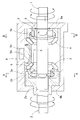
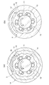
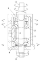
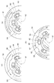
- Front sectional view of the rotation transmission device of the first embodiment a and b are sectional views taken along lines AA and BB in FIG. 1, respectively.
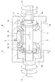
- Front sectional view of the rotation transmission device of the second embodiment a and b are sectional views taken along lines AA and BB in FIG. 3, respectively.
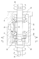
- Front sectional view of the rotation transmission device of the third embodiment a and b are sectional views taken along lines AA and BB in FIG. 5, respectively.
- Front sectional view of the rotation transmission device of the fourth embodiment a and b are sectional views taken along lines AA and BB in FIG. 7, respectively.
- Front sectional view of the rotation transmission device of the fifth embodiment a and b are sectional views taken along lines AA and BB in FIG. 9, respectively.
- Front sectional view of the rotation transmission device of the sixth embodiment a and b are sectional views taken along lines AA and BB in FIG. 11, respectively.
- Front sectional view of a conventional rotation transmission device a, b, and c are cross-sectional views taken along lines AA, BB, and CC, respectively, of FIG.
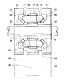
- Front sectional view of the rotation transmission device of the seventh embodiment a and b are explanatory views of the operation of the rotation transmission device of FIG.
- Front sectional view of the rotation transmission device of the eighth embodiment a and b are explanatory views of the operation of the rotation transmission device of FIG.
- the rotation transmission device includes input / output shafts 1 and 2 disposed on the same axis, and a pair of opposed bevel gears 3 and 4 that are rotatably fitted on the outer periphery of the input shaft 1.
- Intermediate bevel gear 5 meshing with both opposed bevel gears 3, 4, first one-way clutch 6 disposed between input shaft 1 and one (output side) opposed bevel gear 3, input shaft 1 and the other
- a second one-way clutch 7 disposed between the (input side) opposed bevel gears 4.
- the input shaft 1 and the output shaft 2 are rotatably supported by inner peripheral surfaces of through holes formed in both end lid portions 8a and 8b of the cylindrical casing 8, respectively. Further, the intermediate bevel gear 5 is rotatably fitted with a shaft portion 5a in a circular hole 8c formed in the inner peripheral surface of the casing 8.
- the casing 8 is divided into two parts so that the input / output shafts 1 and 2, the bevel gears 3, 4 and 5, and the one-way clutches 6 and 7 are integrated. It has become.
- the output shaft 2 is provided with two stages of a small-diameter cylindrical portion 2a rotatably supported by the casing lid portion 8b and a large-diameter cylindrical portion 2b to which the output-side counter bevel gear 3 is connected.
- the front end of the input shaft 1 is inserted into the cylindrical portions 2 a and 2 b of the output shaft 2 and is prevented from coming off by a retaining ring 9.
- Each of the opposed bevel gears 3 and 4 has cylindrical portions 3a and 4a for accommodating the one-way clutches 6 and 7, respectively.
- the opposed bevel gear 3 on the output side has a large cylindrical portion 3a of the output shaft 2. It is fitted in the inner periphery of the diameter cylinder portion 2b so as not to rotate, and rotates together with the output shaft 2.
- Each of the one-way clutches 6, 7 is provided with a plurality of inclined cam surfaces 11 on the inner peripheral surface of the outer ring 10, as shown in FIGS. 2 (a) and 2 (b). Rollers 12 as engaging elements are arranged at the directional positions, and each roller 12 is pressed by a spring 13 in a direction locked by the cam surface 11. Both the one-way clutches 6 and 7 have the same specifications, and in the first one-way clutch 6, each roller 12 is locked by the cam surface 11 when the outer ring 10 rotates in the reverse direction (right rotation in the figure). The second one-way clutch 7 is incorporated such that each roller 12 is locked by the cam surface 11 when the outer ring 10 rotates forward (left rotation in the figure).
- the first one-way clutch 6 transmits the rotation when the output-side counter bevel gear 3 that rotates integrally with the outer ring 10 rotates in the reverse direction or when the input shaft 1 rotates in the forward direction
- the second one-way clutch 6 The clutch 7 transmits rotation when the input-side counter bevel gear 4 that rotates integrally with the outer ring 10 rotates forward or when the input shaft 1 rotates reversely.
- the reverse rotation is transmitted to the input-side counter bevel gear 4 by the second one-way clutch 7. Then, the reverse rotation of the input-side counter bevel gear 4 is transmitted as a normal rotation to the output-side counter bevel gear 3 via the intermediate bevel gear 5, and the output shaft 2 rotates in the same direction as the bevel gear 3.
- the first one-way clutch 6 does not transmit rotation because the input shaft 1 rotates in the reverse direction and the output-side counter bevel gear 3 rotates in the forward direction at the same time.
- this rotation transmission device uses the two one-way clutches 6 and 7 so that the forward rotation is output to the output shaft 2 regardless of whether forward or reverse rotation is input to the input shaft 1. Therefore, compared with the above-mentioned conventional device (FIGS. 13 and 14) incorporating three one-way clutches, the number of parts is simple, and there is a problem due to misalignment of each clutch during rotation. It is difficult to obtain a stable rotation transmission operation. Further, in the above-described conventional device, one of the one-way clutches has a different specification (diameter dimension) from the other, whereas in this device, each of the one-way clutches 6 and 7 has the same specification. Therefore, it is easy to manage parts of the one-way clutch before assembly.
- the rotation transmission device of this embodiment incorporates two one-way clutches in the same direction with the input side and output side of the first embodiment reversed. That is, as shown in FIG. 3, the input shaft 14 of this embodiment has the same configuration as the output shaft 2 of the first embodiment, and the output shaft 15 has the same configuration as the input shaft 1 of the first embodiment.
- the first one-way clutch 16 disposed between one (input side) opposed bevel gear 3 and the output shaft 15, and the other (output side).
- the second one-way clutch 17 disposed between the counter bevel gear 4 and the output shaft 15 is incorporated so that the rollers 12 are locked by the cam surface 11 when the outer ring 10 rotates forward. Yes.
- the configuration of the other parts is the same as in the first embodiment.
- the reverse rotation of the bevel gear 3 is transmitted as a normal rotation to the output-side counter bevel gear 4 via the intermediate bevel gear 5.
- the forward rotation of the output-side counter bevel gear 4 is transmitted to the output shaft 15 by the second one-way clutch 17.
- the first one-way clutch 16 does not transmit the rotation because the opposed bevel gear 3 on the input side rotates reversely and the output shaft 15 rotates forward at the same time.
- this embodiment also employs two one-way clutches 16 and 17 to construct a mechanism that converts forward and reverse bi-directional rotations input to the input shaft 14 into forward rotations and outputs them to the output shaft 15. Therefore, it has the same features as the first embodiment.
- FIGS. 5 and 6A and 6B show the third embodiment
- FIGS. 7 and 8A and 8B show the fourth embodiment, respectively.
- the rotation transmission device of each of these embodiments enables rotation transmission between the pair of opposed bevel gears 3 and 4 of the first and second embodiments with an external rotation member (not shown).
- Ring gears 3b and 4b are provided as rotation transmission means, and these counter bevel gears 3 and 4 also serve as an output shaft or an input shaft.
- a cylindrical casing 18 having both ends opened is used, and an intermediate portion between the cylindrical shaft 19a through which the input shaft 1 of the third embodiment or the output shaft 15 of the fourth embodiment is passed.
- a support member 19 including a cylindrical portion 19b that is passed through the shaft hole of the bevel gear 20 is provided.
- the support member 19 is fixed by bringing a part of the cylindrical portion 19a into contact with the inner peripheral surface of the casing 18 and fitting the column portion 19b into a circular hole 18a formed in the inner peripheral surface of the casing 18,
- the input shaft 1 or the output shaft 15 is rotatably supported by the inner peripheral surface of the cylindrical portion 19a, and the intermediate bevel gear 20 is rotatably supported by the column portion 19b. Further, the input shaft 1 or the output shaft 15 supported by the support member 19 is prevented from coming off by two retaining rings 9.
- each counter bevel gears 3 and 4 transmit rotation with an external rotation member with the ring gears 3b and 4b provided in the site
- the output shaft 2 of the first embodiment (the input shaft 14 of the second embodiment) is unnecessary.
- the third embodiment is the same as the first embodiment
- the fourth embodiment is the same as the second embodiment. As a result, in the third and fourth embodiments, the entire apparatus is more compact in the axial direction than in the first and second embodiments.
- rotation transmission means between the external rotating members provided in each opposed bevel gear is not limited to the ring gear as in the embodiment, and a pulley or the like may be employed.
- the rotation transmission device of this embodiment has a pair of input / output shafts 21, 22 arranged on the same axis and a pair of fittings fitted on the outer periphery of the input shaft 21, as in the first embodiment.
- Opposite bevel gears 23, 24 and intermediate bevel gears 25 meshing with both counter bevel gears 23, 24 are provided, and each bevel gear 23, 24, 25 and two one-way clutches 26, 27 are provided in the cylindrical casing 8. Is housed inside.
- the configuration in which the input / output shafts 21 and 22 and the intermediate bevel gear 25 are rotatably supported by the casing 8 is the same as that of the first embodiment.
- the difference of this embodiment from the first embodiment is that the input shaft 21 and one (input side) counter bevel gear 23 are connected so as to rotate integrally, the input shaft 21 and the output shaft 22 A first one-way clutch 26 is disposed therebetween, and a second one-way clutch 27 having a larger radial dimension than the first one-way clutch 26 is provided between the other (output-side) counter bevel gear 24 and the output shaft 22. And that the one-way clutches 26 and 27 are assembled in the same direction.
- the output shaft 22 includes a small-diameter cylindrical portion 22a that is rotatably supported by the casing lid portion 8b and a large-diameter cylindrical portion 22b that accommodates the two one-way clutches 26 and 27 in two stages. Yes.
- the input-side counter bevel gear 23 rotates integrally with the input shaft 21 by key connection, and the output-side counter bevel gear 24 is inserted between the input shaft 21 and the second one-way clutch 27.
- a cylindrical portion 24a is inserted between the input shaft 21 and the second one-way clutch 27.
- each one-way clutch 26, 27 is assembled so that each roller 12 is locked by the cam surface 11 when the outer ring 10 rotates in the reverse direction, as shown in FIGS. 10 (a) and 10 (b). It is. That is, the first one-way clutch 26 transmits rotation when the input shaft 21 rotates forward, and the second one-way clutch 27 transmits rotation when the output-side counter bevel gear 24 rotates forward. It has become.
- the reverse rotation of the bevel gear 23 is transmitted as a normal rotation to the output-side counter bevel gear 24 via the intermediate bevel gear 25.
- the forward rotation of the output-side counter bevel gear 24 is transmitted to the output shaft 22 by the second one-way clutch 27.
- the first one-way clutch 26 does not transmit rotation because the input shaft 21 rotates in the reverse direction and the output shaft 22 rotates in the forward direction at the same time.
- FIG. 11 and FIG. 12 show a sixth embodiment.
- the rotation transmission device of this embodiment incorporates two one-way clutches in opposite directions with the input side and output side of the fifth embodiment reversed. That is, as shown in FIG. 11, the input shaft 28 of this embodiment has the same configuration as the output shaft 22 of the fifth embodiment, and the output shaft 29 has the same configuration as the input shaft 21 of the fifth embodiment.
- the first one-way clutch 30 disposed between the input shaft 28 and the output shaft 29 is configured so that each roller 12 is rotated when the outer ring 10 rotates forward.
- the second one-way clutch 31 that is incorporated so as to be locked by the cam surface 11 and disposed between the input shaft 28 and the other (input side) counter bevel gear 24 is configured so that each of the outer rings 10 rotates in the reverse direction.
- the roller 12 is incorporated so as to be locked by the cam surface 11.
- the structure of other parts is the same as that of the fifth embodiment.
- the forward rotation is transmitted to the output shaft 29 by the first one-way clutch 30.
- the forward rotation of the output-side counter bevel gear 23 that rotates integrally with the output shaft 29 is transmitted as a reverse rotation to the input-side counter bevel gear 24 via the intermediate bevel gear 25, but the second one-way clutch 31 does not transmit rotation.
- the reverse rotation is transmitted to the counter bevel gear 24 on the input side by the second one-way clutch 31.
- the reverse rotation of the input-side counter bevel gear 24 is transmitted as a normal rotation to the output-side counter bevel gear 23 via the intermediate bevel gear 25, and the output shaft 29 rotates positively integrally with the bevel gear 23.
- the first one-way clutch 30 does not transmit rotation because the input shaft 28 rotates reversely and the output shaft 29 rotates forward at the same time.
- the forward and reverse bi-directional rotations input to the input shaft are converted into forward rotations using two one-way clutches.
- a mechanism for outputting to the output shaft can be constructed.
- the one-way clutch having a roller as an engagement element is used, but other types of one-way clutches having a sprag or the like as an engagement element can also be used.
- FIG. 15 and 16 show a seventh embodiment.
- This rotation transmission device is incorporated in an office machine such as a copying machine or a printer.
- the fixed shaft 32, a first input member 33, a second input member 34, and an output arranged around the fixed shaft 32 are provided. It is basically composed of the member 35.
- the members 33, 34, and 35 arranged around the fixed shaft 32 are prevented from coming off by retaining rings 36 that are fitted to both ends of the fixed shaft 32.
- the second input member 34 has a boss portion 37 that is rotatably fitted on the outer periphery of the fixed shaft 32, and an intermediate shaft 38 that extends in a direction perpendicular to the fixed shaft 32 at the center in the longitudinal direction of the boss portion 37.
- the first input member 33 and the output member 35 are rotatably attached to the outer periphery of the boss portion 37 with the intermediate shaft 38 interposed therebetween.
- the first input member 33 and the output member 35 are provided with bevel gears 39 and 40 on opposite surfaces of each other.
- the intermediate bevel gear 41 that meshes with the bevel gears 39 and 40 of the first input member 33 and the output member 35 is rotatably attached to the second input member 34 at a position sandwiching the fixed shaft 32 around the intermediate shaft 38. It has been.
- Each intermediate bevel gear 41 of the second input member 34 is fitted into a small diameter portion formed near both ends of the intermediate shaft 38, and a retaining ring 42 fitted into the large diameter portion of the intermediate shaft 38 and both ends of the intermediate shaft 38. It is positioned between.
- first input member 33 and the output member 35 are provided with ring gears 43 and 44 coaxial with the fixed shaft 32 on the outer peripheral portions thereof.
- the second input member 34 has ring gears 45 coaxial with the fixed shaft 32 attached to both ends of the intermediate shaft 38.
- the first drive gear 46 is connected to the ring gear 43 of the first input member 33
- the second drive gear 47 is connected to the ring gear 45 of the second input member 34
- the driven gear 48 is connected to the ring gear 44 of the output member 35. It comes to mesh.
- a drive source for the first input member 33 is connected to the first drive gear 46
- a drive source for the second input member 34 is connected to the second drive gear 47 (not shown).
- the paper feed roller rotates in the opposite direction to the state of a) (the same direction as the first input member 33), and the paper feed roller is rotated in reverse via the driven gear 48. If the revolution speed of the intermediate bevel gear 41 is further increased, the rotation of the intermediate bevel gear 41 stops when the rotational speed of the first input member 33 becomes equal to the rotational speed of the first input member 33. If the upper limit is exceeded, the intermediate bevel gear 41 rotates in the direction opposite to the state shown in FIG. At this time, the rotation direction of the output member 35 remains opposite to that shown in FIG.
- the revolution speed of the intermediate bevel gear 41 of the second input member 34 is changed to about 1/2 of the rotation speed of the first input member 33 in a state where the first input member 33 is rotated. By doing so, the rotation direction of the output member 35 can be reversed.
- This rotation transmission device has the above-described configuration and operation, and does not use a spring clutch to reverse the rotation direction of the output member 35. Therefore, the rotation transmission device has a simple structure and a stable reversing operation compared to the conventional one. can get.
- FIG. 17 and 18 show an eighth embodiment.
- the second input member 34 of the seventh embodiment is used as the first input member 49
- the ring gear 45 is meshed with the first drive gear 46
- the second input member The first input member 33 of the seventh embodiment is used as 50
- the ring gear 43 is meshed with the second drive gear 47.
- the structure of other parts is the same as that of the seventh embodiment.
- this rotation transmission device is as follows. First, as shown in FIG. 18A, when the second input member 50 is stopped and a drive torque is input to the first input member 49 via the first drive gear 46 (the rotation direction is opposite to that of the seventh embodiment). Direction), the intermediate bevel gear 41 rotates and revolves along with the rotation of the intermediate shaft 38, whereby the output member 35 rotates in the same direction as the first input member 49, and the paper feed roller via the driven gear 48. (Not shown) is rotated forward.
- the structure is simpler and a stable reversing operation can be obtained as compared with the conventional one using a spring clutch.
Landscapes
- Engineering & Computer Science (AREA)
- General Engineering & Computer Science (AREA)
- Mechanical Engineering (AREA)
- Structure Of Transmissions (AREA)
- Gear Transmission (AREA)
Abstract
Description
2、15、22、29 出力軸
3、4、23、24 対向傘歯車
3b、4b リング歯車
5、20、25 中間傘歯車
6、16、26、30 第1の一方向クラッチ
7、17、27、31 第2の一方向クラッチ
8、18 ケーシング
10 外輪
11 カム面
12 ころ
13 ばね
19 支持部材
32 固定軸
33、49 第1入力部材
34、50 第2入力部材
35 出力部材
37 ボス部
38 中間軸
39、40 傘歯車
41 中間傘歯車
43、44、45 リング歯車
46 第1駆動歯車
47 第2駆動歯車
48 被駆動歯車
Claims (5)
- 入力軸と出力軸を同一軸心上に配し、前記入力軸に入力される正逆両方向回転を一方向回転に変換して前記出力軸に出力する回転伝達装置において、前記入出力軸と同一軸心上に一対の対向傘歯車を配して、これらの両対向傘歯車と噛み合う中間傘歯車を設けるとともに、前記出力軸と一方の対向傘歯車とを一体回転するように接続し、前記入力軸の正回転を前記出力軸または一方の対向傘歯車に伝達する第1の一方向クラッチと、前記入力軸の逆回転を他方の対向傘歯車に伝達する第2の一方向クラッチを設けたことを特徴とする回転伝達装置。
- 入力軸と出力軸を同一軸心上に配し、前記入力軸に入力される正逆両方向回転を一方向回転に変換して前記出力軸に出力する回転伝達装置において、前記入出力軸と同一軸心上に一対の対向傘歯車を配して、これらの両対向傘歯車と噛み合う中間傘歯車を設けるとともに、前記入力軸と一方の対向傘歯車とを一体回転するように接続し、前記入力軸または一方の対向傘歯車の正回転を前記出力軸に伝達する第1の一方向クラッチと、前記他方の対向傘歯車の正回転を前記出力軸に伝達する第2の一方向クラッチを設けたことを特徴とする回転伝達装置。
- 前記第1の一方向クラッチと前記第2の一方向クラッチを同一仕様のものとしたことを特徴とする請求項1または2に記載の回転伝達装置。
- 前記一対の対向傘歯車の少なくとも一方に、外部の回転部材との間での回転伝達を可能とする回転伝達手段を設けたことを特徴とする請求項1乃至3のいずれかに記載の回転伝達装置。
- 前記回転伝達手段がリング歯車であることを特徴とする請求項4に記載の回転伝達装置。
Priority Applications (2)
| Application Number | Priority Date | Filing Date | Title |
|---|---|---|---|
| CN2010800078491A CN102317647A (zh) | 2009-03-16 | 2010-03-10 | 旋转传动装置 |
| US13/145,372 US9086103B2 (en) | 2009-03-16 | 2010-03-10 | Rotation transmission device |
Applications Claiming Priority (4)
| Application Number | Priority Date | Filing Date | Title |
|---|---|---|---|
| JP2009062520A JP5517146B2 (ja) | 2009-03-16 | 2009-03-16 | 一方向回転伝達装置 |
| JP2009-062520 | 2009-03-16 | ||
| JP2009-165485 | 2009-07-14 | ||
| JP2009165485A JP2011021640A (ja) | 2009-07-14 | 2009-07-14 | 回転方向反転ユニット |
Publications (1)
| Publication Number | Publication Date |
|---|---|
| WO2010106952A1 true WO2010106952A1 (ja) | 2010-09-23 |
Family
ID=42739612
Family Applications (1)
| Application Number | Title | Priority Date | Filing Date |
|---|---|---|---|
| PCT/JP2010/054013 Ceased WO2010106952A1 (ja) | 2009-03-16 | 2010-03-10 | 回転伝達装置 |
Country Status (3)
| Country | Link |
|---|---|
| US (1) | US9086103B2 (ja) |
| CN (1) | CN102317647A (ja) |
| WO (1) | WO2010106952A1 (ja) |
Cited By (6)
| Publication number | Priority date | Publication date | Assignee | Title |
|---|---|---|---|---|
| CN102352914A (zh) * | 2011-09-28 | 2012-02-15 | 涂鹏远 | 一种脉冲间歇式传动机构 |
| CN102732692A (zh) * | 2012-06-20 | 2012-10-17 | 无锡宇吉科技有限公司 | 炉门电动车轮组件 |
| CN103016689A (zh) * | 2012-12-06 | 2013-04-03 | 浙江乐客来机械有限公司 | 一种齿轮箱 |
| WO2013102319A1 (zh) * | 2012-01-05 | 2013-07-11 | 天信仪表集团有限公司 | 一种双向计数器 |
| EA021561B1 (ru) * | 2012-03-28 | 2015-07-30 | Михаил Михайлович Украинко | Механизм для преобразования возвратно-вращательного движения в одностороннее вращательное |
| EA023672B1 (ru) * | 2012-03-28 | 2016-06-30 | Михаил Михайлович Украинко | Механизм для преобразования возвратно-вращательного движения в одностороннее вращательное |
Families Citing this family (17)
| Publication number | Priority date | Publication date | Assignee | Title |
|---|---|---|---|---|
| JP5567517B2 (ja) * | 2011-03-22 | 2014-08-06 | 株式会社デンソー | 動力伝達装置 |
| US9572616B2 (en) * | 2013-09-04 | 2017-02-21 | Bradshaw Medical, Inc. | Continuous ratchet medical instrument drive |
| DE102015203922A1 (de) * | 2015-03-05 | 2016-09-08 | Schaeffler Technologies AG & Co. KG | Freilaufeinrichtung für ein Automatikgetriebe |
| CN105094162B (zh) * | 2015-08-14 | 2018-02-13 | 金陵科技学院 | 一种变速巡航自动旋转餐桌及其控制方法 |
| US10337487B2 (en) * | 2016-05-17 | 2019-07-02 | Sairandri SATHYANARAYANAN | Multi axial translational and rotational motion to unidirectional rotational motion |
| CN106988869B (zh) * | 2017-04-27 | 2022-12-09 | 吴坤柳 | 直线/旋转转换机构及发动机 |
| US10920739B2 (en) * | 2018-04-16 | 2021-02-16 | Moosa Nematollahi Saein | Wave-power system |
| CN110386047B (zh) * | 2019-08-20 | 2024-05-17 | 宁波帅特龙集团有限公司 | 自动折叠伸缩式车用杯托 |
| CN111632955B (zh) * | 2020-05-27 | 2022-03-04 | 黄河水利职业技术学院 | 一种基于棘轮传动原理的内存条清理装置 |
| CN112516518A (zh) * | 2020-11-16 | 2021-03-19 | 王进 | 一种可计数的安全的卧推杠铃 |
| CN115899186A (zh) * | 2021-08-10 | 2023-04-04 | 青岛海尔洗衣机有限公司 | 一种换向传动机构及干衣设备 |
| CN113700801B (zh) * | 2021-09-22 | 2024-01-26 | 郭宁波 | 一种自锁减速机 |
| CN114321405A (zh) * | 2022-01-26 | 2022-04-12 | 石志生 | 一种气动蝶阀 |
| CN114623204A (zh) * | 2022-03-21 | 2022-06-14 | 哈尔滨理工大学 | 一种同轴式多输出减速器 |
| CN115076246A (zh) * | 2022-06-28 | 2022-09-20 | 陕西航空电气有限责任公司 | 一种可隔离轴向振动的轴联接器 |
| CN115741330B (zh) * | 2022-12-20 | 2024-01-16 | 中山市金马事厨房用品实业有限公司 | 一种不锈钢设备生产用打磨装置 |
| CN118481988B (zh) * | 2024-07-15 | 2025-07-18 | 山东派金真空科技有限公司 | 一种真空玻璃炉用多缸体抽真空泵 |
Citations (4)
| Publication number | Priority date | Publication date | Assignee | Title |
|---|---|---|---|---|
| JPS57100649U (ja) * | 1980-12-12 | 1982-06-21 | ||
| JPH064455U (ja) * | 1992-06-24 | 1994-01-21 | 信一 七野 | 一段同軸ワンウェイ出力機構 |
| JP2004084783A (ja) * | 2002-08-27 | 2004-03-18 | Ntn Corp | 回転方向変換装置 |
| JP2008240786A (ja) * | 2007-03-26 | 2008-10-09 | Ntn Corp | 傘歯車機構を用いた駆動力制御装置 |
Family Cites Families (10)
| Publication number | Priority date | Publication date | Assignee | Title |
|---|---|---|---|---|
| US832077A (en) * | 1905-05-06 | 1906-10-02 | R H Briggs Sr | Gearing for power-drills. |
| JPS57100649A (en) | 1980-12-12 | 1982-06-22 | Mitsubishi Electric Corp | Controller for running speed of magnetic tape |
| JPH064455A (ja) * | 1992-06-18 | 1994-01-14 | Hitachi Ltd | Dma転送方式 |
| JPH068301A (ja) | 1992-06-24 | 1994-01-18 | Fuji Kiki Kogyo Kk | 樹脂被覆管の製造方法 |
| US5860321A (en) * | 1995-03-15 | 1999-01-19 | Williams; Eugene A. | Power transmission utilizing conversion of inertial forces |
| US5881609A (en) * | 1996-10-16 | 1999-03-16 | Palmer; Leon Robert | Reversing-input bidirectional-output longitudinally-slideable-shaft |
| US5931062A (en) * | 1997-05-13 | 1999-08-03 | Marcovici; Mitch | Efficient mechanical rectifier |
| JP3915399B2 (ja) | 2000-11-20 | 2007-05-16 | 富士ゼロックス株式会社 | 画像形成装置 |
| JP2002168309A (ja) | 2000-12-01 | 2002-06-14 | Anelva Corp | 回転伝達機構 |
| JP2009008247A (ja) | 2007-02-28 | 2009-01-15 | Ntn Corp | 回転方向切替クラッチユニット |
-
2010
- 2010-03-10 WO PCT/JP2010/054013 patent/WO2010106952A1/ja not_active Ceased
- 2010-03-10 US US13/145,372 patent/US9086103B2/en not_active Expired - Fee Related
- 2010-03-10 CN CN2010800078491A patent/CN102317647A/zh active Pending
Patent Citations (4)
| Publication number | Priority date | Publication date | Assignee | Title |
|---|---|---|---|---|
| JPS57100649U (ja) * | 1980-12-12 | 1982-06-21 | ||
| JPH064455U (ja) * | 1992-06-24 | 1994-01-21 | 信一 七野 | 一段同軸ワンウェイ出力機構 |
| JP2004084783A (ja) * | 2002-08-27 | 2004-03-18 | Ntn Corp | 回転方向変換装置 |
| JP2008240786A (ja) * | 2007-03-26 | 2008-10-09 | Ntn Corp | 傘歯車機構を用いた駆動力制御装置 |
Cited By (6)
| Publication number | Priority date | Publication date | Assignee | Title |
|---|---|---|---|---|
| CN102352914A (zh) * | 2011-09-28 | 2012-02-15 | 涂鹏远 | 一种脉冲间歇式传动机构 |
| WO2013102319A1 (zh) * | 2012-01-05 | 2013-07-11 | 天信仪表集团有限公司 | 一种双向计数器 |
| EA021561B1 (ru) * | 2012-03-28 | 2015-07-30 | Михаил Михайлович Украинко | Механизм для преобразования возвратно-вращательного движения в одностороннее вращательное |
| EA023672B1 (ru) * | 2012-03-28 | 2016-06-30 | Михаил Михайлович Украинко | Механизм для преобразования возвратно-вращательного движения в одностороннее вращательное |
| CN102732692A (zh) * | 2012-06-20 | 2012-10-17 | 无锡宇吉科技有限公司 | 炉门电动车轮组件 |
| CN103016689A (zh) * | 2012-12-06 | 2013-04-03 | 浙江乐客来机械有限公司 | 一种齿轮箱 |
Also Published As
| Publication number | Publication date |
|---|---|
| CN102317647A (zh) | 2012-01-11 |
| US9086103B2 (en) | 2015-07-21 |
| US20110271795A1 (en) | 2011-11-10 |
Similar Documents
| Publication | Publication Date | Title |
|---|---|---|
| WO2010106952A1 (ja) | 回転伝達装置 | |
| JP5517146B2 (ja) | 一方向回転伝達装置 | |
| CN102884335B (zh) | 单向离合器 | |
| JP6277589B2 (ja) | 駆動伝達装置およびその駆動伝達装置を備えた画像形成装置 | |
| JP2008240786A (ja) | 傘歯車機構を用いた駆動力制御装置 | |
| JP5023030B2 (ja) | 摩擦クラッチの締結機構および該機構を備えるディファレンシャル装置 | |
| CN104956123B (zh) | 变速装置 | |
| JP2010223298A (ja) | 電動モータ駆動装置 | |
| KR100392697B1 (ko) | 변속기능이 있는 축이음구조 | |
| US8201479B2 (en) | Drive conversion mechanism enabling constantly meshed gears in a drive input gear train | |
| JP2011021640A (ja) | 回転方向反転ユニット | |
| JP2010276155A (ja) | 逆入力遮断ユニットおよびそれを用いた紙送り装置 | |
| EP0336239B1 (en) | Clutch mechanism in gear transmission | |
| JP5062122B2 (ja) | 車両の駆動装置 | |
| US20140027233A1 (en) | Freewheel device with switchable freewheel | |
| JP6918035B2 (ja) | フリータイプ双方向クラッチ | |
| JP7573943B2 (ja) | ラチェット型クラッチ | |
| JP2014062590A (ja) | 減速機 | |
| JP2013199999A (ja) | 減速機 | |
| JP5563492B2 (ja) | 一方向回転伝達装置 | |
| JP6034331B2 (ja) | 一方向への回転方向変換装置 | |
| JP2007028883A (ja) | ギヤドモータ及びギヤドモータ用軸部材 | |
| JP5934503B2 (ja) | チュービングポンプ装置 | |
| WO2010084811A1 (ja) | トルクリミッタ | |
| JP2008008450A (ja) | 駆動力伝達制御装置 |
Legal Events
| Date | Code | Title | Description |
|---|---|---|---|
| WWE | Wipo information: entry into national phase |
Ref document number: 201080007849.1 Country of ref document: CN |
|
| 121 | Ep: the epo has been informed by wipo that ep was designated in this application |
Ref document number: 10753444 Country of ref document: EP Kind code of ref document: A1 |
|
| WWE | Wipo information: entry into national phase |
Ref document number: 13145372 Country of ref document: US |
|
| NENP | Non-entry into the national phase |
Ref country code: DE |
|
| 122 | Ep: pct application non-entry in european phase |
Ref document number: 10753444 Country of ref document: EP Kind code of ref document: A1 |