WO2010106892A1 - 摩擦撹拌接合装置及び方法 - Google Patents
摩擦撹拌接合装置及び方法 Download PDFInfo
- Publication number
- WO2010106892A1 WO2010106892A1 PCT/JP2010/053109 JP2010053109W WO2010106892A1 WO 2010106892 A1 WO2010106892 A1 WO 2010106892A1 JP 2010053109 W JP2010053109 W JP 2010053109W WO 2010106892 A1 WO2010106892 A1 WO 2010106892A1
- Authority
- WO
- WIPO (PCT)
- Prior art keywords
- joining
- tool
- friction stir
- stir welding
- head
- Prior art date
- Legal status (The legal status is an assumption and is not a legal conclusion. Google has not performed a legal analysis and makes no representation as to the accuracy of the status listed.)
- Ceased
Links
Images




Classifications
-
- B—PERFORMING OPERATIONS; TRANSPORTING
- B23—MACHINE TOOLS; METAL-WORKING NOT OTHERWISE PROVIDED FOR
- B23K—SOLDERING OR UNSOLDERING; WELDING; CLADDING OR PLATING BY SOLDERING OR WELDING; CUTTING BY APPLYING HEAT LOCALLY, e.g. FLAME CUTTING; WORKING BY LASER BEAM
- B23K20/00—Non-electric welding by applying impact or other pressure, with or without the application of heat, e.g. cladding or plating
- B23K20/12—Non-electric welding by applying impact or other pressure, with or without the application of heat, e.g. cladding or plating the heat being generated by friction; Friction welding
-
- B—PERFORMING OPERATIONS; TRANSPORTING
- B23—MACHINE TOOLS; METAL-WORKING NOT OTHERWISE PROVIDED FOR
- B23K—SOLDERING OR UNSOLDERING; WELDING; CLADDING OR PLATING BY SOLDERING OR WELDING; CUTTING BY APPLYING HEAT LOCALLY, e.g. FLAME CUTTING; WORKING BY LASER BEAM
- B23K20/00—Non-electric welding by applying impact or other pressure, with or without the application of heat, e.g. cladding or plating
- B23K20/12—Non-electric welding by applying impact or other pressure, with or without the application of heat, e.g. cladding or plating the heat being generated by friction; Friction welding
- B23K20/122—Non-electric welding by applying impact or other pressure, with or without the application of heat, e.g. cladding or plating the heat being generated by friction; Friction welding using a non-consumable tool, e.g. friction stir welding
- B23K20/1245—Non-electric welding by applying impact or other pressure, with or without the application of heat, e.g. cladding or plating the heat being generated by friction; Friction welding using a non-consumable tool, e.g. friction stir welding characterised by the apparatus
-
- B—PERFORMING OPERATIONS; TRANSPORTING
- B23—MACHINE TOOLS; METAL-WORKING NOT OTHERWISE PROVIDED FOR
- B23K—SOLDERING OR UNSOLDERING; WELDING; CLADDING OR PLATING BY SOLDERING OR WELDING; CUTTING BY APPLYING HEAT LOCALLY, e.g. FLAME CUTTING; WORKING BY LASER BEAM
- B23K20/00—Non-electric welding by applying impact or other pressure, with or without the application of heat, e.g. cladding or plating
- B23K20/12—Non-electric welding by applying impact or other pressure, with or without the application of heat, e.g. cladding or plating the heat being generated by friction; Friction welding
- B23K20/122—Non-electric welding by applying impact or other pressure, with or without the application of heat, e.g. cladding or plating the heat being generated by friction; Friction welding using a non-consumable tool, e.g. friction stir welding
- B23K20/123—Controlling or monitoring the welding process
-
- B—PERFORMING OPERATIONS; TRANSPORTING
- B23—MACHINE TOOLS; METAL-WORKING NOT OTHERWISE PROVIDED FOR
- B23K—SOLDERING OR UNSOLDERING; WELDING; CLADDING OR PLATING BY SOLDERING OR WELDING; CUTTING BY APPLYING HEAT LOCALLY, e.g. FLAME CUTTING; WORKING BY LASER BEAM
- B23K20/00—Non-electric welding by applying impact or other pressure, with or without the application of heat, e.g. cladding or plating
- B23K20/12—Non-electric welding by applying impact or other pressure, with or without the application of heat, e.g. cladding or plating the heat being generated by friction; Friction welding
- B23K20/122—Non-electric welding by applying impact or other pressure, with or without the application of heat, e.g. cladding or plating the heat being generated by friction; Friction welding using a non-consumable tool, e.g. friction stir welding
- B23K20/1245—Non-electric welding by applying impact or other pressure, with or without the application of heat, e.g. cladding or plating the heat being generated by friction; Friction welding using a non-consumable tool, e.g. friction stir welding characterised by the apparatus
- B23K20/125—Rotary tool drive mechanism
Definitions
- the present invention relates to a friction stir welding apparatus and method, and more particularly, to a friction stir welding apparatus and method for joining by rotating a joining tool against a member to be joined to cause plastic flow.
- friction stir welding apparatuses are used in a wide range of fields such as railway vehicles, ships, aircraft, bridges, and the like.
- Patent Document 1 As a typical conventional friction stir welding apparatus, while rotating a welding tool, it is pressed against one surface of a member to be joined, thereby generating a plastic flow at the joining site, and a material mixed by plastic flow is obtained.
- Patent Document 1 There is an apparatus for joining both members by solidifying (Patent Document 1).
- Patent Document 1 a pressure type air cylinder is used as means for achieving the pressing force of the welding tool.
- FIG. 8 shows a schematic configuration of this type of friction stir welding apparatus.
- This apparatus 100 is connected to a head support portion 101 of the apparatus main body through a linear guide 102 so as to be freely movable in the vertical direction.
- the welding tool 104 is rotated by a tool rotation drive motor 105 provided on the welding head 103. Driven by rotation.
- An air cylinder 106 for driving the head is fixed to the head support portion 101, and a joining head 103 is attached to a piston rod 106A of the air cylinder 106.
- Compressed air is supplied from the compressed air source 120 to the pressurizing chamber 107 of the air cylinder 106 via the pressurizing side pipe 109.
- a back pressure side pipe 121 is connected to the back pressure chamber 108 of the air cylinder 106.
- a pressure control valve 122 and an electromagnetic valve 123 are provided in the middle of the pressurizing side pipe 109.
- a back pressure side pipe 121 is also connected to the electromagnetic valve 123. By switching the electromagnetic valve 123, the back pressure chamber 108 of the air cylinder 106 can be released to the atmosphere.
- the pressure control valve 122 and the electromagnetic valve 123 are controlled by the control device 124.
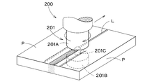
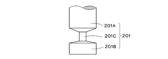
- the bobbin tool type friction stir welding apparatus 200 includes a pair of upper and lower rotating bodies 201 ⁇ / b> A and 201 ⁇ / b> B arranged at fixed intervals so as to sandwich both front and back surfaces of the member P to be joined.
- a joining tool 201 including a stirring shaft 201C provided between the upper and lower rotating bodies 201A and 201B is provided.
- the joining tool 201 When joining the abutting portions between the members to be joined P using this bobbin tool type apparatus, the joining tool 201 is moved along the abutting line L between the members to be joined P while rotating the joining tool 201. Then, frictional heat is generated on both the front and back surfaces and the butted surface of the member P to be joined, and plastic flow occurs. After passing through the welding tool 201, the butted portions of the two bonded members P that are mixed with each other by plastic flow are solidified, whereby the two bonded members P are bonded to each other.
- this fixed bobbin tool type friction stir welding apparatus 200 a backing metal is not required, so that the structure of the apparatus is simplified, and the constraint conditions of the members to be joined are relaxed. Further, by causing plastic flow on both the front and back surfaces of the member to be bonded P, there is also an advantage that a bonding failure on the back surface side of the member to be bonded P can be reliably prevented.
- the above-described bobbin tool type apparatus uses a fixed bobbin tool in which the distance between the upper and lower rotating bodies of the joining tool is fixed, and moves the fixed bobbin tool along the butt line of the members to be joined. However, it does not have a function of causing the position of the bobbin tool in the vertical direction to follow the surface (upper surface / lower surface) of the member to be bonded during bonding. That is, the joining by the fixed bobbin tool is performed by a position control operation based on a previously taught path.
- Patent Documents 3 and 4 a friction stir welding apparatus using a self-reacting bobbin tool capable of changing the interval between the upper and lower rotating bodies.
- the clamping force between the upper rotating body (upper shoulder) and the lower rotating body (lower shoulder) is controlled by a force control method using hydraulic pressure, and the upper rotating body and the lower rotating body.
- Each of the bodies can be made to follow the surface (upper surface / lower surface) of the member to be joined.
- the axis configuration of the joining head is a total of three axes including two pressing shafts of the upper and lower rotating bodies (shoulders) and one tool rotating shaft. There is a problem that it is complicated and expensive.
- the vertical positional relationship between the bobbin tool and the member to be joined has changed due to the dimensional error or attachment error of the member to be joined while using the fixed bobbin tool. Even in such cases, it is required to appropriately respond to such changes.
- the above-described bobbin tool type friction stir welding apparatus may not be able to properly join. Even in such a case, the one-side pressing type friction stir welding apparatus 100 that presses the welding tool 104 only on one side of the member P to be joined as shown in FIGS. is there.
- a single friction stir welding apparatus can appropriately replace the conventional one-side pressing type bonding and the bobbin tool type bonding by appropriately replacing the welding tools.
- the fixed bobbin tool type friction stir welding apparatus does not have means for generating a large pressing force like the air cylinder in the single side pressing type friction stir welding apparatus. It is not possible to achieve appropriate joining conditions simply by replacing the one with a single-side pressing type joining tool.
- the conventional friction stir welding apparatus described above is configured so that the welding tool is pressed against the member to be joined by a pressing air cylinder, the pressing force applied to the member to be joined is applied by the air cylinder. The pressure and the downward force due to the weight of the joining head including the joining tool are combined.
- Japanese Patent No. 3261431 Japanese Patent No. 2712838 JP 2008-149331 A Japanese Patent No. 4175484
- the present invention has been made in consideration of the above-described circumstances, and provides a friction stir welding apparatus and method capable of performing good friction stir welding on various members to be joined having different materials and shapes.
- the purpose is to provide.
- a friction stir welding apparatus includes a joining tool that includes a joining tool that is in contact with a member to be joined and a rotational drive unit that rotationally drives the joining tool, and a displacement drive for the joining head
- a head driving means including a fluid pressure cylinder having the joining head attached to a piston rod of the head driving means, and a first pressurization for supplying a pressurized fluid to the first compartment of the fluid pressure cylinder.
- a control means for controlling the pressure of each pressurized fluid supplied simultaneously to the two compartments.
- the joining tool is a fixed bobbin tool having a pair of rotating bodies arranged at a fixed interval and a stirring shaft provided between the pair of rotating bodies.
- the joining tool is configured to abut only on one side of the member to be joined.
- control means has a pressure difference between the pressurized fluid supplied from the first pressurizing means and a pressure of the pressurized fluid supplied from the second pressurizing means.
- Each pressure is controlled to support at least a portion of the weight.
- the first pressurizing means and the second pressurizing means are provided with a common pressurized fluid source.
- the apparatus further includes a tool position correction mechanism that displaces the welding tool following the surface shape of the member to be bonded, and the tool position correction mechanism includes a contact member that contacts the surface of the member to be bonded. And elastic support means for elastically supporting the contact member with respect to the joining head.
- the elastic support means includes a compression spring or a fluid pressure cylinder.
- the apparatus further includes a head holding mechanism that urges the bonding head in a direction away from the member to be bonded to hold the bonding head in a predetermined position.
- the head holding mechanism has a fluid pressure cylinder including a piston rod abutted against the joining head.
- control means includes any one of the first compartment and the second compartment from a control mode in which the pressurized fluids are simultaneously supplied to the first compartment and the second compartment. It further has a function of switching to an additional control mode for supplying the pressurized fluid to only one of them.
- the additional control mode is a mode in which the joining tool configured to be in contact with only one surface of the member to be joined is pressed against the member to be joined.
- the additional control mode is a mode in which at least a part of the weight of the joining head is supported by the pressure of the pressurized fluid.
- the present invention provides a friction stir welding method in which a rotating welding tool is joined by abutting against a member to be joined to cause plastic flow, and the joining head including the joining tool has its piston rod.
- a pressure control step of controlling the pressure of each pressurized fluid supplied simultaneously to the first compartment and the second compartment of the fluid pressure cylinder attached to the fluid pressure cylinder, and the pressure of each pressurized fluid by the pressure control step
- a tool transfer step of moving the joining tool along a joining line of the members to be joined.
- a fixed bobbin tool having a pair of rotating bodies arranged at fixed intervals and a stirring shaft provided between the pair of rotating bodies is used.
- a joining tool configured to be brought into contact with only one surface of the member to be joined is used.
- the pressure of the pressurizing fluid supplied to the first compartment of the fluid pressure cylinder and the pressure of the pressurized fluid supplied to the second compartment are determined by the pressure difference of the joining head.
- the joining tool is displaced following the surface shape of the member to be joined.
- the joining head is urged toward the direction away from the member to be joined to hold the joining head in a predetermined position.
- the holding of the joining head in the predetermined position is released.
- the joining tool can simultaneously supply pressurized fluid to both compartments of a hydraulic cylinder attached to its piston rod, and the pressure of each pressurized fluid supplied to both compartments. Therefore, good friction stir welding can be performed on various members to be joined having different materials and shapes.
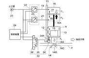
- FIG. 1 The figure which showed schematic structure of the friction stir welding apparatus by one Embodiment of this invention. It is the modification of embodiment shown in FIG. 1, Comprising: The figure which showed schematic structure of the friction stir welding apparatus provided with the single-sided press-type joining tool. It is the other modification of embodiment shown in FIG. 1, Comprising: The figure which showed schematic structure of the friction stir welding apparatus provided with the tool position correction mechanism which has a compression spring. It is the other modification of embodiment shown in FIG. 1, Comprising: The figure which showed schematic structure of the friction stir welding apparatus provided with the tool position correction mechanism which has an air cylinder. It is the other modification of embodiment shown in FIG.
- FIG. 6 is a diagram showing a schematic configuration of a friction stir welding apparatus including a head holding mechanism, which is another modification of the embodiment shown in FIG. 1.
- FIG. 6 is a diagram showing a schematic configuration of a friction stir welding apparatus including another tool position correction mechanism and a head holding mechanism, which is another modification of the embodiment shown in FIG. 1.
- the friction stir welding apparatus 10 includes a joining head 13 that is mounted on a head support 11 of the apparatus main body via a linear guide 12 so as to be linearly movable in the vertical direction.
- a joining tool 14 that is in contact with the member P to be joined at the time of joining work is rotatably mounted on the joining head 13.
- the joining tool 14 is a tool rotation drive motor (rotation drive) provided on the joining head 13.
- Means) 15 is rotationally driven.
- An air cylinder (head driving means) 16 for driving the head is fixed to the head support portion 11, and a joining head 13 is attached to a piston rod 16 A of the air cylinder 16.
- another fluid pressure cylinder such as a hydraulic cylinder may be provided.
- Compressed air is supplied to the first compartment 17 of the air cylinder 16 from a compressed air source (pressurized fluid source) 20 via a first pipe 19.
- a compressed air source pressurized fluid source
- the compressed air is similarly supplied from the compressed air source 20 to the second compartment 18 of the air cylinder 16 via the second pipe 21.
- the first piping 19 and the compressed air source 20 constitute a first pressurizing means that pressurizes the first compartment 17, and the second piping 21 and the compressed air source 20 pressurize the second compartment 18.
- a pressure means is configured.
- a first pressure control valve 22 is provided in the middle of the first pipe 19, and a second pressure control valve 23 is provided in the middle of the second pipe 21.
- the pressure setting values of the first pressure control valve 22 and the second pressure control valve 23 are adjusted by the control device 24.
- the joining tool 14 in the present embodiment is a fixed bobbin tool, and includes an upper rotating body 14A and a lower rotating body 14B that are spaced apart at fixed intervals so as to come into contact with the upper and lower surfaces of the member P to be joined during the joining operation.
- the stirring shaft 14C is provided between the rotating bodies 14A and 14B, and is inserted into the butted portion between the members P to be joined.
- the interval between the upper and lower rotating bodies 14A and 14B is fixedly set in consideration of the thickness of the member to be bonded P, and the upper rotating body 14A is in contact with the upper surface of the member to be bonded P and the lower rotation is performed.
- the body 14B is set so as to contact the lower surface of the member P to be joined.
- the tool rotation drive motor 15 rotates the welding tool 14 while the upper and lower rotary bodies 14A and 14B are covered.
- the stirring shaft 14C of the welding tool 14 is moved along the butting line so as to sandwich the bonding member P (see FIG. 10).
- the head support portion 11 of the friction stir welding apparatus 10 may be moved with respect to the member to be joined P.
- the head support portion 11 may be fixed and the member to be joined P may be moved.
- the joining tool 14 and the member to be joined P may be moved relative to each other.
- the pressure setting values of the first pressure control valve 22 and the second pressure control valve 23 are adjusted by the control means 24, and the first compartment 17 and the second compartment 18 of the air cylinder 16 for driving the head are adjusted.
- Each pressure is controlled to maintain a state in which the upper rotating body 14A of the welding tool 14 is slightly pressed against the upper surface of the member P to be bonded.
- the rotating body 14B on the lower side of the welding tool 14 may be maintained in a state where it is slightly pressed against the lower surface of the member P to be joined.
- the joining tool 14 is moved along the butting line of the joined member P.
- the joined member P The position of the surface of the surface in the vertical direction may be locally changed (wavy).
- compressed air is supplied to both the first compartment 17 and the second compartment 18 of the air cylinder 16 for driving the head so as to pressurize it. It can be supported elastically in the direction. For this reason, when an upward (or downward) force is applied to the bonding head 14 due to a variation in the thickness of the member P to be bonded, the bonding head 14 moves upward (or downward) according to the force. (That is, the air cylinder 16 functions like an air damper). Thereby, also in the said protrusion site
- the pressure in the first compartment 17 and the second compartment 18 of the air cylinder 16 for driving the head is adjusted by the control device 24 as described above. Since the upper rotating body 14A (or the lower rotating body 14B) of the welding tool 14 can be slightly pressed against the upper surface (or the lower surface) of the member P to be bonded, the fixed bobbin tool can be used further. A good bonding state can be achieved.
- the fixed bobbin type welding tool 14 can be replaced with a single-sided pressing type welding tool 14 ′ to perform the joining work.
- the first pressure control valve 22 and the second pressure control valve 23 are controlled by the control device 24 so that F1 + W is set to be sufficiently larger than F2, so that a desired Fp is obtained.
- the control means 24 switches from a control mode in which compressed air is supplied to the first compartment 17 and the second compartment 18 simultaneously to an additional control mode in which compressed air is supplied only to the first compartment 17. And switching to this additional control mode to supply compressed air from the compressed air source 20 to the first compartment 17 and to release the second compartment 18 to atmospheric pressure. At this time, the compressed air from the compressed air source 20 may be directly supplied to the first compartment 17 without reducing the pressure.
- the pressure in the second compartment 18 is set to be higher than the pressure in the first compartment 17. Then, a part of the weight (W) of the joining head 13 may be supported by the upward force (F2-F1) due to the differential pressure (F2> F1).
- control means 24 is changed from a control mode in which compressed air is supplied to the first compartment 17 and the second compartment 18 simultaneously to an additional control mode in which compressed air is supplied only to the second compartment 18.
- a function for switching is added, the mode is switched to this additional control mode, compressed air from the compressed air source 20 is supplied to the second compartment 18 to support a part of the weight of the joining head 13, and the first The compartment 17 may be released to the atmosphere.
- joining with the fixed bobbin tool shown in FIG. 1 can be performed while supplying compressed air only to the second compartment 18 by using this additional control mode.
- the welding tool 14 can be displaced up and down following the vertical displacement of the surface (upper surface / lower surface) of the member P to be joined.
- a tool position correction mechanism 25 may be added as shown in FIG.
- the tool position correction mechanism 25 is a roller member (contact member) 26 that rolls while being in contact with the upper surface of the member P to be joined during joining work, and elastically supports the roller member 26 with respect to the joining head 13. And a roller support member 28 including a compression spring (elastic support means) 27.
- the roller member 26 is disposed in front of the joining tool 14 in the joining direction.
- the arrangement of the roller member 26 may be the side or rear instead of the front in the joining direction, or a combination thereof.
- an air cylinder 29 can be provided instead of the compression spring 27 as shown in FIG.
- other fluid pressure cylinders such as a hydraulic cylinder may be used instead of the air cylinder.
- Compressed air is supplied to the air cylinder 29 from the compressed air source 20 via the third pipe 30.
- a pressure control valve 31 is provided in the middle of the third pipe 30, and the pressure setting value is controlled by the control device 24.
- the roller member 26 is pressed against the upper surface of the member P by the air cylinder 29 of the tool position correction mechanism 25, and the upper surface of the member P is locally deformed in the vertical direction.
- the joining head 13 is displaced up and down following this.
- FIG. 5 shows a modification of the example shown in FIG. 3 in which the roller member 26 is brought into contact with the lower surface of the member P to be joined.
- the roller support member 28 is attached to the lower rotating body 14B of the joining member 14 via the bearing mechanism 32, and the roller member 26 is independent of the rotating operation of the lower rotating body 14B. Is arranged in front of the joining direction.
- the arrangement of the roller member 26 may be the side or rear instead of the front in the joining direction, or a combination thereof.
- FIG. 6 shows a modification of the embodiment shown in FIG.
- the member P to be joined is deformed in the initial stage of the joining operation.
- the phenomenon that 14 sinks may occur.
- This phenomenon is caused by the fact that the joining environment (stirring state, temperature, etc. of the member to be joined P) is not yet stable at the initial stage of the joining operation, and frictional heat from the joining tool is locally supplied. This is considered to be due to excessive softening and deformation without being able to support the pressing force Fp from the joining tool 14.
- a head holding mechanism 33 for holding the joining head 13 at a predetermined height at the start of the joining operation is provided.
- the head holding mechanism 33 includes a head holding air cylinder 34 provided in the head support portion 11, and a tip end portion of a piston rod 34 ⁇ / b> A of the air cylinder 34 is in contact with the joining head 13.
- Compressed air from the compressed air source 20 is supplied to the air cylinder 34 via the fourth pipe 35.
- An electromagnetic valve 36 is provided in the middle of the fourth pipe 35, and the electromagnetic valve 36 is switched by the control device 24.
- the electromagnetic valve 36 is operated by the control device 24 to control the pressure from the compressed air source 20. Compressed air is supplied directly to the air cylinder 34 without decompression, and the piston rod 34A of the air cylinder 34 is extended so that the joining head 13 is supported at its tip.
- the control device 24 operates the electromagnetic valve 36 to stop the supply of compressed air to the air cylinder 34 and contract the piston rod 34A. Thereby, it will be in the state similar to the friction stir welding apparatus (FIG. 1) which is not provided with the head holding
- FIG. 7 shows an example in which the tool position correction mechanism shown in FIG. 4 is added. According to the example shown in FIG. 7, it is possible to obtain the operational effect of the head holding mechanism in the initial stage of the joining operation and the operational effect of the tool position correction mechanism in the subsequent joining operation stage.
Landscapes
- Engineering & Computer Science (AREA)
- Mechanical Engineering (AREA)
- Pressure Welding/Diffusion-Bonding (AREA)
Abstract
Description
このタイプの装置においては、上側回転体(上側ショルダ)と下側回転体(下側ショルダ)との間の挟持力が、油圧による力制御方式によって制御されると共に、上側回転体と下側回転体のそれぞれを被接合部材の表面(上面/下面)に追従させることができる。
ローラ部材26は、接合方向において接合ツール14よりも前方側に配置されている。なお、ローラ部材26の配置は、接合方向前方にかえて側方もしくは後方、あるいはこれらの組み合わせとしても良い。
Fp=0とした場合、Fr=F1+W-F2となり、このFrがゼロ若しくは所定の正の値となるように各値が設定される。
Claims (19)
- 被接合部材に当接される接合ツール及び前記接合ツールを回転駆動する回転駆動手段を含む接合ヘッドと、
前記接合ヘッドを変位駆動するヘッド駆動手段であって、前記接合ヘッドがそのピストンロッドに取り付けられた流体圧シリンダを含むヘッド駆動手段と、
前記流体圧シリンダの第1の隔室に加圧流体を供給する第1加圧手段と、
前記流体圧シリンダの第2の隔室に加圧流体を供給する第2加圧手段と、
前記第1加圧手段及び前記第2加圧手段によって前記第1の隔室及び前記第2の隔室に同時に供給される各加圧流体の圧力を制御する制御手段と、を備えた摩擦撹拌接合装置。 - 前記接合ツールは、互いに固定間隔で配置された一対の回転体と、前記一対の回転体の間に設けられた撹拌軸と、を有する固定式ボビンツールである、請求項1記載の摩擦撹拌接合装置。
- 前記接合ツールは、前記被接合部材の片面のみに当接されるように構成されている、請求項1記載の摩擦撹拌接合装置。
- 前記制御手段は、前記第1加圧手段から供給される前記加圧流体の圧力と前記第2加圧手段から供給される前記加圧流体の圧力との差圧によって前記接合ヘッドの重量の少なくとも一部を支持するように各圧力を制御する、請求項1乃至3のいずれか一項に記載の摩擦撹拌接合装置。
- 前記第1加圧手段及び前記第2加圧手段が、共通の加圧流体源を備えている、請求項1乃至4のいずれか一項に記載の摩擦撹拌接合装置。
- 前記被接合部材の表面形状に追従して前記接合ツールを変位させるツール位置補正機構をさらに備え、前記ツール位置補正機構は、前記被接合部材の表面に当接される当接部材と、前記当接部材を前記接合ヘッドに対して弾性的に支持する弾性支持手段と、を含む、請求項1乃至5のいずれか一項に記載の摩擦撹拌接合装置。
- 前記弾性支持手段は、圧縮バネ又は流体圧シリンダを含む、請求項6記載の摩擦撹拌接合装置。
- 前記被接合部材から遠ざかる方向に向けて前記接合ヘッドを付勢して前記接合ヘッドを所定位置に保持するヘッド保持機構をさらに備えた、請求項1乃至7のいずれか一項に記載の摩擦撹拌接合装置。
- 前記ヘッド保持機構は、前記接合ヘッドに当接されるピストンロッドを含む流体圧シリンダを有する、請求項8記載の摩擦撹拌接合装置。
- 前記制御手段は、前記第1の隔室及び前記第2の隔室に同時に前記各加圧流体を供給する制御モードから、前記第1の隔室及び前記第2の隔室のいずれか一方にのみ前記加圧流体を供給する追加の制御モードに切り換える機能をさらに有する、請求項1乃至9のいずれか一項に記載の摩擦撹拌接合装置。
- 前記追加の制御モードは、前記被接合部材の片面にのみ当接されるように構成された前記接合ツールを前記被接合部材に対して押圧するモードである、請求項10記載の摩擦撹拌接合装置。
- 前記追加の制御モードは、前記加圧流体の圧力によって前記接合ヘッドの重量の少なくとも一部を支持するモードである、請求項10記載の摩擦撹拌接合装置。
- 回転する接合ツールを被接合部材に当接して塑性流動を生じさせることにより接合する摩擦撹拌接合方法において、
前記接合ツールを含む接合ヘッドがそのピストンロッドに取り付けられた流体圧シリンダの第1の隔室及び第2の隔室に同時に供給される各加圧流体の圧力を制御する圧力制御工程と、
前記圧力制御工程により前記各加圧流体の圧力を制御しながら前記被接合部材の接合ラインに沿って前記接合ツールを移動させるツール移送工程と、を備えた摩擦撹拌接合方法。 - 前記接合ツールとして、互いに固定間隔で配置された一対の回転体と、前記一対の回転体の間に設けられた撹拌軸と、を有する固定式ボビンツールを用いる、請求項13記載の摩擦撹拌接合方法。
- 前記接合ツールとして、前記被接合部材の片面のみに当接されるように構成された接合ツールを用いる、請求項13記載の摩擦撹拌接合方法。
- 前記流体圧シリンダの前記第1の隔室に供給される前記加圧流体の圧力と前記第2の隔室に供給される前記加圧流体の圧力との差圧によって前記接合ヘッドの重量の少なくとも一部を支持する、請求項13乃至15のいずれか一項に記載の摩擦撹拌接合方法。
- 前記ツール移送工程において、前記被接合部材の表面形状に追従して前記接合ツールを変位させる、請求項13乃至16のいずれか一項に記載の摩擦撹拌接合方法。
- 接合作業開始時において、前記被接合部材から遠ざかる方向に向けて前記接合ヘッドを付勢して前記接合ヘッドを所定位置に保持しておくようにする、請求項13乃至17のいずれか一項に記載の摩擦撹拌接合方法。
- 接合環境が安定した後、前記接合ヘッドの前記所定位置への保持を解除する、請求項18記載の摩擦撹拌接合方法。
Priority Applications (3)
| Application Number | Priority Date | Filing Date | Title |
|---|---|---|---|
| KR1020117020664A KR101303423B1 (ko) | 2009-03-16 | 2010-02-26 | 마찰 교반 접합장치 및 방법 |
| US13/255,741 US20120006883A1 (en) | 2009-03-16 | 2010-02-26 | Apparatus and method for friction stir welding |
| CN201080012318.1A CN102355977B (zh) | 2009-03-16 | 2010-02-26 | 摩擦搅拌接合装置及其方法 |
Applications Claiming Priority (2)
| Application Number | Priority Date | Filing Date | Title |
|---|---|---|---|
| JP2009062627A JP5535502B2 (ja) | 2009-03-16 | 2009-03-16 | 摩擦撹拌接合装置及び方法 |
| JP2009-062627 | 2009-03-16 |
Publications (1)
| Publication Number | Publication Date |
|---|---|
| WO2010106892A1 true WO2010106892A1 (ja) | 2010-09-23 |
Family
ID=42739557
Family Applications (1)
| Application Number | Title | Priority Date | Filing Date |
|---|---|---|---|
| PCT/JP2010/053109 Ceased WO2010106892A1 (ja) | 2009-03-16 | 2010-02-26 | 摩擦撹拌接合装置及び方法 |
Country Status (5)
| Country | Link |
|---|---|
| US (1) | US20120006883A1 (ja) |
| JP (1) | JP5535502B2 (ja) |
| KR (1) | KR101303423B1 (ja) |
| CN (1) | CN102355977B (ja) |
| WO (1) | WO2010106892A1 (ja) |
Families Citing this family (27)
| Publication number | Priority date | Publication date | Assignee | Title |
|---|---|---|---|---|
| CN103167927B (zh) | 2010-11-04 | 2015-10-14 | 株式会社Ihi | 摩擦搅拌接合装置 |
| CN103934565B (zh) * | 2011-01-19 | 2016-09-14 | 日本轻金属株式会社 | 双层面板的摩擦搅拌接合方法 |
| JP5374528B2 (ja) | 2011-02-18 | 2013-12-25 | 三菱重工業株式会社 | 摩擦攪拌接合装置及び摩擦攪拌接合方法 |
| JP2012245542A (ja) * | 2011-05-27 | 2012-12-13 | Mitsubishi Heavy Ind Ltd | 摩擦攪拌接合工具及び摩擦攪拌接合装置 |
| JP5536007B2 (ja) * | 2011-10-19 | 2014-07-02 | 三菱重工業株式会社 | 摩擦撹拌接合装置及び摩擦撹拌接合方法 |
| US9446476B2 (en) * | 2012-02-09 | 2016-09-20 | Esab Ab | Backing arrangement for use in friction stir welding |
| US9568902B2 (en) * | 2013-03-15 | 2017-02-14 | Vivint, Inc. | Home security system with touch-sensitive control panel |
| CN103273187B (zh) * | 2013-05-06 | 2016-06-15 | 姚雪飞 | 铝及铝合金螺旋管成型焊接设备 |
| JP6226184B2 (ja) * | 2013-11-07 | 2017-11-08 | 三菱重工業株式会社 | 摩擦撹拌接合方法 |
| DE112015001811T5 (de) * | 2014-04-16 | 2017-01-19 | Fanuc Corp. | Rührreibschweiß-Vorrichtung |
| JP2017524536A (ja) * | 2014-07-10 | 2017-08-31 | エサブ・アーベー | 摩擦かくはん溶接のための浮上式固定具 |
| FR3026330B1 (fr) * | 2014-09-29 | 2017-03-17 | Aerolia | Outil de soudage par friction malaxage comportant un organe de guidage escamotable et procede de soudage |
| KR101854794B1 (ko) * | 2014-10-23 | 2018-05-08 | 카와사키 주코교 카부시키 카이샤 | 마찰 교반 점 접합 장치 및 마찰 교반 점 접합 방법 |
| EP3235585B1 (en) * | 2014-12-15 | 2021-01-20 | Kawasaki Jukogyo Kabushiki Kaisha | Friction stir spot welding device and friction stir spot welding method |
| JP6739171B2 (ja) * | 2016-01-18 | 2020-08-12 | 芝浦機械株式会社 | 摩擦攪拌接合方法 |
| CN106181018B (zh) * | 2016-07-14 | 2018-04-03 | 西北工业大学 | 全液压式搅拌摩擦焊机及其控制方法 |
| CN106583915A (zh) * | 2016-12-30 | 2017-04-26 | 广东省焊接技术研究所(广东省中乌研究院) | 一种新型线性摩擦焊接方法及工具 |
| JP6239172B1 (ja) * | 2017-03-29 | 2017-11-29 | 株式会社日立パワーソリューションズ | 摩擦撹拌接合装置、摩擦撹拌接合装置用c型フレーム、摩擦撹拌接合方法 |
| EP3680051B1 (en) * | 2017-09-04 | 2023-08-16 | Kawasaki Jukogyo Kabushiki Kaisha | Method for operating double-action friction stir welding device, and double-action friction stir welding device |
| KR102438105B1 (ko) * | 2018-09-19 | 2022-08-31 | 가부시키가이샤 히타치 파워 솔루션즈 | 마찰 교반 접합 장치 |
| CN109048038A (zh) * | 2018-09-30 | 2018-12-21 | 佛山市三水区诺尔贝机器人研究院有限公司 | 一种摩擦搅拌焊接的自适应搅拌装置及其控制方法 |
| US11331745B2 (en) * | 2019-02-01 | 2022-05-17 | Kabushiki Kaisha Toshiba | Distance measuring device, friction stir welding apparatus, and friction stir welding method |
| CN110064837B (zh) * | 2019-06-06 | 2021-08-17 | 中车株洲电力机车有限公司 | 一种搅拌摩擦焊装置及型材焊接方法 |
| CN113118616B (zh) * | 2021-05-14 | 2025-07-04 | 苏州万智新能源科技有限公司 | 一种压力-位移耦合控制搅拌摩擦焊接系统 |
| CN117359082B (zh) * | 2023-09-14 | 2024-07-12 | 北京赛福斯特技术有限公司 | 一种填充式搅拌摩擦增材制造装置及增材制造方法 |
| CN117182282A (zh) * | 2023-10-26 | 2023-12-08 | 上海乐纯生物技术股份有限公司 | 用于焊接搅拌袋内搅拌桨的焊接方法及装置 |
| CN118321708B (zh) * | 2024-06-11 | 2024-08-27 | 宁波勋辉电器有限公司 | 一种新能源电控壳体的搅拌摩擦焊接装夹结构 |
Citations (8)
| Publication number | Priority date | Publication date | Assignee | Title |
|---|---|---|---|---|
| JP2002045981A (ja) * | 2000-08-04 | 2002-02-12 | Hitachi Ltd | 摩擦攪拌接合方法及び接合構造 |
| JP2004114137A (ja) * | 2002-09-27 | 2004-04-15 | Mitsubishi Heavy Ind Ltd | 摩擦攪拌溶接装置 |
| JP2004130326A (ja) * | 2002-10-08 | 2004-04-30 | Mitsubishi Heavy Ind Ltd | 摩擦攪拌接合装置とその接合方法 |
| JP2004216435A (ja) * | 2003-01-16 | 2004-08-05 | Mitsubishi Heavy Ind Ltd | 摩擦攪拌接合装置とその接合方法 |
| JP2004276056A (ja) * | 2003-03-14 | 2004-10-07 | Kawasaki Heavy Ind Ltd | 両面摩擦撹拌接合装置 |
| JP2005521561A (ja) * | 2002-04-02 | 2005-07-21 | エムティエス・システムズ・コーポレーション | 軸線方向に変位自在のスピンドルシャフトを持つ摩擦付き押し溶接スピンドル |
| JP2005324240A (ja) * | 2004-05-17 | 2005-11-24 | Ryobi Ltd | アルミニウム鋳物材の表面改質法及びアルミニウム鋳物材の外観不良補修法 |
| JP2006026731A (ja) * | 2004-07-22 | 2006-02-02 | Obara Corp | 摩擦撹拌スポット接合方法及び装置 |
Family Cites Families (17)
| Publication number | Priority date | Publication date | Assignee | Title |
|---|---|---|---|---|
| SE451396B (sv) * | 1985-09-19 | 1987-10-05 | Mats Hugdahl | Forfarande for noggrann positionering av lastberande tryckfluidcylindrar |
| SE463326B (sv) * | 1989-03-09 | 1990-11-05 | Mats Hugdahl | Foerfarande och anordning foer noggrann positionering av lastbaerande tryckfluidcylindrar |
| DE4116842A1 (de) * | 1991-05-23 | 1992-11-26 | Bw Hydraulik Gmbh | Einrichtung zur hubbegrenzung eines hydraulikzylinders |
| US5328302A (en) * | 1992-02-06 | 1994-07-12 | Indresco, Inc. | Air feed peck drill |
| US5713507A (en) * | 1996-03-21 | 1998-02-03 | Rockwell International Corporation | Programmable friction stir welding process |
| JP4788728B2 (ja) * | 1997-11-21 | 2011-10-05 | 東レ株式会社 | 流体分離素子組立体 |
| WO2000002704A1 (en) * | 1998-07-09 | 2000-01-20 | Mts Systems Corporation | Control system for friction stir welding |
| DE19957136C1 (de) * | 1999-11-18 | 2001-02-08 | Geesthacht Gkss Forschung | Vorrichtung zum Verbinden von Werkstücken nach der Methode des Reibrührschweißens |
| US6299050B1 (en) * | 2000-02-24 | 2001-10-09 | Hitachi, Ltd. | Friction stir welding apparatus and method |
| JP2002066763A (ja) * | 2000-09-01 | 2002-03-05 | Honda Motor Co Ltd | 摩擦撹拌接合装置 |
| JP2003062679A (ja) * | 2001-08-29 | 2003-03-05 | Nippon Light Metal Co Ltd | 摩擦攪拌接合ツール |
| SE0200303D0 (sv) * | 2002-02-01 | 2002-02-01 | Esab Ab | Svetshuvud för friktionsomrörningssvetsning |
| US7404512B2 (en) * | 2003-10-31 | 2008-07-29 | The Boeing Company | Clamping apparatus and methods for manufacturing |
| JP4468125B2 (ja) * | 2004-09-27 | 2010-05-26 | 三菱重工業株式会社 | 摩擦撹拌接合方法及び装置 |
| DE102005049865A1 (de) * | 2005-10-11 | 2007-04-12 | Gkss-Forschungszentrum Geesthacht Gmbh | Reibrührschweißwerkzeug mit Gegenlager zur Montage an einer Handhabungseinrichtung |
| JP4520927B2 (ja) * | 2005-10-21 | 2010-08-11 | 本田技研工業株式会社 | 摩擦攪拌接合装置およびその制御方法 |
| JP4790584B2 (ja) * | 2006-12-14 | 2011-10-12 | 日本車輌製造株式会社 | 摩擦攪拌接合装置及び摩擦攪拌接合方法 |
-
2009
- 2009-03-16 JP JP2009062627A patent/JP5535502B2/ja active Active
-
2010
- 2010-02-26 WO PCT/JP2010/053109 patent/WO2010106892A1/ja not_active Ceased
- 2010-02-26 KR KR1020117020664A patent/KR101303423B1/ko active Active
- 2010-02-26 CN CN201080012318.1A patent/CN102355977B/zh not_active Expired - Fee Related
- 2010-02-26 US US13/255,741 patent/US20120006883A1/en not_active Abandoned
Patent Citations (8)
| Publication number | Priority date | Publication date | Assignee | Title |
|---|---|---|---|---|
| JP2002045981A (ja) * | 2000-08-04 | 2002-02-12 | Hitachi Ltd | 摩擦攪拌接合方法及び接合構造 |
| JP2005521561A (ja) * | 2002-04-02 | 2005-07-21 | エムティエス・システムズ・コーポレーション | 軸線方向に変位自在のスピンドルシャフトを持つ摩擦付き押し溶接スピンドル |
| JP2004114137A (ja) * | 2002-09-27 | 2004-04-15 | Mitsubishi Heavy Ind Ltd | 摩擦攪拌溶接装置 |
| JP2004130326A (ja) * | 2002-10-08 | 2004-04-30 | Mitsubishi Heavy Ind Ltd | 摩擦攪拌接合装置とその接合方法 |
| JP2004216435A (ja) * | 2003-01-16 | 2004-08-05 | Mitsubishi Heavy Ind Ltd | 摩擦攪拌接合装置とその接合方法 |
| JP2004276056A (ja) * | 2003-03-14 | 2004-10-07 | Kawasaki Heavy Ind Ltd | 両面摩擦撹拌接合装置 |
| JP2005324240A (ja) * | 2004-05-17 | 2005-11-24 | Ryobi Ltd | アルミニウム鋳物材の表面改質法及びアルミニウム鋳物材の外観不良補修法 |
| JP2006026731A (ja) * | 2004-07-22 | 2006-02-02 | Obara Corp | 摩擦撹拌スポット接合方法及び装置 |
Also Published As
| Publication number | Publication date |
|---|---|
| US20120006883A1 (en) | 2012-01-12 |
| CN102355977A (zh) | 2012-02-15 |
| JP2010214401A (ja) | 2010-09-30 |
| JP5535502B2 (ja) | 2014-07-02 |
| KR101303423B1 (ko) | 2013-09-05 |
| CN102355977B (zh) | 2015-11-25 |
| KR20110132358A (ko) | 2011-12-07 |
Similar Documents
| Publication | Publication Date | Title |
|---|---|---|
| JP5535502B2 (ja) | 摩擦撹拌接合装置及び方法 | |
| JP3482452B2 (ja) | レーザ溶接用押圧ヘッド | |
| US7699206B2 (en) | Gimballing roller device for friction stir welding apparatus and method | |
| JP3261433B2 (ja) | 接合装置及び接合方法 | |
| CN100484761C (zh) | 用于调整可调整设置的辊的贴合压力的装置 | |
| JP2012245542A (ja) | 摩擦攪拌接合工具及び摩擦攪拌接合装置 | |
| EP2208567A3 (en) | Friction stir welding systems with backing plate having a tungsten-based member | |
| CN105555462B (zh) | 摩擦搅拌接合方法 | |
| JP2009018312A (ja) | 摩擦撹拌接合装置と、該摩擦撹拌接合装置を利用した異種金属同士の差厚テーラードブランク材の製造方法 | |
| US11318556B2 (en) | Method of operating a linear friction welding system with phase change assembly | |
| JP2008290149A (ja) | 自動スポット溶接装置 | |
| JP2000141061A (ja) | 摩擦溶接するための装置および方法、摩擦溶接装置を用いてブレ―ド一体型ロ―タを形成する方法 | |
| JP2024149583A (ja) | 摩擦攪拌点接合装置及び摩擦攪拌点接合方法 | |
| JP4335513B2 (ja) | 摩擦攪拌接合装置と摩擦攪拌接合方法 | |
| CN110961772B (zh) | 接合装置以及接合方法 | |
| JP2002239756A (ja) | 摩擦撹拌接合方法とその装置 | |
| JP4855860B2 (ja) | 摩擦撹拌接合方法及び摩擦撹拌接合装置 | |
| JP7293218B2 (ja) | ラミネータ及びラミネータのアライメント調整方法 | |
| CN114012245A (zh) | 一种用于搅拌摩擦焊的压轮整平装置 | |
| JP4754301B2 (ja) | 摩擦撹拌接合装置 | |
| JPWO2020218445A1 (ja) | 摩擦攪拌点接合装置及びその運転方法 | |
| WO2020218444A1 (ja) | 摩擦攪拌点接合装置及びその運転方法 | |
| JP2000135577A (ja) | 摩擦接合装置 | |
| JP4175481B2 (ja) | 摩擦攪拌による接合構体の製造装置 | |
| JP2004050205A (ja) | ボビンツールを用いた摩擦攪拌接合装置とその接合方法 |
Legal Events
| Date | Code | Title | Description |
|---|---|---|---|
| WWE | Wipo information: entry into national phase |
Ref document number: 201080012318.1 Country of ref document: CN |
|
| 121 | Ep: the epo has been informed by wipo that ep was designated in this application |
Ref document number: 10753387 Country of ref document: EP Kind code of ref document: A1 |
|
| ENP | Entry into the national phase |
Ref document number: 20117020664 Country of ref document: KR Kind code of ref document: A |
|
| WWE | Wipo information: entry into national phase |
Ref document number: 13255741 Country of ref document: US |
|
| NENP | Non-entry into the national phase |
Ref country code: DE |
|
| 122 | Ep: pct application non-entry in european phase |
Ref document number: 10753387 Country of ref document: EP Kind code of ref document: A1 |