WO2010101305A1 - ワイヤロープ寿命管理装置および方法 - Google Patents
ワイヤロープ寿命管理装置および方法 Download PDFInfo
- Publication number
- WO2010101305A1 WO2010101305A1 PCT/JP2010/054167 JP2010054167W WO2010101305A1 WO 2010101305 A1 WO2010101305 A1 WO 2010101305A1 JP 2010054167 W JP2010054167 W JP 2010054167W WO 2010101305 A1 WO2010101305 A1 WO 2010101305A1
- Authority
- WO
- WIPO (PCT)
- Prior art keywords
- load
- wire rope
- life
- shock
- crane
- Prior art date
- Legal status (The legal status is an assumption and is not a legal conclusion. Google has not performed a legal analysis and makes no representation as to the accuracy of the status listed.)
- Ceased
Links
Images




Classifications
-
- B—PERFORMING OPERATIONS; TRANSPORTING
- B66—HOISTING; LIFTING; HAULING
- B66C—CRANES; LOAD-ENGAGING ELEMENTS OR DEVICES FOR CRANES, CAPSTANS, WINCHES, OR TACKLES
- B66C15/00—Safety gear
-
- B—PERFORMING OPERATIONS; TRANSPORTING
- B66—HOISTING; LIFTING; HAULING
- B66C—CRANES; LOAD-ENGAGING ELEMENTS OR DEVICES FOR CRANES, CAPSTANS, WINCHES, OR TACKLES
- B66C13/00—Other constructional features or details
- B66C13/16—Applications of indicating, registering, or weighing devices
-
- B—PERFORMING OPERATIONS; TRANSPORTING
- B66—HOISTING; LIFTING; HAULING
- B66C—CRANES; LOAD-ENGAGING ELEMENTS OR DEVICES FOR CRANES, CAPSTANS, WINCHES, OR TACKLES
- B66C13/00—Other constructional features or details
-
- B—PERFORMING OPERATIONS; TRANSPORTING
- B66—HOISTING; LIFTING; HAULING
- B66D—CAPSTANS; WINCHES; TACKLES, e.g. PULLEY BLOCKS; HOISTS
- B66D1/00—Rope, cable, or chain winding mechanisms; Capstans
- B66D1/54—Safety gear
Definitions
- This invention relates to a wire rope life management apparatus and method.
- Wire ropes deteriorate with use.
- wires for cranes overhead cranes, jib cranes, bridge cranes, unloaders, cable cranes, Telha, stacker cranes, etc.
- mobile cranes and derricks used for transporting (moving) relatively heavy loads
- the life prediction of the conventional wire rope for cranes is performed using the fatigue level of the wire rope based on the number of times the wire rope is bent (number of sheave passes). This is because most cranes use sheaves (pulleys), and the wire rope is greatly deteriorated at positions passing through the sheaves.
- An object of the present invention is to accurately calculate the life of a wire rope in consideration of damage that the wire rope will receive due to a shock load.
- the wire rope life management device lifts, conveys, and lowers the load via the wire rope and the sheave on which the wire rope is hung by unwinding the wire rope from the drum and rewinding the drum.
- Life calculation means for calculating the estimated life (number of remaining usable times) of the wire rope used in the crane according to a predetermined life estimation formula, the load output from the load cell provided in the sheave, Load data input means for receiving input of load data of the load until it is unloaded, actual load calculation means for calculating the actual load of the load based on the load data input from the load data input means, the load Based on the load data input from the data input means, the actual load exceeds the specified amount.
- a shock load detecting means for detecting the presence or absence of a shock load, and a value exceeding 1 in the life subtraction value when the presence of the shock load is not detected when the shock load detecting means detects the presence of the shock load.
- a life update means for calculating an estimated life of a new wire rope by subtracting a value obtained by multiplying a correction coefficient having a value from the estimated life is provided.
- the wire rope life management method according to the present invention the wire rope is unwound from the drum and rewound onto the drum, whereby the load is lifted and transported via the wire rope and the sheave on which the wire rope is hung, and then lowered.
- the estimated life of the wire rope used in the crane is calculated according to a predetermined life estimation formula, and the load output from the load cell provided on the sheave is lifted and then lowered until it is unloaded.
- any one of various conventionally proposed life estimation formulas can be used as the predetermined life estimation formula.
- the lifetime of the wire rope is estimated using the Niemann equation as a lifetime estimation formula.
- other life estimation formulas Zhitkov & Posoekovov formula, E.L. Klein formula, V.Zignoli formula, etc.
- the various life estimation formulas mentioned above are described in “Wire Rope Handbook” (Wire Rope Handbook Editorial Committee, Nikkan Kogyo Shimbun, published on March 30, 1995, pp.
- the load at the time when a predetermined time elapses after the load is lifted may be an actual load, or the load starts when the first predetermined time elapses after the load is lifted, and then the second predetermined time elapses.
- a value obtained by averaging the loads up to the point of time may be used as the actual load.
- the load cell is subjected to a load exceeding the actual load.
- the load applied immediately after lifting the load greatly depends on the crane operation of the crane operator. When a crane operator lifts a load quickly, a larger load is applied than when the crane operator lifts the load slowly. The presence or absence of a load exceeding the actual load by a predetermined amount or more is detected based on the load data.
- a shock load exists.
- a value obtained by multiplying the life subtraction value when the shock load is not detected by a correction coefficient having a value exceeding 1 is subtracted from the estimated life.
- the estimated life of the new wire rope is calculated.
- the life subtraction value when the presence of shock load is not detected for example, the estimated life of the wire rope obtained by applying the value based on the maximum lifting load of the crane to the Niemann equation is detected.
- the value obtained by dividing the value based on the load by the estimated life of the wire rope obtained by applying the value to the Niemann equation is used.
- the value obtained by multiplying the life subtraction value when there is no shock load by a correction coefficient having a value exceeding 1 is the estimated value. Since it is subtracted from the service life, a shorter service life is calculated when a shock load exists than when a shock load does not exist.
- the estimated life of a new wire rope can be calculated in consideration of the damage of the wire rope that occurs in response to the occurrence of a shock load.
- the wire rope life management device may include a display device that displays the calculated estimated life of the new wire rope. It is possible to visually grasp the replacement time of the wire rope in use.
- the estimated life of the wire rope can be calculated and displayed in real time to inform the driver or field supervisor.
- the wire rope life management device includes shock load excess amount calculating means for calculating an excess amount exceeding the actual load with respect to the shock load, and the life updating means uses the shock load excess amount as the correction coefficient.
- a larger value is used as the excess amount calculated by the calculating means is larger.
- the estimated life of a new wire rope can be calculated based not only on the presence or absence of a shock load, but also on the magnitude of the shock load if present.
- FIG. 1 is a block diagram showing a schematic structure of a crane.
- FIG. 2 is a graph showing load data output from the load cell.
- FIG. 3 is a perspective view showing the appearance of the rope life management apparatus.
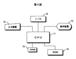
- FIG. 4 is a block diagram showing the electrical configuration of the rope life management apparatus.
- FIG. 5 shows an example of the setting screen.
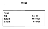
- FIG. 6 shows an example of the operation screen.
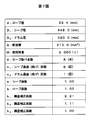
- FIG. 7 shows an example of setting data.
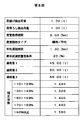
- FIG. 8 shows an example of setting data.
- FIG. 9 is a flowchart showing a processing flow of the rope life management apparatus.
- FIG. 1 shows the schematic structure of a crane that lifts, transports and then unloads a load.
- the crane includes a hoisting and winding drum 1 around which a wire rope 2 is wound. Both ends of the wire rope 2 are fixed near both ends of the winding drum 1.
- the wire rope 2 is fed out from the winding drum 1.
- the winding drum 1 rotates in the reverse direction, the wire rope 2 is rewound onto the winding drum 1.
- the shaft of the winding drum 1 is connected to the winding / rewinding electric motor 2, and the winding drum 1 is rotated forward and backward by the rotational driving of the shaft by the winding / rewinding electric motor 2.
- the crane operator drives the hoisting / rewinding electric motor 2 (control of the rotation direction, control of rotation start and stop, control of the rotation speed, etc.).
- a plurality of sheaves around which the wire rope 2 is wound are provided below the winding drum 1.
- an ecolyzer sheave 3 is arranged at the turn-back position of the wire rope 2, and a fixed sheave 4 and two movable sheaves (hook sheave) are arranged symmetrically across the ecolyzer sheave 3. 5, 6 are arranged.
- a hook 7 is connected to the movable sheaves 5 and 6 to hang a load.
- the wire rope 2 is fed out from the winding drum 1, so that the movable sheaves 5, 6 around which the wire rope 2 is wound move downward.
- the winding drum 1 rotates in the reverse direction, the wire rope 2 is wound around the winding drum 1, so that the movable sheaves 5 and 6 move upward.
- the load hung on the hook 7 is lifted or lowered.
- a load cell 8 for detecting a load applied to the equalizer 3 is attached to the equalizer 3.
- the load cell 8 may be any of a desk type, a compression type, a tension type, an amplifier type, a bearing type, a pin type, and the like.
- a voltage corresponding to the load is output from the load cell 8.
- the voltage output from the load cell 8 is given to the rope life management device 10.
- FIG. 2 shows the data output from the load cell 8 and given to the rope life management device 10 until the load is lifted and then lowered, with the horizontal axis representing time and the vertical axis representing load (voltage corresponding to the load). This is shown by the graph. Details of terms shown in the graph will be described later. As described above, the load hung on the hook 7 is lifted by the crane, moved, and then lowered.
- the ecolyzer sheave 3 Immediately after lifting the load in a stationary state, the ecolyzer sheave 3 is generally subjected to a large load. Immediately after lifting, the load applied to the ecolyzer sheave 3 is larger than the load of the load itself.
- the large load that is temporarily applied to the ecolyzer sheave 3 immediately after lifting is referred to as “shock load”.
- the magnitude of the shock load greatly depends on the skill of the crane operator. When lifting the load, the wire rope 2 is being fed out from the winding drum 1. For this reason, a strong impact is applied to the wire rope 2 by a shock load. When the shock load is large, the degree of damage to the wire rope 2 is greater than when the shock load is small.
- FIG. 3 is a perspective view showing the appearance of the rope life management apparatus 10.
- FIG. 4 is a block diagram showing an electrical configuration of the rope life management apparatus 10.
- a display device 12 having a display panel capable of displaying characters is provided in the upper stage, and an input device 13 having an input panel including a numeric keypad is provided in the lower stage.
- FIG. 5 shows an example of a setting screen displayed on the display panel of the display device 12
- FIG. 6 shows an example of an operation screen displayed on the display panel of the display device 12.
- the input panel of the input device 13 is used to switch between the setting screen and the operation screen.
- a setting screen displayed on the display panel of display device 12 displays a plurality of item names to be input (set). A numerical value corresponding to the item name to be displayed or a code for specifying the numerical value is input using the input device 13.
- the operation screen displayed on the display panel of the display device 12 displays the operation status (actual load of the lifted load, the number of times of use of the wire rope described later (cumulative) Use count), remaining count (remaining usable count), etc. are displayed.
- an input / output port 14 (not visible in FIG. 3) to which the voltage applied from the load cell 8 is input is provided on the back surface of the rope life management device 10.
- the load cell 8 and the input / output port 14 of the rope life management device 10 are electrically connected by a signal line (such as a coaxial cable).
- the rope life management device 10 includes a CPU 11 that generally controls the operation of the rope life management device 10, and the display device 12, the input device 13, and the input / output port 14 described above are connected to the CPU 11.
- the CPU 11 is further connected to a RAM 15 for temporarily storing programs and data, and a ROM 16 for storing setting data, programs, and the like.
- FIGS. 7 and 8 show an example of setting data which is input using the setting screen and stored in the ROM 16 of the rope life management apparatus 10.
- the setting data includes data related to the crane and the wire rope 2 and data related to determination conditions (for example, conditions for determining that unloading / unloading has been performed).
- the setting data shown in FIG. 7 is the setting data regarding the crane and the wire rope 2.
- the setting data relating to crane and wire rope 2 includes the following data.
- Rope diameter d The diameter of the wire rope 2 used in the crane.
- Sheave diameter D1 This is the diameter of a sheave used in the crane (the above-described ecolyzer sheave 3, fixed sheave 4, movable sheave 5, 6).
- Drum diameter D2 The diameter of the winding drum 1.
- Section area A Effective sectional area of the wire rope 2.
- Use load W The maximum value (rated value) of the load that is substantially applied to the wire rope 2 used in the crane. In the case of the crane shown in FIG.
- Number of ropes X The actual number of wire ropes 2 used in the crane, which is obtained by the number of sheaves provided in the crane as described above.
- Number of sheave passage (bending) n 1 This is the number of times one point (predetermined part) of the wire rope 2 passes through the sheave until the load is lifted and lowered (one cycle). In the case of the crane shown in FIG.
- Sheave coefficient a A value (coefficient) determined according to the shape of the groove of the sheave used in the crane (U groove, V groove, undercut groove, etc.). The sheave coefficient a is used for calculation of the remaining usable number of times (estimated life) of the wire rope 2 and the number of times of use of the wire rope 2 (life value subtraction value) using the Neiman formula described later. In general, a sheave having a U-groove is often used for a crane.
- Rope coefficient b a value (coefficient) used for calculating the remaining usable number of times of the wire rope 2 and the number of times of use of the wire rope 2 using the Niemann equation
- the rope coefficient b is defined according to the structure of the wire rope 2 to be used (for example, “normal twist” or “run twist”).
- Structure correction coefficients k 1 , k 2 , k 3 Values (coefficients) used to correct the remaining usable number of times and the number of times of use of the wire rope 2 in accordance with the structure of the wire rope 2, similarly to the rope coefficient b described above. It is.
- the structure correction coefficient k 1 is a value (coefficient) corresponding to the number of strands constituting the wire rope 2.
- Structure correction coefficient k 2 is a value corresponding to the core of the wire rope 2 (whether fiber center is steel core) (coefficient).
- Structure correction coefficient k 3 is either the cross-sectional shape (cross-section of the wire constituting other wire rope 2 structure (wire rope 2 is a circle, whether not circular (deformed lines), the surface of the wire rope 2 It is a value (coefficient) according to whether it is coated.
- Unloading detection load This is a load for determining that a load has been lifted (unloaded) by a crane. When a load greater than the unloading detection load is detected, it is determined that the load has been lifted by the crane.
- Unloading detection load A load for determining that the load has been unloaded (unloaded) after the load has been lifted by the crane. When a load equal to or lower than the unloading detection load is detected, it is determined that the load has been unloaded.
- Load acquisition period With reference to FIG. 2, the predetermined period starting from the acquisition timing of the unloading detection load described above is the load acquisition period.
- Load reading type The load (actual load) of the load lifted by the crane is calculated using the load during the average calculation period.
- the average calculation period is a period starting from the timing when a predetermined period (average delay period) has elapsed from the acquisition timing of the unloading detected load and ending at the end of the load acquisition period.
- a predetermined period average delay period
- the average calculation period is a period starting from the timing when a predetermined period (average delay period) has elapsed from the acquisition timing of the unloading detected load and ending at the end of the load acquisition period.
- Warning condition before the end of life When the estimated remaining number of usable times of the wire rope 2 (estimated remaining life) reaches what percentage of the remaining number of usable times (initial life) when the wire rope 2 is new , Set whether to issue a warning. For example, the warning condition 20% before reaching the end of life means that a warning is issued when the remaining life of the wire rope 2 reaches 80% of the initial life. The warning is performed audibly or visually, such as a warning buzzer or a display on the display device 12.
- Overload 1-3 A warning can be issued even when the actual load of the detected load exceeds the lifting load (rated load) of the crane. Overloads 1 to 3 are loads when this warning is given. Warnings about overloads can be made in several stages. For example, when the lifting load of a crane is 40 tons, a warning is issued when the detected actual load of the load is 45 tons or more, and when the load is 45 to 50 tons, 50 to 55 tons, 55 tons or more In each of the above, the warning sound (or volume) and the display device 12 display are made different to determine which level of overload is applied (which level of load is lifted by the crane). Etc.
- Correction coefficient A value (coefficient) used to correct the number of times the wire rope 2 is used and defined according to the magnitude of the shock load described above (how much the shock load is more than the actual load of the load) ). In this embodiment, when a shock load of 110% or more of the actual load is detected, the rope use frequency correction process using the correction coefficient is performed. Details of the correction process of the number of times of rope use using the correction coefficient will be described later.
- the crane and the setting data (FIG. 7) relating to the wire rope 2 stored in the ROM 16 are used and the rope life management device 10 uses the wire rope in the initial state. 2. The remaining usable number of times (estimated life) is calculated.
- N 1 Based on Neiman equation (bending number of the sheave by the wire rope to the rope rupture) sieve number of passes up the wire rope 2 is broken N 1 is calculated.
- a is the sheave coefficient
- b is the rope coefficient
- D is the sheave diameter
- d is the rope diameter
- ⁇ t is the tensile stress of the wire rope.
- the tensile stress ⁇ t is determined by W / A (W is a working load and A is a rope cross-sectional area).
- the numerical values used for calculating the number of sheave passages N 1 are stored in advance in the ROM 16 (see FIG. 7).
- the number of sheave passages N 2 until the wire rope breaks by 10% is calculated based on the following equation 2 using the safety factor.
- N 2 N 1 ⁇ K 1 ... Formula 2
- K 1 0.6 is used as the safety factor K 1 (1> K 1 ). That is, N 2 ⁇ N 1 .
- the 10% broken sheave passage number N 2 is corrected based on the following equation 3 using the structure correction coefficient K 2 .
- N 3 N 2 ⁇ K 2 Formula 3
- Structure correction factor K 2 is a coefficient determined according to a rope structure of the wire rope 2 to be used is predetermined to correspond to the rope structure.
- the structure correction coefficients k 1 to k 3 (see FIG. 7) stored in advance in the ROM 16 are used as the structure correction coefficient K 2 .
- one of the structure correction coefficients k 1 to k 3 or a combination thereof (for example, a multiplication value) is set as the structure correction coefficient K 2 .
- the N 3 obtained based on the equation 3 above is referred to as a "critical bending count”.
- n 1 is the number of sheave passages of the wire rope 2 per cycle, and as shown in FIG. 7, a numerical value input (set) in advance based on the structure of the crane (number of sheaves) is used.
- the drum diameter (this value is also stored in advance in the ROM 16) (FIG. 7) is used instead of the sheave diameter for D in the Niemann equation of Equation 1.
- n 2 is the number of times the wire rope 2 passes through the drum per cycle (FIG. 7). The remaining usable number of times of the wire rope 2 is calculated on the assumption that fatigue is accumulated by combining the bending of the wire rope in each of the sheave and the drum.
- the final remaining usable number N x of the wire rope 2 is calculated by the following equation using the above-described sheave usable cycle number N a and drum usable cycle number N b .
- 1 / N x (1 / N a ) + (1 / N b )
- N x 1 / ⁇ (1 / N a ) + (1 / N b ) ⁇ Equation 5
- the calculated remaining usable number N x (initial life) of the wire rope 2 in the initial state is stored in the RAM 15 or the ROM 16.
- the remaining usable number of times N x of the obtained wire rope 2 in the initial state is determined according to the operation state of the crane as described below (as described above, the presence / absence of the shock load and its magnitude are considered).
- FIG. 9 is a flowchart showing an operation flow of the rope life management apparatus 10. This will be described with reference to the load data graph shown in FIG.
- a voltage corresponding to the load of the load is output from the load cell 8 and supplied to the rope life management device 10.
- Load data (voltage value) (see FIG. 2) given from the load cell 8 is stored in the RAM 15 of the rope life management device 10 (step 31).
- the determination condition data (setting data) shown in FIG. 8 is used for determining whether the unloading / unloading condition is satisfied. Referring to Fig. 2, a load higher than the unloading detection load was detected, a load lower than the unloading detection load was detected, and a load higher than the unloading detection load and longer than the unloading detection load lasted for the load acquisition period or longer. In this case, it is determined that one work (one cycle) is performed by the crane (YES in step 32).
- a voltage is output from the load cell 8 even when the hook 7 swings due to the influence of wind, but in such a case, the unloading / unloading conditions are not satisfied. If the load data from the load cell 8 does not satisfy the unloading / unloading conditions, the rope life management device 10 does not perform any special processing (NO in step 32).
- load data satisfying the unloading / unloading conditions is given from the load cell 8, it is determined whether or not the maximum value (peak value) (shock load) in the load data exceeds 110% of the actual load (step 33).
- the actual load is a detected load at the end of the average calculation period when “instantaneous” is selected as the load reading type.
- the calculated remaining usable frequency Hremain of the wire rope 2 is the load of the lifted load (actual load), the number of times used so far (cumulative value of the number of times of use calculated every time the crane performs substantial work) Are displayed on the display panel of the display device 12 of the rope life management device 10 (step 36, see FIG. 6).
- the shock load exceeds 110% of the actual load, the wire rope 2 is treated as being damaged by the shock load (YES in step 33).
- the number of times the wire rope 2 is used (life subtraction value) H 1 is multiplied by a correction coefficient (a coefficient exceeding 1) corresponding to the magnitude of the shock load.
- a correction coefficient corresponding to the magnitude of the shock load is set in advance and stored in the ROM 16 as shown in FIG. For example, when the shock load is 115% of the actual load, the result of multiplying the above-described rope use count H 1 by the coefficient 1.240 is treated as the rope use count H 1 .
- the correction factor corresponding to the magnitude of the shock load is obtained using the Niemann equation, taking into account the instantaneous load and the load after unloading the shock load. Since a large value is used as a correction factor as a shock load is large (see FIG. 8), the larger the shock load, rope number of uses (life subtraction value) H 1 becomes large numbers.
- the rope usage count H 1 obtained by subtracting from the remaining usable count N x of the initial state the wire rope 2, to calculate a new remaining usable count Hremain of the wire rope 2 is the same as described above Yes (Formula 7) (Step 34).
- the remaining usable frequency Hremain of the wire rope 2 in consideration of the shock load is displayed on the display panel (step 36).
- the calculation process of the second and subsequent remaining usable count Hremain of the wire rope 2, the rope usage count H 1 that is calculated, of course is subtracted from the remaining usable count Hremain of the wire rope 2 that is previously calculated.
- the remaining usable frequency Hremain of the wire rope 2 is calculated, it is determined whether or not it has reached the set number before the service life (step 37).
- the number of times set before the life is calculated based on a warning condition before the end of life (see FIG. 8) set in advance (of course, it may be calculated in advance and stored in the ROM 16). For example, if the pre-life warning condition is 20%, an 80% value (a value obtained by multiplying 0.8) of the remaining usable number of times of the wire rope 2 in the initial state becomes the pre-life set number. When the calculated remaining usable frequency Hremain of the wire rope 2 becomes equal to or less than the set number before the lifetime, a warning notification such as a warning buzzer and display on the display panel is performed (YES in step 37, step 38).
Landscapes
- Engineering & Computer Science (AREA)
- Mechanical Engineering (AREA)
- Control And Safety Of Cranes (AREA)
Abstract
Description
従来のクレーン用ワイヤロープの寿命予測は,ワイヤロープの曲げ回数(シーブ通過回数)に基づくワイヤロープの疲労度を用いて行われている。これは,クレーンの場合,ほとんどのものでシーブ(滑車)が用いられており,シーブを通過する位置においてワイヤロープの劣化が大きいからである。特許第2748836号公報には,シーブ位置においてワイヤロープの劣化が大きいことを考慮して,ワイヤロープを複数の単位部位に区分して各単位部位ごとに寿命(累積疲労度)を算出する寿命予測装置が記載されている。
クレーンを用いた作業が行われる実際の現場では,ワイヤロープの曲げ回数(シーブ通過回数)以外にも,ワイヤロープの劣化に強く関係する要因が存在する。それは,クレーンを用いて荷物をつり上げたときに一時的に生じる大きな荷重(以下,ショック荷重という)である。ショック荷重の大きさはクレーン運転士の技量に依存する。従来のクレーン用ワイヤロープの寿命予測では,クレーン自体の構造(シーブ数,シーブ径等を含む)を用いた予測にとどまり,ショック荷重によるワイヤロープの寿命への影響は考慮されていない。
この発明によるワイヤロープ寿命管理装置は,ワイヤロープをドラムから繰出し,かつ上記ドラムに巻戻すことによって,上記ワイヤロープおよび上記ワイヤロープが掛けられたシーブを介して荷物をつり上げ,運搬し,その後降ろすクレーンに用いられる上記ワイヤロープの推定寿命(残り使用可能回数)を,所定の寿命推定式にしたがって算出する寿命算出手段,上記シーブに設けられたロードセルから出力される,上記荷物がつり上げられ,その後降ろされるまでの間の上記荷物の荷重データの入力を受付ける荷重データ入力手段,上記荷重データ入力手段から入力された荷重データに基づいて,上記荷物の実荷重を算出する実荷重算出手段,上記荷重データ入力手段から入力された荷重データに基づいて,上記実荷重を所定量以上超えるショック荷重の有無を検知するショック荷重検知手段,および上記ショック荷重検知手段によってショック荷重の存在が検知された場合に,ショック荷重の存在が検知されなかった場合の寿命減算値に1を超える値を持つ補正係数を乗算して得られる値を上記推定寿命から減算することによって,新たなワイヤロープの推定寿命を算出する寿命更新手段を備えるものである。
この発明によるワイヤロープ寿命管理方法は,ワイヤロープをドラムから繰出し,かつ上記ドラムに巻戻すことによって,上記ワイヤロープおよび上記ワイヤロープが掛けられたシーブを介して荷物をつり上げ,運搬し,その後降ろすクレーンに用いられる上記ワイヤロープの推定寿命を,所定の寿命推定式にしたがって算出し,上記シーブに設けられたロードセルから出力される,上記荷物がつり上げられ,その後降ろされるまでの間の上記荷物の荷重データの入力を受付け,入力された荷重データに基づいて,上記荷物の実荷重を算出し,入力された荷重データに基づいて,上記実荷重を所定量以上超えるショック荷重の有無を検知し,ショック荷重の存在が検知された場合に,ショック荷重の存在が検知されなかった場合の寿命減算値に1を超える値を持つ補正係数を乗算して得られた値を上記推定寿命から減算することによって,新たなワイヤロープの推定寿命を算出するものである。
ワイヤロープの推定寿命は所定の寿命推定式にしたがって算出される。この発明は,算出される推定寿命を持つワイヤロープが,現実にクレーンに用いられたときに,その後(クレーンを用いて荷物が運搬された後)にどれだけ寿命が短くなるか(その結果として,ワイヤロープの新たな推定寿命が算出される)を把握するものである。
所定の寿命推定式としては,従来提唱されている種々の寿命推定式のいずれかを用いることができる。たとえば,寿命推定式としてニーマン(Niemann)式を用いて,ワイヤロープの寿命は推定される。もちろん,他の寿命推定式(Zhitkov & Posoekhovの式,E.L.Kleinの式,V.Zignoliの式等)を用いてもよい。上述した種々の寿命推定式については,「ワイヤロープハンドブック」(ワイヤロープハンドブック編集委員会,日刊工業新聞社,1995年3月30日発行,pp.352~353),「ワイヤーロープのすべて(下)−安全への道−」(貝塚商工会議所製鋼活性化研究会,貝塚商工会議所,平成7年7月25日発行,pp.153~158)に記載されている。
シーブに設けられたロードセルから出力される,上記荷物がつり上げられ,その後降ろされるまでの間の上記荷物の荷重データの入力が受け付けられる。荷重データは,荷物がクレーンによってつり上げられ,運搬(移動)され,降ろされるまでの間の連続的な荷重値(ロードセルによる荷重検出値)を含む。荷重データによって経過時間に沿う連続的なグラフを描くことができる。
ロードセルからの荷重データに基づいて,つり上げられた荷物の実荷重が得られる。たとえば,荷物をつり上げてから所定時間を経過した時点の荷重を実荷重としてもよいし,荷物をつり上げてから第1の所定時間を経過した時点からスタートして,その後第2の所定時間が経過する時点までの荷重を平均した値を,実荷重としてもよい。
荷物をつり上げた直後,ロードセルには実荷重を超える荷重がかかる。荷持をつり上げた直後にかかる荷重は,クレーン運転士のクレーン操作に大きく依存する。クレーン運転士が荷物を素早く持ち上げると,ゆっくりと持ち上げた場合と比べて大きな荷重がかかる。
実荷重を所定量以上超える荷重の存在の有無が,荷重データに基づいて検知される。たとえば,実荷重の110%を超える荷重が荷重データ中に現れた場合に,ショック荷重が存在すると判断される。
ショック荷重の存在が検知された場合,ショック荷重の存在が検知されなかった場合の寿命減算値に1を超える値を持つ補正係数を乗算して得られた値を上記推定寿命から減算することによって,新たなワイヤロープの推定寿命が算出される。ショック荷重の存在が検知されなかった場合の寿命減算値としては,たとえば,上記クレーンの最大つり上げ荷重に基づく値を上記ニーマン式に適用することによって得られるワイヤロープの推定寿命を,検出された実荷重に基づく値を上記ニーマン式に適用することによって得られるワイヤロープの推定寿命で除算することによって得られる値が,用いられる。
この発明によると,荷重データ中にショック荷重の存在が検知された場合に,ショック荷重が存在しない場合の寿命減算値に1を超える値を持つ補正係数を乗算して得られた値が上記推定寿命から減算されるので,ショック荷重が存在する場合,ショック荷重が存在しない場合と比較して短い寿命が算出されることになる。ショック荷重の発生に応じて生じるワイヤロープの損傷を考慮した,新たなワイヤロープの推定寿命を算出することができる。
ワイヤロープ寿命管理装置は,算出される新たなワイヤロープの推定寿命を表示する表示装置を備えたものであってもよい。使用中のワイヤロープの交換時期を視覚的に把握することができる。またワイヤロープの推定寿命をリアルタイムに算出して表示し,運転者または現場監督者に知らせることができる。突発的なロープ切れ事故を未然に防止することができる。
好ましくは,ワイヤロープ寿命管理装置は,上記ショック荷重について,上記実荷重を超える超過量を算出するショック荷重超過量算出手段を備え,上記寿命更新手段は,上記補正係数として,上記ショック荷重超過量算出手段によって算出された超過量が大きいほど,大きな値を用いる。ショック荷重の有無のみならず,ショック荷重が存在する場合にはその大きさにも基づいて,新たなワイヤロープの推定寿命を算出することができる。
第2図はロードセルから出力される荷重データを示すグラフである。
第3図はロープ寿命管理装置の外観を示す斜視図である。
第4図はロープ寿命管理装置の電気的構成を示すブロック図である。
第5図は設定画面の一例を示す。
第6図は運転画面の一例を示す。
第7図は設定データの一例を示す。
第8図は設定データの一例を示す。
第9図はロープ寿命管理装置の処理の流れを示すフローチャートである。
クレーンは巻上げ巻上げドラム1を備え,巻上げドラム1にワイヤロープ2が巻回されている。ワイヤロープ2の両端は巻上げドラム1の両端近傍に固定されている。巻上げドラム1が正回転すると,巻上げドラム1からワイヤロープ2が繰出される。巻上げドラム1が逆回転すると,ワイヤロープ2が巻上げドラム1に巻戻される。巻上げドラム1の軸が巻上げ/巻戻し電動機2に連結されており,巻上げ/巻戻し電動機2による軸の回転駆動によって,巻上げドラム1は正回転および逆回転する。クレーン運転士によって,巻上げ/巻戻し電動機2の駆動(回転方向の制御,回転の開始および停止の制御,回転スピードの制御など)は行われる。
巻上げドラム1の下方に,ワイヤロープ2が巻回された複数のシーブが設けられている。第1図に示すクレーンでは,ワイヤロープ2の折返し位置にエコライザ・シーブ3が配置されており,エコライザ・シーブ3を挟んで左右対称に,固定シーブ4,および2つの可動シーブ(フック・シーブ)5,6がそれぞれ配置されている。可動シーブ5,6に荷物を掛けるフック7が連結されている。
巻き上げドラム1が正回転すると,ワイヤロープ2が巻上げドラム1から繰出されるので,ワイヤロープ2が巻回されている可動シーブ5,6が下方に移動する。巻上げドラム1が逆回転すると,ワイヤロープ2が巻上げドラム1に巻取られるので,可動シーブ5,6が上方に移動する。可動シーブ5,6の上昇および下降に伴って,フック7に掛けられた荷物がつり上げられ,または降ろされる。
エコライザ・シーブ3には,エコライザ・シーブ3に加わる荷重を検出するためのロードセル8が取付けられている。ロードセル8はデスク型,圧縮型,引張型,アンプ型,軸受型,ピン型等のいずれであってもよい。荷重に対応する電圧がロードセル8から出力される。ロードセル8から出力された電圧はロープ寿命管理装置10に与えられる。
第2図は,荷物がつり上げられその後降ろされるまでの間に,ロードセル8から出力されてロープ寿命管理装置10に与えられるデータを,横軸を時間,縦軸を荷重(荷重に対応する電圧)としたグラフによって示している。グラフ中に示す用語についての詳細は後述する。
上述のように,フック7に掛けられた荷物は,クレーンによってつり上げられ,移動させられ,その後,降ろされる。静止状態にある荷物をつり上げた直後,エコライザ・シーブ3には一般に大きな荷重が加わる。つり上げ直後にエコライザ・シーブ3に加わる荷重は,荷物自体の荷重よりも大きい。以下,つり上げ直後にエコライザ・シーブ3に一時的に加わる大きな荷重を「ショック荷重」と呼ぶ。ショック荷重の大きさは,クレーン運転士の技量に大きく依存する。
荷物をつり上げるとき,ワイヤロープ2は巻上げドラム1から繰出されている状態である。このため,ワイヤロープ2にはショック荷重によって強い衝撃が加わる。ショック荷重が大きいと,ショック荷重が小さい場合に比べてワイヤロープ2の損傷程度は大きくなる。大きなショック荷重が加え続けられたワイヤロープ2は,そうでないワイヤロープ2に比べて損傷の進行は早い。
ロープ寿命管理装置10は,ワイヤロープ2の使用回数のみならず,ショック荷重の影響をも考慮して,クレーンに使用されているワイヤロープ2の交換時期を予測する(寿命を算出する)ものである。
第3図はロープ寿命管理装置10の外観を示す斜視図である。第4図はロープ寿命管理装置10の電気的構成を示すブロック図である。
ロープ寿命管理装置10の正面には,その上段に文字表示可能な表示パネルを備えた表示装置12が,下段にテンキー等を含む入力パネルを備えた入力装置13が,それぞれ設けられている。表示装置12の表示パネルに,設定画面(設定データの入力に用いられる画面)および運転画面(クレーンの運転状況等を表示するための画面)が表示される。
第5図は表示装置12の表示パネルに表示される設定画面の一例を,第6図は表示装置12の表示パネルに表示される運転画面の一例を,それぞれ示している。入力装置13の入力パネルが用いられて,設定画面と運転画面の切換え等が行われる。
第5図を参照して,表示装置12の表示パネルに表示される設定画面には入力(設定)すべき複数の項目名が表示される。表示される項目名に対応する数値または数値を特定するための符号が入力装置13が用いられて入力される。第6図を参照して,クレーンの運転中または運転後,表示装置12の表示パネルに表示される運転画面に,運転状況(つり上げられた荷物の実荷重,後述するワイヤロープの使用回数(累積使用回数),残り回数(残り使用可能回数)等が表示される。
第3図および第4図に戻って,ロープ寿命管理装置10の背面に,上述したロードセル8から与えられる電圧が入力する入出力ポート14(第3図においては見えない)が設けられている。ロードセル8とロープ寿命管理装置10の入出力ポート14は,信号線(同軸ケーブル等)によって電気的に接続される。
ロープ寿命管理装置10は,ロープ寿命管理装置10の動作を全体的に統括するCPU11を含み,CPU11に上述した表示装置12,入力装置13および入出力ポート14が接続されている。CPU11にはさらに,プログラムおよびデータを一時的に記憶するためのRAM15,ならびに設定データ,プログラム等を記憶するROM16が接続されている。
第7図および第8図は,設定画面を用いて入力され,ロープ寿命管理装置10のROM16に記憶される設定データの一例を示している。
設定データには,クレーンおよびワイヤロープ2に関するデータと,判定条件(たとえば,荷揚げ/荷降しが行われたと判定するための条件)に関するデータとがある。第7図に示す設定データがクレーンおよびワイヤロープ2に関する設定データである。第8図に示す設定データが判定条件に関する設定データである。
第7図を参照して,クレーンおよびワイヤロープ2に関する設定データは,次のデータを含む。
ロープ径d:クレーンに用いられるワイヤロープ2の直径である。
シーブ径D1:クレーンに用いられるシーブ(上述したエコライザ・シーブ3,固定シーブ4,可動シーブ5,6)の直径である。
ドラム径D2:巻上げドラム1の直径である。
断面積A:ワイヤロープ2の有効断面積である。
使用荷重W:クレーンに用いられているワイヤロープ2に実質的に加えられる荷重の最大値(定格値)である。第1図に示すクレーンの場合,ワイヤロープ2は,エコライザ・シーブ3,固定シーブ4,および駆動シーブ5,6に巻回されることによって,8本の掛け本数を持つ(8本のワイヤロープ2に荷重が分散されると取り扱われる)。クレーンのつり上げ荷重(定格荷重)が40トンであるとすると,40/8=5トンがワイヤロープ2についての使用荷重Wとされる。
ロープ掛け本数X:上述のようにクレーンが備えるシーブ数によって得られる,クレーンに用いられているワイヤロープ2の実質的本数である。
シーブ通過(曲げ)回数n1:荷物がつり上げられ,降ろされるまでの間(1サイクル)に,ワイヤロープ2の一点(所定部位)がシーブを通過する回数である。第1図に示すクレーンの場合には,エコライザ・シーブ3を挟んで3つのシーブ(固定シーブ4および2つの可動シーブ5,6)が配置されているので,つり上げのときに3回,降ろされるときに3回,ワイヤロープ2はシーブを通過する(合計6回)。第1図に示すクレーンのシーブ通過(曲げ)回数は6回とされる。
ドラム通過(曲げ)回数n2:荷物がつり上げられ,降ろされるまでの間(1サイクル)に,ワイヤロープ2の一点(所定部位)が巻上げドラム1を通過する回数である。第1図に示すクレーンの場合,巻上げドラム1は一つであるので,ワイヤロープ2は1サイクル中にドラムを1回通過する。第1図に示すクレーンのドラム通過(曲げ)回数は1回とされる。
シーブ係数a:クレーンに用いられるシーブの溝の形状(U溝,V溝,アンダカット溝等)に応じて決定される値(係数)である。シーブ係数aは,後述するニーマン式を用いたワイヤロープ2の残り使用可能回数(推定寿命)およびワイヤロープ2の使用回数(寿命減算値)の演算に用いられる。なお,一般にクレーンに用いられるシーブにはU溝を持つものが用いられることが多い。
ロープ係数b:ニーマン式を用いたワイヤロープ2の残り使用可能回数およびワイヤロープ2の使用回数の演算に用いられる値(係数)である。ロープ係数bは使用されるワイヤロープ2の構造(たとえば「普通撚り」であるか「ラング撚り」であるか)に応じて規定される。
構造補正係数k1,k2,k3:上述のロープ係数bと同様,ワイヤロープ2の構造に応じてワイヤロープ2の残り使用可能回数および使用回数を補正するために用いられる値(係数)である。構造補正係数k1はワイヤロープ2を構成するストランドの本数等に応じた値(係数)である。構造補正係数k2はワイヤロープ2の心材(鋼心であるか繊維心であるか)に応じた値(係数)である。構造補正係数k3はその他のワイヤロープ2の構造(ワイヤロープ2を構成する素線の断面形状(断面が円であるか,円でないか(異形線であるか),ワイヤロープ2の表面がコートされているか等)に応じた値(係数)である。
第8図を参照して,判定条件に関する設定データは,次のデータを含む。
荷揚げ検出荷重:クレーンによって荷物のつり上げ(荷揚げ)が行われたと判定するための荷重である。荷揚げ検出荷重以上の荷重が検出された場合に,クレーンによって荷物がつり上げられたと判定される。
荷降ろし検出荷重:クレーンによって荷物がつり上げられた後,その荷物が降ろされた(荷降ろしが行われた)と判定するための荷重である。荷降ろし検出荷重以下の荷重が検出された場合に,荷物が降ろされたと判断される。
荷重取得期間:第2図を参照して,上述した荷揚げ検出荷重の取得のタイミングから始まる所定期間が,荷重取得期間である。上述した荷揚げ検出荷重以上の荷重が検出され,かつ荷降ろし検出荷重以下の荷重が検出され,かつ荷揚げ検出荷重以上荷降ろし検出荷重以上の荷重が,この荷重取得期間以上継続して検出された場合に,クレーンによる一回の仕事,すなわち荷物をつり上げ,運搬し,その後に降ろす一連の作業(1サイクル)が行われた(荷揚げおよび荷降し条件を満たす)と,判定される。
荷重読取タイプ:クレーンによってつり上げられた荷物の荷重(実荷重)は,平均演算期間中の荷重を用いて算出される。ここで平均演算期間は,第2図を参照して,荷揚げ検出荷重の取得タイミングから所定期間(平均遅延期間)が経過したタイミングから始まり,上記荷重取得期間の終了のタイミングで終わる期間である。荷重読取タイプとしては,「瞬時」および「平均」のいずれかを選択することができる。「瞬時」が選択されると,平均演算期間の終了時(荷重取得期間の終了時と同じ)のタイミングでの検出荷重が,クレーンがつり上げた荷物の荷重(実荷重)として扱われる。「平均」が選択されると,平均演算期間中の検出荷重の平均値が,クレーンがつり上げた荷物の荷重(実荷重)として扱われる。
平均遅延期間:上述したように,荷揚げ検出荷重の取得タイミングから始まり,荷重取得期間の終了のタイミングで終わる期間である(第2図参照)。この平均遅延期間中に,上述したショック荷重(ピーク値)が収まる。
寿命到達前警告条件:予測されるワイヤロープ2の残り使用可能回数(推定される残り寿命)が,ワイヤロープ2が新品のときの残り使用可能回数(初期寿命)の何%に達したときに,警告を発するかを設定するものである。たとえば,寿命到達前警告条件20%は,ワイヤロープ2の残り寿命が初期寿命の80%に達したときに警告を発することを意味する。警告は,警告ブザー,表示装置12上における表示など,聴覚的または視覚的に行われる。
過荷重1~3:検出された荷物の実荷重がクレーンのつり上げ荷重(定格荷重)を上回ったときにも,警告を行うことができる。過荷重1~3は,この警告を行うときの荷重である。過荷重に関する警告は,複数の段階(レベル)で行うことができる。たとえば,クレーンのつり上げ荷重が40トンの場合,検出された荷物の実荷重が45トン以上の場合に警告が行われ,45トン以上50トン未満,50トン以上55トン未満,55トン以上の場合のそれぞれにおいて,警告音(または音量),表示装置12の表示を異ならせることによって,いずれのレベルの過荷重が加わったか(いずれのレベルの荷重の荷物がクレーンによってつり上げられたか)が,運転者等に報知される。
補正係数:ワイヤロープ2の使用回数を補正するために用いられ,上述したショック荷重の大きさ(ショック荷重が,荷物の実荷重の何%以上であるか)に応じて規定される値(係数)である。この実施例では,実荷重の110%以上のショック荷重が検知された場合に,補正係数を用いたロープ使用回数の補正処理が行われる。補正係数を用いたロープ使用回数の補正処理の詳細は後述する。
ワイヤロープ2をクレーンにセットしてクレーンを稼働させる前に,ROM16に記憶されたクレーンおよびワイヤロープ2に関する設定データ(第7図)が用いられて,ロープ寿命管理装置10によって初期状態におけるワイヤロープ2の残り使用可能回数(推定寿命)が算出される。
この実施例では,従来知られている複数の演算式のうち,ニーマン(G.Niemann)式を用いたワイヤロープの残り使用可能回数の算出を説明する。ニーマン式についての詳細は,たとえば,「ワイヤロープハンドブック」ワイヤロープハンドブック編集委員会,日刊工業新聞社,1995年3月30日発行,pp.352~353),「ワイヤーロープのすべて(下)−安全への道−」(貝塚商工会議所製鋼活性化研究会,貝塚商工会議所,平成7年7月25日発行,pp.153~158)に記載されている。
ニーマン式は式1に示すとおりである。ニーマン式に基づいて,ワイヤロープ2が破断するまでのシーブ通過回数(ロープ破断までのシーブによるワイヤロープの曲げ回数)N1が算出される。

次に,ワイヤロープが10%断線するまでのシーブ通過回数N2が,安全係数を用いて,次の式2に基づいて算出される。なお,「10%断線」とは安全性を考慮して用いられる概念であり,ワイヤロープが完全に断線したときを100%断線と考え,その10分の1程度の断線状態を想定するものである。
N2=N1×K1 ・・・式2
安全係数K1(1>K1)として,たとえば,K1=0.6が用いられる。すなわち,N2<N1である。
次に,ロープ構成に基づく疲労性差を考慮して,10%断線シーブ通過回数N2が,構造補正係数K2を用いて,次に示す式3に基づいて補正される。
N3=N2×K2 ・・・式3
構造補正係数K2は,使用されるワイヤロープ2のロープ構造に応じて定められる係数であり,ロープ構造に対応してあらかじめ定められている。ROM16にあらかじめ記憶されている構造補正係数k1~k3(第7図参照)が,構造補正係数K2として用いられる。クレーンに用いられているワイヤロープ2の構造に応じて,構造補正係数k1~k3のいずれかまたはその組合わせ(たとえば乗算値)が,構造補正係数K2とされる。
以下では,上記の式3に基づいて得られるN3を,「限界曲げ回数」と呼ぶ。
クレーンの1サイクル(荷物をつり上げ,移動させ,その後降ろすこと)あたりのワイヤロープ2の曲げ回数(1サイクルあたりのシーブ通過回数)を用いて,上記限界曲げ回数N3を除算することによって,シーブについての使用可能サイクル数Na(荷物をつり上げ,移動させ,その後に降ろすサイクルを,何回繰り返すことができるかを表す数値)が算出される。
シーブ使用可能サイクル数Na=N3/n1 ・・・式4
ここでn1は1サイクルあたりのワイヤロープ2のシーブ通過回数であり,第7図に示すように,クレーンの構造(シーブ数)に基づいてあらかじめ入力(設定)された数値が用いられる。
上述と同様にして,巻上げドラム1についてのドラム使用可能サイクル数Nb(=N3/n2)も算出される。式1のニーマン式におけるDに,シーブ径ではなく,ドラム径(この値もROM16にあらかじめ記憶されている)(第7図)が用いられる点のみが異なる。なお,n2は1サイクルあたりのワイヤロープ2のドラム通過回数である(第7図)。
ワイヤロープ2の残り使用可能回数は,シーブおよびドラムのそれぞれにおけるワイヤロープの曲げが複合されて疲労が蓄積されることを仮定した上で算出される。最終的なワイヤロープ2の残り使用可能回数Nxは,上述したシーブ使用可能サイクル数Naおよびドラム使用可能サイクル数Nbを用いて,次式によって算出される。
1/Nx=(1/Na)+(1/Nb)
Nx=1/{(1/Na)+(1/Nb)} ・・・式5
算出された初期状態のワイヤロープ2の残り使用可能回数Nx(初期寿命)は,RAM15またはROM16に記憶される。
得られた初期状態のワイヤロープ2の残り使用可能回数Nxが,次に説明するように,クレーンの運転状況に応じて(上述のように,ショック荷重の有無およびその大きさが考慮された上で)減算され,新たなワイヤロープ2の残り使用可能回数(残り寿命,推定寿命)が算出されることになる。
第9図は,ロープ寿命管理装置10の動作の流れを示すフローチャートである。第2図に示す荷重データのグラフを参照しつつ説明する。
クレーンが稼働すると,ロードセル8から荷物の荷重に応じた電圧が出力され,ロープ寿命管理装置10に供給される。ロープ寿命管理装置10のRAM15に,ロードセル8から与えられる荷重データ(電圧値)(第2図参照)が記憶される(ステップ31)。
はじめに,荷揚げ/荷降ろし条件を満たすかどうかが判断される(ステップ32)。これは,クレーンが実質的に仕事(荷物をつり上げ,移動させ,降ろす1サイクルの動作)を行ったことを条件にして,ワイヤロープの寿命管理を行うためである。
荷揚げ/荷降ろし条件を満たすかどうかの判断には,第8図に示す判定条件データ(設定データ)が用いられる。第2図を参照して,荷揚げ検出荷重以上の荷重が検出され,かつ荷降ろし検出荷重以下の荷重が検出され,かつ荷揚げ検出荷重以上荷降ろし検出荷重以上の荷重が,荷重取得期間以上続いた場合に,クレーンによる一回の仕事(1サイクル)が行われたと判定される(ステップ32でYES)。
たとえば,風の影響によってフック7が揺動した場合にもロードセル8から電圧が出力されるが,このような場合は荷揚げ/荷降ろし条件を満たさない。ロードセル8からの荷重データが荷揚げ/荷降ろし条件を満たさない場合,ロープ寿命管理装置10は特段の処理を行わない(ステップ32でNO)。
荷揚げ/荷降ろし条件を満たす荷重データがロードセル8から与えられた場合,荷重データ中の最大値(ピーク値)(ショック荷重)が,実荷重の110%を超えるかどうかが判断される(ステップ33)。実荷重は,上述したように,荷重読取りタイプとして「瞬時」が選択されている場合は平均演算期間の終了時における検出荷重である。「平均」が選択されている場合には平均演算期間中の検出荷重の平均値である。
ショック荷重が実荷重の110%以下である場合,ショック荷重によるワイヤロープ2への影響はない(ショック荷重はない)と扱われる(ステップ33でNO)。
この場合には,一般的なロープ使用回数減算処理(残り使用可能回数算出処理)に進む(ステップ35)。
ロープ使用回数減算処理(ステップ35)では,次の計算が行われる。
はじめに,ロードセル8からの荷重データに基づいて得られた実荷重が用いられて,式1~式5にしたがってワイヤロープ2の残り使用可能回数N1が算出される。上述した初期状態のワイヤロープ2の残り使用可能回数Nxは,ニーマン式に用いられる引張応力σt(=W/A)として,クレーンで持ち上げることができるつり上げ荷重(定格荷重)に基づく使用荷重W(たとえば,クレーンのつり上げ荷重が40トンであり,第1図に示す構造のクレーンの場合,使用荷重W=5トン)(第7図参照)を用いて算出されたものである。これに対し,実際につり上げられる荷物の荷重は,つり上げ荷重よりも軽い(または重い)場合もある。たとえば,40トン・クレーンで40トンの荷物を取り扱ったとすると,そのときに1回のワイヤロープ2の使用が行われたとされるが,40トンよりも軽い(たとえば,30トン)の荷物が取り扱われたとすると,1回に満たないワイヤロープ2の使用が行われたと扱われる。
ワイヤロープ2の使用回数(寿命減算値)H1は,式6によって算出される。
H1=Nx/N1 ・・・式6
ワイヤロープ2についての新たな残り使用可能回数(残り寿命,推定寿命)Hremainは,式7によって算出される。
Hremain=Nx−H1 ・・・式7
算出されたワイヤロープ2の残り使用可能回数Hremainが,つり上げられた荷物の荷重(実荷重),これまでの使用回数(クレーンが実質的な仕事をするたびに算出される使用回数の累積値)等とともに,ロープ寿命管理装置10の表示装置12の表示パネルに表示される(ステップ36,第6図参照)。
他方,ショック荷重が実荷重の110%を超えた場合には,ショック荷重によってワイヤロープ2は損傷を受けるとして扱われる(ステップ33でYES)。
この場合,上述のワイヤロープ2の使用回数(寿命減算値)H1として,ショック荷重の大きさに応じた補正係数(1を超える係数)を乗算したものが用いられる。
ショック荷重の大きさに応じた補正係数は,第8図に示すように,あらかじめ設定されてROM16に記憶されている。たとえば,ショック荷重が実荷重の115%であった場合,上述したロープ使用回数H1に係数1.240が乗算された結果が,ロープ使用回数H1として扱われる。ショック荷重の大きさに応じた補正係数は,瞬時に働いた負荷量と,ショック荷重除荷後の負荷量を考慮して,ニーマン式を使用して求めている。
ショック荷重が大きいほど補正係数として大きな値が用いられる(第8図参照)ので,ショック荷重が大きければ大きいほど,ロープ使用回数(寿命減算値)H1は大きな数値となる。
得られたロープ使用回数H1を,初期状態のワイヤロープ2の残り使用可能回数Nxから減算することによって,ワイヤロープ2の新たな残り使用可能回数Hremainを算出するのは,上述と同様である(式7)(ステップ34)。ショック荷重が考慮されたワイヤロープ2の残り使用可能回数Hremainが,表示パネルに表示される(ステップ36)。
2回目以降のワイヤロープ2の残り使用可能回数Hremainの算出処理では,算出されたロープ使用回数H1が,前回算出されたワイヤロープ2の残り使用可能回数Hremainから減算されるのは言うまでもない。
ワイヤロープ2の残り使用可能回数Hremainが算出されると,それが寿命前設定回数に達しているかどうかが判断される(ステップ37)。寿命前設定回数は,あらかじめ設定されている寿命到達前警告条件(第8図参照)に基づいて算出される(もちろん,あらかじめ算出してROM16に記憶しておいてもよい)。たとえば,寿命到達前警告条件が20%であれば,初期状態のワイヤロープ2の残り使用可能回数の80%値(0.8を乗算した値)が寿命前設定回数となる。算出されたワイヤロープ2の残り使用可能回数Hremainが上記寿命前設定回数以下になると,警告ブザー,表示パネル上における表示などの警告報知が行われる(ステップ37でYES,ステップ38)。
Claims (5)
- ワイヤロープをドラムから繰出し,かつ上記ドラムに巻戻すことによって,上記ワイヤロープおよび上記ワイヤロープが掛けられたシーブを介して荷物をつり上げ,運搬し,その後降ろすクレーンに用いられる上記ワイヤロープの推定寿命を,所定の寿命推定式にしたがって算出する寿命算出手段,
上記シーブに設けられたロードセルから出力される,上記荷物がつり上げられ,その後降ろされるまでの間の上記荷物の荷重データの入力を受付ける荷重データ入力手段,
上記荷重データ入力手段から入力された荷重データに基づいて,上記荷物の実荷重を算出する実荷重算出手段,
上記荷重データ入力手段から入力された荷重データに基づいて,上記実荷重を所定量以上超えるショック荷重の有無を検知するショック荷重検知手段,および
上記ショック荷重検知手段によってショック荷重の存在が検知された場合に,ショック荷重の存在が検知されなかった場合の寿命減算値に1を超える値を持つ補正係数を乗算して得られた値を上記推定寿命から減算することによって,新たなワイヤロープの推定寿命を算出する寿命更新手段,
を備えるワイヤロープ寿命管理装置。 - 上記ショック荷重について,上記実荷重を超える超過量を算出するショック荷重超過量算出手段を備え,
上記寿命更新手段は,
上記補正係数として,上記ショック荷重超過量算出手段によって算出された超過量が大きいほど,大きな値を用いる,
請求の範囲第1項に記載のワイヤロープ寿命管理装置。 - 上記寿命更新手段によって算出される新たなワイヤロープの推定寿命を表示する表示装置を備える,
請求の範囲第1項または第2項に記載のワイヤロープ寿命管理装置。 - 上記所定の寿命推定式としてニーマン式を用いる,
請求の範囲第1項から第3項のいずれか一項に記載のワイヤロープ寿命管理装置。 - ワイヤロープをドラムから繰出し,かつ上記ドラムに巻戻すことによって,上記ワイヤロープおよび上記ワイヤロープが掛けられたシーブを介して荷物をつり上げ,運搬し,その後降ろすクレーンに用いられる上記ワイヤロープの推定寿命を,所定の寿命推定式にしたがって算出し,
上記シーブに設けられたロードセルから出力される,上記荷物がつり上げられ,その後降ろされるまでの間の上記荷物の荷重データの入力を受付け,
入力された荷重データに基づいて,上記荷物の実荷重を算出し,
入力された荷重データに基づいて,上記実荷重を所定量以上超えるショック荷重の有無を検知し,
ショック荷重の存在が検知された場合に,ショック荷重の存在が検知されなかった場合の寿命減算値に1を超える値を持つ補正係数を乗算して得られた値を上記推定寿命から減算することによって,新たなワイヤロープの推定寿命を算出する,
ワイヤロープ寿命管理方法。
Priority Applications (3)
| Application Number | Priority Date | Filing Date | Title |
|---|---|---|---|
| SG2011062106A SG174173A1 (en) | 2009-03-05 | 2010-03-05 | Wire rope life management device and method |
| CN2010800106383A CN102341338B (zh) | 2009-03-05 | 2010-03-05 | 钢丝绳寿命管理装置和方法 |
| KR1020117023035A KR101321193B1 (ko) | 2009-03-05 | 2010-03-05 | 와이어 로프 수명 관리 장치 및 방법 |
Applications Claiming Priority (2)
| Application Number | Priority Date | Filing Date | Title |
|---|---|---|---|
| JP2009051807A JP5270404B2 (ja) | 2009-03-05 | 2009-03-05 | ワイヤロープ寿命管理装置および方法 |
| JP2009-051807 | 2009-03-05 |
Publications (1)
| Publication Number | Publication Date |
|---|---|
| WO2010101305A1 true WO2010101305A1 (ja) | 2010-09-10 |
Family
ID=42709841
Family Applications (1)
| Application Number | Title | Priority Date | Filing Date |
|---|---|---|---|
| PCT/JP2010/054167 Ceased WO2010101305A1 (ja) | 2009-03-05 | 2010-03-05 | ワイヤロープ寿命管理装置および方法 |
Country Status (6)
| Country | Link |
|---|---|
| JP (1) | JP5270404B2 (ja) |
| KR (1) | KR101321193B1 (ja) |
| CN (1) | CN102341338B (ja) |
| MY (1) | MY166567A (ja) |
| SG (1) | SG174173A1 (ja) |
| WO (1) | WO2010101305A1 (ja) |
Cited By (2)
| Publication number | Priority date | Publication date | Assignee | Title |
|---|---|---|---|---|
| JP2016529182A (ja) * | 2013-08-27 | 2016-09-23 | リープヘル−コンポーネンツ ビーベラッハ ゲーエムベーハー | ホイストに用いられる高強度繊維ロープの廃棄状態を検出する装置 |
| CN119349155A (zh) * | 2024-12-19 | 2025-01-24 | 山西华智弘兴科技有限公司 | 一种具备钢丝绳芯输送带接头抽动检测功能的输送机系统 |
Families Citing this family (15)
| Publication number | Priority date | Publication date | Assignee | Title |
|---|---|---|---|---|
| KR101225655B1 (ko) * | 2010-11-23 | 2013-02-28 | 헤스본주식회사 | 와이어 수명 모니터링 기능이 구비된 4주식 리프트 |
| JP5574354B2 (ja) | 2012-03-09 | 2014-08-20 | 株式会社トヨコー | 塗膜除去方法及びレーザー塗膜除去装置 |
| CN103112781B (zh) * | 2013-02-20 | 2014-12-17 | 大连博瑞重工有限公司 | 起重机钢丝绳弯折次数记录和计算方法 |
| JP6054795B2 (ja) * | 2013-03-29 | 2016-12-27 | 株式会社日立産機システム | 巻上機寿命計算装置 |
| CN103935896B (zh) * | 2014-03-28 | 2016-07-06 | 广西柳工机械股份有限公司 | 起重机械钢丝绳倍率自动识别装置及识别方法 |
| CN104401874B (zh) * | 2014-10-11 | 2016-02-03 | 太原科技大学 | 起重机起升钢丝绳全程实时寿命的评估方法 |
| CN105725299A (zh) * | 2016-04-01 | 2016-07-06 | 德清申力索具有限公司 | 一种安全衣 |
| JP7152226B2 (ja) * | 2018-09-12 | 2022-10-12 | 株式会社日立産機システム | ワイヤーロープ監視装置およびワイヤーロープ監視方法 |
| CN109684784B (zh) * | 2019-02-28 | 2022-06-07 | 攀钢集团攀枝花钢钒有限公司 | 起重机钢丝绳寿命监测方法 |
| DE102019122703A1 (de) * | 2019-08-23 | 2021-02-25 | Johannes Hübner Fabrik elektrischer Maschinen GmbH | Steuereinheit und Verfahren zum Betrieb eines Fördermittels |
| JP7553287B2 (ja) * | 2019-09-10 | 2024-09-18 | 住友重機械搬送システム株式会社 | クレーンの作業管理システム、及び管理装置 |
| KR102364170B1 (ko) * | 2019-11-28 | 2022-02-18 | 한국조선해양 주식회사 | 크레인 와이어로프의 수명예측시스템 |
| KR102592161B1 (ko) * | 2021-03-05 | 2023-10-19 | 오철규 | 지능형 크레인 안전 관리 시스템 |
| CN115983838B (zh) * | 2023-03-21 | 2023-07-14 | 江苏苏港智能装备产业创新中心有限公司 | 起重机起升机构钢丝绳健康评估方法、装置、设备及存储介质 |
| CN119079822A (zh) * | 2024-10-08 | 2024-12-06 | 中国人民解放军火箭军工程大学 | 一种起重钢丝绳载荷在线监测装置及其应用 |
Citations (3)
| Publication number | Priority date | Publication date | Assignee | Title |
|---|---|---|---|---|
| JPH07172763A (ja) * | 1993-12-16 | 1995-07-11 | Nkk Corp | クレーン用ワイヤーロープの寿命予測方法及びその装置 |
| JP2005170668A (ja) * | 2003-12-15 | 2005-06-30 | Mitsubishi Heavy Ind Ltd | ワイヤ荷重変動低減装置を備えたクレーン |
| JP2005231827A (ja) * | 2004-02-20 | 2005-09-02 | Hitachi Kiden Kogyo Ltd | クレーンの故障診断装置 |
Family Cites Families (6)
| Publication number | Priority date | Publication date | Assignee | Title |
|---|---|---|---|---|
| JPS58220085A (ja) * | 1982-06-16 | 1983-12-21 | 株式会社日立製作所 | クレ−ンの荷重検出装置 |
| JPH0570089A (ja) * | 1991-09-05 | 1993-03-23 | Sumitomo Heavy Ind Ltd | 誘導電動機用制御装置 |
| JP4068213B2 (ja) * | 1998-05-12 | 2008-03-26 | 三菱電機株式会社 | 可変速巻上装置 |
| GB0515176D0 (en) * | 2005-07-23 | 2005-08-31 | Renold Plc | Transmission chain monitoring system |
| CN201037100Y (zh) * | 2007-02-12 | 2008-03-19 | 索成将 | 绞车计数和测力装置 |
| CN101077756B (zh) * | 2007-06-23 | 2010-10-06 | 深圳市中信康特种设备技术有限公司 | 一种起重设备远程实时安全监管系统及其控制方法 |
-
2009
- 2009-03-05 JP JP2009051807A patent/JP5270404B2/ja active Active
-
2010
- 2010-03-05 WO PCT/JP2010/054167 patent/WO2010101305A1/ja not_active Ceased
- 2010-03-05 MY MYPI2011004103A patent/MY166567A/en unknown
- 2010-03-05 CN CN2010800106383A patent/CN102341338B/zh not_active Expired - Fee Related
- 2010-03-05 KR KR1020117023035A patent/KR101321193B1/ko not_active Expired - Fee Related
- 2010-03-05 SG SG2011062106A patent/SG174173A1/en unknown
Patent Citations (3)
| Publication number | Priority date | Publication date | Assignee | Title |
|---|---|---|---|---|
| JPH07172763A (ja) * | 1993-12-16 | 1995-07-11 | Nkk Corp | クレーン用ワイヤーロープの寿命予測方法及びその装置 |
| JP2005170668A (ja) * | 2003-12-15 | 2005-06-30 | Mitsubishi Heavy Ind Ltd | ワイヤ荷重変動低減装置を備えたクレーン |
| JP2005231827A (ja) * | 2004-02-20 | 2005-09-02 | Hitachi Kiden Kogyo Ltd | クレーンの故障診断装置 |
Cited By (2)
| Publication number | Priority date | Publication date | Assignee | Title |
|---|---|---|---|---|
| JP2016529182A (ja) * | 2013-08-27 | 2016-09-23 | リープヘル−コンポーネンツ ビーベラッハ ゲーエムベーハー | ホイストに用いられる高強度繊維ロープの廃棄状態を検出する装置 |
| CN119349155A (zh) * | 2024-12-19 | 2025-01-24 | 山西华智弘兴科技有限公司 | 一种具备钢丝绳芯输送带接头抽动检测功能的输送机系统 |
Also Published As
| Publication number | Publication date |
|---|---|
| JP5270404B2 (ja) | 2013-08-21 |
| CN102341338A (zh) | 2012-02-01 |
| KR101321193B1 (ko) | 2013-10-23 |
| KR20110133585A (ko) | 2011-12-13 |
| JP2010202377A (ja) | 2010-09-16 |
| MY166567A (en) | 2018-07-17 |
| CN102341338B (zh) | 2013-12-11 |
| SG174173A1 (en) | 2011-10-28 |
Similar Documents
| Publication | Publication Date | Title |
|---|---|---|
| JP5270404B2 (ja) | ワイヤロープ寿命管理装置および方法 | |
| US7416169B2 (en) | Hoisting-cable drive comprising a single bottom-hook block and two winches | |
| CN102818712B (zh) | 绞车试验装置和方法 | |
| JP6435162B2 (ja) | クレーンのワイヤロープ疲労度計測方法及び装置 | |
| US8669724B2 (en) | Method and apparatus for load dependent speed control of a motor | |
| US10870560B2 (en) | Crane | |
| JP6747633B1 (ja) | クレーン装置、掛数判定方法及びプログラム | |
| JP5759938B2 (ja) | エレベータのロープ点検方法 | |
| JP2001192183A (ja) | 合成繊維ロープの劣化状態判別方法およびエレベータ | |
| CN109715547A (zh) | 电动卷扬机装置 | |
| CN103693562B (zh) | 起重机穿绳卷扬的控制方法、装置、系统及穿绳设备 | |
| KR101691265B1 (ko) | 엘리베이터의 권상능력평가 및 브레이크 제동력 측정장치 | |
| KR100958298B1 (ko) | 승강기 언밸런스하중 및 최대적재하중 측정방법 및 장치 | |
| JP7346354B2 (ja) | ワイヤロープ監視装置およびクレーンシステム | |
| JP5809788B2 (ja) | 地切り停止機構付き電動巻上機 | |
| JPH11246178A (ja) | クレーンの過負荷防止方法およびその過負荷防止装置 | |
| JP2004251880A (ja) | ワイヤロープ寿命判定方法 | |
| JPH04292389A (ja) | 昇降架台の落下防止装置 | |
| CN115108484A (zh) | 用于辅助维护吊运或运输设备的金属缆绳的方法 | |
| JP2019104551A (ja) | 移動式クレーン | |
| JPH11139760A (ja) | 移動式クレーンの吊り荷荷重検出装置 | |
| JPH107323A (ja) | ワイヤロープの寿命判定方法および装置 | |
| JP2007204266A (ja) | クレーンの過負荷防止装置 | |
| JPH0597397A (ja) | 物揚げ装置のワイヤロープ曲げ回数監視方法 | |
| JPH06345388A (ja) | ワイヤーロープの寿命算出装置 |
Legal Events
| Date | Code | Title | Description |
|---|---|---|---|
| WWE | Wipo information: entry into national phase |
Ref document number: 201080010638.3 Country of ref document: CN |
|
| 121 | Ep: the epo has been informed by wipo that ep was designated in this application |
Ref document number: 10748891 Country of ref document: EP Kind code of ref document: A1 |
|
| NENP | Non-entry into the national phase |
Ref country code: DE |
|
| ENP | Entry into the national phase |
Ref document number: 20117023035 Country of ref document: KR Kind code of ref document: A |
|
| 122 | Ep: pct application non-entry in european phase |
Ref document number: 10748891 Country of ref document: EP Kind code of ref document: A1 |