WO2010100914A1 - 液体クロマトグラフ及び分析方法 - Google Patents
液体クロマトグラフ及び分析方法 Download PDFInfo
- Publication number
- WO2010100914A1 WO2010100914A1 PCT/JP2010/001453 JP2010001453W WO2010100914A1 WO 2010100914 A1 WO2010100914 A1 WO 2010100914A1 JP 2010001453 W JP2010001453 W JP 2010001453W WO 2010100914 A1 WO2010100914 A1 WO 2010100914A1
- Authority
- WO
- WIPO (PCT)
- Prior art keywords
- reaction reagent
- mobile phase
- separation column
- liquid
- unit
- Prior art date
- Legal status (The legal status is an assumption and is not a legal conclusion. Google has not performed a legal analysis and makes no representation as to the accuracy of the status listed.)
- Ceased
Links
Images






Classifications
-
- G—PHYSICS
- G01—MEASURING; TESTING
- G01N—INVESTIGATING OR ANALYSING MATERIALS BY DETERMINING THEIR CHEMICAL OR PHYSICAL PROPERTIES
- G01N30/00—Investigating or analysing materials by separation into components using adsorption, absorption or similar phenomena or using ion-exchange, e.g. chromatography or field flow fractionation
- G01N30/02—Column chromatography
- G01N30/84—Preparation of the fraction to be distributed
-
- G—PHYSICS
- G01—MEASURING; TESTING
- G01N—INVESTIGATING OR ANALYSING MATERIALS BY DETERMINING THEIR CHEMICAL OR PHYSICAL PROPERTIES
- G01N30/00—Investigating or analysing materials by separation into components using adsorption, absorption or similar phenomena or using ion-exchange, e.g. chromatography or field flow fractionation
- G01N30/02—Column chromatography
- G01N30/26—Conditioning of the fluid carrier; Flow patterns
- G01N30/28—Control of physical parameters of the fluid carrier
- G01N30/32—Control of physical parameters of the fluid carrier of pressure or speed
-
- G—PHYSICS
- G01—MEASURING; TESTING
- G01N—INVESTIGATING OR ANALYSING MATERIALS BY DETERMINING THEIR CHEMICAL OR PHYSICAL PROPERTIES
- G01N30/00—Investigating or analysing materials by separation into components using adsorption, absorption or similar phenomena or using ion-exchange, e.g. chromatography or field flow fractionation
- G01N30/02—Column chromatography
- G01N30/84—Preparation of the fraction to be distributed
- G01N2030/8429—Preparation of the fraction to be distributed adding modificating material
- G01N2030/8435—Preparation of the fraction to be distributed adding modificating material for chemical reaction
-
- G—PHYSICS
- G01—MEASURING; TESTING
- G01N—INVESTIGATING OR ANALYSING MATERIALS BY DETERMINING THEIR CHEMICAL OR PHYSICAL PROPERTIES
- G01N30/00—Investigating or analysing materials by separation into components using adsorption, absorption or similar phenomena or using ion-exchange, e.g. chromatography or field flow fractionation
- G01N30/02—Column chromatography
- G01N30/62—Detectors specially adapted therefor
- G01N30/74—Optical detectors
Definitions
- the present invention relates to a liquid chromatograph and an analysis method using a post-column method.
- Liquid chromatography using the post-column method is an analysis method in which one or more reaction reagents are mixed with the sample eluted from the separation column, and the resulting reaction product is detected. And are often used to measure substances that do not have UV absorption.
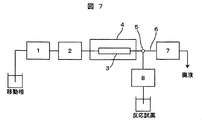
- FIG. 7 is a block diagram of a conventional high performance liquid chromatograph using a post column method.
- the high-performance liquid chromatograph includes a mobile phase feed pump 1, an injector 2 for injecting a sample, a separation column 3 for separating a sample, a column oven 4 for keeping the separation column 3 at a constant temperature, and a sample eluted from the separation column 3 T joint 5 with a three-way joint structure for mixing reagents, piping 6 flowing while the sample eluted from separation column 3 and reaction reagents are mixed, detector 7 for detecting a target component in the sample, and delivery of reaction reagents
- the reaction reagent delivery pump 8 is provided.
- the sample is injected from the injector 2, passes through the separation column 3 by the mobile phase fed from the mobile phase feed pump 1, and is separated.
- the separated sample is mixed with the reaction reagent fed from the reaction reagent feed pump 8 at T joint 5 to react, passes through the pipe 6 and is detected by the detector 7.
- the resolution is improved by making the column packing in the separation column 3 as small as about 2 ⁇ m, so the separation capacity can be increased by increasing the linear flow rate of the mobile phase and reducing the separation column 3 accordingly. It can be maintained to reduce analysis time, but the pressure on the pump will rise.
- a liquid chromatograph apparatus having a pump pressure resistance of about 40 MPa has been widely used.
- the lineup of liquid chromatograph devices hereinafter referred to as “ultra-high-speed chromatograph” with pump pressure resistance greater than 40 MPa .
- the internal volume of this reagent mixing reaction part Although the mixing and reaction will be carried out sufficiently if D is increased, diffusion of the target component will occur and the detection peak of the target component of the chromatogram will spread and become broad. As a result, the separation performance and the sensitivity are reduced.
- Patent Document 1 when the mixing reaction is performed at a low flow rate of, for example, 0.5 mL / min or less, the effects of the above problems are significant, and the inventions described in Patent Document 1, Patent Document 2, and Patent Document 3 are special A reagent mixing and reaction unit having the following structure has been proposed.
- the present invention is an ultra high performance liquid chromatograph which can be used for a post column method which prevents the detection peak of a chromatogram from becoming broad and which does not require a decrease in sensitivity without requiring a reagent mixing reaction part of a special structure. And it aims at providing the method.
- a mobile phase transport unit that transports a mobile phase, an injector that injects a sample into the mobile phase, a separation column that separates the sample, and after passing through the separation column
- the reaction reagent sending part for sending the reaction reagent to the mobile phase, the joint part for mixing the mobile phase and the reaction reagent after passing through the separation column, the piping through which the sample reacts with the reaction reagent, the reaction reagent And a detector for detecting a reacted sample, the pressure being added to the upstream side of the detector so as to increase the pressure of the reaction reagent sent from the reaction reagent sending section up to the pressure of the mobile phase.
- a pressure means is provided.
- the upstream side is the mobile phase and mobile phase liquid feed pump side
- the downstream side is the detector side.
- FIG. 1 shows a first embodiment of the present invention, and is a configuration diagram showing a main configuration of a liquid chromatograph. It is a figure of the chromatogram obtained by the conventional liquid chromatograph.
- FIG. 2 is a diagram of a chromatogram obtained by a liquid chromatograph according to the invention. It is a figure of a baseline chromatogram when the pressure applied to the reaction reagent delivery pump is changed. It is a figure of a baseline chromatogram when the internal volume of T joint is changed. It is a figure of the chromatogram of organic acid analysis which applied the post column method. It is a block diagram which shows the main structures of the liquid chromatograph which performs the conventional post column method.
- FIG. 1 It is a block diagram which shows the 2nd Example of this invention, and shows the main structures of the liquid chromatograph which performs a post-column method. It is a figure of the chromatogram which measured relative fluorescence intensity for a relatively long time using the ultra-fast liquid chromatograph shown in FIG. It is a figure of the chromatogram which shows the difference in the detection peak by the difference in the inner diameter of piping.
- FIG. 1 shows a first embodiment of the present invention and is a block diagram showing the main configuration of a liquid chromatograph. Reference numerals in the figure are the same as those shown in FIG. 7, but a pressure unit, ie, pressure, is provided between the reagent mixing / reacting unit having T joint 5 and piping 6 and reaction reagent delivery pump 8. The point which provided the coil 9 differs from FIG.
- the pressurizing unit is a pipe through which the reaction reagent can flow.
- the liquid chromatograph of this example is an ultra-high-speed liquid chromatograph using a post-column method, and the pressure resistance of the mobile phase liquid transfer pump 1 is greater than 40 MPa, and the particle diameter of the filler of the separation column 3 is 3 ⁇ m, such as 2 ⁇ m. It is smaller.
- the volume of the T joint 5 is set to 1 ⁇ L or less.
- a pressure coil 9 for increasing the pressure applied to the reaction reagent delivery pump 8 is connected between the T-joint 5 and the reaction reagent delivery pump 8.
- the pressurizing coil 9 has a long length in order to increase the internal resistance of the pipe, and is compacted in a coil shape for storage in the apparatus. As a result, it is possible to suppress and stabilize the pulsation of liquid transfer of the reaction reagent liquid transfer pump 8 and to increase the detection sensitivity.
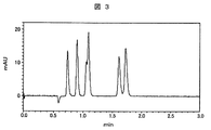
- FIG. 2 and 3 are diagrams of chromatograms obtained by liquid chromatograph
- FIG. 2 is a chromatogram obtained by the conventional method as a comparative example
- FIG. 3 is obtained by the method of this embodiment. It is a chromatogram. The analysis conditions when these chromatograms are obtained are shown below.
- the T-joint 5 to be used has an internal volume of 2.1 ⁇ L
- the pipe 6 is a pipe having an inner diameter of 0.25 mm used in the conventional post-column method, and measured under the above analysis conditions, as shown in FIG. A chromatogram was obtained.
- the reaction reagent liquid sending section for sending the reaction reagent by setting the withstand pressure of the entire system including the separation column 3 and the piping to be greater than 40 MPa.
- the pressure coil 9 is connected in such a way that the pressure applied to the pressure is equal to that of the mobile phase feed pump 1 for feeding the mobile phase. Thereby, it is possible to suppress and stabilize the pulsation of the liquid transfer of the reaction reagent liquid transfer pump 8.
- the joint where the sample eluted in the separation column 3 and the reaction reagent are mixed, that is, the T joint 5 has an internal volume of 0.57 ⁇ L.
- the pipe 6 connecting the T-joint 5 and the detector 7 directly connects an inlet tube of an inner diameter of 0.1 mm with an inner diameter of 0.13 mm or less in order to minimize the internal volume. It is desirable that the detector 7 can collect data at a speed of 50 ms or less and a response speed of 50 ms or less, with a low capacity flow cell, and a detection collection interval of 200 ms or less.
- the rising of the detection peak of the target component is sharpened, the spread can be suppressed, and the degree of separation can be improved.
- the detection peak of the chromatogram is prevented from becoming broad by using a T joint having an internal volume of 1 ⁇ L and a pipe having an inner diameter of 0.13 mm or less in the liquid chromatograph of the post column method according to this embodiment. And, a drop in sensitivity can be prevented.
- FIG. 4 is a diagram of a baseline chromatogram when the pressure applied to the reaction reagent delivery pump 8 is changed.
- the pressure applied to the reaction reagent feed pump 8 was set to 34 MPa for case a, 9.4 MPa for case b, and 0 MPa for case c, and the baseline was measured. Comparing the above three cases, noise is reduced when the pressure in case a is high. That is, it can be seen that the noise can be reduced as the pressure becomes closer to that of the mobile phase liquid transfer pump 1.
- the inside diameter of the pressure coil 9 is preferably 0.13 mm or less. Alternatively, when the inner diameter is 0.13 mm or more, the pressure applied to the reaction reagent delivery pump 8 can be increased by increasing the length of the pressure coil 9.
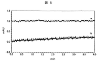
- FIG. 5 is a diagram of a baseline chromatogram when the internal volume of the T-joint 5 is changed. Since the size of the internal volume of the T joint 5 for mixing the sample eluted from the separation column 3 and the reaction reagent affects the mixing efficiency, the internal volume of the T joint 5 is desirably 1 ⁇ L or less. In the figure, the measurement was performed using 0.57 ⁇ L for the case a and 2.06 ⁇ L for the case b as the internal volume of the T joint 5. In case a, the noise of the baseline is reduced, and it can be seen that as the internal volume of the T joint 5 is smaller, the mixture of the sample eluted from the separation column 3 and the reaction solution becomes more uniform.
- FIG. 6 is a diagram of a chromatogram of an organic acid analysis to which the BTB post-column method is applied using a bromothymol blue (BTB) solution as a reaction reagent using the ultra-high performance liquid chromatograph according to the present invention shown in FIG. It is. As shown in the figure, the spread of the detection peak is suppressed, and it is possible to suppress the diffusion of the target component in the reagent mixing reaction section and measure the target component.
- BTB bromothymol blue
- a method which enables reaction of bromothymol blue solution by BTB post column method using a reverse phase mode separation column having hydrophilicity. . Since this analysis is performed using an ultra-high-speed liquid chromatograph in which the pressure resistance of the mobile phase liquid transfer pump 1 is greater than 40 MPa using a small separation column in which the particle diameter of the column packing is 2 ⁇ m, the mobile phase line Compared with the analysis of organic acid using BTB post column method, the separation column using the conventional ion exclusion mode and the ion exchange mode packing agent becomes faster without increasing the flow rate and lowering the separation performance. The measurement time can be shortened to about one-half. In addition, since the amount of use of the mobile phase and the reagent is reduced, there is an effect that these can be saved.
- FIG. 8 shows a second embodiment of the present invention, and is another configuration diagram of a high performance liquid chromatograph using a post column method.
- the high-performance liquid chromatograph includes a mobile phase feed pump 1, an injector 2 for injecting a sample, a separation column 3 for separating a sample, a column oven 4 for keeping the separation column 3 at a constant temperature, and a sample eluted from the separation column 3 T joint 5 with a three-way joint structure for mixing reagents, piping 6 flowing while the sample eluted from separation column 3 and reaction reagents are mixed, detector 7 for detecting a target component in the sample, and delivery of reaction reagents
- the reaction reagent delivery pump 8 is provided.
- the sample is injected from the injector 2, passes through the separation column 3 by the mobile phase fed from the mobile phase feed pump 1, and is separated.
- the separated sample is mixed with the reaction reagent fed from the reaction reagent feed pump 8 at the T joint 5 and passes through the pipe 10 while being reacted and detected by the detector 7.
- the internal volume of the T joint 5 is 0.57 ⁇ L which is less than 1 ⁇ L as in the first embodiment
- the pipe connecting the T joint 5 and the detector 7 is the first embodiment.
- a pipe 10 with an inner diameter of 0.1 mm and a length of 1 m is used. As it has a length of 1 m, when it is stored in the device, it is made compact, for example, in a coil shape as shown in the figure. By lengthening the length of the pipe 10, the pressure of the liquid transfer from the reaction reagent transfer pump 8 can be increased.
- This pipe has a pressurizing function similar to that of the pressurizing coil 9 in the first embodiment, and the length of the pipe 10 is preferably a pressure similar to that applied to the mobile phase liquid feeding pump 1 to the T joint 5
- FIG. 9 is a diagram of a chromatogram in which relative fluorescence intensity was measured for a relatively long time using the ultra-high performance liquid chromatograph shown in FIG. 8, wherein an orthophthalaldehyde (OPA) solution is used as a reaction reagent, amino acids, etc.
- OPA orthophthalaldehyde
- An example of the chromatogram which applied the OPA method post column method is shown for analysis of the compound which has an amino group.
- the vertical axis represents relative fluorescence intensity
- the horizontal axis represents elution time.
- the spread of the detection peak of the target component in the separation column is determined using a known calculation formula to verify the effect of the present invention.
- the spread of the detection peak of the target component in the separation column can be expressed as the dispersion ⁇ c with reference to the high performance liquid chromatography handbook Kanto branch of the Japan Society for Analytical Chemistry, Maruzen (March 2000). expressed.
- ⁇ c 0.6 ⁇ dc 2 h dp (N) 1/2 (1 + k) / 4 equation 1
- dc is the diameter of the separation column
- h the reduced theoretical height
- dp the particle diameter of the filler
- N the number of theoretical plates
- k the retention coefficient.
- dc 2 mm
- h 4
- dp 2 ⁇ m
- N 10000
- k 0, ⁇ c is 1.5 ⁇ L.
- the detection peak has already spread at the connection, and if the pipe with an inner diameter of 0.25 mm is used, the spread becomes larger as with the connection, but by using a pipe with an inner diameter of 0.13 mm or less, the influence from the connection by one digit or more Less and the spread is virtually negligible.
- the configuration of any one or the combination of them can provide an ultra-high performance liquid chromatograph which prevents the detection peak of the target component from spreading and becoming broad and prevents the decrease in sensitivity.
- FIG. 10 is a chromatogram showing differences in detected peaks due to differences in inner diameter of piping.
- the length of the pipe 10 was fixed at 1 m, and analysis was performed using four types of commercially available products whose inner diameters are 0.1 mm, 0.13 mm, 0.25 mm, and 0.3 mm.
- the T joint 5 in the figure, the reaction reagent feed pump 8, and the pipe 10 are removed, and the shortest distance between the column 3 and the detector 7 is 0.1 mm pipe with an inner diameter of 0.13 mm or less.
- the piping connected by was used, it was 0.033 minutes when analysis was conducted.
- the vertical axis in FIG. 10 is the half width (in units) of the detection peak of the chromatogram.
- the peak half value widths when the inner diameter of the pipe 10 is 0.1 mm and 0.13 mm are 0.036 minutes and 0.037 minutes, and when the inner diameter is 0.25 mm or 0.3 mm, 0.047 minutes or 0.050 Much less than a minute.
- the spread in the pipe is proportional to the square of the inner diameter of the pipe, as shown by the equation (3) above.
- the spread of the pipe having an inner diameter of 0.1 mm is 1, it becomes 1.7, 6.3, and 9.0 for 0.13 mm, 0.25 mm, and 0.3 mm, respectively, which matches the present data.
- the peak half value width when the inner diameter of the pipe 10 is 0.1 mm and 0.13 mm is a value close to that in the example shown in FIG. 1, and if the inner diameter of the pipe 10 is 0.13 mm or less, It can be seen that it is possible to suppress the spread of the detection peak of the gram and prevent it from becoming broad.
- the present invention can be applied to a liquid chromatograph which can prevent the detection peak of a chromatogram from becoming broad and can be used in a post-column method in which a decrease in sensitivity is prevented.
Landscapes
- Physics & Mathematics (AREA)
- Health & Medical Sciences (AREA)
- Life Sciences & Earth Sciences (AREA)
- Chemical & Material Sciences (AREA)
- Analytical Chemistry (AREA)
- Biochemistry (AREA)
- General Health & Medical Sciences (AREA)
- General Physics & Mathematics (AREA)
- Immunology (AREA)
- Pathology (AREA)
- Treatment Of Liquids With Adsorbents In General (AREA)
Abstract
Description
移動相流量:0.4mL/min
カラム温度:25℃
注入量:1μL
反応試薬:ブロモチモールブルー(BTB)溶液
反応試薬流量:0.5mL/min
検出器:可視光検出器(検出波長440nm)
図7に示した従来の液体クロマトグラフを用いた場合、反応試薬を送液する反応試薬送液ポンプ8にかかる圧力は3MPa以下であり、分離カラム3から溶出された試料と反応試薬とが混合するTジョイント5は内部ボリュームが2.1μLのものを用い、配管6は従来のポストカラム法で用いられている内径0.25mmの配管を使用し、上記分析条件で測定し、図2に示すクロマトグラムを得た。
充填剤:粒子径2μm シリカODS(オクシデンタルシリル基で表面が修飾された化学結合型多孔性球状シリカゲル充填剤)
移動相:20mモル/L りん酸緩衝液、ヘキサンスルホン酸ナトリウム/アセトニトリル=92/8(モル比)
移動相流量:0.4mL/min
カラム温度:25℃
注入量:1μL
反応試薬:オルトフタルアルデヒド(OPA)溶液
反応試薬流量:0.4mL/min
検出器:蛍光検出器(励起波長345nm、蛍光波長450nm)
このように、OPA法ポストカラム法においても、低容量のジョイントと内径0.13mm以下の配管を用いる本発明の構成を採用することにより、クロマトグラムの目的成分の検出ピークの広がりを抑えることができる。
σc=0.6πdc2 hdp(N)1/2(1+k)/4 …数1
但し、dcは分離カラムの直径、hは換算理論高さ、dpは充填剤の粒子径、Nは理論段数、kは保持係数である。dc=2mm、h=4、dp=2μm、N=10000、k=0とすると、σcは1.5μLとなる。
((1+a)σc)2 =σc2 +σex2 …数2
目的成分の検出ピークの広がりを20%まで許容すると、a=0.2として、σex=1μLとなる。さらに、試薬混合反応部と検出器とを接続する配管が設けられており、この配管の内径は0.13mm以下である。配管内での試料の広がり(σp)は、日本国特許出願公開公報、特開2002-243715号公報の記載によれば、次式で表される。
σp2 =r4 vLp/24Dm …数3
但しrは配管内径の半径、vは流速、Lpは配管の長さ、Dmは溶質の拡散係数である。v=1.2ml/min、Lp=100cm、
Dm=1.2×10⁻⁹ (m2/s)として、一般に高速液体クロマトグラフ用に販売されている内径0.25mmと0.13mmの配管で比較すると、内径0.25mmでは0.53μL、内径0.13mmでは0.04μLとなる。接続部において既に検出ピークが広がっており、内径0.25mmの配管を用いれば接続部と同様に広がりが大きくなるが、内径0.13mm以下の配管を用いることにより接続部より1桁以上影響が少なくなり、広がりが事実上無視できる。これらのいずれかまたは組み合わせの構成により、目的成分の検出ピークが広がってブロードになるのを防止し、かつ、感度の低下を防止した超高速液体クロマトグラフを提供することができる。
2 インジェクタ
3 分離カラム
4 カラムオーブン
5 Tジョイント
6 配管
7 検出器
8 反応試薬送液ポンプ
9 加圧コイル
10 配管
Claims (16)
- 分離カラムと、
移動相を該分離カラムに送液する移動相送液部と、
前記分離カラム通過後の液体に対して反応試薬を送液する反応試薬送液部と、
前記分離カラムから通過後の液体と前記反応試薬を混合するジョイント部と、
ジョイント部内の試料中の成分を検出する検出部とを備えた液体クロマトグラフであって、
前記移動相送液部の耐圧が40MPaより大きく、前記分離カラムの充填剤の粒子径が3μmより小さく、
前記反応試薬送液部と前記ジョイント部の間に、該反応試薬送液部にかかる圧力を上げる加圧部が接続され、
前記ジョイント部の容積は1μL以下であることを特徴とする液体クロマトグラフ。 - 分離カラムと、
移動相を分離カラムに送液する移動相送液部と、
前記分離カラム通過後の液体に対して反応試薬を送液する反応試薬送液部と、
前記分離カラム通過後の液体と前記反応試薬を混合するジョイント部と、
ジョイント部内の試料中の成分を検出する検出部とを備えた液体クロマトグラフであって、
前記移動相送液部の耐圧が40MPaより大きく、前記分離カラムの充填剤の粒子径が3μmより小さく、
前記反応試薬送液部と前記ジョイント部の間には、該反応試薬送液部にかかる圧力を上げる加圧部が接続され、
前記ジョイント部と前記検出部とを接続する接続配管が設けられており、該接続配管の内径が0.13mm以下であることを特徴とする液体クロマトグラフ。 - 前記加圧部は、コイル状のものであることを特徴とする請求項1または2に記載の液体クロマトグラフ。
- 前記加圧部は、内径が0.13mm以下の配管であることを特徴とする請求項1から3のいずれか1項に記載の液体クロマトグラフ。
- 前記加圧部は、前記反応試薬送液部にかかる圧力を前記移動相送液部にかかる圧力とほぼ同じ圧力まで上げることを特徴とする請求項1から4のいずれか1項に記載の液体クロマトグラフ。
- 前記ジョイント部と前記検出部とを接続する接続配管が設けられており、該接続配管の内径が0.13mm以下であることを特徴とする請求項1に記載の液体クロマトグラフ。
- 前記ジョイント部の容積は1μL以下であることを特徴とする請求項2に記載の液体クロマトグラフ。
- 前記反応試薬としてブロモチモールブルー溶液を用いたことを特徴とする請求項1から7のいずれか1項に記載の液体クロマトグラフ。
- 前記反応試薬としてオルトフタルアルデヒド溶液を用いたことを特徴とする請求項1から7のいずれか1項に記載の液体クロマトグラフ。
- 前記分離カラムは、親水性を備えた逆相モードのカラムであることを特徴とする請求項1から9のいずれか1項に記載の液体クロマトグラフ。
分離カラムと、
該分離カラムに移動相を送液する移動相送液部と、
前記分離カラム通過後の液体に対して反応試薬を送液する反応試薬送液部と、
前記分離カラム通過後の液体と前記反応試薬を混合するジョイント部と、
前記ジョイント部内の試料を検出する検出部とを備えた液体クロマトグラフであって、
前記移動相送液部の耐圧が40MPaより大きく、前記分離カラムの充填剤の粒子径が3μmより小さく、
前記ジョイント部の容積は1μL以下であることを特徴とする液体クロマトグラフ。 - 試料を分離する分離カラムと、
移動相を前記分離カラムに送液する移動相送液部と、
前記移動相に試料を注入するインジェクタと、
前記
前記分離カラム通過後の前記移動相に反応試薬を送液する反応試薬送液部と、
前記分離カラム通過後の前記移動相と前記反応試薬とが混合するジョイント部と、
前記試料が前記反応試薬と反応して通過する配管と、
前記反応試薬と反応した前記試料を検出する検出器とを備えた液体クロマトグラフであって、
前記反応試薬送液部から送液される反応試薬の圧力を前記移動相の圧力まで高めるように前記検出器の上流側の配管を長くしたことを特徴とする液体クロマトグラフ。 - 試料を分離する分離カラムと、
前記分離カラムに移動相を送液する移動相送液部と、
前記移動相に試料を注入するインジェクタと、
前記
前記分離カラム通過後の前記移動相に反応試薬を送液する反応試薬送液部と、
前記分離カラム通過後の前記移動相と前記反応試薬とが混合するジョイント部と、
前記試料が前記反応試薬と反応して通過する配管と、
前記反応試薬と反応した前記試料を検出する検出器とを備えた液体クロマトグラフであって、
前記反応試薬送液部と前記ジョイント部との間に、前記反応試薬送液部から送液される反応試薬の圧力を前記移動相の圧力まで高める加圧コイルを設けたことを特徴とする液体クロマトグラフ。 - 移動相を送液する移動相送液部と、
前記移動相に試料を注入するインジェクタと、
前記試料を分離する分離カラムと、
前記分離カラム通過後の前記移動相に反応試薬を送液する反応試薬送液部と、
前記分離カラム通過後の前記移動相と前記反応試薬とが混合するジョイント部と、
前記試料が前記反応試薬と反応して通過する配管と、
前記反応試薬と反応した前記試料を検出する検出器とを備えた液体クロマトグラフであって、
前記ジョイント部と前記検出器との間の前記配管の長さを、前記反応試薬送液部から送液される反応試薬の圧力を前記移動相の圧力まで高めるように長くしたことを特徴とする液体クロマトグラフ。 - 移動相を送液する移動相送液部と、
分離カラムと、
前記分離カラム通過後の液体に対して反応試薬を送液する反応試薬送液部と、
前記分離カラムから溶出された液体と前記反応試薬が混ざるジョイント部と、
検出部とを備えた液体クロマトグラフを用いた分析方法であって、
前記移動相送液部の耐圧が40MPaより大きく、前記分離カラムの充填剤の粒子径が3μmより小さく、前記ジョイント部の容積は1μL以下にして、反応試薬送液部にかかる圧力を上げることを特徴とする分析方法。 - 移動相を送液する移動相送液部と、
分離カラムと、
前記分離カラム通過後の液体に対して反応試薬を送液する反応試薬送液部と、
前記分離カラムから溶出された液体と前記反応試薬が混ざるジョイント部と、
検出部とを備えた液体クロマトグラフを用いた分析方法であって、
前記移動相送液部の耐圧が40MPaより大きく、前記分離カラムの充填剤の粒子径が3μmより小さく、前記ジョイント部と前記検出部とを接続する接続配管の内径を0.13mm以下にして、反応試薬送液部にかかる圧力を上げることを特徴とする分析方法。 - 前記反応試薬送液部にかかる圧力を前記移動相送液部にかかる圧力とほぼ同じ圧力まで上げることを特徴とする請求項11または12に記載の分析方法。
Priority Applications (2)
| Application Number | Priority Date | Filing Date | Title |
|---|---|---|---|
| JP2011502650A JPWO2010100914A1 (ja) | 2009-03-04 | 2010-03-03 | 液体クロマトグラフ及び分析方法 |
| US13/202,710 US20120058568A1 (en) | 2009-03-04 | 2010-03-03 | Liquid chromatograph and analysis method |
Applications Claiming Priority (4)
| Application Number | Priority Date | Filing Date | Title |
|---|---|---|---|
| JP2009-050074 | 2009-03-04 | ||
| JP2009050074 | 2009-03-04 | ||
| JPPCT/JP2009/006210 | 2009-11-19 | ||
| JP2009006210 | 2009-11-19 |
Publications (1)
| Publication Number | Publication Date |
|---|---|
| WO2010100914A1 true WO2010100914A1 (ja) | 2010-09-10 |
Family
ID=42709480
Family Applications (1)
| Application Number | Title | Priority Date | Filing Date |
|---|---|---|---|
| PCT/JP2010/001453 Ceased WO2010100914A1 (ja) | 2009-03-04 | 2010-03-03 | 液体クロマトグラフ及び分析方法 |
Country Status (3)
| Country | Link |
|---|---|
| US (1) | US20120058568A1 (ja) |
| JP (1) | JPWO2010100914A1 (ja) |
| WO (1) | WO2010100914A1 (ja) |
Cited By (4)
| Publication number | Priority date | Publication date | Assignee | Title |
|---|---|---|---|---|
| JP2015513076A (ja) * | 2012-02-14 | 2015-04-30 | ワイアット テクノロジー コーポレイションWyatt Tecknology Corporation | 検出器間の帯域拡張の制御 |
| CN107870219A (zh) * | 2016-09-26 | 2018-04-03 | 中国科学院大连化学物理研究所 | 一种小型化学衍生器 |
| JP2021049503A (ja) * | 2019-09-25 | 2021-04-01 | 株式会社日立ハイテクサイエンス | 液体クロマトグラフ、分離カラム、および分離カラムの充填剤 |
| WO2021132178A1 (ja) * | 2019-12-26 | 2021-07-01 | 株式会社Tasプロジェクト | 生体試料中に存在する低分子物質の抽出方法 |
Families Citing this family (3)
| Publication number | Priority date | Publication date | Assignee | Title |
|---|---|---|---|---|
| CN103176910B (zh) * | 2011-12-26 | 2015-10-14 | 群联电子股份有限公司 | 用于非易失性存储器的数据合并方法、控制器与储存装置 |
| US10617991B2 (en) * | 2015-10-26 | 2020-04-14 | Waters Technologies Corporation | Low dispersion gas-liquid separator |
| US11162922B2 (en) * | 2018-08-03 | 2021-11-02 | Shimadzu Corporation | Liquid chromatograph device |
Citations (3)
| Publication number | Priority date | Publication date | Assignee | Title |
|---|---|---|---|---|
| JPS56148057A (en) * | 1980-04-21 | 1981-11-17 | Showa Denko Kk | Acid material analyzer by high speed liquid chromatography |
| JPH0650953A (ja) * | 1992-07-29 | 1994-02-25 | Shimadzu Corp | グルタチオン分析方法 |
| JP2008051689A (ja) * | 2006-08-25 | 2008-03-06 | Tomoe Seisakusho:Kk | 液体クロマトグラフィー用耐圧クロマト管 |
Family Cites Families (6)
| Publication number | Priority date | Publication date | Assignee | Title |
|---|---|---|---|---|
| US4377482A (en) * | 1978-04-28 | 1983-03-22 | Salk Institute For Biological Studies | Mobile phase for liquid chromatography |
| JPH05142223A (ja) * | 1991-11-18 | 1993-06-08 | Hitachi Ltd | アミノ酸とノルロイシンの同時分離法 |
| JP3346965B2 (ja) * | 1995-09-14 | 2002-11-18 | 株式会社日立製作所 | アミノ酸分析装置 |
| JP4110083B2 (ja) * | 2003-12-05 | 2008-07-02 | 株式会社日立ハイテクノロジーズ | 液体クロマトグラフ |
| US7144502B2 (en) * | 2004-06-04 | 2006-12-05 | Johnson & Johnson | Chromatography system with gradient storage and method for operating the same |
| JP4547327B2 (ja) * | 2005-12-05 | 2010-09-22 | 株式会社日立ハイテクノロジーズ | 分析方法 |
-
2010
- 2010-03-03 WO PCT/JP2010/001453 patent/WO2010100914A1/ja not_active Ceased
- 2010-03-03 US US13/202,710 patent/US20120058568A1/en not_active Abandoned
- 2010-03-03 JP JP2011502650A patent/JPWO2010100914A1/ja not_active Ceased
Patent Citations (3)
| Publication number | Priority date | Publication date | Assignee | Title |
|---|---|---|---|---|
| JPS56148057A (en) * | 1980-04-21 | 1981-11-17 | Showa Denko Kk | Acid material analyzer by high speed liquid chromatography |
| JPH0650953A (ja) * | 1992-07-29 | 1994-02-25 | Shimadzu Corp | グルタチオン分析方法 |
| JP2008051689A (ja) * | 2006-08-25 | 2008-03-06 | Tomoe Seisakusho:Kk | 液体クロマトグラフィー用耐圧クロマト管 |
Non-Patent Citations (4)
| Title |
|---|
| HIROSHI NAKAMURA, EKIKURO TORANOMAKI, 30 November 2003 (2003-11-30), pages 103 - 104 * |
| HIROSHI NAKAMURA, EKIKURO TORANOMAKI, vol. 85, 1 December 2005 (2005-12-01), pages 13 - 14 * |
| LEE-SUN NEW ET AL.: "Pharmacokinetic study of intraperitoneally administered troglitazone in mice using ultra-performance liquid chromatography/tandem mass spectrometry", RAPID COMMUNICATIONS IN MASS SPECTROMETRY, vol. 21, no. 6, 2007, pages 982 - 988 * |
| MASAO BONOSHITA ET AL.: "Jisedai no HPLC-Cho Kosoku Ekitai Chromatography System- o Mochiita Iyakuhin Seibun no Kosoku Bunri", CHROMATOGRAPHY, vol. 27, no. 3, 2006, pages 131 - 134 * |
Cited By (12)
| Publication number | Priority date | Publication date | Assignee | Title |
|---|---|---|---|---|
| JP2015513076A (ja) * | 2012-02-14 | 2015-04-30 | ワイアット テクノロジー コーポレイションWyatt Tecknology Corporation | 検出器間の帯域拡張の制御 |
| CN107870219A (zh) * | 2016-09-26 | 2018-04-03 | 中国科学院大连化学物理研究所 | 一种小型化学衍生器 |
| JP2021049503A (ja) * | 2019-09-25 | 2021-04-01 | 株式会社日立ハイテクサイエンス | 液体クロマトグラフ、分離カラム、および分離カラムの充填剤 |
| JP7346201B2 (ja) | 2019-09-25 | 2023-09-19 | 株式会社日立ハイテクサイエンス | アミノ酸の検出方法 |
| JP2023158101A (ja) * | 2019-09-25 | 2023-10-26 | 株式会社日立ハイテクサイエンス | アミノ酸の検出方法、およびクロマトグラフ |
| JP7547586B2 (ja) | 2019-09-25 | 2024-09-09 | 株式会社日立ハイテクサイエンス | アミノ酸の検出方法、およびクロマトグラフ |
| WO2021132178A1 (ja) * | 2019-12-26 | 2021-07-01 | 株式会社Tasプロジェクト | 生体試料中に存在する低分子物質の抽出方法 |
| JPWO2021132178A1 (ja) * | 2019-12-26 | 2021-07-01 | ||
| CN114868016A (zh) * | 2019-12-26 | 2022-08-05 | Tas工程有限公司 | 在生物体试样中存在的低分子物质的提取方法 |
| CN114868016B (zh) * | 2019-12-26 | 2023-11-28 | Tas工程有限公司 | 在生物体试样中存在的低分子物质的提取方法 |
| JP7541303B2 (ja) | 2019-12-26 | 2024-08-28 | 株式会社Tasプロジェクト | 生体試料中に存在する低分子物質の抽出方法 |
| US12330139B2 (en) | 2019-12-26 | 2025-06-17 | TAS Project Co. Ltd | Method for extracting low-molecular-weight substance existing in biological sample |
Also Published As
| Publication number | Publication date |
|---|---|
| JPWO2010100914A1 (ja) | 2012-09-06 |
| US20120058568A1 (en) | 2012-03-08 |
Similar Documents
| Publication | Publication Date | Title |
|---|---|---|
| WO2010100914A1 (ja) | 液体クロマトグラフ及び分析方法 | |
| CN106610405B (zh) | 人尿液中儿茶酚胺类物质和其甲氧基代谢物含量的检测方法 | |
| CN102539564B (zh) | 奥硝唑注射液杂质的检测方法及含量测定方法 | |
| Nishi et al. | New Trend in the LC Separation Analysis of Pharmaceuticals–High Performance Separation by Ultra High-performance Liquid Chromatography (UHPLC) with Core-shell Particle C18 Columns– | |
| Patil et al. | A stability-indicating LC method for the simultaneous determination of telmisartan and ramipril in dosage form | |
| US7112277B2 (en) | Methods and systems for separating constituents of a highly aqueous fluid | |
| CN111323527B (zh) | 一种用复合二维液相色谱同时测定多种精神药物的方法 | |
| CN111060621B (zh) | 一种注射用头孢哌酮钠舒巴坦钠有关物质的检测方法 | |
| CN108241032B (zh) | 一种奈达铂的分析方法 | |
| Wang et al. | Quasi-solid hydrogel electrolyte/nitrogen dot-based electrochemiluminescence sensor for enrofloxacin detection in milk | |
| Hetzel et al. | Characterization of the efficiency of microbore liquid chromatography columns by van Deemter and kinetic plot analysis | |
| Zhang et al. | Preparation of a monolithic column with a mixed‐mode stationary phase of reversed‐phase/hydrophilic interaction for capillary liquid chromatography | |
| Han et al. | Analysis of some β-lactam antibiotics using ionic liquids as mobile phase additives by RP-HPLC | |
| CN112684026B (zh) | 一种奥希替尼中间体纯度的检测方法 | |
| CN103293236A (zh) | 一种测定丙胺酰谷氨酰胺含量的方法 | |
| CN103713064B (zh) | 一种用高效液相色谱法测定碱式依卡倍特铋有关物质的方法 | |
| CN113419004B (zh) | 3-氨基-4-甲基苯甲酸甲酯中杂质的检测方法 | |
| Goel et al. | Facile validated HPLC method using photodiode array detector for the combined analysis of etodolac and 5-FU in bulk and tablet dosage form | |
| Pereira | An overview of core enhanced technology for fast, high efficiency HPLC | |
| Ferrone et al. | Meropenem and ciprofloxacin in complicated gastric surgery for cancer patients: A simple SPE–UHPLC–PDA method for their determination in human plasma | |
| CN111323492A (zh) | 一种复合色谱柱以及一种二维液相色谱系统 | |
| CN112798728A (zh) | 一种分离瑞巴派特与间氯瑞巴派特的色谱分析方法 | |
| Nazeerunnisa et al. | Development and validation of a stability-indicating RP-HPLC method for determination of darifenacin hydrobromide in bulk drugs | |
| CN112083106B (zh) | 一种布洛芬中3-氯-2,2-二甲基-1-丙醇的检测方法 | |
| CN115932094B (zh) | 一种利丙双卡因乳膏中杂质的检测方法 |
Legal Events
| Date | Code | Title | Description |
|---|---|---|---|
| 121 | Ep: the epo has been informed by wipo that ep was designated in this application |
Ref document number: 10748513 Country of ref document: EP Kind code of ref document: A1 |
|
| WWE | Wipo information: entry into national phase |
Ref document number: 2011502650 Country of ref document: JP |
|
| WWE | Wipo information: entry into national phase |
Ref document number: 13202710 Country of ref document: US |
|
| NENP | Non-entry into the national phase |
Ref country code: DE |
|
| 122 | Ep: pct application non-entry in european phase |
Ref document number: 10748513 Country of ref document: EP Kind code of ref document: A1 |