WO2010100776A1 - 架線レス交通車両の充電方法及び充電システム - Google Patents
架線レス交通車両の充電方法及び充電システム Download PDFInfo
- Publication number
- WO2010100776A1 WO2010100776A1 PCT/JP2009/066218 JP2009066218W WO2010100776A1 WO 2010100776 A1 WO2010100776 A1 WO 2010100776A1 JP 2009066218 W JP2009066218 W JP 2009066218W WO 2010100776 A1 WO2010100776 A1 WO 2010100776A1
- Authority
- WO
- WIPO (PCT)
- Prior art keywords
- storage device
- power storage
- voltage
- vehicle
- value
- Prior art date
- Legal status (The legal status is an assumption and is not a legal conclusion. Google has not performed a legal analysis and makes no representation as to the accuracy of the status listed.)
- Ceased
Links
Images



Classifications
-
- B—PERFORMING OPERATIONS; TRANSPORTING
- B60—VEHICLES IN GENERAL
- B60L—PROPULSION OF ELECTRICALLY-PROPELLED VEHICLES; SUPPLYING ELECTRIC POWER FOR AUXILIARY EQUIPMENT OF ELECTRICALLY-PROPELLED VEHICLES; ELECTRODYNAMIC BRAKE SYSTEMS FOR VEHICLES IN GENERAL; MAGNETIC SUSPENSION OR LEVITATION FOR VEHICLES; MONITORING OPERATING VARIABLES OF ELECTRICALLY-PROPELLED VEHICLES; ELECTRIC SAFETY DEVICES FOR ELECTRICALLY-PROPELLED VEHICLES
- B60L53/00—Methods of charging batteries, specially adapted for electric vehicles; Charging stations or on-board charging equipment therefor; Exchange of energy storage elements in electric vehicles
- B60L53/10—Methods of charging batteries, specially adapted for electric vehicles; Charging stations or on-board charging equipment therefor; Exchange of energy storage elements in electric vehicles characterised by the energy transfer between the charging station and the vehicle
- B60L53/14—Conductive energy transfer
-
- B—PERFORMING OPERATIONS; TRANSPORTING
- B60—VEHICLES IN GENERAL
- B60L—PROPULSION OF ELECTRICALLY-PROPELLED VEHICLES; SUPPLYING ELECTRIC POWER FOR AUXILIARY EQUIPMENT OF ELECTRICALLY-PROPELLED VEHICLES; ELECTRODYNAMIC BRAKE SYSTEMS FOR VEHICLES IN GENERAL; MAGNETIC SUSPENSION OR LEVITATION FOR VEHICLES; MONITORING OPERATING VARIABLES OF ELECTRICALLY-PROPELLED VEHICLES; ELECTRIC SAFETY DEVICES FOR ELECTRICALLY-PROPELLED VEHICLES
- B60L53/00—Methods of charging batteries, specially adapted for electric vehicles; Charging stations or on-board charging equipment therefor; Exchange of energy storage elements in electric vehicles
- B60L53/10—Methods of charging batteries, specially adapted for electric vehicles; Charging stations or on-board charging equipment therefor; Exchange of energy storage elements in electric vehicles characterised by the energy transfer between the charging station and the vehicle
- B60L53/14—Conductive energy transfer
- B60L53/16—Connectors, e.g. plugs or sockets, specially adapted for charging electric vehicles
-
- H—ELECTRICITY
- H01—ELECTRIC ELEMENTS
- H01M—PROCESSES OR MEANS, e.g. BATTERIES, FOR THE DIRECT CONVERSION OF CHEMICAL ENERGY INTO ELECTRICAL ENERGY
- H01M10/00—Secondary cells; Manufacture thereof
- H01M10/42—Methods or arrangements for servicing or maintenance of secondary cells or secondary half-cells
- H01M10/44—Methods for charging or discharging
-
- H—ELECTRICITY
- H02—GENERATION; CONVERSION OR DISTRIBUTION OF ELECTRIC POWER
- H02J—ELECTRIC POWER NETWORKS; CIRCUIT ARRANGEMENTS OR SYSTEMS FOR SUPPLYING OR DISTRIBUTING ELECTRIC POWER; SYSTEMS FOR STORING ELECTRIC ENERGY
- H02J7/00—Circuit arrangements for charging or discharging batteries or for supplying loads from batteries
- H02J7/02—Circuit arrangements for charging or discharging batteries or for supplying loads from batteries for charging batteries from AC mains by converters
- H02J7/04—Regulation of charging current or voltage
-
- H—ELECTRICITY
- H02—GENERATION; CONVERSION OR DISTRIBUTION OF ELECTRIC POWER
- H02J—ELECTRIC POWER NETWORKS; CIRCUIT ARRANGEMENTS OR SYSTEMS FOR SUPPLYING OR DISTRIBUTING ELECTRIC POWER; SYSTEMS FOR STORING ELECTRIC ENERGY
- H02J7/00—Circuit arrangements for charging or discharging batteries or for supplying loads from batteries
- H02J7/90—Regulation of charging or discharging current or voltage
- H02J7/96—Regulation of charging or discharging current or voltage in response to battery voltage
-
- Y—GENERAL TAGGING OF NEW TECHNOLOGICAL DEVELOPMENTS; GENERAL TAGGING OF CROSS-SECTIONAL TECHNOLOGIES SPANNING OVER SEVERAL SECTIONS OF THE IPC; TECHNICAL SUBJECTS COVERED BY FORMER USPC CROSS-REFERENCE ART COLLECTIONS [XRACs] AND DIGESTS
- Y02—TECHNOLOGIES OR APPLICATIONS FOR MITIGATION OR ADAPTATION AGAINST CLIMATE CHANGE
- Y02E—REDUCTION OF GREENHOUSE GAS [GHG] EMISSIONS, RELATED TO ENERGY GENERATION, TRANSMISSION OR DISTRIBUTION
- Y02E60/00—Enabling technologies; Technologies with a potential or indirect contribution to GHG emissions mitigation
- Y02E60/10—Energy storage using batteries
-
- Y—GENERAL TAGGING OF NEW TECHNOLOGICAL DEVELOPMENTS; GENERAL TAGGING OF CROSS-SECTIONAL TECHNOLOGIES SPANNING OVER SEVERAL SECTIONS OF THE IPC; TECHNICAL SUBJECTS COVERED BY FORMER USPC CROSS-REFERENCE ART COLLECTIONS [XRACs] AND DIGESTS
- Y02—TECHNOLOGIES OR APPLICATIONS FOR MITIGATION OR ADAPTATION AGAINST CLIMATE CHANGE
- Y02T—CLIMATE CHANGE MITIGATION TECHNOLOGIES RELATED TO TRANSPORTATION
- Y02T10/00—Road transport of goods or passengers
- Y02T10/60—Other road transportation technologies with climate change mitigation effect
- Y02T10/70—Energy storage systems for electromobility, e.g. batteries
-
- Y—GENERAL TAGGING OF NEW TECHNOLOGICAL DEVELOPMENTS; GENERAL TAGGING OF CROSS-SECTIONAL TECHNOLOGIES SPANNING OVER SEVERAL SECTIONS OF THE IPC; TECHNICAL SUBJECTS COVERED BY FORMER USPC CROSS-REFERENCE ART COLLECTIONS [XRACs] AND DIGESTS
- Y02—TECHNOLOGIES OR APPLICATIONS FOR MITIGATION OR ADAPTATION AGAINST CLIMATE CHANGE
- Y02T—CLIMATE CHANGE MITIGATION TECHNOLOGIES RELATED TO TRANSPORTATION
- Y02T10/00—Road transport of goods or passengers
- Y02T10/60—Other road transportation technologies with climate change mitigation effect
- Y02T10/7072—Electromobility specific charging systems or methods for batteries, ultracapacitors, supercapacitors or double-layer capacitors
-
- Y—GENERAL TAGGING OF NEW TECHNOLOGICAL DEVELOPMENTS; GENERAL TAGGING OF CROSS-SECTIONAL TECHNOLOGIES SPANNING OVER SEVERAL SECTIONS OF THE IPC; TECHNICAL SUBJECTS COVERED BY FORMER USPC CROSS-REFERENCE ART COLLECTIONS [XRACs] AND DIGESTS
- Y02—TECHNOLOGIES OR APPLICATIONS FOR MITIGATION OR ADAPTATION AGAINST CLIMATE CHANGE
- Y02T—CLIMATE CHANGE MITIGATION TECHNOLOGIES RELATED TO TRANSPORTATION
- Y02T90/00—Enabling technologies or technologies with a potential or indirect contribution to GHG emissions mitigation
- Y02T90/10—Technologies relating to charging of electric vehicles
- Y02T90/14—Plug-in electric vehicles
Definitions
- the present invention relates to an overhead line-less traffic system configured such that a vehicle equipped with a power storage device travels on a track, and more particularly to a charging method and a charging system for charging a power storage device in an overhead line-less traffic vehicle.
- a vehicle of such an overhead line-less transportation system includes a power storage device (for example, a battery) that stores electric power.
- a power storage device for example, a battery
- the vehicle stores power in the power storage device and travels on a set track. It is supposed to run.
- each station on the track is provided with a charging device, and when the vehicle stops at the station, the charging device supplies power to the charging device of the vehicle (for example, Patent Document 1). .
- a vehicle of an overhead line-less traffic system includes a power storage device and an in-vehicle control device that controls a charging voltage, a charging time, and the like for the power storage device.
- a power supply facility charging device
- the power supply facility is provided at a station on the track, and when the vehicle stops at the station for receiving power, the power supply facility is in accordance with a command from an in-vehicle control device installed in the vehicle. To start charging. When the power storage amount of the power storage device reaches a predetermined value, charging of the power storage device is stopped when the in-vehicle control device issues a power reception stop command.
- the maximum voltage allowable value and the minimum voltage allowable value are preset in the power storage device.
- the interlock function in the power storage device is activated, and then the power storage device is used. You will not be able to. Therefore, during operation of the vehicle, the voltage value of the power storage device needs to be maintained between the maximum voltage allowable value and the minimum voltage allowable value.
- the voltage value of the power storage device is low at the time of departure from the station, the following problem may occur. As shown in FIG. 4, when the vehicle departs from the station, the power storage device outputs a large current when the vehicle is powered, so that the voltage value V of the power storage device greatly decreases toward the minimum voltage allowable value VL. . In the example of FIG. 4, the voltage value V of the power storage device at the time of departure from the station is in a low state. Therefore, when the voltage value V of the power storage device decreases greatly when the vehicle is powered, margin VL m between the minimum allowable voltage value VL is reduced.
- the voltage value V of the power storage device becomes lower than the minimum voltage allowable value VL depending on the use situation and environment.
- the function is activated, and there is a high possibility that the power storage device cannot be used. Therefore, the power storage device must be replaced, and the power storage device cannot be used for a long time.
- the following problems may occur. For example, when a vehicle is operated from a station with a high sea level to a station with a low sea level, if the vehicle departs from a station with a high sea level, the vehicle will travel toward a level with a low sea level. Requires a lot of power. Therefore, as shown in FIG. 5, the current returned to the power storage device by the regenerative brake is also increased, so that the voltage value V of the power storage device greatly increases toward the maximum voltage allowable value VH. As shown in FIG. 5, when the voltage value V of the power storage device increases greatly when the regenerative braking is applied to the vehicle, the voltage value V of the power storage device may be larger than the maximum voltage allowable value VH.
- the interlock function is activated and the power storage device cannot be used. Therefore, the power storage device must be replaced, and the power storage device cannot be used for a long time.
- the present invention has been made in view of such circumstances, and an object of the present invention is to reduce the overhead of the power storage device by controlling the voltage value when the charging device charges the power storage device. It is providing the charging method and charging system of a traffic vehicle.
- the power storage device of the vehicle when a vehicle equipped with a power storage device stops at a station on a track, the power storage device of the vehicle is provided on the ground side.
- the charging device charges the power storage device with a voltage setting value in the vicinity of the maximum voltage allowable value of the power storage device.
- the charging device is configured such that the voltage value of the power storage device when the vehicle is powered is greater than the minimum voltage allowable value of the power storage device and the vehicle is in regenerative braking.
- the power storage device is charged with a voltage setting value such that a voltage value of the power storage device is smaller than a maximum allowable voltage value of the power storage device.
- the overhead line-less traffic charges the power storage device of the vehicle with a charging device provided on the ground side.
- the charging device includes a control unit, and the control unit controls the power storage device to be charged with a voltage setting value in the vicinity of the maximum voltage allowable value of the power storage device.
- control means is configured so that the voltage value of the power storage device when the vehicle is powered is greater than the minimum voltage allowable value of the power storage device and the vehicle is in regenerative braking. Control is performed such that the power storage device is charged with a voltage setting value such that the voltage value of the power storage device is smaller than the maximum allowable voltage value of the power storage device.
- the charging device charges the power storage device with a voltage setting value near the maximum voltage allowable value of the power storage device, so that the voltage value of the power storage device at the time of departure from the station is conventionally Higher than As a result, even when the voltage value of the power storage device greatly decreases toward the minimum voltage allowable value when the vehicle departs from the station, the voltage value of the power storage device has a sufficient margin with respect to the minimum voltage allowable value of the power storage device.
- the power storage device can be used over a longer period within the range of the allowable voltage value, and the life (lifetime) of the power storage device can be extended.
- the charging device has a voltage value of the power storage device that is larger than a minimum allowable voltage value of the power storage device when the vehicle is powered. Since the power storage device is charged with a voltage setting value such that the voltage value of the power storage device during regenerative braking is smaller than the maximum voltage allowable value of the power storage device, for example, the vehicle moves from a station with a high sea level to a station with a low sea level. Even when the voltage value of the power storage device greatly increases toward the maximum voltage allowable value when leaving the vehicle, the voltage value of the power storage device can ensure a sufficient margin with respect to the maximum voltage allowable value of the power storage device.
- the voltage value of the power storage device becomes larger than the maximum voltage allowable value depending on the use situation or environment.
- the power storage device can be used over a longer period within the allowable voltage value range, and the life of the power storage device can be extended.
- the charging device when the vehicle equipped with the power storage device stops at a station on the track, the power storage device of the vehicle is charged by the charging device provided on the ground side.
- the charging device includes a control unit, and the control unit is controlled to charge the power storage device with a voltage set value near a maximum voltage allowable value of the power storage device. Therefore, the voltage value of the power storage device at the time of departure from the station is higher than that in the past.
- the voltage value of the power storage device has a sufficient margin with respect to the minimum voltage allowable value of the power storage device. It can be ensured, and there is no possibility that the voltage value of the power storage device becomes smaller than the minimum voltage allowable value depending on the use situation or environment.
- the power storage device can be used over a longer period within the allowable voltage value range, and the life of the power storage device can be extended.
- control means is configured such that the voltage value of the power storage device during power running of the vehicle is greater than a minimum voltage allowable value of the power storage device and Control is performed so that the power storage device is charged with a voltage setting value such that the voltage value of the power storage device during regenerative braking is smaller than the maximum voltage allowable value of the power storage device. Even if the voltage value of the power storage device greatly increases toward the maximum allowable voltage when leaving for a station with a low power, the voltage value of the power storage device has a sufficient margin for the maximum allowable voltage of the power storage device.
- the voltage value of the power storage device becomes larger than the maximum voltage allowable value depending on the use situation or environment.
- the power storage device can be used over a longer period within the allowable voltage value range, and the life of the power storage device can be extended.
- FIG. 1 is a view of a vehicle of an overhead wire-less transportation system according to an embodiment of the present invention as viewed from a traveling direction.
- the vehicle 1 of the overhead line-less traffic system includes a carriage 3 for traveling on a preset track 2.
- a current collecting contact 4 for receiving electric power is provided.
- the cart 3 includes a power storage device 5 that stores the power received by the current collecting contact 4, and the vehicle 1 stores power in the power storage device 5 when it stops at a station (not shown), The vehicle travels on the set track 2.
- a maximum voltage allowable value VH and a minimum voltage allowable value VL are preset as allowable voltage values (see FIGS. 2 and 3).
- the power storage device 5 operates an interlock function (not shown) and cannot supply power. ing.
- a support frame 6 erected adjacent to the track 2 is provided on the ground side.
- the support frame 6 is provided with a power supply contact 7 at a position facing the current collecting contact 4 when the vehicle 1 stops.
- the feeding contact 7 is connected to a charging device 9 provided on the ground side by a power line 8 embedded in the ground.
- the charging device 9 includes a control unit 10, and the control unit 10 controls electric power sent from the charging device 9 to the power storage device 5.
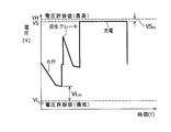
- FIG. 2 is a diagram illustrating a method for charging an overhead wire-less transportation vehicle according to the first embodiment of the present invention, in which the voltage value V and the time t of the power storage device 5 when the vehicle is running and stopped (charged). It is the figure which showed the relationship.
- the control unit 10 of the charging device 9 controls the power storage device 5 to be charged with the voltage set value VS in the vicinity of the maximum voltage allowable value VH of the power storage device 5. That is, in the present embodiment, the charging device 9 charges the power storage device 5 with the voltage setting value VS in the vicinity of the maximum voltage allowable value VH of the power storage device 5.
- the charging is usually performed by CC-CV (constant current-constant voltage) charging.
- CC-CV charging is performed by charging in CC (Constant Current) mode until the set voltage (CV value) is reached, and when reaching the set voltage, the mode shifts to CV (Constant Voltage) mode, and the current value is It is a charging method that gradually decreases.
- the voltage setting value VS of the present invention refers to this CV value.
- FIG. 2 shows an example in which the CV mode is entered immediately after charging.
- voltage setting value VS in charging device 9 is determined based on the fluctuation state of voltage value V of power storage device 5 between the stations. For example, the voltage setting value VS is set to a value that satisfies the following expression. [Equation 1] VS m ⁇ VL m
- Equation 1 VS m ⁇ VL m
- VS m is a margin between the voltage setting value VS and the maximum voltage allowable value VH
- VL m is the minimum value of the voltage value V of the power storage device 5 during vehicle operation. It is a margin between (voltage value during power running) and the minimum voltage allowable value VL.
- the charging device 9 charges the power storage device 5 with the voltage setting value VS.
- the charging device 9 is not limited to the case where the voltage setting value VS that satisfies the condition of Equation 1 is fixed and charged with a constant voltage.
- the power storage device 5 may be charged by changing the voltage setting value VS within a range that satisfies the condition of Equation 1.
- the charging device 9 charges the power storage device 5 with the voltage set value VS in the vicinity of the maximum voltage allowable value VH of the power storage device 5, as shown in FIG.
- the voltage value V of the power storage device 5 at the time of departure from the station is higher than in the conventional case (in the case of FIG. 4).
- the voltage value V of the energy storage device 5 there is no risk of less than the minimum allowable voltage value VL on usage and environment.
- the power storage device 5 can be used over a longer period within the allowable voltage value range, and the life of the power storage device 5 (lifetime) can be extended. it can.
- the energy value can be obtained by reducing the current value accordingly and reducing the power consumption.
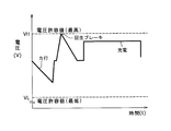
- FIG. 3 is a diagram illustrating a method for charging an overhead wire-less transportation vehicle according to the second embodiment of the present invention, in which the voltage value V and time t of the power storage device 5 when the vehicle is running and stopped (charging). It is the figure which showed the relationship.
- the control means 10 of the charging device 9 controls the power storage device 5 to be charged with the voltage set value VS. That is, in the present embodiment, the charging device 9 charges the power storage device with the voltage setting value VS.
- the voltage setting value VS is such that the voltage value V of the power storage device 5 when the vehicle 1 is in power running is greater than the minimum voltage allowable value VL of the power storage device 5 and the voltage value V of the power storage device 5 during regenerative braking of the vehicle 1. Is set to a voltage value that is smaller than the maximum voltage allowable value VH of the power storage device 5.
- voltage setting value VS in charging device 9 is determined based on the fluctuation state of voltage value V of power storage device 5 between stations.
- the voltage setting value VS has a margin VL m of 5 to 30% with respect to the minimum voltage allowable value VL when the vehicle 1 is powered, and is 5 with respect to the maximum voltage allowable value VH during regenerative braking of the vehicle 1.
- the value is set such that a margin VH m of ⁇ 30% is secured.
- control method according to the present embodiment can be combined with the method according to the first embodiment described above.
- the peak during regenerative braking is cut
- Control may be performed such that a margin VH m of 5 to 30% is secured with respect to the maximum voltage allowable value VH.
- the configuration for cutting the peak there is a configuration for cutting the peak by loading a resistor.
- the charging device 9 is configured such that the voltage value V of the power storage device 5 when the vehicle 1 is in power running is greater than the minimum voltage allowable value VL of the power storage device 5. Since the power storage device 5 is charged with the voltage set value VS such that the voltage value V of the power storage device 5 during the regenerative braking is smaller than the maximum voltage allowable value VH of the power storage device 5, for example, as shown in FIG.
- the voltage value V of the power storage device 5 greatly increases toward the maximum voltage allowable value VH when 1 departs from a station with a high sea level toward a station with a low sea level, the voltage value V of the power storage device 5 is it is possible to secure a sufficient margin VH m against 5 of the maximum allowable voltage value VH, there is no possibility that the voltage value V of the battery 5 is greater than the maximum allowable voltage value VH by the environment of use. Further, even when the voltage value V of the power storage device 5 greatly decreases toward the minimum allowable voltage value VL when the vehicle 1 departs from the station, the voltage value V of the power storage device 5 becomes the minimum allowable voltage value VL of the power storage device 5.
- a sufficient margin VL m can be secured, and there is no possibility that the voltage value V of the power storage device 5 becomes smaller than the minimum allowable voltage value VL depending on the use situation and environment.
- the power storage device 5 can be used over a longer period within the allowable voltage value range, and the life of the power storage device 5 can be extended. it can.
- the power storage device 5 of the vehicle 1 is configured to be charged in a contact manner.
- the charging device 9 is a charging power source that supplies high-frequency power, and the power storage device 5 of the vehicle 1 is contactless. You may comprise so that it may charge.
- Control means V Power storage device voltage value VL Minimum voltage allowable value VH Maximum voltage allowable value VS Voltage setting value VL m Margin between voltage value of power storage device and minimum voltage allowable value VH m Margin between voltage value of power storage device and maximum voltage allowable value VS m Between voltage setting value and maximum voltage allowable value Margin
Landscapes
- Engineering & Computer Science (AREA)
- Power Engineering (AREA)
- Transportation (AREA)
- Mechanical Engineering (AREA)
- Manufacturing & Machinery (AREA)
- Chemical & Material Sciences (AREA)
- Chemical Kinetics & Catalysis (AREA)
- Electrochemistry (AREA)
- General Chemical & Material Sciences (AREA)
- Charge And Discharge Circuits For Batteries Or The Like (AREA)
- Electric Propulsion And Braking For Vehicles (AREA)
Abstract
Description
図4に示すように、車両が駅から出発すると、車両を力行させる際に蓄電装置が大きな電流を出力するので、蓄電装置の電圧値Vが最低電圧許容値VLに向かって大きく下がることになる。図4の例では、駅を出発する時点での蓄電装置の電圧値Vが低い状態にあるので、車両を力行させる際に蓄電装置の電圧値Vが大きく下がると、蓄電装置の電圧値Vと最低電圧許容値VLとの間のマージンVLmが小さくなる。
例えば、海抜の高い駅から海抜の低い駅に向かって車両が運行される場合、車両が海抜の高い駅から出発すると、車両は海抜の低い方へ向かって走行するので、車両にブレーキをかけるために大きな力が必要となる。したがって、図5に示すように、回生ブレーキにより蓄電装置へ戻される電流も大きくなるので、蓄電装置の電圧値Vが最高電圧許容値VHに向かって大きく上がることになる。図5に示すように、車両に回生ブレーキをかける際に蓄電装置の電圧値Vが大きく上がると、蓄電装置の電圧値Vが最高電圧許容値VHより大きくなるおそれがある。
このように、車両が複数の駅間を走行する場合において蓄電装置を許容電圧値の範囲内でより長い期間にわたって使用できるようになり、蓄電装置の寿命(耐用期間)を延ばすことができる。
このように、車両が高低差のある複数の駅間を走行する場合において蓄電装置を許容電圧値の範囲内でより長い期間にわたって使用できるようになり、蓄電装置の寿命を延ばすことができる。
このように、車両が複数の駅間を走行する場合において蓄電装置を許容電圧値の範囲内でより長い期間にわたって使用できるようになり、蓄電装置の寿命を延ばすことができる。
このように、車両が高低差のある複数の駅間を走行する場合において蓄電装置を許容電圧値の範囲内でより長い期間にわたって使用できるようになり、蓄電装置の寿命を延ばすことができる。
かかる構成により、車両1が駅に停車した際には、集電接触子4と給電接触子7とが接触することにより、地上側の充電装置9から供給される電力が蓄電装置5に蓄電されることになる。
以下、本発明の第1実施形態に係る架線レス交通車両の充電方法を、図面を参照しながら説明する。図2は、本発明の第1実施形態に係る架線レス交通車両の充電方法を示した図であり、車両が走行及び停車(充電)している際の蓄電装置5の電圧値Vと時間tとの関係を示した図である。
なお、充電は、通常、CC-CV(定電流-定電圧)充電により行う。ここで、CC-CV充電とは、始めにCC(Constant Current)モードで、設定電圧(CV値)になるまで充電し、設定電圧に達したらCV(Constant Voltage)モードに移行し、電流値が徐々に小さくなっていく充電方法である。本発明の電圧設定値VSは、このCV値のことを言う。図2では、充電直後にCVモードになった例を示している。
[数1]
VSm ≦ VLm
ここで、図2に示すように、VSmは、電圧設定値VSと最高電圧許容値VHとの間のマージンであり、VLmは、車両運行時の蓄電装置5の電圧値Vの最低値(力行時の電圧値)と最低電圧許容値VLとの間のマージンである。
このように、車両1が複数の駅間を走行する場合において蓄電装置5を許容電圧値の範囲内でより長い期間にわたって使用できるようになり、蓄電装置5の寿命(耐用期間)を延ばすことができる。
また、全般に電圧が高くなるので、その分電流値が小さくなり、消費電力が減るという省エネ効果を得ることができる。
以下、本発明の第2実施形態に係る架線レス交通車両の充電方法を、図面を参照しながら説明する。図3は、本発明の第2実施形態に係る架線レス交通車両の充電方法を示した図であり、車両が走行及び停車(充電)している際の蓄電装置5の電圧値Vと時間tとの関係を示した図である。
例えば、第1実施形態に係る方法で蓄電装置5を充電しておき、回生ブレーキ時の電圧値Vが最高電圧許容値VHに近づくような場合には、回生ブレーキ時のピークをカットして、最高電圧許容値VHに対して5~30%分のマージンVHmが確保されるように制御してもよい。ここでピークをカットする構成の例としては、抵抗器を積んでピークをカットする構成がある。
また、車両1が駅から出発した際に蓄電装置5の電圧値Vが最低電圧許容値VLに向かって大きく下がった場合でも、蓄電装置5の電圧値Vが蓄電装置5の最低電圧許容値VLに対して十分なマージンVLmを確保することができ、使用状況や環境により蓄電装置5の電圧値Vが最低電圧許容値VLより小さくなるおそれがない。
このように、車両1が高低差のある複数の駅間を走行する場合において蓄電装置5を許容電圧値の範囲内でより長い期間にわたって使用できるようになり、蓄電装置5の寿命を延ばすことができる。
2 軌道
3 台車
3a 台車の側面
4 集電接触子
5 蓄電装置
6 支持フレーム
7 給電接触子
8 電力線
9 充電装置
10 制御手段
V 蓄電装置の電圧値
VL 最低電圧許容値
VH 最高電圧許容値
VS 電圧設定値
VLm 蓄電装置の電圧値と最低電圧許容値との間のマージン
VHm 蓄電装置の電圧値と最高電圧許容値との間のマージン
VSm 電圧設定値と最高電圧許容値との間のマージン
Claims (4)
- 蓄電装置を搭載した車両が軌道上の駅で停車した際に前記車両の前記蓄電装置を地上側に設けられた充電装置により充電する架線レス交通車両の充電方法において、
前記充電装置が、前記蓄電装置の最高電圧許容値近傍の電圧設定値で前記蓄電装置を充電することを特徴とする架線レス交通車両の充電方法。 - 前記充電装置が、前記車両の力行時の前記蓄電装置の電圧値が前記蓄電装置の最低電圧許容値より大きくなり且つ前記車両の回生ブレーキ時の前記蓄電装置の電圧値が前記蓄電装置の最高電圧許容値より小さくなるような電圧設定値で前記蓄電装置を充電することを特徴とする請求項1に記載の架線レス交通車両の充電方法。
- 蓄電装置を搭載した車両が軌道上の駅で停車した際に前記車両の前記蓄電装置を地上側に設けられた充電装置により充電する架線レス交通車両の充電システムにおいて、
前記充電装置が、制御手段を備えており、該制御手段が、前記蓄電装置の最高電圧許容値近傍の電圧設定値で前記蓄電装置を充電するように制御することを特徴とする架線レス交通車両の充電システム。 - 前記制御手段が、前記車両の力行時の前記蓄電装置の電圧値が前記蓄電装置の最低電圧許容値より大きくなり且つ前記車両の回生ブレーキ時の前記蓄電装置の電圧値が前記蓄電装置の最高電圧許容値より小さくなるような電圧設定値で前記蓄電装置を充電するように制御することを特徴とする請求項3に記載の架線レス交通車両の充電システム。
Priority Applications (3)
| Application Number | Priority Date | Filing Date | Title |
|---|---|---|---|
| US13/139,178 US8836271B2 (en) | 2009-03-06 | 2009-09-17 | Method and system for charging transportation vehicle without contact wire |
| CN2009801533975A CN102271955B (zh) | 2009-03-06 | 2009-09-17 | 用于对无接触线的交通工具进行充电的方法和系统 |
| SG2011043320A SG172137A1 (en) | 2009-03-06 | 2009-09-17 | Method and system for charging transportation vehicle without contact wire |
Applications Claiming Priority (2)
| Application Number | Priority Date | Filing Date | Title |
|---|---|---|---|
| JP2009-053107 | 2009-03-06 | ||
| JP2009053107A JP4576465B2 (ja) | 2009-03-06 | 2009-03-06 | 架線レス交通車両の充電方法及び充電システム |
Publications (1)
| Publication Number | Publication Date |
|---|---|
| WO2010100776A1 true WO2010100776A1 (ja) | 2010-09-10 |
Family
ID=42709351
Family Applications (1)
| Application Number | Title | Priority Date | Filing Date |
|---|---|---|---|
| PCT/JP2009/066218 Ceased WO2010100776A1 (ja) | 2009-03-06 | 2009-09-17 | 架線レス交通車両の充電方法及び充電システム |
Country Status (6)
| Country | Link |
|---|---|
| US (1) | US8836271B2 (ja) |
| JP (1) | JP4576465B2 (ja) |
| CN (1) | CN102271955B (ja) |
| SG (1) | SG172137A1 (ja) |
| TW (1) | TW201033040A (ja) |
| WO (1) | WO2010100776A1 (ja) |
Families Citing this family (7)
| Publication number | Priority date | Publication date | Assignee | Title |
|---|---|---|---|---|
| EP2571344B1 (en) * | 2010-05-19 | 2017-09-13 | Husqvarna AB | Effective charging by multiple contact points |
| US8725330B2 (en) | 2010-06-02 | 2014-05-13 | Bryan Marc Failing | Increasing vehicle security |
| US9285432B2 (en) * | 2011-07-26 | 2016-03-15 | GM Global Technology Operations LLC | Method and system for controlling a vehicle battery |
| DE112012006861B4 (de) * | 2012-08-31 | 2024-01-11 | Siemens Aktiengesellschaft | Batterieladesystem und Verfahren zum kabellosen Laden einer Batterie |
| US10027173B2 (en) * | 2014-07-17 | 2018-07-17 | Flir Systems, Inc. | Powered security camera tool-free installation |
| US10320202B2 (en) * | 2014-09-30 | 2019-06-11 | Johnson Controls Technology Company | Battery system bi-stable relay control |
| CN107323297A (zh) * | 2017-07-14 | 2017-11-07 | 尚圣杰 | 一种无限远程续航电动汽车的驮载移动刷电充电装置 |
Citations (6)
| Publication number | Priority date | Publication date | Assignee | Title |
|---|---|---|---|---|
| JP2002315216A (ja) * | 2001-04-05 | 2002-10-25 | Yamaha Motor Co Ltd | 電動ゴルフカートの急速充電装置 |
| JP2006054958A (ja) * | 2004-08-11 | 2006-02-23 | Mitsubishi Heavy Ind Ltd | 電気車両、架線レス交通システム及び架線レス交通システムの制御方法 |
| JP2006219128A (ja) * | 2003-02-14 | 2006-08-24 | Hitachi Ltd | ハイブリッド鉄道車両用二次電池装置 |
| JP2007189768A (ja) * | 2006-01-11 | 2007-07-26 | Mitsubishi Heavy Ind Ltd | 交通システム |
| JP2007202335A (ja) * | 2006-01-27 | 2007-08-09 | Mitsubishi Heavy Ind Ltd | 交通システム、車両、交通システムの充電方法及び充電管理方法 |
| JP2008141846A (ja) * | 2006-11-30 | 2008-06-19 | Mitsubishi Heavy Ind Ltd | 充電状態予測プログラム、架線レス交通システム及びその充電方法 |
Family Cites Families (16)
| Publication number | Priority date | Publication date | Assignee | Title |
|---|---|---|---|---|
| DE4243710C2 (de) * | 1992-12-23 | 1998-07-30 | Telefunken Microelectron | Ladeverfahren für Akkumulatoren und Schaltanordnung zur Durchführung des Verfahrens |
| JP3924077B2 (ja) | 1998-09-02 | 2007-06-06 | 財団法人鉄道総合技術研究所 | 電力蓄積式電動機、電力蓄積式電動機を用いた電力蓄積方法 |
| JP3890168B2 (ja) * | 1999-08-03 | 2007-03-07 | 株式会社東京アールアンドデー | 電動装置及びその電池ユニットの充放電方法 |
| JP3749143B2 (ja) * | 2001-06-14 | 2006-02-22 | 矢崎総業株式会社 | 車両用電源装置 |
| JP2003102181A (ja) * | 2001-09-25 | 2003-04-04 | Toyota Motor Corp | 電力供給システムおよび電力供給方法 |
| US20030057919A1 (en) * | 2001-09-27 | 2003-03-27 | Tai-Her Yang | Storage/discharging device charging circuit of multi-differential source |
| JP3886389B2 (ja) * | 2002-02-07 | 2007-02-28 | 株式会社リコー | 電池パック充電装置および充電方法 |
| JP3872758B2 (ja) * | 2003-01-08 | 2007-01-24 | 株式会社日立製作所 | 電源制御装置 |
| US6963186B2 (en) * | 2003-02-28 | 2005-11-08 | Raymond Hobbs | Battery charger and method of charging a battery |
| JP4678243B2 (ja) * | 2005-06-08 | 2011-04-27 | トヨタ自動車株式会社 | 電力供給システム |
| JP4577274B2 (ja) * | 2006-06-06 | 2010-11-10 | 株式会社デンソー | 車両用電源システム |
| JP5291909B2 (ja) * | 2007-09-21 | 2013-09-18 | 富士重工業株式会社 | 電気自動車の充電装置 |
| JP5134904B2 (ja) * | 2007-10-10 | 2013-01-30 | 富士重工業株式会社 | 電気自動車の充電装置 |
| US7956570B2 (en) * | 2008-01-07 | 2011-06-07 | Coulomb Technologies, Inc. | Network-controlled charging system for electric vehicles |
| JP4981973B2 (ja) * | 2008-09-02 | 2012-07-25 | 三菱重工業株式会社 | 架線レス交通システムの充電システム |
| US8054039B2 (en) * | 2008-12-19 | 2011-11-08 | GM Global Technology Operations LLC | System and method for charging a plug-in electric vehicle |
-
2009
- 2009-03-06 JP JP2009053107A patent/JP4576465B2/ja not_active Expired - Fee Related
- 2009-09-03 TW TW098129745A patent/TW201033040A/zh not_active IP Right Cessation
- 2009-09-17 CN CN2009801533975A patent/CN102271955B/zh not_active Expired - Fee Related
- 2009-09-17 WO PCT/JP2009/066218 patent/WO2010100776A1/ja not_active Ceased
- 2009-09-17 US US13/139,178 patent/US8836271B2/en active Active
- 2009-09-17 SG SG2011043320A patent/SG172137A1/en unknown
Patent Citations (6)
| Publication number | Priority date | Publication date | Assignee | Title |
|---|---|---|---|---|
| JP2002315216A (ja) * | 2001-04-05 | 2002-10-25 | Yamaha Motor Co Ltd | 電動ゴルフカートの急速充電装置 |
| JP2006219128A (ja) * | 2003-02-14 | 2006-08-24 | Hitachi Ltd | ハイブリッド鉄道車両用二次電池装置 |
| JP2006054958A (ja) * | 2004-08-11 | 2006-02-23 | Mitsubishi Heavy Ind Ltd | 電気車両、架線レス交通システム及び架線レス交通システムの制御方法 |
| JP2007189768A (ja) * | 2006-01-11 | 2007-07-26 | Mitsubishi Heavy Ind Ltd | 交通システム |
| JP2007202335A (ja) * | 2006-01-27 | 2007-08-09 | Mitsubishi Heavy Ind Ltd | 交通システム、車両、交通システムの充電方法及び充電管理方法 |
| JP2008141846A (ja) * | 2006-11-30 | 2008-06-19 | Mitsubishi Heavy Ind Ltd | 充電状態予測プログラム、架線レス交通システム及びその充電方法 |
Also Published As
| Publication number | Publication date |
|---|---|
| TWI369305B (ja) | 2012-08-01 |
| TW201033040A (en) | 2010-09-16 |
| SG172137A1 (en) | 2011-07-28 |
| CN102271955B (zh) | 2013-09-25 |
| JP4576465B2 (ja) | 2010-11-10 |
| JP2010207060A (ja) | 2010-09-16 |
| CN102271955A (zh) | 2011-12-07 |
| US20110309791A1 (en) | 2011-12-22 |
| US8836271B2 (en) | 2014-09-16 |
Similar Documents
| Publication | Publication Date | Title |
|---|---|---|
| JP4576465B2 (ja) | 架線レス交通車両の充電方法及び充電システム | |
| JP4476917B2 (ja) | バッテリ駆動の鉄道列車 | |
| JP4981973B2 (ja) | 架線レス交通システムの充電システム | |
| JPWO2015118574A1 (ja) | 列車エネルギー制御システム、地上装置、車上装置 | |
| US10363835B2 (en) | Railroad system | |
| US20140239879A1 (en) | Battery charging system | |
| JP2025116195A (ja) | ダンプトラックおよび給電システム | |
| JP2012175803A (ja) | 電力蓄積手段を備える鉄道システム | |
| KR20180092203A (ko) | 철도차량용 무선 급전전력 안정화를 위한 에너지 저장장치 | |
| CN103270662B (zh) | 电力供给装置、起重机及电力供给方法 | |
| JP2008154355A (ja) | 蓄電設備 | |
| JP6470947B2 (ja) | 駆動システム、及び気動車 | |
| WO2012176942A1 (ko) | 전력 공급 시스템 및 방법 | |
| CN103339820B (zh) | 电力供给装置以及供给电力控制方法 | |
| JP6196764B2 (ja) | 電力供給装置、電力供給方法およびプログラム | |
| JP6001350B2 (ja) | 鉄道システム | |
| JP4709654B2 (ja) | 交通システム | |
| JP2005295680A (ja) | 非接触給電装置及び非接触給電システム | |
| KR20110041881A (ko) | 비접촉 자기 유도 충전 방식의 전기자동차 전력 공급 시스템 | |
| JP4823328B2 (ja) | 温度制御方法及び温度制御装置 | |
| KR20180094645A (ko) | 전압 안정화 모듈이 구비된 철도 무선 급전장치 | |
| KR20150112061A (ko) | 양방향 무선충전 전기자동차 시스템 | |
| KR20110073105A (ko) | 비접촉 자기 유도 충전 방식의 전기자동차 전력 공급 시스템 및 방법 |
Legal Events
| Date | Code | Title | Description |
|---|---|---|---|
| WWE | Wipo information: entry into national phase |
Ref document number: 200980153397.5 Country of ref document: CN |
|
| 121 | Ep: the epo has been informed by wipo that ep was designated in this application |
Ref document number: 09841136 Country of ref document: EP Kind code of ref document: A1 |
|
| WWE | Wipo information: entry into national phase |
Ref document number: 13139178 Country of ref document: US |
|
| NENP | Non-entry into the national phase |
Ref country code: DE |
|
| 122 | Ep: pct application non-entry in european phase |
Ref document number: 09841136 Country of ref document: EP Kind code of ref document: A1 |