WO2010095419A1 - ガスクーラ - Google Patents
ガスクーラ Download PDFInfo
- Publication number
- WO2010095419A1 WO2010095419A1 PCT/JP2010/000949 JP2010000949W WO2010095419A1 WO 2010095419 A1 WO2010095419 A1 WO 2010095419A1 JP 2010000949 W JP2010000949 W JP 2010000949W WO 2010095419 A1 WO2010095419 A1 WO 2010095419A1
- Authority
- WO
- WIPO (PCT)
- Prior art keywords
- heat transfer
- heat
- tube
- gas
- gas cooler
- Prior art date
Links
Images


Classifications
-
- F—MECHANICAL ENGINEERING; LIGHTING; HEATING; WEAPONS; BLASTING
- F28—HEAT EXCHANGE IN GENERAL
- F28F—DETAILS OF HEAT-EXCHANGE AND HEAT-TRANSFER APPARATUS, OF GENERAL APPLICATION
- F28F1/00—Tubular elements; Assemblies of tubular elements
- F28F1/10—Tubular elements and assemblies thereof with means for increasing heat-transfer area, e.g. with fins, with projections, with recesses
- F28F1/12—Tubular elements and assemblies thereof with means for increasing heat-transfer area, e.g. with fins, with projections, with recesses the means being only outside the tubular element
- F28F1/24—Tubular elements and assemblies thereof with means for increasing heat-transfer area, e.g. with fins, with projections, with recesses the means being only outside the tubular element and extending transversely
- F28F1/32—Tubular elements and assemblies thereof with means for increasing heat-transfer area, e.g. with fins, with projections, with recesses the means being only outside the tubular element and extending transversely the means having portions engaging further tubular elements
-
- F—MECHANICAL ENGINEERING; LIGHTING; HEATING; WEAPONS; BLASTING
- F28—HEAT EXCHANGE IN GENERAL
- F28D—HEAT-EXCHANGE APPARATUS, NOT PROVIDED FOR IN ANOTHER SUBCLASS, IN WHICH THE HEAT-EXCHANGE MEDIA DO NOT COME INTO DIRECT CONTACT
- F28D7/00—Heat-exchange apparatus having stationary tubular conduit assemblies for both heat-exchange media, the media being in contact with different sides of a conduit wall
- F28D7/10—Heat-exchange apparatus having stationary tubular conduit assemblies for both heat-exchange media, the media being in contact with different sides of a conduit wall the conduits being arranged one within the other, e.g. concentrically
-
- F—MECHANICAL ENGINEERING; LIGHTING; HEATING; WEAPONS; BLASTING
- F28—HEAT EXCHANGE IN GENERAL
- F28D—HEAT-EXCHANGE APPARATUS, NOT PROVIDED FOR IN ANOTHER SUBCLASS, IN WHICH THE HEAT-EXCHANGE MEDIA DO NOT COME INTO DIRECT CONTACT
- F28D7/00—Heat-exchange apparatus having stationary tubular conduit assemblies for both heat-exchange media, the media being in contact with different sides of a conduit wall
- F28D7/08—Heat-exchange apparatus having stationary tubular conduit assemblies for both heat-exchange media, the media being in contact with different sides of a conduit wall the conduits being otherwise bent, e.g. in a serpentine or zig-zag
-
- F—MECHANICAL ENGINEERING; LIGHTING; HEATING; WEAPONS; BLASTING
- F28—HEAT EXCHANGE IN GENERAL
- F28D—HEAT-EXCHANGE APPARATUS, NOT PROVIDED FOR IN ANOTHER SUBCLASS, IN WHICH THE HEAT-EXCHANGE MEDIA DO NOT COME INTO DIRECT CONTACT
- F28D7/00—Heat-exchange apparatus having stationary tubular conduit assemblies for both heat-exchange media, the media being in contact with different sides of a conduit wall
- F28D7/16—Heat-exchange apparatus having stationary tubular conduit assemblies for both heat-exchange media, the media being in contact with different sides of a conduit wall the conduits being arranged in parallel spaced relation
-
- F—MECHANICAL ENGINEERING; LIGHTING; HEATING; WEAPONS; BLASTING
- F28—HEAT EXCHANGE IN GENERAL
- F28F—DETAILS OF HEAT-EXCHANGE AND HEAT-TRANSFER APPARATUS, OF GENERAL APPLICATION
- F28F1/00—Tubular elements; Assemblies of tubular elements
- F28F1/10—Tubular elements and assemblies thereof with means for increasing heat-transfer area, e.g. with fins, with projections, with recesses
Definitions
- the present invention relates to a gas cooler that cools high-temperature gas discharged from a gas compressor or the like, and more particularly, to a gas cooler that can be downsized by improving the heat transfer performance of a heat exchanger.
- a gas cooler is used to cool the gas heated to a high temperature of 100 ° C. or higher discharged from the gas compressor.
- the gas cooler includes a heat exchanger that exchanges heat between a high-temperature gas and a cooling medium.
- the model of this heat exchanger is a shell and tube system.
- a heat exchanger tube as a heat exchanger tube, a bare tube (for example, patent document 1, patent document 2) and a fin tube system are known. In the bare tube system, in order to increase the heat transfer area, it is necessary to increase the number of heat transfer tubes or to increase the length of the heat transfer tubes, which increases the size of the gas cooler.
- the fin-tube type heat exchanger only needs to change the fin pitch for the need to cool hot gas more efficiently at the same size. Since the heat transfer area can be increased, the heat transfer performance can be improved while minimizing the increase in size.
- the fin-tube heat exchanger is also used in an air conditioner (hereinafter, air conditioner).
- air conditioner air conditioner
- the outer diameter of the heat transfer tube is D O
- the arrangement pitch of the heat transfer tubes in the flow direction of the cooled gas is L1
- the arrangement pitch of the heat transfer tubes in the direction perpendicular to the flow direction of the cooled gas is L2.
- Patent Document 4 proposes that the width W of the fin be 22.2 ⁇ W ⁇ 26.2 mm.
- Patent Document 3 Patent Document 4 and the like are considered to be mainly intended for heat exchangers for air conditioning and the like, and are not targeted for a gas to be cooled exceeding 100 ° C. like that for a compressor.
- a heat exchanger for a compressor it was unknown whether it was possible to ensure a predetermined heat transfer performance.
- the present invention has been made on the basis of such technical problems as a gas cooler for a compressor, and an object thereof is to improve the heat transfer performance of a gas cooler including a fin-and-tube type heat exchanger.
- the present inventors have studied the specifications of the heat exchanger. As a result, by setting the outer diameter of the heat transfer tube to a specific range, the cooling of the gas to be cooled at about 100 to 150 ° C. At that time, it was found that a high heat transfer coefficient can be obtained while suppressing pressure loss.
- the present invention is based on this finding, and includes a heat exchanger, and heat exchange is performed between the heated gas to be cooled and the heat exchanger introduced from the outside, thereby cooling the gas to be cooled and externally.
- the heat exchanger is arranged in parallel with each other through a predetermined gap, and the plurality of heat transfer fins through which the gas to be cooled flows and the plurality of heat transfer fins pass through the gap to be cooled.
- the pitch of the heat transfer tubes in the direction orthogonal to the flow direction of the gas to be cooled is S 1 and the pitch of the heat transfer tubes in the flow direction of the gas to be cooled is S 2 , S 1 is 30 to 50 mm, S Setting 2 to 30 to 50 mm is advantageous for obtaining a high heat transfer coefficient while suppressing pressure loss.
- the filler is preferably a heat conductive adhesive.
- the outer diameter of the heat transfer tube is expanded by pushing a die into the heat transfer tube, and the tube transfer rate of the heat transfer tube is 0.3 to 1.5%.
- tube expansion rate (%) ⁇ heat-transfer tube outer diameter d TO2 after tube expansion ⁇ heat-transfer fin inner diameter d fin1 ⁇ before tube expansion / heat-transfer fin inner diameter d fin1 ⁇ 100 ⁇ ⁇ (die outer diameter d D + heat transfer tube wall before tube expansion ) Thickness ⁇ d T ) ⁇ heat transfer fin inner diameter d fin1 ⁇ before tube expansion / heat transfer fin inner diameter d fin1 ⁇ 100 before tube expansion .
- a high heat transfer coefficient can be obtained while suppressing pressure loss, so that even if the gas cooler (heat exchanger) is downsized, the high-temperature gas to be cooled can be sufficiently cooled.
- FIG. 1 shows schematic structure of the gas cooler in this Embodiment. It is sectional drawing which shows the joining method of the heat exchanger tube and heat exchanger fin by this Embodiment. It is sectional drawing which shows the part which joined the heat exchanger tube and heat-transfer fin by this Embodiment through the filler. Shows the main part of the heat exchanger, the outer diameter d 0 of the heat transfer tube 7 is a diagram showing a piping pitch S 1, S 2 of the heat transfer tube 7. The outer diameter d 0 of the heat transfer tube, the heat transfer coefficient is a graph showing the relationship between the pressure loss. A pipe pitch S 1 of the heat transfer tube, the heat transfer coefficient is a graph showing the relationship between the pressure loss.
- the pipe pitch S 2 of the heat transfer tube, the heat transfer coefficient is a graph showing the relationship between the pressure loss. It is a graph which shows the relationship between the presence or absence of a heat conductive adhesive, a heat transfer rate, and a pressure loss. It is sectional drawing which shows joining and a dimension of the heat exchanger tube and heat exchanger fin by this Embodiment. It is a graph which shows the relationship between a pipe expansion rate and a contact heat transfer rate.
- FIG. 1 is a diagram showing a schematic configuration of a gas cooler 10 in the present embodiment.
- the gas cooler 10 includes a fin-and-tube type heat exchanger 6 that cools process gas (cooled gas) supplied to a gas compressor (not shown) with cooling water (cooling medium), for example.
- the gas cooler 10 includes a gas cooler main body 1 formed in a horizontal drum shape, and a cooling water inlet 2 and a cooling water outlet 3 are provided on one end side in the longitudinal direction.
- a gas inlet 4 and a gas outlet 5 are formed in the outer peripheral surface of the gas cooler main body 1.
- a heat exchanger 6 is provided inside the gas cooler body 1.
- the heat exchanger 6 is juxtaposed along the longitudinal direction of the cooler body 1 with a predetermined gap therebetween, and a plurality of heat transfer fins 8 through which the process gas flows and the heat transfer fins 8 pass through the gap.
- a heat transfer tube 7 provided in a plurality of rows along the direction in which the cooling gas flows.
- the heat transfer tube 7 is made of SUS304, cupro-nickel alloy, titanium alloy, copper material, or the like.
- the heat transfer fin 8 is preferably aluminum (including an alloy) or copper (including an alloy). As aluminum, a pure aluminum-based 1000 series alloy (especially 1050) alloy excellent in formability and thermal conductivity is preferable.
- the heat transfer tubes 7 and the heat transfer fins 8 may be joined by brazing, but the cost and the brazing of the aluminum alloy and stainless steel are difficult, so the diameter of the heat transfer tubes 7 is expanded.
- a tube expansion method is preferred.
- FIG. 2 shows an image of the tube expansion method. After inserting the heat transfer tube 7 into the through hole of the heat transfer fin 8, the die D is pushed into the heat transfer tube 7 to increase the diameter of the heat transfer tube 7. The heat tubes 7 and the heat transfer fins 8 are joined by causing plastic deformation.
- a heat conductive adhesive As the filler 9, it is preferable to use a heat conductive adhesive.
- the heat transfer adhesive an adhesive matrix made of a thermosetting resin containing a metal filler as a heat transfer material can be used.
- the metal filler aluminum, copper, silver or the like is used. If the metal filler is contained in the range of about 30 to 50% by volume, sufficient heat conductivity is imparted between the heat transfer tubes 7 and the heat transfer fins 8.
- known substances such as epoxy resin, polyester, polyurethane, and phenol resin can be used.
- Such a heat conductive adhesive can be cured by heating in the manufacturing stage of the heat exchanger 6, or after being incorporated in the gas cooler 10 in an uncured state, by being in contact with a high-temperature gas to be cooled.
- Cooling water supplied from a cooling water inlet 2 from a cooling water supply source (not shown) is discharged from the cooling water outlet 3 after circulating through the heat exchanger 6 by flowing through the heat transfer tubes 7 in order.
- the heat-exchanged cooling water flowing through the heat transfer tube 7 has a temperature of approximately 15 to 50 ° C.
- a to-be-cooled (process) gas of about 100 to 150 ° C. supplied from the gas compressor (not shown) into the gas cooler body 1 through the gas inlet 4 passes through the heat exchanger 6, that is, the heat transfer fins 8.
- the cooled gas is supplied again to the gas compressor from the gas outlet 5 through a pipe (not shown), and the compression is repeated.
- FIG. 4 shows a main part of the heat exchanger 6, (a) is a partial front view, and (b) is a partial side view.
- the outer diameter of the heat transfer tube 7 is d 0
- the pipe pitch of the heat transfer tube 7 is S 1 (orthogonal to the flow direction of the gas to be cooled)
- S 2 the flow direction of the gas to be cooled
- the pipe pitch of the heat transfer tube 7 in the flow direction of the cooling gas in the present invention is defined as S 2 rather than S 3.
- the heat transfer tube 7 was made of SUS304, and the thickness of the heat transfer tube 7 was about 1.7 mm.
- the heat transfer fins 8 were made of 1050 alloy-based aluminum, and the plate thickness was about 0.35 mm. Moreover, the temperature of the to-be-cooled gas was about 120 ° C., and the cooling water flowing into the heat transfer tube 7 was 45 ° C.
- the pressure loss of the gas side increases by increased flow rate of the outer tube (gas side).
- the reference value of the pressure loss is about 2% of the inlet process gas pressure, and when the inlet pressure is about 1 to 5 (kg / cm 2 ), about 200 to 1000 mmAq is desirable.
- permissible pressure loss becomes less than it.
- the outer diameter d 0 of the heat transfer tube 7 is preferably 20 to 30 mm.
- a more preferable outer diameter d 0 of the heat transfer tube 7 is 23 to 27 mm.
- the pitch S 1 and the pitch S 2 are set in the range of 30 to 50 mm in consideration of the heat transfer coefficient U and the pressure loss ⁇ P.
- a preferable pitch S 1 and pitch S 2 are 35 to 45 mm.
- the contact resistance generated between the heat transfer tube 7 and the heat transfer fin 8 is reduced by interposing the filler 9 between the heat transfer tube 7 and the heat transfer fin 8, and the pressure loss ⁇ P outside the tube.
- the heat transfer coefficient U can be improved without changing.
- the heat transfer coefficient U can be improved by at least about 20%. Therefore, the size of the gas cooler 10 can be reduced by about 20%, and at the same time, it contributes to cost reduction.
- the thermal conductivity of the heat transfer tubes 7 and the heat transfer fins 8 can be improved by setting the tube expansion ratio within a predetermined range when the heat transfer tubes 7 are expanded. Expansion ratio, the outside diameter d D of the die shown in FIG. 9, the thickness [Delta] d T of the heat transfer tube, the heat transfer fins inside diameter d of the pre-expanded pipe fin1, and is stopped than the relationship of the heat transfer tube outside diameter d TO2 after pipe expansion.
- the tube expansion ratio derived by the following formula is 0.3 to 1.5%.
- Tube expansion rate (%) ⁇ heat-transfer tube outer diameter d TO2 after tube expansion ⁇ heat-transfer fin inner diameter d fin1 before tube expansion ⁇ / heat-transfer fin inner diameter d fin1 ⁇ 100 ⁇ ⁇ (die outer diameter d D + heat-transfer tube wall thickness ⁇ d before tube expansion ) T ) -heat transfer fin inner diameter d fin1 ⁇ before tube expansion / heat transfer fin inner diameter d fin1 ⁇ 100 before tube expansion
- the contact heat transfer coefficient between the heat transfer tubes 7 and the heat transfer fins 8 increases as the tube expansion rate increases.
- the contact heat transfer coefficient is less than about 5000 W / (m 2 ⁇ K), the contact resistance becomes dominant.
- the contact heat transfer rate is preferably about 5000 W / (m 2 ⁇ K) or more.
- the tube expansion rate increases to 1.5% or more, the elastic force with which the heat transfer fins 8 tighten the heat transfer tubes 7 is lowered, and the contact is loosened. As a result, the heat transfer fins 8 are tilted, and the heat transfer fins 8 are distorted to reduce the dimensional accuracy. Therefore, the tube expansion rate is preferably 0.3 to 1.5%, and more preferably 0.5 to 1.0%.
Abstract
Description
フィン・チューブ方式の熱交換器は、よく知られるように、空気調和装置(以下、空調)にも用いられている。空調に用いられるフィン・チューブ方式の熱交換器について、伝熱性能を向上するための提案がいくつかなされている。例えば、特許文献3は、伝熱管の外径をDO、被冷却ガスの流れ方向の伝熱管の配列ピッチをL1、被冷却ガスの流れ方向と垂直な方向の伝熱管の配列ピッチをL2とすると、1.2DO≦L1≦1.8DO、2.6DO≦L2≦3.3DOを満足する、フィン・チューブ方式の熱交換器を開示している。また、特許文献4は、フィンの幅寸法Wを、22.2≦W≦26.2mmにすることを提案している。
本発明は、このような圧縮機用ガスクーラとしての技術的課題に基づいてなされたもので、フィン・チューブ方式の熱交換器を備えるガスクーラの伝熱性能を向上することを目的とする。
また本発明のガスクーラにおいて、伝熱フィンと伝熱管とが、充填材を介して接合されていることが、熱伝達率の向上にとって好ましい。
さらに、本発明のガスクーラにおいて、充填材が伝熱性接着剤であることが好ましい。
図1は、本実施の形態におけるガスクーラ10の概略構成を示す図である。
ガスクーラ10は、例えばガス圧縮機(図示せず)に供給されるプロセスガス(被冷却ガス)を冷却水(冷却媒体)で冷却するフィン・チューブ方式の熱交換器6を備える。
伝熱管7、伝熱フィン8を構成する材料を本発明は限定するものでないが、各々、以下とするのが好ましい。
伝熱管7は、SUS304、キュプロ・ニッケル合金、チタン合金および銅材等により構成される。
また、伝熱フィン8は、アルミニウム(合金含む)又は銅(合金含む)が好ましい。アルミニウムとしては、成形性および熱伝導性が優れる純アルミニウム系の1000系合金(特に1050)合金が好ましい。
充填材9としては、伝熱性接着剤を用いるのが好ましい。伝熱性接着剤としては、熱硬化性樹脂からなる接着剤マトリックス中に、伝熱物質としての金属フィラーを含有させたものを用いることができる。金属フィラーとしては、アルミニウム、銅、銀等を用いる。金属フィラーは、30~50体積%程度の範囲で含まれていれば、伝熱管7と伝熱フィン8の間に十分な熱伝導性を与える。接着剤マトリックスとしては、エポキシ樹脂系、ポリエステル系、ポリウレタン系、フェノール樹脂系等、公知の物質を用いることができる。このような伝熱性接着剤は、熱交換器6の製造段階で加熱して硬化させることができるし、ガスクーラ10に未硬化状態で組み込んだ後に、高温の被冷却ガスと触れることにより、硬化させることもできる。
充填材9としては、以上の伝熱性接着剤の他に、150℃程度の耐熱性を有する各種硬化剤、接着剤等を用いることができる。いずれも、伝熱管7と伝熱フィン8の隙間を埋め、かつ伝熱管7と伝熱フィン8の間に十分な熱伝導性を与えることができる。
図4において、伝熱管7の外径をd0、伝熱管7の配管ピッチをS1(被冷却ガスの流れ方向と直交)、S2(被冷却ガスの流れ方向)とする。なお、本発明における被冷却ガスの流れ方向の伝熱管7の配管ピッチは、S3ではなくS2と定義される。これらが熱交換器6の熱伝達率(総括熱伝達率)U、熱交換器6を通過する被冷却ガスの圧力損失ΔPに与える影響を調べた。なお、伝熱管7はSUS304で製作し、伝熱管7の肉厚は約1.7mmとした。伝熱フィン8は1050合金系のアルミニウムで作製し、板厚を約0.35mmとした。また、被冷却ガスの温度を約120℃、伝熱管7内に流す冷却水を45℃とした。
伝熱管7の外径d0を変えて、熱伝達率U及び圧力損失ΔPを測定した。熱伝達率U及び圧力損失ΔPの傾向を図5に示す。
なお、S1、S2は、以下の通りとした。
S1=40mm、S2=40mm
(1)伝熱管7の外径d0を大きくすると、単位体積あたりの伝熱フィン8の伝熱面積は減少するが、伝熱管7外を流れる被冷却ガスの流速が増加し伝熱フィン8表面、伝熱管7外表面の熱伝達率が増大する。
(2)また、伝熱管7の配管ピッチが狭まることによりフィン効率が増大、フィンの有効伝熱面積が増加し、伝熱管7の管外側の熱伝達率が増加し、総括熱伝達率Uが増加することが考えられる。
以上を考慮すると本発明は、伝熱管7の外径d0を20~30mmにすることが好ましい。より好ましい伝熱管7の外径d0は、23~27mmである。
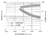
伝熱管7のピッチS1を変えて、熱伝達率U及び圧力損失ΔPを測定した。熱伝達率U及び圧力損失ΔPの傾向を図6に示す。
なお、伝熱管7の外径d0、伝熱管7のピッチS2は、以下の通りとした。
d0=25.4mm、S2=40mm
なお、伝熱管7の外径d0、伝熱管7のピッチS1は、以下の通りとした。
d0=25.4mm、S1=40mm
伝熱管7と伝熱フィン8との間に、充填材として伝熱性接着剤を施工した場合の最大の効果を熱伝達率U及び圧力損失ΔPに関し評価した。結果を図8に示す。ここで、施工する伝熱性接着剤は、接着剤自体の厚さがチューブの肉厚およびフィンの肉厚に比較し薄く、熱抵抗として無視できると想定した場合の最大効果の評価を行った。
なお、d0、S1、S2は、以下の通りとした。
d0=25.4mm、S1=40mm、S2=40mm
拡管率(%)={拡管後伝熱管外径dTO2-拡管前伝熱フィン内径dfin1}/拡管前伝熱フィン内径dfin1×100≒{(ダイス外径dD+伝熱管肉厚ΔdT)-拡管前伝熱フィン内径dfin1}/拡管前伝熱フィン内径dfin1×100
図10に示すように、拡管率が増大するほど、接合された伝熱管7と伝熱フィン8との接触熱伝達率は増加する。接触熱伝達率が約5000W/(m2・K)未満であると、接触抵抗が支配的となるため、接触熱伝達率は約5000W/(m2・K)以上であることが好ましい。一方、拡管率が1.5%以上に増大すると伝熱フィン8が伝熱管7を締め付ける弾性力が低下し、接触が緩んでしまう。その結果、伝熱フィン8の倒れ等が発生し、伝熱フィン8にゆがみが生じて寸法の精度が低下する。よって、拡管率は0.3~1.5%であることが好ましく、0.5~1.0%であることがさらに好ましい。
1…ガスクーラ本体、2…冷却水入口、3…冷却水出口、4…ガス入口、5…ガス出口
6…熱交換器、7…伝熱管、8…伝熱フィン
d0…外径、S1…ピッチ、S2…ピッチ
dD…ダイス外径、ΔdT…伝熱管肉厚、dfin1…拡管前伝熱フィン内径、dTO2…拡管後伝熱管外径
Claims (8)
- 熱交換器を備え、外部から導入される加熱された被冷却ガスと前記熱交換器との間で熱交換することで、前記被冷却ガスを冷却して外部に排出するガスクーラであって、
前記熱交換器は、
互いに所定の間隙を介して並設され、前記間隙を前記被冷却ガスが流れる複数の伝熱フィンと、
前記複数の伝熱フィンを貫通し、前記被冷却ガスが流れる向きに沿って複数列設けられる伝熱管と、を備え、
前記伝熱管の外径d0が20~30mmであることを特徴とするガスクーラ。 - 前記被冷却ガスの流れる向きに直交する方向における前記伝熱管のピッチをS1、前記被冷却ガスの流れる方向における前記伝熱管のピッチをS2とすると、S1が30~50mm、S2が30~50mmであることを特徴とする請求項1に記載のガスクーラ。
- 前記伝熱管の外径d0が23~27mmであることを特徴とする請求項1に記載のガスクーラ。
- 前記伝熱管のピッチS1及びピッチS2は35~45mmであることを特徴とする請求項2に記載のガスクーラ。
- 前記伝熱フィンと前記伝熱管とが、充填材を介して接合されていることを特徴とする請求項1又は2に記載のガスクーラ。
- 前記充填材は、伝熱性接着剤であることを特徴とする請求項5に記載のガスクーラ。
- 前記伝熱管の外径は、ダイスを前記伝熱管の内部に押し込むことで拡げられ、前記伝熱管の拡管率は0.3~1.5%であることを特徴とする請求項1に記載のガスクーラ。但し、拡管率(%)={拡管後伝熱管外径dTO2-拡管前伝熱フィン内径dfin1}/拡管前伝熱フィン内径dfin1×100≒{(ダイス外径dD+伝熱管肉厚△dT)-拡管前伝熱フィン内径dfin1}/拡管前伝熱フィン内径dfin1×100
- 前記伝熱管の前記拡管率が0.5~1.0%であることを特徴とする請求項7に記載のガスクーラ。
Priority Applications (5)
| Application Number | Priority Date | Filing Date | Title |
|---|---|---|---|
| US13/124,735 US9939209B2 (en) | 2009-02-23 | 2010-02-16 | Gas cooler |
| CN2010800030647A CN102203538B (zh) | 2009-02-23 | 2010-02-16 | 气体冷却器 |
| KR1020117009546A KR101290962B1 (ko) | 2009-02-23 | 2010-02-16 | 가스 쿨러 |
| JP2011500504A JP5638512B2 (ja) | 2009-02-23 | 2010-02-16 | ガスクーラ |
| EP10743549.7A EP2400251B1 (en) | 2009-02-23 | 2010-02-16 | Gas cooler |
Applications Claiming Priority (2)
| Application Number | Priority Date | Filing Date | Title |
|---|---|---|---|
| JP2009-039006 | 2009-02-23 | ||
| JP2009039006 | 2009-02-23 |
Publications (1)
| Publication Number | Publication Date |
|---|---|
| WO2010095419A1 true WO2010095419A1 (ja) | 2010-08-26 |
Family
ID=42633707
Family Applications (1)
| Application Number | Title | Priority Date | Filing Date |
|---|---|---|---|
| PCT/JP2010/000949 WO2010095419A1 (ja) | 2009-02-23 | 2010-02-16 | ガスクーラ |
Country Status (6)
| Country | Link |
|---|---|
| US (1) | US9939209B2 (ja) |
| EP (1) | EP2400251B1 (ja) |
| JP (1) | JP5638512B2 (ja) |
| KR (1) | KR101290962B1 (ja) |
| CN (1) | CN102203538B (ja) |
| WO (1) | WO2010095419A1 (ja) |
Cited By (3)
| Publication number | Priority date | Publication date | Assignee | Title |
|---|---|---|---|---|
| JP2012052747A (ja) * | 2010-09-02 | 2012-03-15 | Sumitomo Light Metal Ind Ltd | フィン・アンド・チューブ型熱交換器用伝熱管及びそれを用いたフィン・アンド・チューブ型熱交換器並びにその製造方法 |
| WO2013108648A1 (ja) * | 2012-01-18 | 2013-07-25 | 三菱電機株式会社 | 車両用空調装置の熱交換器および車両用空調装置 |
| WO2016009713A1 (ja) * | 2014-07-14 | 2016-01-21 | 日立アプライアンス株式会社 | 冷凍サイクル装置及びこれに使用されるクロスフィンチューブ型熱交換器の製造方法 |
Families Citing this family (2)
| Publication number | Priority date | Publication date | Assignee | Title |
|---|---|---|---|---|
| CN102492456B (zh) * | 2011-11-20 | 2013-12-18 | 中国石油化工股份有限公司 | 一种乙烯裂解炉用急冷换热器 |
| JP6472745B2 (ja) * | 2015-12-25 | 2019-02-20 | 株式会社神戸製鋼所 | ガスクーラ |
Citations (10)
| Publication number | Priority date | Publication date | Assignee | Title |
|---|---|---|---|---|
| JPS633186A (ja) | 1986-06-23 | 1988-01-08 | Matsushita Refrig Co | フインチユ−ブ型熱交換器 |
| JPH04155189A (ja) * | 1990-10-18 | 1992-05-28 | Kubota Corp | 熱交換器 |
| JPH0749189A (ja) * | 1993-08-05 | 1995-02-21 | Showa Alum Corp | 熱交換器 |
| JP2000146305A (ja) * | 1998-11-11 | 2000-05-26 | Gastar Corp | 給湯機の廃熱回収用熱交換器 |
| JP2000274982A (ja) * | 1999-03-23 | 2000-10-06 | Mitsubishi Electric Corp | 熱交換器及びそれを用いた空調冷凍装置 |
| JP2002243383A (ja) * | 2001-02-19 | 2002-08-28 | Mitsubishi Electric Corp | 熱交換器およびこれを用いた空気調和機 |
| JP2004245532A (ja) | 2003-02-14 | 2004-09-02 | Toshiba Kyaria Kk | フィンチューブ型熱交換器 |
| JP2005288502A (ja) * | 2004-03-31 | 2005-10-20 | Kobelco & Materials Copper Tube Inc | 拡管用工具およびそれを使用した拡管方法 |
| JP2008065412A (ja) | 2006-09-05 | 2008-03-21 | Mitsubishi Heavy Ind Ltd | ガスクーラにおけるガス漏れ検知システム |
| JP2008256303A (ja) | 2007-04-06 | 2008-10-23 | Nippon Spindle Mfg Co Ltd | ガスクーラ |
Family Cites Families (14)
| Publication number | Priority date | Publication date | Assignee | Title |
|---|---|---|---|---|
| FR2410237A1 (fr) | 1977-11-23 | 1979-06-22 | Thermal Waerme Kaelte Klima | Echangeur de chaleur tubulaire pour vehicules |
| US4459917A (en) * | 1982-08-30 | 1984-07-17 | Carrier Corporation | Method and apparatus for producing even tube extensions in a partially assembled heat exchanger |
| DE3528499C1 (de) | 1985-08-08 | 1987-03-12 | Konvekta Gmbh | Waermetauscher-Einrichtung mit Waermetauscher-Rohren und blechfoermigen Lamellen |
| US5323849A (en) * | 1993-04-21 | 1994-06-28 | The United States Of America As Represented By The Secretary Of The Navy | Corrosion resistant shell and tube heat exchanger and a method of repairing the same |
| US5425414A (en) * | 1993-09-17 | 1995-06-20 | Evapco International, Inc. | Heat exchanger coil assembly |
| US5381600A (en) * | 1993-10-06 | 1995-01-17 | Ford Motor Company | Heat exchanger and method of making the same |
| JPH08128793A (ja) * | 1994-10-28 | 1996-05-21 | Toshiba Corp | 内部フィン付伝熱管とその製造方法 |
| JP3300728B2 (ja) | 1994-11-14 | 2002-07-08 | 三菱重工業株式会社 | スパイラルフィンチューブを用いた熱交換器 |
| US6192974B1 (en) * | 1998-09-15 | 2001-02-27 | Xchanger, Inc. | Heat exchanger housing having conical inlet and outlet gas transitions |
| KR100374134B1 (ko) | 2000-12-26 | 2003-03-03 | 삼성전자주식회사 | 냉장고용 응축기 |
| JP2002257485A (ja) | 2001-02-27 | 2002-09-11 | Matsushita Refrig Co Ltd | 熱交換器の製造方法 |
| JP4109444B2 (ja) * | 2001-11-09 | 2008-07-02 | Gac株式会社 | 熱交換器およびその製造方法 |
| US7500513B2 (en) * | 2006-11-03 | 2009-03-10 | Fu Zhun Precision Industry (Shen Zhen) Co., Ltd. | Heat-pipe type heat sink |
| US7578179B2 (en) * | 2007-03-30 | 2009-08-25 | Southwest Research Institute | Exhaust gas simulation system with dual path temperature control for control of exhaust temperature |
-
2010
- 2010-02-16 US US13/124,735 patent/US9939209B2/en active Active
- 2010-02-16 CN CN2010800030647A patent/CN102203538B/zh not_active Expired - Fee Related
- 2010-02-16 JP JP2011500504A patent/JP5638512B2/ja active Active
- 2010-02-16 EP EP10743549.7A patent/EP2400251B1/en active Active
- 2010-02-16 KR KR1020117009546A patent/KR101290962B1/ko active IP Right Grant
- 2010-02-16 WO PCT/JP2010/000949 patent/WO2010095419A1/ja active Application Filing
Patent Citations (10)
| Publication number | Priority date | Publication date | Assignee | Title |
|---|---|---|---|---|
| JPS633186A (ja) | 1986-06-23 | 1988-01-08 | Matsushita Refrig Co | フインチユ−ブ型熱交換器 |
| JPH04155189A (ja) * | 1990-10-18 | 1992-05-28 | Kubota Corp | 熱交換器 |
| JPH0749189A (ja) * | 1993-08-05 | 1995-02-21 | Showa Alum Corp | 熱交換器 |
| JP2000146305A (ja) * | 1998-11-11 | 2000-05-26 | Gastar Corp | 給湯機の廃熱回収用熱交換器 |
| JP2000274982A (ja) * | 1999-03-23 | 2000-10-06 | Mitsubishi Electric Corp | 熱交換器及びそれを用いた空調冷凍装置 |
| JP2002243383A (ja) * | 2001-02-19 | 2002-08-28 | Mitsubishi Electric Corp | 熱交換器およびこれを用いた空気調和機 |
| JP2004245532A (ja) | 2003-02-14 | 2004-09-02 | Toshiba Kyaria Kk | フィンチューブ型熱交換器 |
| JP2005288502A (ja) * | 2004-03-31 | 2005-10-20 | Kobelco & Materials Copper Tube Inc | 拡管用工具およびそれを使用した拡管方法 |
| JP2008065412A (ja) | 2006-09-05 | 2008-03-21 | Mitsubishi Heavy Ind Ltd | ガスクーラにおけるガス漏れ検知システム |
| JP2008256303A (ja) | 2007-04-06 | 2008-10-23 | Nippon Spindle Mfg Co Ltd | ガスクーラ |
Non-Patent Citations (1)
| Title |
|---|
| See also references of EP2400251A4 * |
Cited By (5)
| Publication number | Priority date | Publication date | Assignee | Title |
|---|---|---|---|---|
| JP2012052747A (ja) * | 2010-09-02 | 2012-03-15 | Sumitomo Light Metal Ind Ltd | フィン・アンド・チューブ型熱交換器用伝熱管及びそれを用いたフィン・アンド・チューブ型熱交換器並びにその製造方法 |
| WO2013108648A1 (ja) * | 2012-01-18 | 2013-07-25 | 三菱電機株式会社 | 車両用空調装置の熱交換器および車両用空調装置 |
| JPWO2013108648A1 (ja) * | 2012-01-18 | 2015-05-11 | 三菱電機株式会社 | 車両用空調装置の熱交換器および車両用空調装置 |
| WO2016009713A1 (ja) * | 2014-07-14 | 2016-01-21 | 日立アプライアンス株式会社 | 冷凍サイクル装置及びこれに使用されるクロスフィンチューブ型熱交換器の製造方法 |
| JP2016020757A (ja) * | 2014-07-14 | 2016-02-04 | 日立アプライアンス株式会社 | 冷凍サイクル装置及びこれに使用されるクロスフィンチューブ型熱交換器の製造方法 |
Also Published As
| Publication number | Publication date |
|---|---|
| EP2400251A4 (en) | 2013-01-16 |
| KR20110060957A (ko) | 2011-06-08 |
| EP2400251B1 (en) | 2014-09-24 |
| US9939209B2 (en) | 2018-04-10 |
| CN102203538A (zh) | 2011-09-28 |
| EP2400251A1 (en) | 2011-12-28 |
| CN102203538B (zh) | 2013-08-14 |
| JP5638512B2 (ja) | 2014-12-10 |
| KR101290962B1 (ko) | 2013-07-30 |
| JPWO2010095419A1 (ja) | 2012-08-23 |
| US20110277960A1 (en) | 2011-11-17 |
Similar Documents
| Publication | Publication Date | Title |
|---|---|---|
| JP5638512B2 (ja) | ガスクーラ | |
| WO2014147788A1 (ja) | 熱交換器、冷凍サイクル装置、及び熱交換器の製造方法 | |
| EP3062037B1 (en) | Heat exchanger and refrigeration cycle device using said heat exchanger | |
| CN101900459A (zh) | 一种微通道平行流换热器 | |
| JP2006322661A (ja) | 放熱用伝熱管および放熱器 | |
| JP2006189249A (ja) | 二重管熱交換器 | |
| JP6220692B2 (ja) | 熱交換器 | |
| CN212205788U (zh) | 换热器及空调器 | |
| CN210153965U (zh) | 散热组件及空调器 | |
| JP2015148392A5 (ja) | ||
| CN209877159U (zh) | 辐射对流式换热器及具有其的空调器 | |
| WO2011152343A1 (ja) | 熱交換器及びこれを用いたヒートポンプ装置 | |
| CN111435018A (zh) | 辐射对流式换热器及具有其的空调器 | |
| CN209877231U (zh) | 空调系统 | |
| CN209877157U (zh) | 辐射对流式换热器及具有其的空调器 | |
| CN209877232U (zh) | 空调系统 | |
| CN210463544U (zh) | 一种空调及其换热器组件 | |
| JP4948136B2 (ja) | 放熱用伝熱管および放熱器 | |
| CN209877163U (zh) | 辐射对流式换热器及具有其的空调器 | |
| CN209877154U (zh) | 辐射对流式换热器及具有其的空调器 | |
| CN209877162U (zh) | 辐射对流式换热器及具有其的空调器 | |
| CN209877153U (zh) | 辐射对流式换热器及具有其的空调器 | |
| CN107906729B (zh) | 换热装置及空调设备 | |
| KR20100034791A (ko) | 냉온풍을 겸용 공급하는 이중진공중합관의 열교환기 | |
| JP2010127547A (ja) | 冷凍サイクル装置 |
Legal Events
| Date | Code | Title | Description |
|---|---|---|---|
| WWE | Wipo information: entry into national phase |
Ref document number: 201080003064.7 Country of ref document: CN |
|
| 121 | Ep: the epo has been informed by wipo that ep was designated in this application |
Ref document number: 10743549 Country of ref document: EP Kind code of ref document: A1 |
|
| WWE | Wipo information: entry into national phase |
Ref document number: 723/MUMNP/2011 Country of ref document: IN |
|
| ENP | Entry into the national phase |
Ref document number: 2011500504 Country of ref document: JP Kind code of ref document: A |
|
| ENP | Entry into the national phase |
Ref document number: 20117009546 Country of ref document: KR Kind code of ref document: A |
|
| WWE | Wipo information: entry into national phase |
Ref document number: 2010743549 Country of ref document: EP |
|
| WWE | Wipo information: entry into national phase |
Ref document number: 13124735 Country of ref document: US |
|
| NENP | Non-entry into the national phase |
Ref country code: DE |