WO2010087324A1 - 飲料容器用フィッティング - Google Patents
飲料容器用フィッティング Download PDFInfo
- Publication number
- WO2010087324A1 WO2010087324A1 PCT/JP2010/050950 JP2010050950W WO2010087324A1 WO 2010087324 A1 WO2010087324 A1 WO 2010087324A1 JP 2010050950 W JP2010050950 W JP 2010050950W WO 2010087324 A1 WO2010087324 A1 WO 2010087324A1
- Authority
- WO
- WIPO (PCT)
- Prior art keywords
- fitting
- beverage container
- mounting member
- base
- beverage
- Prior art date
- Legal status (The legal status is an assumption and is not a legal conclusion. Google has not performed a legal analysis and makes no representation as to the accuracy of the status listed.)
- Ceased
Links
Images


Classifications
-
- B—PERFORMING OPERATIONS; TRANSPORTING
- B67—OPENING, CLOSING OR CLEANING BOTTLES, JARS OR SIMILAR CONTAINERS; LIQUID HANDLING
- B67D—DISPENSING, DELIVERING OR TRANSFERRING LIQUIDS, NOT OTHERWISE PROVIDED FOR
- B67D1/00—Apparatus or devices for dispensing beverages on draught
- B67D1/08—Details
- B67D1/0829—Keg connection means
- B67D1/0831—Keg connection means combined with valves
- B67D1/0832—Keg connection means combined with valves with two valves disposed concentrically
-
- B—PERFORMING OPERATIONS; TRANSPORTING
- B67—OPENING, CLOSING OR CLEANING BOTTLES, JARS OR SIMILAR CONTAINERS; LIQUID HANDLING
- B67D—DISPENSING, DELIVERING OR TRANSFERRING LIQUIDS, NOT OTHERWISE PROVIDED FOR
- B67D1/00—Apparatus or devices for dispensing beverages on draught
- B67D1/08—Details
- B67D1/0829—Keg connection means
- B67D1/0831—Keg connection means combined with valves
- B67D1/0838—Keg connection means combined with valves comprising means for preventing blow-out on disassembly of the spear valve
Definitions
- the present invention relates to a fitting for a beverage container that is fixed to a base of a beverage container such as a beer barrel and is connected to a dispense head, and more particularly, an easy disassembly of a fitting by a third party and a beverage container
- the present invention relates to a beverage container fitting that can prevent unauthorized use and contamination and can significantly reduce maintenance work.
- a base is fixed to the beverage container by welding or the like, and a fitting is screwed into the base.
- a dispensing head is connected to the fitting.
- a pressure gas such as carbon dioxide is supplied into the beverage container via the dispense head, and the beverage in the beverage container is poured out of the container.
- FIG. 11 is a front sectional view showing a state where a conventional fitting is attached to the beverage container 8.
- the beverage is a draft beer and the beverage container is a beer barrel.
- a fitting mounting member 2 is screwed and fixed inside a base 9 provided at the upper part of the beverage container 8.
- a down tube 5 urged upward by a coil spring 61 is attached to the attachment member 2.
- the lower side of the mounting member 2 is a skirt-like frame portion 25.
- a central hole is provided in the bottom surface of the frame portion 25, and components such as the down tube 5 and the coil spring 61 are inserted into the frame portion 25 from below through the central hole.
- a detachable stopper 253 is attached to the bottom surface of the frame portion 25 to support the lower end of the coil spring 61, and each component is held in the frame portion 25. That is, after all the components such as the down tube 5 and the gas valve 3 are assembled in the mounting member 2, the mounting member 2 is screwed into the base 9 and fixed.
- the gas valve 3 is fixed to the upper end of the down tube 5, and the beer valve 4 is urged upward by a coil spring 62 inside the upper end of the down tube 5.
- the gas valve 3 and the beer valve 4 are closed by the urging force of the coil springs 61 and 62.
- a dispense head can be attached to the base 9 and the attachment member 2.
- the dispense head and the attachment member 2 can be easily coupled by a connection mechanism using the engagement protrusion 22.
- the dispense head operates the gas valve 3 and the beer valve 4, supplies a pressure gas such as carbon dioxide gas into the beverage container 8, and increases the internal pressure of the beverage container 8 so that draft beer is poured out of the container. It is. Draft beer is poured out of the container through the down tube 5 and the beer valve 4.
- a seal ring 27 is provided between the lower inner surface of the base 9 and the mounting member 2.
- the pop-out preventing member 7 prevents the mounting member 2 from popping out due to the gas pressure in the beverage container 8 when the mounting member 2 is removed from the base 9.
- the stopper 71 is brought into contact with the lower surface of the base 9 to prevent popping out.
- the gas valve 3 is pushed down by the removal tool, the pressure gas escapes from the beverage container 8 and the stopper 71 retracts inside, so that the attachment member 2 can be removed from the base 9.
- the sewage in this gap boils and spouts out, so it can be confirmed that the sewage has accumulated in this gap.
- the sewage in the gap may thermally expand and ooze out of the gap, or may enter the base and contaminate draft beer.
- Patent Document 1 in addition to the first sealing member that seals the gap between the lower inner surface of the base and the mounting member, a second sealing member is also provided at the uppermost part of the fitting. This makes it difficult for foreign matter or sewage to enter the gap.
- the conventional fitting shown in FIG. 11 has a problem that sewage or the like tends to accumulate in the gap between the base 9 and the mounting member 2. Furthermore, in the conventional fitting, since the attachment member 2 can be removed from the base 9 relatively easily, there is a case where a third party removes the fitting of the beverage container 8 together with the attachment member 2 and diverts it for private use. Not a little. In addition, there is a case where the fitting is attached again to the beverage container 8 whose inside is contaminated by such diversion and returned to the regular distribution path of the beverage container 8.
- a seal ring 27 is disposed between the base 9 and the mounting member 2 to seal between the base 9 and the mounting member 2.
- the seal ring 27 is directly subjected to a screwing force when the mounting member 2 is screwed and fixed to the base 9.
- the beverage container 8 is used repeatedly such as beverage filling, transporting, returning, and washing.
- the attachment member 2 is tightened to a specified torque in the beverage container cleaning operation line.
- the seal ring 27 deteriorates due to a large amount of screwing force of the mounting member 2 acting on the seal ring 27 over a long period of time or mechanical wear due to tightening of the mounting member 2.
- the lifetime of is relatively short.
- the seal ring 27 had to be replaced almost every 3 to 5 years.
- the fitting of Patent Document 1 is provided with a second sealing member in addition to the first sealing member, so that foreign matter, sewage and the like are less likely to enter the gap between the base and the mounting member.
- a second sealing member in addition to the first sealing member, so that foreign matter, sewage and the like are less likely to enter the gap between the base and the mounting member.
- the first sealing member and the second sealing member are also made of a flexible material such as rubber, deterioration due to wear or corrosion is inevitable, and periodic replacement is necessary.
- the frequency of the maintenance work can be reduced also by the fitting of Patent Document 1, it is necessary to periodically perform the sterilization / cleaning work and the replacement work of the first sealing member and the second sealing member.
- the 1st sealing member in the fitting of patent document 1 is a function substantially the same as the seal ring of the conventional fitting, and its lifetime is also comparable.
- Patent Document 1 has the same problems as the conventional fitting because the mounting member can be removed from the base relatively easily. That is, unauthorized use of the beverage container could not be prevented.
- the present invention can prevent easy disassembly of fitting by a third party and unauthorized use or contamination of a beverage container, and can prolong the life of a seal ring and greatly reduce maintenance work.
- An object is to provide a beverage container fitting.
- the beverage container fitting according to the present invention is a fitting that is screwed into and attached to a female screw formed on the inner peripheral side of the mouthpiece of the beverage container, and is screwed with the female screw of the mouthpiece.
- a mounting member provided on the outer peripheral side, a valve seat provided on the inner peripheral side of the mounting member, a tubular down tube whose upper end is supported by the mounting member, and an upper end of the down tube
- a sealing member that seals between an inner surface and the mounting member, and the mounting member is formed with a collar portion protruding outward from a top portion, and the collar portion is formed of the base. Abut the upper end, the mounting part The mounting member is screwed into the base, and is screwed and fixed to a predetermined position defined by the collar, and further, the collar and the base Are fixed to prevent the attachment member from rotating.
- the collar portion and the base are fixed by welding at one point or a plurality of points.
- the attachment member is integrally formed as a skirt-like frame portion on the lower side, and the attachment member is an outer periphery in the vicinity of the upper end of the frame portion. It is preferable that a sealing groove for holding the sealing member is formed on the surface.
- the seal groove is formed at a position where the pressure applied to the sealing member becomes an appropriate value in a state where the mounting member is fixed to the base. Preferably there is.
- the sealing member is an arcuate curve in which a contour line on the outer peripheral side of the cross-sectional shape swells outward.
- the sealing groove has an inclined pressure surface for pressurizing the sealing member, and a force is applied to the sealing member to expand outwardly when pressurized. It is preferable that
- the attachment member is made of austenitic stainless steel in the frame portion and duplex stainless steel in the other portions.
- valve seat portion is provided with two conical surfaces having different inclination angles.
- the attachment member may be one in which the collar portion is integrally fixed to the attachment member without the collar portion.
- the seal groove is formed at a position where the pressure applied to the sealing member is an appropriate value, an appropriate pressure can be reliably applied to the sealing member, and the sealing performance of the sealing member can be improved. While being able to fully exhibit, without enlarging stress and distortion to a sealing member, the lifetime of a sealing member can be prolonged significantly. As a result, there is almost no need to replace the sealing member, and maintenance costs can be reduced.
- valve seat portion has two conical surfaces with different inclination angles, the movement of the gas valve in the horizontal plane can be restricted by a restriction surface closer to the vertical direction than the valve seat surface. The amount of displacement from the center position can be kept small.
- the mounting member of the fitting that has been widely used and has been widely used in the past has been modified.
- the fitting of the present invention can be provided at a very low cost.
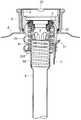
- FIG. 1 is a cross-sectional view showing a configuration of a beverage container fitting according to a first embodiment of the present invention.
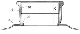
- FIG. 2 is a cross-sectional view showing the configuration of the base 9 of the beverage container 8.
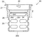
- FIG. 3 is a cross-sectional view showing the configuration of the mounting member 20.
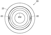
- FIG. 4 is a plan view of the mounting member 20 as viewed from above.
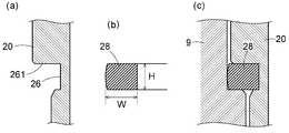
- FIG. 5 is an enlarged cross-sectional view showing the cross-sectional shapes of the seal groove 26 and the seal ring 28 of the mounting member 20.
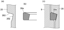
- FIG. 6 is an enlarged cross-sectional view showing the cross-sectional shapes of the seal groove 26a and the seal ring 28a of another form of the mounting member 20. As shown in FIG. FIG. FIG.
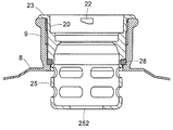
- FIG. 7 is a cross-sectional view showing a state in which the attachment member 20 is incorporated in the base 9.
- FIG. 8 is a plan view of the mounting member 20 incorporated in the base 9 as viewed from above.
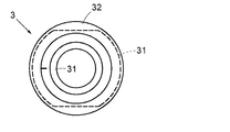
- FIG. 9 is a plan view of the gas valve 3 as viewed from above.
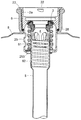
- FIG. 10 is sectional drawing which shows the structure of the fitting for drink containers of the 2nd Embodiment of this invention.
- FIG. 11 is a front sectional view showing a state where a conventional fitting is attached to the beverage container 8.
- FIG. 1 is a cross-sectional view showing a configuration of a beverage container fitting according to a first embodiment of the present invention.
- FIG. 1 is a cross-sectional view seen from the front showing a state in which the beverage container fitting of the present invention is incorporated in the base 9 of the beverage container 8.
- FIG. 2 is a cross-sectional view showing the configuration of the base 9 of the beverage container 8.
- a base 9 as shown is connected and fixed to the top of the beverage container 8 by welding or the like.
- the connecting portion between the beverage container 8 and the base 9 is liquid-tight and air-tight so that there is no leakage of liquid or gas.
- the base 9 is formed in a substantially cylindrical shape and is hollow inside.
- a female thread 91 is formed at the upper part of the inner peripheral surface of the base 9.
- a step portion 92 is formed at the lowermost portion on the inner peripheral side of the base 9.
- the step portion 92 has a structure for receiving a seal ring 28 to be described later and sealing with the seal ring 28.
- FIG. 3 is a cross-sectional view showing the configuration of the mounting member 20 for mounting on the inner peripheral side of the base 9.
- FIG. 4 is a plan view of the mounting member 20 as viewed from above.
- the attachment member 20 is a member that constitutes a fitting main body by supporting each part of the fitting, and its basic shape is substantially cylindrical.
- a flange 23 that extends radially outward is integrally provided at the uppermost portion of the mounting member 20.
- a male screw 21 is formed on the outer periphery of the mounting member 20. The male screw 21 is formed over a predetermined length from a position near the lower portion of the flange portion 23. The male screw 21 is screwed into the female screw 91 of the base 9.
- An engaging protrusion 22 that protrudes inward is formed on the inner peripheral surface of the mounting member 20.
- the engagement protrusion 22 is a structure for fixing the dispense head to the upper surface of the base 9. As shown in FIG. 4, two engagement protrusions 22 are formed at positions facing the diameter direction of the inner peripheral surface of the attachment member 20. The dispense head and the attachment member 20 can be easily coupled by a connection mechanism using the engagement protrusion 22.
- valve seat portion 24 is formed in the middle step on the inner peripheral surface of the mounting member 20.
- the valve seat portion 24 is constituted by a part of a conical inner surface having a single inclination angle, and the apex angle of the conical surface is 60 degrees. That is, the angle (1/2 of the apex angle) between the center line of the conical surface (here, the vertical direction) and the generatrix of the conical surface is 30 degrees.
- the valve seat portion 24 is composed of an upper valve seat surface 241 and a lower regulating surface 242 as shown in the figure.
- Each surface of the valve seat surface 241 and the regulating surface 242 is a conical inner surface having a common center line, but the inclination angles thereof are different.
- the apex angle of the valve seat surface 241 is preferably in the range of 80 to 110 degrees, and is typically set to 90 degrees. That is, the angle formed between the center line of the conical surface and the generatrix is preferably in the range of 40 to 55 degrees, and is typically set to 45 degrees.
- the apex angle of the regulating surface 242 is preferably in the range of 30 to 50 degrees, and is typically set to 40 degrees. That is, the angle formed between the center line of the conical surface and the generatrix is preferably in the range of 15 to 25 degrees, and is typically set to 20 degrees.
- the inclination direction of the restriction surface 242 is closer to the vertical direction than the conventional valve seat surface, the action of restricting the movement of the gas valve 3 in the horizontal plane works strongly. For this reason, the amount of displacement from the center position of the gas valve 3 can be kept small.
- the lower side of the mounting member 20 is a skirt-like frame portion 25.
- the frame portion 25 supports the coil spring 61 and the down tube 5 (see FIG. 1).
- a plurality of window portions 251 are formed on the cylindrical side surface of the frame portion 25.
- the window part 251 is an opening for allowing carbon dioxide gas or the like to pass therethrough.
- a central hole 252 for allowing the down tube 5 to pass therethrough is formed on the bottom surface of the frame portion 25.
- the central hole 252 has such a size that the upper large diameter portion of the down tube 5 can pass through, and the coil spring 61 is supported by the peripheral edge of the central hole 252 (see FIG. 1).
- the attachment member 20 is formed by integrally joining a main body portion (including the flange portion 23) other than the frame portion 25 and the frame portion 25 by welding.
- the main body portion (including the flange portion 23) is integrally formed of duplex stainless steel, and the frame portion 25 is made of austenitic stainless steel.
- the duplex stainless steel is a stainless steel consisting of two phases of austenite and ferrite and excellent in strength, hardness and corrosion resistance. In general, the duplex stainless steel exhibits higher strength and higher hardness than ordinary austenitic stainless steel. As the duplex stainless steel, for example, one having a two-phase structure of about 50% ferrite phase and about 50% austenite phase can be used.
- a seal groove 26 for holding the seal ring 28 is formed on the outer peripheral surface of the mounting member 20 so as to surround the entire outer periphery of the mounting member 20.
- the main body portion and the frame portion 25 of the mounting member 20 are integrally joined at a position near the seal groove 26.
- FIG. 5 is an enlarged cross-sectional view showing the cross-sectional shapes of the seal groove 26 and the seal ring 28 of the mounting member 20.
- 5A is an enlarged cross-sectional view showing the cross-sectional shape of the seal groove 26
- FIG. 5B is an enlarged cross-sectional view showing the cross-sectional shape of the seal ring 28
- FIG. 4 is an enlarged cross-sectional view showing a state in which a seal ring 28 is incorporated in a base 9.
- the pressure surface 261 is a surface that pressurizes the seal ring 28 downward.
- the seal ring 28 is pressurized between the pressure surface 261 and the step portion 92 of the base 9. This pressure exerts the sealing performance of the seal ring 28.
- the pressing surface 261 is formed to be a horizontal plane (a plane orthogonal to the central axis of the mounting member 20).
- the depth of the seal groove 26 is larger than that of the conventional fitting. Therefore, the area of the pressure surface 261 is increased as compared with the conventional case. As a result, the pressure applied to the seal ring 28 is distributed over a wide area, and the life of the seal ring 28 can be greatly prolonged compared to the conventional case.
- FIG. 5B is a cross-sectional view showing a cross-sectional shape of the seal ring 28 attached to the seal groove 26.
- the seal ring 28 in the fitting of the present invention has a larger cross-sectional area than the seal ring 27 in the fitting conventionally used, and the pressing force for sealing is widely dispersed. For this reason, the life of the seal ring 28 can be significantly prolonged as compared with the prior art.
- the seal ring 28 in the fitting of the present invention can apply only the pressure necessary for sealing the gas / liquid, excessive stress and distortion are generated in the seal ring 28. This also makes it possible to prolong the life of the seal ring 28 significantly. Also, the material of the seal ring 28 does not need to be considered for resistance to excessive screwing force and wear resistance unlike the conventional seal ring, and the optimum material should be selected considering only the sealing performance and the life. Can do.
- the cross-sectional area of the cross-sectional shape of the seal ring 28 is larger than that of the conventional seal ring 27.
- the width in the cross-sectional shape of the seal ring is W
- the height is H.
- the conventional seal ring 27 has a rectangular cross section with a width W of 2.2 mm and a height H of 3.0 mm, and the cross sectional area was 6.6 mm 2 .
- the width W is 3.0 mm
- the height H is 3.0 mm
- the cross-sectional area is 9.0 mm 2 .
- the seal ring 28 of the present invention has a cross-sectional area of 1.36 times that of the conventional seal ring.
- the cross-sectional shape of the seal ring 28 may be a perfect square, but as shown in FIG. 5 (b), it is preferable that the outline of the outer peripheral surface is an arcuate curve. As shown in the figure, the inner peripheral side, upper side, and lower side contour lines of the cross-sectional shape of the seal ring 28 are straight lines, but the outer peripheral side contour line is an arc-shaped curve whose central portion swells outward. . Note that the outline of the cross-sectional shape of the seal ring 28 may be all straight and the cross-sectional shape may be square (or rectangular).
- FIG. 6 is an enlarged cross-sectional view showing a cross-sectional shape of another form of the seal groove 26a and the seal ring 28a.
- FIG. 6 shows a seal groove 26a and a seal ring 28a having a cross-sectional shape different from that in FIG. 6A is an enlarged cross-sectional view showing the cross-sectional shape of the seal groove 26a
- FIG. 6B is an enlarged cross-sectional view showing the cross-sectional shape of the seal ring 28a
- FIG. FIG. 4 is an enlarged cross-sectional view showing a state in which a seal ring 28a is incorporated in a base 9.
- the cross-sectional shape of the seal ring 28a is set as shown in FIG. 6B so as to be adapted to the cross-sectional shape of the seal groove 26a.
- the cross-sectional area can be increased to about 1.8 times that of the conventional seal ring.
- the cross-sectional shape of the seal ring is adapted to the cross-sectional shape of the seal groove and the cross-sectional area is made as large as possible.
- the pressurizing surface 262 is inclined as shown in the figure, so that when the seal ring 28a is pressed downward by the pressurizing surface 262, the seal ring 28a is pushed outward. Forces to expand. For this reason, the seal ring 28a is pressed more strongly against the inner peripheral surface of the base 9, and the sealing performance is improved.
- FIG. 6C shows a state where the seal ring 28a is not yet pressed downward. From this state, when the seal ring 28a is pressed downward by the inclined pressure surface 262, the seal ring 28a is pushed outward, and the outer peripheral surface of the seal ring 28a is brought into close contact with the inner peripheral surface of the base 9 to provide a strong seal. The stopping performance will be demonstrated.
- FIG. 7 is a cross-sectional view showing a state in which the attachment member 20 is incorporated in the base 9.
- FIG. 8 is a plan view of the mounting member 20 incorporated in the base 9 as viewed from above.
- the seal ring 28 is sandwiched between the pressure surface 261 and the stepped portion 92 and is pressurized with an appropriate pressure. That is, the distance T (see FIG. 3) between the lower surface of the collar portion 23 and the pressure surface 261 is set so that the pressure applied to the seal ring 28 becomes an appropriate value when the mounting member 20 is fixed.
- K is 28.5 mm
- H is the height of the cross-sectional shape of the seal ring 28
- ⁇ is the compression amount in the vertical direction of the seal ring 28 for applying an appropriate pressure to the seal ring 28. .
- FIG. 8 shows a state in which the attachment member 20 is fixed to the base 9.
- a fixing point 231 indicated by “X” indicates a case where the fixing is performed by spot welding.
- the fixing points 231 are not limited thereto, and may be one or any number of three or more. However, multiple locations are desirable to prevent the fitting from being disassembled.
- the fixing point 232 indicates a case where the fixing is performed by arc welding (dot welding).
- arc welding welding
- the outer peripheral edge of the flange portion 23 and the upper surface of the base 9 are fixed by arc welding.
- two fixing points 232 are shown in FIG. 8, the number of fixing points 232 is not limited thereto, and may be an arbitrary number of three or more. In addition, it is not necessary to perform both the spot welding and the arc welding, and either one is sufficient.
- the mounting member 20 when it is necessary to remove the mounting member 20 from the base 9 such as when the seal ring 28 is deteriorated or damaged, it is also possible to remove the mounting member 20 using a dedicated removal tool. In that case, first, the fixing part by welding or the like is peeled and separated by a dedicated tool, and the detent by fixing is released. Thereafter, the screw fixing of the attachment member 20 is loosened with a dedicated tool, and the attachment member 20 is removed from the base 9.
- the seal ring 28 when the seal ring 28 is deteriorated and damaged and the sealing performance is impaired, the pressurized gas in the beverage container leaks from the seal ring 28 and further, a minute amount between the collar portion 23 and the base 9 is small. Since it leaks from the gap, the state can be easily confirmed with the naked eye. Thus, when the seal ring 28 deteriorates, it is also an advantage of the present invention that it can be confirmed immediately. In addition, you may form the ditch
- the gap between the collar 23 and the base 9 is very small, and the gap opens laterally near the periphery of the base 9, so that foreign matter, sewage, etc. may enter through this gap. Is very small. If foreign matter or sewage enters the gap, even if the sewage oozes out from the gap, the gap is opened sideways near the periphery of the base 9. There is no intrusion.
- the fitting parts are assembled in the frame portion 25 of the attachment member 20.
- the procedure for assembling the components is as follows. First, the beer valve 4 and the coil spring 62 are inserted into the upper end of the down tube 5, the coil spring 61 is disposed outside the upper end of the down tube 5, and they are attached to the frame of the mounting member 20. Insert into the part 25 from above. Finally, the gas valve 3 is attached to the upper end of the down tube 5 and fixed.
- FIG. 9 is a diagram illustrating an example of the configuration of the gas valve 3, and is a plan view of the gas valve 3 as viewed from above.
- the gas valve 3 is formed by integrally forming a valve member 32 made of a flexible member such as rubber and a cored bar 31 made of stainless steel or the like.
- a cored bar 31 made of stainless steel or the like.
- the portion where the flat portion is provided has a dimension capable of passing through the central hole of the valve seat portion 24. That is, the short diameter dimension of the core metal 31 is smaller than the diameter of the central hole of the valve seat portion 24, and the long diameter dimension of the core metal 31 is larger than the diameter of the central hole of the valve seat portion 24.
- the gas valve 3 is engraved with a mark indicating the major axis direction. Such a gas valve 3 can be assembled to the upper end of the down tube 5 by inclining in the major axis direction and passing through the valve seat portion 24 from above.
- FIG. 1 is a cross-sectional view seen from the front showing a state in which the beverage container fitting of the present invention is incorporated in the base 9 of the beverage container 8.
- the gas valve 3 is fixed to the upper end of the down tube 5, and the beer valve 4 is disposed inside the upper end of the down tube 5 by being biased upward by a coil spring 62.
- the gas valve 3 and the beer valve 4 are closed by the urging force of the coil springs 61 and 62.
- a dispense head can be attached to the base 9 and the attachment member 20. The dispense head and the attachment member 20 can be easily coupled by a connection mechanism using the engagement protrusion 22.
- the gas head 3 and the beer valve 4 are opened by operating the dispense head, pressure gas such as carbon dioxide gas is supplied into the beverage container 8, and the internal pressure of the beverage container 8 is adjusted. Draft beer can flow out of the container. Draft beer flows out of the container through the down tube 5 and the beer valve 4.
- the fitting of the present invention In order to use the fitting of the present invention as described above, it is possible to remove the conventional fitting from the beverage container 8 as shown in FIG. 11 which has been widely used and replace it with the fitting of the present invention. it can. Since the conventional beverage container 8 and the base 9 can be used as they are, the fitting of the present invention can be used at low cost.
- FIG. 10 is sectional drawing which shows the structure of the fitting for drink containers of the 2nd Embodiment of this invention.
- the same reference numerals are given to members common to the conventional fitting of FIG. 11 or the fitting of the present invention of FIG. Moreover, description of a common member is abbreviate
- the fitting attachment member 2a is screwed and fixed inside the base 9 provided at the upper part of the beverage container 8.
- This attachment member 2a is obtained by fixing a collar portion 23 to the upper end of a conventional fitting attachment member 2 by welding or the like.
- the conventional fitting member 2 can be modified to a fitting member 2a having the same function as the fitting member 20 of the first embodiment.
- each part of the fitting to the mounting member 2a is the same as the conventional fitting.
- Each component such as the down tube 5 and the coil spring 61 is inserted into the frame portion 25 from below through the center hole on the bottom surface of the frame portion 25, and then a detachable stopper 253 is attached to the bottom surface of the frame portion 25. Support the lower end of the. Thereby, each component is held in the frame portion 25.
- the mounting member 2a is screwed into the base 9 and fixed.
- the collar 23 and the base 9 are fixed by welding or the like to prevent the mounting member 2a from rotating, similarly to the fitting of the first embodiment.
- welding such as spot welding or arc welding is preferable, but other fixing methods such as adhesion can also be used.
- the fixed state is the same as that shown in FIG.
- the fitting member 2 of the fitting that has been used widely and has been widely used in the past can be modified to be the mounting member 2a of the present invention. Can be diverted almost, so the fitting of the present invention can be provided at a very low cost. Other advantages are the same as the fitting of the first embodiment.
- the beverage container fitting of the present invention by fixing the collar portion 23 and the base 9, it becomes difficult to loosen and remove the screw fixing of the mounting member 20, and the fitting by a third party. Can be prevented from being easily decomposed. And the unauthorized use and contamination of the beverage container by a third party can be prevented.
- the seal rings 28 and 28a are not subjected to excessive stress or distortion, and the life of the seal rings 28 and 28a can be greatly prolonged. it can. As a result, there is almost no need to replace the seal rings 28, 28a, and maintenance costs can be reduced.
- the possibility that foreign matter or sewage enters from the gap between the collar 23 and the base 9 is very small, and even if foreign matter or sewage enters the gap, the sewage oozes out from the gap and enters the base.
- the possibility of penetrating into the water is very small, and a fitting that is hygienic can be provided.
- draft beer is used as a beverage and a beer barrel is used as a beverage container.
- the present invention can be applied to any other beverage and beverage container.
- the fitting for drink containers which can prevent easy decomposition
Landscapes
- Devices For Dispensing Beverages (AREA)
Applications Claiming Priority (2)
| Application Number | Priority Date | Filing Date | Title |
|---|---|---|---|
| JP2009019518A JP2010173710A (ja) | 2009-01-30 | 2009-01-30 | 飲料容器用フィッティング |
| JP2009-019518 | 2009-01-30 |
Publications (1)
| Publication Number | Publication Date |
|---|---|
| WO2010087324A1 true WO2010087324A1 (ja) | 2010-08-05 |
Family
ID=42395585
Family Applications (1)
| Application Number | Title | Priority Date | Filing Date |
|---|---|---|---|
| PCT/JP2010/050950 Ceased WO2010087324A1 (ja) | 2009-01-30 | 2010-01-26 | 飲料容器用フィッティング |
Country Status (2)
| Country | Link |
|---|---|
| JP (1) | JP2010173710A (enExample) |
| WO (1) | WO2010087324A1 (enExample) |
Families Citing this family (1)
| Publication number | Priority date | Publication date | Assignee | Title |
|---|---|---|---|---|
| JP6467162B2 (ja) * | 2014-08-01 | 2019-02-06 | コーンズテクノロジー株式会社 | ビール樽 |
Citations (12)
| Publication number | Priority date | Publication date | Assignee | Title |
|---|---|---|---|---|
| JPS5926491A (ja) * | 1982-07-07 | 1984-02-10 | グランデイ(テデイングトン)リミテツド | 飲料容器の注ぎ口ハウジング用抽出管頭部取付装置 |
| JPH07503217A (ja) * | 1991-10-18 | 1995-04-06 | ロイヤル・パッケイジング・インダストリーズ・ファン・レール・ベスローテン・フェンノートシャップ | 流体配分装置 |
| JPH0796997A (ja) * | 1993-09-22 | 1995-04-11 | Kirin Brewery Co Ltd | スピアバルブの飛び出し防止機構 |
| JPH07251857A (ja) * | 1994-03-11 | 1995-10-03 | Nasu Tooa Kk | 生ビール樽 |
| JPH10318373A (ja) * | 1997-05-14 | 1998-12-04 | Morisei Kako:Kk | 封止材 |
| JP2000079991A (ja) * | 1998-07-01 | 2000-03-21 | Fuji Techno Kk | 飲料容器用フィッティング |
| JP2000335690A (ja) * | 1999-05-31 | 2000-12-05 | Fuji Techno Kk | 液体容器 |
| JP2001140718A (ja) * | 1999-11-12 | 2001-05-22 | Yachiyo Industry Co Ltd | 合成樹脂製燃料タンクのシール部の構造 |
| JP2001324022A (ja) * | 2000-05-12 | 2001-11-22 | Mutsubishi Rubber Co Ltd | 開閉蓋のシール構造 |
| JP2002250446A (ja) * | 2001-02-22 | 2002-09-06 | Mitsubishi Heavy Ind Ltd | ボルト接合部のシール構造 |
| JP2007055612A (ja) * | 2005-08-22 | 2007-03-08 | Fuji Techno Kk | 飲料容器用フィッティング |
| JP2008201442A (ja) * | 2007-02-20 | 2008-09-04 | Fuji Techno Kk | 飲料容器用フィッティング |
Family Cites Families (4)
| Publication number | Priority date | Publication date | Assignee | Title |
|---|---|---|---|---|
| JP2003312787A (ja) * | 2002-04-17 | 2003-11-06 | Nas Toa Co Ltd | 飲料容器 |
| JP2004269000A (ja) * | 2003-03-11 | 2004-09-30 | Fuji Techno Kk | 飲料容器用フィッティング |
| JP2005029230A (ja) * | 2003-07-09 | 2005-02-03 | Fuji Techno Kk | 飲料容器用フィッティング、飲料容器口金および飲料容器口金の製造方法 |
| JP4823731B2 (ja) * | 2006-02-20 | 2011-11-24 | フジテクノ株式会社 | 飲料容器用フィッティング |
-
2009
- 2009-01-30 JP JP2009019518A patent/JP2010173710A/ja active Pending
-
2010
- 2010-01-26 WO PCT/JP2010/050950 patent/WO2010087324A1/ja not_active Ceased
Patent Citations (12)
| Publication number | Priority date | Publication date | Assignee | Title |
|---|---|---|---|---|
| JPS5926491A (ja) * | 1982-07-07 | 1984-02-10 | グランデイ(テデイングトン)リミテツド | 飲料容器の注ぎ口ハウジング用抽出管頭部取付装置 |
| JPH07503217A (ja) * | 1991-10-18 | 1995-04-06 | ロイヤル・パッケイジング・インダストリーズ・ファン・レール・ベスローテン・フェンノートシャップ | 流体配分装置 |
| JPH0796997A (ja) * | 1993-09-22 | 1995-04-11 | Kirin Brewery Co Ltd | スピアバルブの飛び出し防止機構 |
| JPH07251857A (ja) * | 1994-03-11 | 1995-10-03 | Nasu Tooa Kk | 生ビール樽 |
| JPH10318373A (ja) * | 1997-05-14 | 1998-12-04 | Morisei Kako:Kk | 封止材 |
| JP2000079991A (ja) * | 1998-07-01 | 2000-03-21 | Fuji Techno Kk | 飲料容器用フィッティング |
| JP2000335690A (ja) * | 1999-05-31 | 2000-12-05 | Fuji Techno Kk | 液体容器 |
| JP2001140718A (ja) * | 1999-11-12 | 2001-05-22 | Yachiyo Industry Co Ltd | 合成樹脂製燃料タンクのシール部の構造 |
| JP2001324022A (ja) * | 2000-05-12 | 2001-11-22 | Mutsubishi Rubber Co Ltd | 開閉蓋のシール構造 |
| JP2002250446A (ja) * | 2001-02-22 | 2002-09-06 | Mitsubishi Heavy Ind Ltd | ボルト接合部のシール構造 |
| JP2007055612A (ja) * | 2005-08-22 | 2007-03-08 | Fuji Techno Kk | 飲料容器用フィッティング |
| JP2008201442A (ja) * | 2007-02-20 | 2008-09-04 | Fuji Techno Kk | 飲料容器用フィッティング |
Also Published As
| Publication number | Publication date |
|---|---|
| JP2010173710A (ja) | 2010-08-12 |
Similar Documents
| Publication | Publication Date | Title |
|---|---|---|
| US8955722B2 (en) | Assembly of a tapping keg with a neck and a connecting device and parts therefor | |
| CN212356505U (zh) | 一种新型板式酒矛 | |
| EP2391572B1 (en) | A valve element of a beverage dispensing assembly | |
| JP5520160B2 (ja) | 飲料容器用フィッティング | |
| JP4693161B2 (ja) | 飲料容器用フィッティング | |
| JP2010173710A (ja) | 飲料容器用フィッティング | |
| JP2010526971A (ja) | 可撓性を有している二重バルブ | |
| JP4772713B2 (ja) | 飲料容器用フィッティング | |
| JP2000079991A (ja) | 飲料容器用フィッティング | |
| JP6467162B2 (ja) | ビール樽 | |
| JP2009062065A (ja) | 飲料容器用フィッティング | |
| JP5099729B2 (ja) | 飲料容器用フィッティング | |
| WO2007023748A1 (ja) | 飲料容器用フィッティング | |
| JP2007254019A (ja) | 飲料容器用フィッティング改造方法 | |
| JP5930712B2 (ja) | 飲料容器用フィッティング | |
| JP2010222044A (ja) | 飲料容器用フィッティング改造方法 | |
| JP2007284068A (ja) | 飲料容器用フィッティング改造方法 | |
| JP2002274598A (ja) | 飲料容器フィッティングおよびそれ用のガス弁 | |
| JP4823731B2 (ja) | 飲料容器用フィッティング | |
| JP4393314B2 (ja) | 飲料容器フィッティング用ガス弁 | |
| JP2000335690A (ja) | 液体容器 | |
| FR3102464B3 (fr) | Dispositif de remplissage de flacons dans la vente en vrac de cosmétiques | |
| HK1072590B (en) | Assembly of a keg with a neck and a connecting device |
Legal Events
| Date | Code | Title | Description |
|---|---|---|---|
| 121 | Ep: the epo has been informed by wipo that ep was designated in this application |
Ref document number: 10735792 Country of ref document: EP Kind code of ref document: A1 |
|
| NENP | Non-entry into the national phase |
Ref country code: DE |
|
| 122 | Ep: pct application non-entry in european phase |
Ref document number: 10735792 Country of ref document: EP Kind code of ref document: A1 |