WO2010079633A1 - ワイヤボンディング装置及びボンディング方法 - Google Patents
ワイヤボンディング装置及びボンディング方法 Download PDFInfo
- Publication number
- WO2010079633A1 WO2010079633A1 PCT/JP2009/062688 JP2009062688W WO2010079633A1 WO 2010079633 A1 WO2010079633 A1 WO 2010079633A1 JP 2009062688 W JP2009062688 W JP 2009062688W WO 2010079633 A1 WO2010079633 A1 WO 2010079633A1
- Authority
- WO
- WIPO (PCT)
- Prior art keywords
- wire
- capillary
- clamper
- bonding
- lead
- Prior art date
- Legal status (The legal status is an assumption and is not a legal conclusion. Google has not performed a legal analysis and makes no representation as to the accuracy of the status listed.)
- Ceased
Links
Images





Classifications
-
- B—PERFORMING OPERATIONS; TRANSPORTING
- B23—MACHINE TOOLS; METAL-WORKING NOT OTHERWISE PROVIDED FOR
- B23K—SOLDERING OR UNSOLDERING; WELDING; CLADDING OR PLATING BY SOLDERING OR WELDING; CUTTING BY APPLYING HEAT LOCALLY, e.g. FLAME CUTTING; WORKING BY LASER BEAM
- B23K20/00—Non-electric welding by applying impact or other pressure, with or without the application of heat, e.g. cladding or plating
- B23K20/002—Non-electric welding by applying impact or other pressure, with or without the application of heat, e.g. cladding or plating specially adapted for particular articles or work
- B23K20/004—Wire welding
- B23K20/005—Capillary welding
- B23K20/007—Ball bonding
-
- B—PERFORMING OPERATIONS; TRANSPORTING
- B23—MACHINE TOOLS; METAL-WORKING NOT OTHERWISE PROVIDED FOR
- B23K—SOLDERING OR UNSOLDERING; WELDING; CLADDING OR PLATING BY SOLDERING OR WELDING; CUTTING BY APPLYING HEAT LOCALLY, e.g. FLAME CUTTING; WORKING BY LASER BEAM
- B23K2101/00—Articles made by soldering, welding or cutting
- B23K2101/36—Electric or electronic devices
- B23K2101/40—Semiconductor devices
-
- H—ELECTRICITY
- H10—SEMICONDUCTOR DEVICES; ELECTRIC SOLID-STATE DEVICES NOT OTHERWISE PROVIDED FOR
- H10W—GENERIC PACKAGES, INTERCONNECTIONS, CONNECTORS OR OTHER CONSTRUCTIONAL DETAILS OF DEVICES COVERED BY CLASS H10
- H10W72/00—Interconnections or connectors in packages
- H10W72/01—Manufacture or treatment
- H10W72/015—Manufacture or treatment of bond wires
- H10W72/01551—Changing the shapes of bond wires
-
- H—ELECTRICITY
- H10—SEMICONDUCTOR DEVICES; ELECTRIC SOLID-STATE DEVICES NOT OTHERWISE PROVIDED FOR
- H10W—GENERIC PACKAGES, INTERCONNECTIONS, CONNECTORS OR OTHER CONSTRUCTIONAL DETAILS OF DEVICES COVERED BY CLASS H10
- H10W72/00—Interconnections or connectors in packages
- H10W72/071—Connecting or disconnecting
- H10W72/0711—Apparatus therefor
- H10W72/07141—Means for applying energy, e.g. ovens or lasers
-
- H—ELECTRICITY
- H10—SEMICONDUCTOR DEVICES; ELECTRIC SOLID-STATE DEVICES NOT OTHERWISE PROVIDED FOR
- H10W—GENERIC PACKAGES, INTERCONNECTIONS, CONNECTORS OR OTHER CONSTRUCTIONAL DETAILS OF DEVICES COVERED BY CLASS H10
- H10W72/00—Interconnections or connectors in packages
- H10W72/071—Connecting or disconnecting
- H10W72/0711—Apparatus therefor
- H10W72/07168—Means for storing or moving the material for the connector
-
- H—ELECTRICITY
- H10—SEMICONDUCTOR DEVICES; ELECTRIC SOLID-STATE DEVICES NOT OTHERWISE PROVIDED FOR
- H10W—GENERIC PACKAGES, INTERCONNECTIONS, CONNECTORS OR OTHER CONSTRUCTIONAL DETAILS OF DEVICES COVERED BY CLASS H10
- H10W72/00—Interconnections or connectors in packages
- H10W72/071—Connecting or disconnecting
- H10W72/075—Connecting or disconnecting of bond wires
- H10W72/07502—Connecting or disconnecting of bond wires using an auxiliary member
-
- H—ELECTRICITY
- H10—SEMICONDUCTOR DEVICES; ELECTRIC SOLID-STATE DEVICES NOT OTHERWISE PROVIDED FOR
- H10W—GENERIC PACKAGES, INTERCONNECTIONS, CONNECTORS OR OTHER CONSTRUCTIONAL DETAILS OF DEVICES COVERED BY CLASS H10
- H10W72/00—Interconnections or connectors in packages
- H10W72/071—Connecting or disconnecting
- H10W72/075—Connecting or disconnecting of bond wires
- H10W72/07511—Treating the bonding area before connecting, e.g. by applying flux or cleaning
-
- H—ELECTRICITY
- H10—SEMICONDUCTOR DEVICES; ELECTRIC SOLID-STATE DEVICES NOT OTHERWISE PROVIDED FOR
- H10W—GENERIC PACKAGES, INTERCONNECTIONS, CONNECTORS OR OTHER CONSTRUCTIONAL DETAILS OF DEVICES COVERED BY CLASS H10
- H10W72/00—Interconnections or connectors in packages
- H10W72/071—Connecting or disconnecting
- H10W72/075—Connecting or disconnecting of bond wires
- H10W72/07521—Aligning
-
- H—ELECTRICITY
- H10—SEMICONDUCTOR DEVICES; ELECTRIC SOLID-STATE DEVICES NOT OTHERWISE PROVIDED FOR
- H10W—GENERIC PACKAGES, INTERCONNECTIONS, CONNECTORS OR OTHER CONSTRUCTIONAL DETAILS OF DEVICES COVERED BY CLASS H10
- H10W72/00—Interconnections or connectors in packages
- H10W72/071—Connecting or disconnecting
- H10W72/075—Connecting or disconnecting of bond wires
- H10W72/07531—Techniques
- H10W72/07532—Compression bonding, e.g. thermocompression bonding
- H10W72/07533—Ultrasonic bonding, e.g. thermosonic bonding
-
- H—ELECTRICITY
- H10—SEMICONDUCTOR DEVICES; ELECTRIC SOLID-STATE DEVICES NOT OTHERWISE PROVIDED FOR
- H10W—GENERIC PACKAGES, INTERCONNECTIONS, CONNECTORS OR OTHER CONSTRUCTIONAL DETAILS OF DEVICES COVERED BY CLASS H10
- H10W72/00—Interconnections or connectors in packages
- H10W72/50—Bond wires
- H10W72/531—Shapes of wire connectors
- H10W72/536—Shapes of wire connectors the connected ends being ball-shaped
-
- H—ELECTRICITY
- H10—SEMICONDUCTOR DEVICES; ELECTRIC SOLID-STATE DEVICES NOT OTHERWISE PROVIDED FOR
- H10W—GENERIC PACKAGES, INTERCONNECTIONS, CONNECTORS OR OTHER CONSTRUCTIONAL DETAILS OF DEVICES COVERED BY CLASS H10
- H10W72/00—Interconnections or connectors in packages
- H10W72/50—Bond wires
- H10W72/531—Shapes of wire connectors
- H10W72/5363—Shapes of wire connectors the connected ends being wedge-shaped
-
- H—ELECTRICITY
- H10—SEMICONDUCTOR DEVICES; ELECTRIC SOLID-STATE DEVICES NOT OTHERWISE PROVIDED FOR
- H10W—GENERIC PACKAGES, INTERCONNECTIONS, CONNECTORS OR OTHER CONSTRUCTIONAL DETAILS OF DEVICES COVERED BY CLASS H10
- H10W72/00—Interconnections or connectors in packages
- H10W72/50—Bond wires
- H10W72/551—Materials of bond wires
- H10W72/552—Materials of bond wires comprising metals or metalloids, e.g. silver
- H10W72/5522—Materials of bond wires comprising metals or metalloids, e.g. silver comprising gold [Au]
-
- H—ELECTRICITY
- H10—SEMICONDUCTOR DEVICES; ELECTRIC SOLID-STATE DEVICES NOT OTHERWISE PROVIDED FOR
- H10W—GENERIC PACKAGES, INTERCONNECTIONS, CONNECTORS OR OTHER CONSTRUCTIONAL DETAILS OF DEVICES COVERED BY CLASS H10
- H10W90/00—Package configurations
- H10W90/701—Package configurations characterised by the relative positions of pads or connectors relative to package parts
- H10W90/751—Package configurations characterised by the relative positions of pads or connectors relative to package parts of bond wires
- H10W90/756—Package configurations characterised by the relative positions of pads or connectors relative to package parts of bond wires between a chip and a stacked lead frame, conducting package substrate or heat sink
Definitions
- the present invention relates to a structure of a wire bonding apparatus and a bonding method using the wire bonding apparatus.
- a wire bonding apparatus that connects a pad of a semiconductor chip and a lead of a lead frame with a wire is used.
- wire bonding equipment a wire is extended to the tip of the capillary, and this wire is made into an initial ball by a discharge torch, etc., then the capillary is bonded to the pad, and then the capillary is raised while feeding the wire, and looped toward the lead After that, the capillary is bonded to the second bond point.
- the capillary is raised and the wire is fed to the tip of the capillary, and then the clamper is closed and the capillary and the clamper are further raised, so that a tail of a predetermined length is attached to the tip of the capillary.
- the wire is cut while the wire is extended. Then, after moving the capillary to the position of the discharge torch and using this tail wire as an initial ball, bonding is performed to the next first bond point. Such a bonding cycle is repeated to sequentially connect the pads and the leads.
- the wire can be cut by gripping the wire with a clamper and pulling it up after bonding to the lead because the end of the wire bonded to the lead is crushed by the capillary and its cross-sectional area is narrower than other wire parts This is because the wire is easily cut at this portion.
- the end of the wire bonded to the lead may not be very thin.
- the wire even if the wire is grasped by the clamper and pulled up, the wire cannot be easily cut, and the wire is cut after a large tension is applied to the wire. Then, the wire jumps upward due to the reaction force of the large tensile force applied at the time of cutting, and the wire and tail wire under the clamper are bent in an S shape. Tail wire bending may cause ball formation failure due to discharge or the like. Even if the ball is formed successfully, the wire inside the capillary and between the capillary and the clamper remains bent, so when the next bonding is performed with this bent wire, the connection between the pad and the lead is made. There may be a problem that the wire is bent into an S-shape and a defect such as contact between adjacent connecting wires occurs.
- a method of pulling and cutting a wire by grasping the wire for example, see Patent Document 1
- a method for moving a capillary in the lateral direction simultaneously with application of ultrasonic vibration during bonding for example, see Patent Document 2
- the tail wire is led out by opening the clamper
- the tail wire is resonated by vibrating the capillary at the natural frequency of the tail wire, and the tail wire is cut by the vibration (for example, see Patent Document 3).
- a method of scrubbing the capillary while pressing the wire against the bond surface with the capillary during bonding see, for example, Patent Document 4).
- the wire may be cut off during bonding, and the wire may be pulled out of the capillary.
- Proposed a method to close the wire holding clamper, open the wire cutting clamper, and raise the wire cutting clamper together with the capillary higher than the wire holding clamp when the wire pulls out and pass the wire through the capillary (For example, refer to Patent Document 5).
- Patent Document 2 or Patent Document 4 it is described in Patent Document 1 or Patent Document 3 unless adjustment is made so that the wire is not cut when the capillary is moved in the lateral direction.
- the wire is cut and the wire is lost. That is, in the prior art described in Patent Document 1 to Patent Document 4, it is possible to suppress the occurrence of wire pull-out or wire bending, but the wire pressing force or the like is not always adjusted to a certain width. There was a problem that it was impossible to suppress the occurrence of disconnection or wire bending.
- the conventional techniques described in Patent Document 1 to Patent Document 4 have a problem that the bonding strength between the wire and the lead may not be ensured because the pressing force is set to a certain width.
- the object of the present invention is to more effectively suppress wire disconnection and wire bending.
- the wire bonding apparatus includes a capillary through which a wire is inserted to bond the wire to a bonding target, a first clamper that moves in conjunction with the capillary, and a direction in which the wire inserted through the capillary extends.
- a second clamper arranged side by side with the first clamper, and a control unit that opens and closes the first clamper and the second clamper, and the control unit is configured to connect the wire by the capillary.
- the capillary and the first clamper are lifted while the first clamper is closed, wire cutting means for cutting the wire, and after raising the capillary, the first clamper is opened, The second clamper is closed, and the capillary and the first clamper are raised to the front of the capillary Characterized in that it comprises a wire extending means for extending the wire, the.
- the wire cutting means is also suitable for performing a scrubbing operation on the capillary when bonding the wire.
- a capillary through which a wire is inserted and which bonds the wire to a bonding target, a first clamper that moves in conjunction with the capillary, and a direction in which the wire inserted through the capillary extends is provided.
- Preparing a wire bonding apparatus comprising: a second clamper arranged side by side with the first clamper; and bonding the wire with the capillary and then closing the first clamper and the capillary
- a wire cutting step in which the first clamper is lifted to cut the wire; and after the capillary is lifted, the first clamper is opened, the second clamper is closed, and the capillary and the first clamper are A wire extending step of extending the wire to the capillary tip by raising the wire Characterized in that it obtain.
- the wire cutting step is preferably performed by scrubbing the capillary when bonding the wire.
- the present invention has an effect that wire pulling and wire bending can be more effectively suppressed.
- FIG. 1 An overall configuration of a wire bonding apparatus 10 according to an embodiment of the present invention will be described with reference to FIG.
- the signal line is indicated by a one-dot chain line.
- a bonding head 19 is installed on an XY table 20, and a bonding arm 13 is attached to the bonding head 19.
- the bonding arm 13 is driven around the center of rotation by a Z direction motor, and its tip is configured to contact and separate in an arc shape with respect to the pad surface of the semiconductor chip 21 which is a bonding surface.
- the tip of the bonding arm 13 moves in the Z direction, which is the vertical direction, near the pad surface of the semiconductor chip 21 or the surface of the lead frame 23.
- a capillary 16 as a bonding tool is attached to the tip of the bonding arm 13.
- the XY table 20 and the bonding head 19 constitute a moving mechanism 18.
- the moving mechanism 18 can move the bonding head 19 to any position within the plane along the bonding surface (in the XY plane) by the XY table 20, By driving the bonding arm 13 attached thereto with a Z direction motor, the tip of the bonding arm 13 and the capillary 16 attached to the tip of the bonding arm 13 can be freely moved in the XYZ directions.
- a bonding stage 14 for attracting and fixing the lead frame 23 is provided on the tip side of the bonding arm 13 of the XY table 20.
- the capillary 16 is a perforated cylinder having a conical tip, and has a structure in which a wire 12 made of a gold wire or the like can be inserted into a central wire hole.
- the wire 12 is supplied from a spool 11 attached on the bonding head 19.
- the bonding arm 13 supplies ultrasonic energy to the capillary 16 by the ultrasonic vibrator 15, and presses the wire 12 inserted through the capillary 16 against the pad surface of the semiconductor chip 21 as a bonding surface and the lead of the lead frame 23. Has the function of bonding.
- a discharge torch 26 is provided near the tip position of the capillary 16 to heat the wire extending from the tip of the capillary 16 to make an initial ball.
- the bonding head 19 is provided with a first clamper 17a and a second clamper 17b for holding and releasing the wire 12 inserted through the capillary 16.
- the first clamper 17a moves in the XYZ direction in conjunction with the bonding arm 13, and the second clamper 17b moves in the XY direction in conjunction with the bonding arm, but the height in the Z direction is fixed.
- Each clamper 17a, 17b includes a first clamper opening / closing mechanism 27a and a second clamper opening / closing mechanism 27b, and each clamper 17a, 17b is configured to be driven to open / close by the operation of each opening / closing mechanism 27a, 27b.
- the XY table 20 is provided with XY position detecting means for detecting the position of the bonding head 19 in the XY direction.
- the bonding head 19 is provided with capillary height detection means 29 for detecting the Z direction height of the tip of the capillary 16 by detecting the rotation angle around the rotation center of the bonding arm 13.
- the capillary height detecting means 29 does not detect the rotation angle, but may directly detect the position of the tip of the bonding arm 13 or the tip of the capillary 16.
- the capillary height detecting means 29 may also be a non-contact type or a contact type.
- the bonding head 19 is attached with a camera 28 which is an imaging means for acquiring images such as the semiconductor chip 21 and the lead frame 23, and the capillary 16 is positioned in the X and Y directions based on the image captured by the camera 28. It is configured.
- the camera 28 may be configured by an imaging element without a diaphragm mechanism or a shutter, a lens, or the like as long as it can acquire an image signal.
- the detection signals of the capillary height detection means 29 are connected to the control unit 30 from the data bus 32 via the capillary height detection interface 42, and each signal is input to the control unit 30. Yes.
- the moving mechanism 18 constituted by the XY table 20 and the bonding head 19 the first and second clamper opening / closing mechanisms 27a and 27b, the ultrasonic vibrator 15, and the discharge torch 26 are respectively connected to the moving mechanism interface 44, the clamper opening / closing interface 41
- the device is connected to the control unit 30 from the data bus 32 via the ultrasonic transducer interface 43 and the ball forming means interface 45, and each device is configured to operate in response to a command from the control unit 30 including a CPU.
- a storage unit 34 is connected to the data bus 32.
- the storage unit 34 holds control data necessary for position detection processing performed by the control unit 30 and a control command output operation, and the control data is output to or input to the control unit 30 according to a command from the control unit 30. Stores and holds signal data.
- the control unit 30, the data bus 32, the storage unit 34, and the interfaces 41 to 45 are a computer 60 configured as an integral unit.
- the storage unit 34 includes a control program for controlling overall bonding control in addition to control data, a wire A wire cutting program as a cutting means and a wire extending program as a wire extending means are stored.
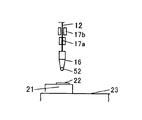
- the control unit 30 reads the overall control program, the wire cutting program, the wire extension program, and the control data stored in the storage unit 34 and stores them in the internal memory. Further, as shown in FIG. 2A, an initial ball 52 is formed at the tip of the capillary 16. In this state, the first clamper 17a is closed and the second clamper 17b is open.
- the control unit 30 outputs a command to move the tip of the capillary 16 directly above the pad 22 of the semiconductor chip 21.
- the command from the moving mechanism interface 44 is transmitted to the XY table 20, and the XY table 20 moves the position of the bonding head 19 so that the position of the capillary 16 is positioned just above the pad 22.
- the control unit 30 when the alignment is completed, the control unit 30 outputs a command to lower the capillary 16 to the pad 22.
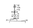
- a signal for driving the Z-direction motor of the bonding head 19 is output from the moving mechanism interface 44, and the Z-direction motor is rotated by this signal, the capillary 16 is lowered toward the pad 22, and the initial ball 52 is moved to the pad 22.
- the wire 12 is bonded and bonded to the pad 22 as a press-bonded ball 53.
- the control unit 30 outputs a command to open the first clamper 17a.
- the clamper opening / closing interface 41 outputs a signal for opening the first clamper 17a. By this signal, the first clamper 17a is opened by the first clamper opening / closing mechanism 27a.
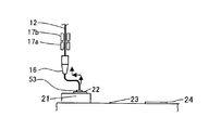
- the controller 30 raises the capillary 16 and then leads 24 and 24, as shown in FIG. 2C.
- a command to move horizontally in the opposite direction and further raise is output.
- the moving mechanism interface 44 drives the Z-direction motor of the bonding head 19 to raise the capillary 16 and the XY table 20 drives the tip of the capillary 16 to a position opposite to the lead 24.
- a signal is output.
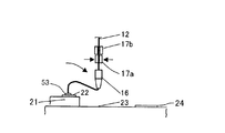
- the control unit 30 outputs a command for lowering the capillary 16 toward the lead 24 and a command for closing the first clamper 17a.
- the Z direction motor of the bonding head 19 and the XY table 20 are driven by these signals, and the capillary 16 is looped while descending toward the lead 24.
- a signal for closing the first clamper 17 a is output from the clamper opening / closing interface 41 according to a command from the control unit 30. By this signal, the first clamper 17a is closed by the first clamper opening / closing mechanism 27a.
- the control unit 30 outputs a command for further lowering the capillary 16 and bonding to the lead 24 when the capillary 16 comes on the lead 24.
- a signal for lowering the capillary 16 is output from the moving mechanism interface 44 by driving the Z-direction motor of the bonding head 19, and the Z-direction motor of the bonding head 19 is driven by this signal.
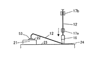
- the wire 12 is pressed against the lead 24 at the tip thereof, and the wire 12 is bonded to the lead 24 to be joined. From the start of the loop operation until the capillary 16 is bonded to the lead 24, the first clamper 17a remains closed and the second clamper 17b remains open.
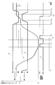
- FIG. 3 is a graph showing the open / close state of each clamper 17a, 17b, the height of the tip of the capillary 16, the on / off of the ultrasonic transducer 15 and the scrubbing state of the capillary 16 during bonding to the lead 24.
- the line a in the figure shows the open / close state of the first clamper 17a
- the line b shows the open / close state of the second clamper 17b
- the line z shows the change in the tip height of the capillary 16
- the line c shows the ultrasonic transducer.
- 15 indicates a change in the on / off state
- a line d indicates a change in the state of the scrubbing operation of the capillary 16.
- the capillary 16 to the time t 0 is starts the descent, the first clamper 17a is closed from the open. Then, the time t 1, the capillary 16 is in contact with the lead 24, the capillary 16 shown in FIG. 2E is bonded to the lead 24.
- the controller 30 presses the tip of the capillary 16 against the lead 24 and turns on the ultrasonic vibrator 15 to join the wire 12 and the lead 24 from time t 1 to time t 3 . Further, as shown in FIG. 2F, the control unit 30 moves the XY table 20 in the direction of the pad 22 and the lead 24 from the time t 1 to the time t 3 when the wire 12 is pressed against the lead 24 by the capillary 16.
- the scrubbing operation of the capillary 16 creates a minute crack between the portion of the wire 12 inserted through the capillary 16 and the joint portion of the lead 24, and the wire 12 can be easily cut.
- the scrubbing operation is not limited to the direction of the pad 22 and the lead 24, and may be reciprocated in any direction in the horizontal plane, and the capillary 16 may be moved in an arc shape or an ellipse shape. Alternatively, the capillary 16 may be simply moved laterally from the pad 22 toward the lead 24.
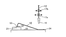
- the control unit 30 When it is time t 3 when 3, the control unit 30 as shown in FIG. 2G, and outputs a command to increase the tip end of the capillary 16 to a height H 1.
- a signal for driving the Z-direction motor of the bonding head 19 is output from the moving mechanism interface 44, and the Z-direction motor is driven based on this signal to raise the capillary 16.
- the first clamper 17a remains closed, and starts to rise together with the capillary 16 while holding the wire 12. Since the wire 12 is joined to the lead 24, an upward pulling force is applied to the wire 12 when the first clamper 17a is raised.
- the vicinity of the bonding portion of the wire 12 to the lead 24 is crushed by bonding and becomes narrower than the cross-sectional area of the wire 12, and the scrubbing operation of the capillary 16 causes the bonding portion between the wire 12 and the lead 24. Due to the occurrence of microcracks therebetween, the wire 12 is cut in the vicinity of the portion where the wire 12 is joined to the lead 24 of the wire 12 by tension (wire cutting step). At this time, as the wire 12 is more easily cut, the control unit 30, between t 5 from the time t 4 when 3 to vibrate the tip of the capillary 16 to the ultrasonic vibrator 15 as an on.
- the first clamper 17a when the capillary 16 is lifted from bonding to the lead 24 in the wire cutting step, the first clamper 17a is kept closed as shown in FIG. For this reason, even if the wire 12 is cut during bonding to the lead 24, the wire 12 does not come out of the capillary 16. However, since the wire is not cut after the tail wire 51 is extended to the tip of the capillary 16, the tail wire 51 is not extended to the tip of the capillary 16.
- the control unit 30 acquires the tip height of the signal of the capillary 16 acquired by the capillary height detecting means 29 through the capillary height detection interface 42 shown in FIG. 1, the height H 1 Compare with Then, the signal for stopping the Z-direction motor is outputted from the movement mechanism interface 44 Once the tip height of the capillary 16 is a H 1, to stop the rise of the capillary 16.
- the tip height of the capillary 16 to the time t 6 shown in FIG. 3 is a height H 1
- the control unit 30, the second clamper 17b outputs a command to close.
- a signal for closing the second clamper opening / closing mechanism 27b is output from the clamper opening / closing interface 41, and the second clamper opening / closing mechanism 27b is closed by this signal, the second clamper 17b is closed and the wire 12 is connected. Hold it.
- the control unit 30 outputs a command to open the first clamper 17a.
- an opening operation signal is output from the clamper opening / closing interface 41 to the first clamper opening / closing mechanism 27a.
- This opening operation signal causes the first clamper opening / closing mechanism 27a to open, thereby opening the first clamper 17a.
- the 1 clamper 17a releases the wire 12 that has been gripped.
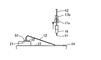
- the control unit 30 When the gripping clamper wire 12 is changed from the first clamper 17a to the second clamper 17b to the time t 8 as shown in FIG. 3, outputs a command to raise the tip height of the capillary 16 from H 1 of H 2 To do. With this command, the Z-direction motor of the bonding head 19 is driven, and the capillary 16 starts to rise. In this case, since the second clamper 17b is closed and holds the wire 12 in the height direction, the position in the height direction of the wire 12 does not change, and only the position of the capillary 16 and the first clamper 17a is H 1. It rises from up to H 2. As a result, the tail wire 51 is extended to the tip of the capillary 16 as shown in FIG. 2I.
- the control unit 30 vibrates the tip end of the capillary 16 turns on the ultrasonic vibrator 15 with raising the capillary 16, the wire 12 is smoothly the capillary 16 Try to pass through the hole.
- the control unit 30 is a tip height of the capillary 16 is detected by capillary height detecting means 29 outputs a command for stopping the increase of the capillary 16 to a moving mechanism interface 44 When turned its height the height H 2.
- the moving mechanism interface 44 outputs a signal for stopping the Z-direction motor, and this signal stops the Z-direction motor and stops raising the capillary 16.
- Capillary 16 is the tail wire 51 from the tip of the difference L by capillary 16 to the height H 1 and the height H 2 of FIG. 3 stops extending (wire extension means).
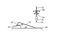
- a first clamper 17a After extended operation of the tail wire 51 is completed, the control unit 30, a first clamper 17a outputs a command to close the time t 10 shown in FIG. As shown in FIG. 2J, a signal for closing the first clamper 17a is output from the clamper opening / closing interface 41 by this command, and the first clamper 17a is closed by the first clamper opening / closing mechanism 27a by this signal. Then, the control unit 30 When the first clamper 17a becomes closed to the time t 11 shown in Fig. 3 outputs a command to open the second clamper 17b.
- a signal for opening the second clamper 17b is output from the clamper opening / closing interface 41, and the second clamper 17b is opened by the second clamper opening / closing mechanism 27b by this signal. Then, when the second clamper 17b to the time t 12 shown in FIG. 3 is gripped clamper wire 12 in the open is changed from the second clamper 17b to the first clamper 17a, the control unit 30 the capillary 16 by the moving mechanism 18 As shown in FIG. 2K, it is moved to the initial ball formation position, and the initial ball 52 is formed for the next wire bonding.
- the control unit 30 outputs a command to move the tip position of the capillary 16 to the initial ball formation position to the moving mechanism interface 44.
- the XY table 20 is driven by this command, and the tip position of the capillary 16 moves to the initial ball formation position.
- the control unit 30 outputs an initial ball formation command to the ball formation unit interface 45.
- the discharge torch 26 is driven, the tail wire 51 extending to the tip of the capillary 16 is heated, and an initial ball 52 is formed.
- the control unit 30 moves the capillary 16 onto the next pad 22 to perform the next bonding.
- the wire 12 since bonding is performed to the lead 24 with the first clamper 17a closed, the wire 12 does not come out of the capillary 16 even if the wire 12 breaks during bonding, and the wire is not pulled out. It can be effectively suppressed.
- the pressing force of the capillary 16 may be adjusted to such an extent that the wire can be cut by bonding. Even if the wire 12 cannot be cut during bonding, the wire in the vicinity of the bonding portion of the wire 12 to the lead 24 can be removed.
- the cross-sectional area can be further reduced by squeezing greatly, the repulsive force of the wire 12 when cutting the wire 12 can be suppressed smaller than in the prior art, and the wire 12 can be more effectively There is an effect that bending can be suppressed.
- the capillary 16 is scrubbed so that a minute crack is generated between the wire 12 and the joining portion so that the wire 12 is easily cut.
- the wire 12 is held by the first clamper 17a, and therefore, the scrubbing operation is not adjusted finely, so that the wire can be effectively removed. Can be suppressed.
- the bonding strength between the wire 12 and the lead 24 can be increased.
- the capillary 16 is scrubbed while the capillary 16 is pressed against the lead 24.
- bonding may be performed without performing the scrubbing operation of the capillary 16. Good.
- the wire 12 is cut after bonding to the lead 24.
- the initial ball 52 is bonded to the lead 24 and the wire 12 is cut after bonding to the pad 22. It can also be applied to bonding.
Landscapes
- Engineering & Computer Science (AREA)
- Mechanical Engineering (AREA)
- Wire Bonding (AREA)
Abstract
Description
Claims (4)
- ワイヤボンディング装置であって、
ワイヤが挿通され、ボンディング対象に前記ワイヤをボンディングするキャピラリと、
前記キャピラリと連動して移動する第1のクランパと、
前記キャピラリに挿通された前記ワイヤの伸びる方向に沿って前記第1のクランパと並べて配置される第2のクランパと、
前記第1クランパと前記第2のクランパとを開閉する制御部と、を備え、
前記制御部は、
前記キャピラリによって前記ワイヤをボンディングした後、前記第1クランパを閉じたまま前記キャピラリと前記第1クランパとを上昇させて前記ワイヤを切断するワイヤ切断手段と、
前記キャピラリを上昇させた後、前記第1クランパを開、前記第2クランパを閉とし、前記キャピラリと前記第1クランパとを上昇させて前記キャピラリ先端に前記ワイヤを延出するワイヤ延出手段と、を備えるワイヤボンディング装置。 - 請求項1に記載のワイヤボンディング装置であって、
前記ワイヤ切断手段は、
前記ワイヤをボンディングする際に前記キャピラリをスクラブ動作させること、
を特徴とするワイヤボンディング装置。 - ボンディング方法であって、
ワイヤが挿通され、ボンディング対象に前記ワイヤをボンディングするキャピラリと、前記キャピラリと連動して移動する第1のクランパと、前記キャピラリに挿通された前記ワイヤの伸びる方向に沿って前記第1のクランパと並べて配置される第2のクランパと、を備えるワイヤボンディング装置を準備する工程と、
前記キャピラリによって前記ワイヤをボンディングした後、前記第1クランパを閉じたまま前記キャピラリと前記第1クランパとを上昇させて前記ワイヤを切断するワイヤ切断工程と、
前記キャピラリを上昇させた後、前記第1クランパを開、前記第2クランパを閉とし、前記キャピラリと前記第1クランパとを上昇させて前記キャピラリ先端に前記ワイヤを延出するワイヤ延出工程と、を備えるボンディング方法。 - 請求項3に記載のボンディング方法であって、
ワイヤ切断工程は、
前記ワイヤをボンディングする際に前記キャピラリをスクラブ動作させるボンディング方法。
Priority Applications (4)
| Application Number | Priority Date | Filing Date | Title |
|---|---|---|---|
| KR1020117018158A KR101087999B1 (ko) | 2009-01-07 | 2009-07-13 | 와이어 본딩 장치 및 본딩 방법 |
| CN2009801534840A CN102272911B (zh) | 2009-01-07 | 2009-07-13 | 引线焊接装置及焊接方法 |
| SG2011049756A SG172906A1 (en) | 2009-01-07 | 2009-07-13 | Wire bonding apparatus and wire bonding method |
| US13/177,749 US8191759B2 (en) | 2009-01-07 | 2011-07-07 | Wire bonding apparatus and wire bonding method |
Applications Claiming Priority (2)
| Application Number | Priority Date | Filing Date | Title |
|---|---|---|---|
| JP2009-001961 | 2009-01-07 | ||
| JP2009001961A JP4467631B1 (ja) | 2009-01-07 | 2009-01-07 | ワイヤボンディング方法 |
Related Child Applications (1)
| Application Number | Title | Priority Date | Filing Date |
|---|---|---|---|
| US13/177,749 Continuation US8191759B2 (en) | 2009-01-07 | 2011-07-07 | Wire bonding apparatus and wire bonding method |
Publications (1)
| Publication Number | Publication Date |
|---|---|
| WO2010079633A1 true WO2010079633A1 (ja) | 2010-07-15 |
Family
ID=42306593
Family Applications (1)
| Application Number | Title | Priority Date | Filing Date |
|---|---|---|---|
| PCT/JP2009/062688 Ceased WO2010079633A1 (ja) | 2009-01-07 | 2009-07-13 | ワイヤボンディング装置及びボンディング方法 |
Country Status (6)
| Country | Link |
|---|---|
| US (1) | US8191759B2 (ja) |
| JP (1) | JP4467631B1 (ja) |
| KR (1) | KR101087999B1 (ja) |
| CN (1) | CN102272911B (ja) |
| SG (1) | SG172906A1 (ja) |
| WO (1) | WO2010079633A1 (ja) |
Families Citing this family (19)
| Publication number | Priority date | Publication date | Assignee | Title |
|---|---|---|---|---|
| CN103069557B (zh) * | 2010-08-10 | 2015-12-02 | 库力索法工业公司 | 引线环、形成引线环的方法及相关处理 |
| JP5662227B2 (ja) * | 2011-04-05 | 2015-01-28 | 株式会社新川 | ボンディング装置及びボンディングツールの洗浄方法 |
| CN103107111B (zh) * | 2011-11-11 | 2017-03-01 | 飞思卡尔半导体公司 | 用于监测线接合中无空气球(fab)形成的方法和装置 |
| US9314869B2 (en) * | 2012-01-13 | 2016-04-19 | Asm Technology Singapore Pte. Ltd. | Method of recovering a bonding apparatus from a bonding failure |
| JP2015114242A (ja) * | 2013-12-12 | 2015-06-22 | 株式会社新川 | ワイヤボンディングの検査方法及びワイヤボンディングの検査装置 |
| JP5686912B1 (ja) * | 2014-02-20 | 2015-03-18 | 株式会社新川 | バンプ形成方法、バンプ形成装置及び半導体装置の製造方法 |
| SG10201400485PA (en) * | 2014-03-07 | 2015-10-29 | Kande Private Ltd | A wire holding apparatus for wire bonding |
| US11302669B2 (en) | 2015-10-15 | 2022-04-12 | Skyworks Solutions, Inc. | Wire bond cleaning method and wire bonding recovery process |
| US20180151532A1 (en) * | 2015-12-25 | 2018-05-31 | Kaijo Corporation | Wire bonding apparatus |
| TWI668773B (zh) | 2017-03-16 | 2019-08-11 | Shinkawa Ltd. | 引線接合裝置和半導體裝置的製造方法 |
| CN109702335B (zh) * | 2017-10-25 | 2020-11-13 | 泰科电子(上海)有限公司 | 焊接系统 |
| CN110943011B (zh) * | 2019-11-21 | 2024-08-20 | 深圳市德沃先进自动化有限公司 | 一种键合设备用的质量监测控制器及其集总控制方法 |
| CN110828412B (zh) * | 2019-12-04 | 2025-04-04 | 武汉飞恩微电子有限公司 | 一种铜覆铝的键合插针及其键合装置 |
| KR102793253B1 (ko) * | 2020-05-14 | 2025-04-08 | 삼성전자주식회사 | 반도체 패키지의 와이어 본딩 방법 |
| WO2022049721A1 (ja) | 2020-09-04 | 2022-03-10 | 株式会社新川 | ワイヤボンディング装置、クランプ装置の開き量の測定方法、及び、クランプ装置の校正方法 |
| CN116250067A (zh) * | 2020-11-25 | 2023-06-09 | 株式会社新川 | 打线形成方法以及半导体装置的制造方法 |
| TWI775430B (zh) * | 2021-05-11 | 2022-08-21 | 日商新川股份有限公司 | 半導體裝置的製造方法以及打線接合裝置 |
| KR102818141B1 (ko) * | 2021-06-07 | 2025-06-11 | 가부시키가이샤 신가와 | 반도체 장치의 제조 방법 및 와이어 본딩 장치 |
| CN116748659A (zh) * | 2023-05-06 | 2023-09-15 | 深圳市华尚半导体科技有限公司 | 焊线方法、焊线机构及焊线设备 |
Citations (3)
| Publication number | Priority date | Publication date | Assignee | Title |
|---|---|---|---|---|
| JPS6211242A (ja) * | 1986-06-27 | 1987-01-20 | Hitachi Ltd | ワイヤボンデイング装置 |
| JPH06132344A (ja) * | 1992-10-21 | 1994-05-13 | Toshiba Corp | ワイヤボンディング装置 |
| JP2007180348A (ja) * | 2005-12-28 | 2007-07-12 | Shinkawa Ltd | ワイヤボンディング装置、ボンディング制御プログラム及びボンディング方法 |
Family Cites Families (16)
| Publication number | Priority date | Publication date | Assignee | Title |
|---|---|---|---|---|
| JPS58131744A (ja) | 1982-01-29 | 1983-08-05 | Shinkawa Ltd | ワイヤボンダにおけるキヤピラリへのワイヤ通し方法 |
| JPS6435500A (en) | 1987-07-30 | 1989-02-06 | Hitachi Heating Appl | Voice recognition |
| JP2723277B2 (ja) | 1989-01-30 | 1998-03-09 | 株式会社東芝 | ワイヤボンディング方法 |
| JP2530224B2 (ja) | 1989-05-15 | 1996-09-04 | 株式会社新川 | ワイヤボンデイング方法 |
| JP2969953B2 (ja) | 1990-12-17 | 1999-11-02 | 富士通株式会社 | 半導体装置の製造方法及びその装置 |
| JPH04372146A (ja) * | 1991-06-21 | 1992-12-25 | Toshiba Corp | ワイヤボンディング装置 |
| JP3128718B2 (ja) | 1993-09-21 | 2001-01-29 | 株式会社新川 | ワイヤボンデイング方法 |
| JP3077101B2 (ja) * | 1995-11-24 | 2000-08-14 | 株式会社新川 | 被覆ワイヤのワイヤボンディング装置及びその方法 |
| JP3074518B2 (ja) * | 1995-12-05 | 2000-08-07 | 株式会社新川 | 被覆ワイヤのワイヤボンディング方法 |
| JP3074517B2 (ja) * | 1995-12-05 | 2000-08-07 | 株式会社新川 | 被覆ワイヤのワイヤボンディング方法 |
| JPH09252005A (ja) * | 1996-03-15 | 1997-09-22 | Shinkawa Ltd | バンプ形成方法 |
| JP3566156B2 (ja) * | 1999-12-02 | 2004-09-15 | 株式会社新川 | ピン状ワイヤ等の形成方法 |
| JP4088015B2 (ja) * | 2000-03-24 | 2008-05-21 | 株式会社新川 | 湾曲状ワイヤの形成方法 |
| JP4509043B2 (ja) * | 2006-02-14 | 2010-07-21 | 株式会社新川 | スタッドバンプの形成方法 |
| JP4679427B2 (ja) * | 2006-04-24 | 2011-04-27 | 株式会社新川 | ボンディング装置のテールワイヤ切断方法及びプログラム |
| JP4700570B2 (ja) * | 2006-07-14 | 2011-06-15 | 株式会社新川 | ボンディング装置並びにボンディングツール先端部の洗浄方法及びプログラム |
-
2009
- 2009-01-07 JP JP2009001961A patent/JP4467631B1/ja active Active
- 2009-07-13 CN CN2009801534840A patent/CN102272911B/zh active Active
- 2009-07-13 SG SG2011049756A patent/SG172906A1/en unknown
- 2009-07-13 WO PCT/JP2009/062688 patent/WO2010079633A1/ja not_active Ceased
- 2009-07-13 KR KR1020117018158A patent/KR101087999B1/ko active Active
-
2011
- 2011-07-07 US US13/177,749 patent/US8191759B2/en active Active
Patent Citations (3)
| Publication number | Priority date | Publication date | Assignee | Title |
|---|---|---|---|---|
| JPS6211242A (ja) * | 1986-06-27 | 1987-01-20 | Hitachi Ltd | ワイヤボンデイング装置 |
| JPH06132344A (ja) * | 1992-10-21 | 1994-05-13 | Toshiba Corp | ワイヤボンディング装置 |
| JP2007180348A (ja) * | 2005-12-28 | 2007-07-12 | Shinkawa Ltd | ワイヤボンディング装置、ボンディング制御プログラム及びボンディング方法 |
Also Published As
| Publication number | Publication date |
|---|---|
| JP2010161176A (ja) | 2010-07-22 |
| US20110278349A1 (en) | 2011-11-17 |
| CN102272911B (zh) | 2013-11-06 |
| KR20110094227A (ko) | 2011-08-22 |
| SG172906A1 (en) | 2011-08-29 |
| CN102272911A (zh) | 2011-12-07 |
| JP4467631B1 (ja) | 2010-05-26 |
| KR101087999B1 (ko) | 2011-12-01 |
| US8191759B2 (en) | 2012-06-05 |
Similar Documents
| Publication | Publication Date | Title |
|---|---|---|
| JP4467631B1 (ja) | ワイヤボンディング方法 | |
| US7658314B2 (en) | Tail wire cutting method and bonding apparatus | |
| JP4787374B2 (ja) | 半導体装置の製造方法並びにワイヤボンディング装置 | |
| KR101086667B1 (ko) | 와이어 본딩 장치 및 방법 | |
| CN104813457B (zh) | 打线装置以及打线方法 | |
| CN103069557B (zh) | 引线环、形成引线环的方法及相关处理 | |
| WO2015125671A1 (ja) | 半導体装置の製造方法及びワイヤボンディング装置 | |
| JP4658224B2 (ja) | ワイヤボンディング装置 | |
| US9887174B2 (en) | Semiconductor device manufacturing method, semiconductor device, and wire bonding apparatus | |
| JP7416491B2 (ja) | ワイヤボンディング装置、ワイヤ切断方法及びプログラム | |
| KR102411252B1 (ko) | 와이어 본딩 장치 | |
| JP4365851B2 (ja) | ワイヤボンディング方法及びワイヤボンディング装置 | |
| CN106233444A (zh) | 半导体装置的制造方法以及打线装置 | |
| TWI902269B (zh) | 打線接合裝置及修復方法 | |
| TWI901206B (zh) | 打線接合裝置 | |
| KR100413477B1 (ko) | 와이어 본더의 본더헤드 | |
| TW202326891A (zh) | 打線接合裝置、打線切斷方法以及程式 | |
| TWI529831B (zh) | 打線裝置以及打線方法 |
Legal Events
| Date | Code | Title | Description |
|---|---|---|---|
| WWE | Wipo information: entry into national phase |
Ref document number: 200980153484.0 Country of ref document: CN |
|
| 121 | Ep: the epo has been informed by wipo that ep was designated in this application |
Ref document number: 09837519 Country of ref document: EP Kind code of ref document: A1 |
|
| NENP | Non-entry into the national phase |
Ref country code: DE |
|
| ENP | Entry into the national phase |
Ref document number: 20117018158 Country of ref document: KR Kind code of ref document: A |
|
| 122 | Ep: pct application non-entry in european phase |
Ref document number: 09837519 Country of ref document: EP Kind code of ref document: A1 |