WO2010077100A2 - 이차전지용 음극 활물질 - Google Patents
이차전지용 음극 활물질 Download PDFInfo
- Publication number
- WO2010077100A2 WO2010077100A2 PCT/KR2009/007985 KR2009007985W WO2010077100A2 WO 2010077100 A2 WO2010077100 A2 WO 2010077100A2 KR 2009007985 W KR2009007985 W KR 2009007985W WO 2010077100 A2 WO2010077100 A2 WO 2010077100A2
- Authority
- WO
- WIPO (PCT)
- Prior art keywords
- metal
- active material
- phase
- negative electrode
- electrode active
- Prior art date
Links
Images
Classifications
-
- H—ELECTRICITY
- H01—ELECTRIC ELEMENTS
- H01M—PROCESSES OR MEANS, e.g. BATTERIES, FOR THE DIRECT CONVERSION OF CHEMICAL ENERGY INTO ELECTRICAL ENERGY
- H01M4/00—Electrodes
- H01M4/02—Electrodes composed of, or comprising, active material
- H01M4/13—Electrodes for accumulators with non-aqueous electrolyte, e.g. for lithium-accumulators; Processes of manufacture thereof
- H01M4/134—Electrodes based on metals, Si or alloys
-
- H—ELECTRICITY
- H01—ELECTRIC ELEMENTS
- H01M—PROCESSES OR MEANS, e.g. BATTERIES, FOR THE DIRECT CONVERSION OF CHEMICAL ENERGY INTO ELECTRICAL ENERGY
- H01M10/00—Secondary cells; Manufacture thereof
- H01M10/05—Accumulators with non-aqueous electrolyte
- H01M10/052—Li-accumulators
-
- H—ELECTRICITY
- H01—ELECTRIC ELEMENTS
- H01M—PROCESSES OR MEANS, e.g. BATTERIES, FOR THE DIRECT CONVERSION OF CHEMICAL ENERGY INTO ELECTRICAL ENERGY
- H01M10/00—Secondary cells; Manufacture thereof
- H01M10/05—Accumulators with non-aqueous electrolyte
- H01M10/052—Li-accumulators
- H01M10/0525—Rocking-chair batteries, i.e. batteries with lithium insertion or intercalation in both electrodes; Lithium-ion batteries
-
- H—ELECTRICITY
- H01—ELECTRIC ELEMENTS
- H01M—PROCESSES OR MEANS, e.g. BATTERIES, FOR THE DIRECT CONVERSION OF CHEMICAL ENERGY INTO ELECTRICAL ENERGY
- H01M4/00—Electrodes
- H01M4/02—Electrodes composed of, or comprising, active material
-
- H—ELECTRICITY
- H01—ELECTRIC ELEMENTS
- H01M—PROCESSES OR MEANS, e.g. BATTERIES, FOR THE DIRECT CONVERSION OF CHEMICAL ENERGY INTO ELECTRICAL ENERGY
- H01M4/00—Electrodes
- H01M4/02—Electrodes composed of, or comprising, active material
- H01M4/36—Selection of substances as active materials, active masses, active liquids
- H01M4/38—Selection of substances as active materials, active masses, active liquids of elements or alloys
- H01M4/386—Silicon or alloys based on silicon
-
- Y—GENERAL TAGGING OF NEW TECHNOLOGICAL DEVELOPMENTS; GENERAL TAGGING OF CROSS-SECTIONAL TECHNOLOGIES SPANNING OVER SEVERAL SECTIONS OF THE IPC; TECHNICAL SUBJECTS COVERED BY FORMER USPC CROSS-REFERENCE ART COLLECTIONS [XRACs] AND DIGESTS
- Y02—TECHNOLOGIES OR APPLICATIONS FOR MITIGATION OR ADAPTATION AGAINST CLIMATE CHANGE
- Y02E—REDUCTION OF GREENHOUSE GAS [GHG] EMISSIONS, RELATED TO ENERGY GENERATION, TRANSMISSION OR DISTRIBUTION
- Y02E60/00—Enabling technologies; Technologies with a potential or indirect contribution to GHG emissions mitigation
- Y02E60/10—Energy storage using batteries
Definitions
- the present invention relates to a negative electrode active material for secondary batteries having excellent cycle characteristics, small volume expansion, and high capacity.
- the lithium secondary battery currently used uses a carbon-based material as a negative electrode active material.
- the carbon-based material has a theoretical capacity of 372 mAh / g, and is used at a capacity of about 360 mAh / g which is almost close to the theoretical capacity in commercially available batteries. It is reaching the limit. Therefore, in order to manufacture a high capacity battery, development of a new material that can replace the carbon-based negative electrode active material is essential.
- Representative materials of the new high capacity negative electrode active material include metal materials such as silicon (Si) and tin (Sn) that can occlude / discharge lithium by alloying with lithium (Li).
- metal materials such as silicon (Si) and tin (Sn) that can occlude / discharge lithium by alloying with lithium (Li).
- Si silicon
- Sn tin
- the volume change during charging / discharging reaches 300-400%, resulting in separation from the electrode and severely deteriorating cycle characteristics. There was a problem such as being difficult to apply to the battery actually.
- alloy-type materials Si-M alloy, Sn-M alloy, M is a metal element of silicon (Si), tin (Sn) and other metals have been studied by many researchers. .
- These alloy-type materials include single element phases, such as silicon (Si) and tin (Sn), which can be combined with lithium, and metal siliside (M x Si y ) phases, which are not bonded with lithium, and tin. It is known that an alloy (metal Sn alloy, M x Sn y ) phase or the like is formed.
- a single phase such as silicon (Si) and tin (Sn) may be combined with and detached from lithium during charging / discharging, thereby realizing a battery capacity according to the electrochemical reaction of the battery, and metal siliside,
- the M x Si y ) phase, the metal Sn alloy, and the M x Sn y phase do not combine with lithium and suppress the volume change of a single phase such as silicon (Si) and tin (Sn), thereby reducing the volume of the negative electrode active material. It is known to play a role in suppressing volume expansion.
- the phase constituting the negative electrode active material is divided into a phase mainly composed of Si and a phase mainly composed of an alloy of Si-metal, and the ratio of these phases is adjusted (Japanese Patent Laid-Open No. 2006-164960), or these phases By adjusting the particle size (Japanese Patent No. 4344121, Korean Patent No. 917199), the capacitance and cycle characteristics were adjusted.
- the Si phase and the Si-metal alloy phase have been controlled to control their ratios.
- the Si phase and Si-metal alloy phase that make up the material are both crystalline and amorphous. None reported.
- the present inventors found that an alloy of Si-metal used to suppress volume expansion as a negative electrode active material exists in a crystalline state in addition to an amorphous state, and the Si single phase which is separate from the alloy phase of Si-metal has a capacitance even when it is amorphous.
- the present invention has been found to contribute to the implementation.
- Si used to realize capacitance is known to exist only as a crystalline phase or an amorphous phase is considered to not implement capacitance because it is composed of a Si-metal alloy. Therefore, in order to improve the capacitive and cycle characteristics of the battery, conventionally, a method of controlling the ratio of the Si phase and the Si-metal alloy phase or controlling the particle size of the phase is used to control the ratio of the entire crystalline phase and the amorphous phase. I never tried to. However, according to the research results of the present inventors, such a method could not sufficiently improve the capacitance characteristics and the cycle characteristics because the Si present in the amorphous phase contributes to the realization of the capacitance.
- the present invention provides a negative electrode active material comprising a crystalline phase comprising Si and a Si-metal alloy, and an amorphous phase comprising Si and a Si-metal alloy, and a Si-metal constituting the amorphous phase and the Si-metal alloy constituting the crystalline phase. Alloys provide a negative electrode active material, the metal constituting the alloy may be the same or different from each other.
- the present invention also provides an electrode including the negative electrode active material and a lithium secondary battery including the electrode.
- the present invention also provides an electrode including the negative electrode active material and the negative electrode active material made of a carbon material, and a lithium secondary battery comprising the electrode.
- the present invention provides a negative electrode active material including a crystalline phase including Si and a Si-metal alloy, and an amorphous phase including Si and a Si-metal alloy.
- the Si-metal alloy constituting the crystalline phase and the Si-metal alloy constituting the amorphous phase may be the same as or different from each other. It is preferable that the metals which comprise an alloy are the same as each other.
- the metal may be one, two, or more. It is preferable to use 2 or more types. That is, the alloy may be in the form of Si-A, in the form of Si-A-B, in the form of Si-A-B-C, and the like (where A, B, and C represent different metals).
- Metals used include Ca, Sc, Ti, V, Cr, Mn, Fe, Co, Ni, Cu, Zn, Sr, Y, Zr, Nb, Ba, Lu, Hf, Ta, and lanthanide elements.
- Ca, Co, Ni, Mn, Ti, Zr, Co, Ni, Fe, rare earth elements (Sc, Y, lanthanide elements) can be preferably used.
- an alloy of the Si-A type that is, when using one kind of metal in addition to Si, it is particularly preferable to use a metal selected from Co, Ni, Mn, Ti.
- an alloy of the Si-AB type that is, when using two kinds of metals in addition to Si, one type of metal selected from Ti and Zr as A, and one type selected from Co, Ni and Fe as B Particular preference is given to using.
- one or more metals selected from rare earth elements and one metal selected from Co, Ni, and Fe may be mixed and used.
- a mixed rare-earth element preferably a misch metal, may be used as the rare earth element.
- the negative electrode active material of the present invention is composed of a material in which the crystalline phase and the amorphous phase are mixed. Both the crystalline phase and the amorphous phase are composed of a material which can be repeatedly inserted and detached with Li electrochemically and a material that cannot be bonded with Li electrochemically.
- the crystalline phase in the present invention includes an alloy of Si and Si-metal. Other metals may also be present in this crystalline phase.
- the amorphous phase includes an alloy of Si and Si-metal. Other metals may also be present in this amorphous phase.
- both Si and Si-metal alloys are present in the crystalline phase and the amorphous phase, and the two phases are mixed to control the ratio of these two phases to maximize the volume expansion and cycle characteristics of the battery.
- the ratio between the crystalline phase and the amorphous phase can be controlled by the type and amount of metal selected during production, the method of producing the alloy, and the like.
- the amount of amorphous phase can be controlled through ball milling, which is mechanical alloying.
- the amount of the amorphous phase can be increased by selecting a composition that readily forms the amorphous phase, increasing the cooling rate during quenching, or increasing the ball milling time, the ratio of the ball to the alloy, the linear speed of the mill, and the like.
- the content of the amorphous phase is preferably 30% by weight or more based on the entire crystalline phase and the amorphous phase. The higher the content of the amorphous phase, the more preferred.
- the raw material for producing the negative electrode active material in the present invention is not particularly limited as long as it can implement the composition ratio required for the negative electrode active material.
- an element, an alloy, a solid solution, an intermetallic compound, or the like can be used to mix the elements constituting the negative electrode active material in a desired composition ratio.
- the method for producing the negative electrode active material is not particularly limited as long as it can produce a phase in which the crystalline phase and the amorphous phase are uniformly mixed.
- Melt spinning, strip casting, atomizing, etc. which melt and then rapidly cool the composition containing Si, may be used.
- Direct casting rolling, spray foaming, gas spraying, and wet spraying may also be used.
- the alloy prepared in this manner is pulverized to prepare a metal powder containing Si.
- the metal powder is ground using a mechanical method to prepare a negative electrode active material.
- the particle size is preferably 1 ⁇ m to 50 ⁇ m.
- the prepared alloy phase may be treated by mechanical alloying to produce a negative electrode active material having a desired ratio of crystalline phase / amorphous phase.
- the present invention also provides an electrode including the negative electrode active material and a lithium secondary battery including the electrode.
- the present invention also provides an electrode including the negative electrode active material and the negative electrode active material made of a carbon material, and a lithium secondary battery comprising the electrode.
- An electrode may be manufactured using the prepared negative active material.
- the electrode is prepared by mixing a metal powder, a conductive agent and a binder.
- PVdF may be used as the binder, but other types of binder may be used as long as the electrode can be formed.
- polyethylene, polyprolylene, polytetrafluoro ethylene, styrene butadiene rubber, or the like may be used.
- the binder is dissolved in a solvent such as NMP, and then a metal powder and a conductive agent are put together to prepare a slurry uniformly.
- a solvent such as NMP
- Acetylene black may be used as the conductive agent, but artificial graphite, carbon fiber, carbon nanotubes (CNT), and amorphous carbon may be used as long as the conductivity of the electrode can be sufficiently secured.
- the Rietveld refinement method by X-ray diffraction analysis which is a conventionally known method, is used to accurately determine how much amorphous amount is present. It is difficult. Rietveld analysis method can accurately measure the ratio of the crystalline phase, but it is difficult to calculate the ratio of the amorphous phase.
- the Rietveld analysis method by X-ray diffraction analysis is performed to calculate the volume ratio of each phase, and then the data is used as the standard A method of converting based on the amount of mixture of materials is used. This method is called a spike method in the present invention.
- the amount of Si in the alloy is 36.5% by weight, and based on the calculation of the capacitance, the capacity of 1315mAh / g is calculated.
- the value was 1100mAh / g, which is much smaller than the theoretical value. This means that the simple XRD Rietveld method cannot accurately determine the amount of Si participating in the reaction.
- the amount of Si in the alloy containing MgO was 16.3% by weight and the amount of amorphous phase was 37.3% by weight. Removing MgO, a standard, and converting it as a percentage, the amount of Si is 20.4% by weight and the amount of amorphous phase is 46.6% by weight.
- the capacitance was calculated based on the amount of Si calculated by the Spike method of 20.4 wt%, it was 735 mAh / g, which was 365 mAh / g less than the actual test result of 1100 mAh / g. It means that Si is included to contribute to showing the capacitance.
- an electrode having excellent cycle characteristics, small volume expansion, and relatively excellent capacitance can be manufactured.
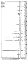
- FIG. 1 is a graph of Si-Ni-Ti alloys prepared (components, weight ratios, and manufacturing methods mentioned in Example 1), followed by XRD Rietveld method.
- Figure 3 shows the cycle characteristics of Example 1-5 and Comparative Example 1 graphically.
- Si, Ni, Ti were mixed in a weight ratio of 60: 5: 35, and then metal ribbons were manufactured by using a melt spinning method. Melt spinning was performed using a carbon crucible under an inert atmosphere in which argon gas was injected and not oxidized. The prepared metal ribbon was pulverized by hand in a mortar to prepare a metal powder, and sieved to have a particle size of 38 ⁇ m or less.
- the Spike method was used to accurately analyze the ratio between crystalline and amorphous phases.
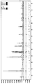
- 20% MgO was mixed with the metal powder prepared above, and mixed uniformly in a mortar and pestle, and XRD measurement was performed in the same manner as the method used for phase analysis of the metal powder. Thereafter, Rietveld analysis was performed to accurately determine the fraction of the crystalline phase and the MgO present in the material, and then the fraction of the amorphous phase was obtained therefrom.
- An electrode was prepared using the negative electrode active material prepared above.
- the electrode was prepared by mixing a metal powder, a conductive agent and a binder. PVdF was used as the binder. After dissolving PVdF in NMP, a metal powder and a conductive agent were put together to prepare a slurry. At this time, acetylene black was used as the conductive agent. The weight ratio of the metal powder, the conductive agent, and the binder, which is each component in the electrode slurry, is 80:10:10. The prepared slurry was well coated on copper foil and then dried at 130 ° C. for 4 hours in a vacuum atmosphere.
- a coin half cell was prepared using the prepared electrode and metal Li.
- the electrolyte used in the manufacture of the coin cell contains ethylene carbonate and diethyl carbonate in a 3: 7 ratio and 1 mole of LiPF6 is dissolved.
- a separator was inserted between the metal Li and the electrode.
- the coin cell was decomposed and the thickness was measured, and the degree of expansion from the initial thickness was measured.
- Ball milling was performed to adjust the ratio of the crystalline phase and the amorphous phase of the metal powder prepared in Example 1 (using SPEX MILL 8000). Ball milling is carried out for 30 hours (Example 2), 60 hours (Example 3), 90 hours (Example 4), 120 hours (after carrying out the stainless steel metal ball and the metal powder in a weight ratio of 15: 1 in a stainless steel metal container). Example 5). When ball milling, argon was injected into the stainless steel container and ball milling was performed in an inert atmosphere.
- Example 2 XRD analysis was conducted in the same manner as in Example 1 to analyze the crystal structure after ball milling.
- a coin half cell was prepared in the same manner as in Example 1 to evaluate the performance of the battery.
- a metal mass was prepared in the same manner as in Example 1-5 except that the metal material was melted using the melt spinning method and then slowly cooled in air.
- the prepared metal mass was pulverized using mortar and balls.
- the pulverized metal powder was used after filtering to have a particle size of 38 ⁇ m or less.
- the prepared metal mass showed a relatively higher proportion of the crystalline phase than in Example 1-5.
- the phase was analyzed in the same manner as in Example 1, and the performance of the battery was evaluated.
- Table 3 shows the results of analyzing the phases in Example 1-5 and Comparative Example 1 and evaluating the performance of the battery.
- the amount of crystalline and amorphous was divided by the spike method, and in the case of Example 1, the results of the spike analysis were described above.
- Example 1-5 the amorphous phase accounted for 40% or more.
- the capacitance is more than twice as good as the 360 mAh / g of the carbon-based material (816 to 843 mAh / g), the capacity retention rate (60 to 75%) after 50 cycles is also high and the volume expansion (182 to 257) %) was also less.
- the capacitance decreased (843 mAh / g-> 816 mAh / g), but after 50 cycles, the capacity retention improved from 60% to 75%, and the volume expansion rate It was reduced from 257% to 182% and shown to have excellent overall performance.
- Comparative Example 1 prepared by slow cooling, the proportion of the amorphous phase was 15%, and the ratio of the crystalline phase was 85%.
- the capacity was excellent at 875mAh / g, but after 50 cycles, the capacity retention rate was very low at 5% and the volume expansion rate was very high at 370%.
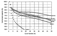
- Figure 3 shows the cycle characteristics of Example 1-5 and Comparative Example 1 graphically.
- 3 shows Examples 1-5 having a higher amorphous content compared to Comparative Example 1 having a higher crystalline content, and Example 2 than Example 1, and Examples 3 and 4 than Example 2 in Examples 1-5. , 5, that is, the more the amorphous content it can be seen that the cycle characteristics are excellent.
- a metal powder was prepared in the same manner as in Example 1, except that Si and Co were mixed at a weight ratio of 63:37 (Example 6).
- a metal powder was prepared by ball milling the prepared Si-Co alloy in the same manner as in Example 2-5 (Example 7-10). Thereafter, the phases were analyzed in the same manner as in Example 1, and the performance of the battery was evaluated.
- a metal powder was prepared in the same manner as in Comparative Example 1 except that Si and Co were mixed at a weight ratio of 63:37, the phases were analyzed, and the performance of the battery was evaluated.
- a metal powder was prepared in the same manner as in Example 1 except that Si and Ni were mixed in a weight ratio of 65:35 (Example 11). Ball milling was performed on the prepared Si-Co alloy in the same manner as in Example 2-5 to prepare a metal powder (Example 12-15).
- a metal powder was prepared in the same manner as in Comparative Example 1 except that Si and Ni were mixed at a weight ratio of 65:35, and after analyzing the phases, the performance of the battery was evaluated.
- a metal powder was prepared in the same manner as in Example 1 except that Si and Mn were mixed at a weight ratio of 61:39 (Example 16). Ball milling was performed on the prepared Si-Mn alloy in the same manner as in Example 2-5 to prepare a metal powder (Example 17-20). Thereafter, the phases were analyzed in the same manner as in Example 1, and the performance of the battery was evaluated.
- a metal powder was prepared in the same manner as in Comparative Example 1 except that Si and Mn were mixed at a weight ratio of 61:39, and the phases were analyzed. Then, the performance of the battery was evaluated.
- a metal powder was prepared in the same manner as in Example 1, except that Si, mish metal, and Ni were mixed at a weight ratio of 57:15:28 (Example 21). Ball milling was carried out in the same manner as in Example 2-5 to prepare a metal powder (Example 22-25). Thereafter, the phases were analyzed in the same manner as in Example 1, and the performance of the battery was evaluated.
- a metal powder was prepared in the same manner as in Comparative Example 1 except that Si, mish metal, and Ni were mixed at a weight ratio of 57: 15: 28%, and the phases were analyzed to evaluate battery performance.
- Example 6-25 and Comparative Example 2-5 The results of analyzing the phases in Example 6-25 and Comparative Example 2-5 and evaluating the performance of the battery are shown in Table 4 below.
- Example 4 Amorphous phase ratio Volume Capacity retention rate after 50 cycles (50 cycles discharge capacity / 1 cycle discharge capacity X 100) Thickness expansion rate when charging 50 cycles (thickness when charging 50 cycles / 1 thickness before charging cycles X 100)
- Example 6 38% 987 mAh / g 45% 296%
- Example 7 46% 976 mAh / g 51% 275%
- Example 8 49% 969 mAh / g 57% 266%
- Example 10 64% 961 mAh / g 64% 239% Comparative Example 2 7% 1054 mAh / g 9% 390%
- Example 11 32% 1375 mAh / g 44% 317%
- Example 12 41% 1327 mAh / g 47% 303%
- Example 14 55% 1275 mAh / g 57% 279%
- Example 15 1266 mAh / g 60% 265% Comparative
- Example 6-25 the proportion of the amorphous phase accounted for 30% or more.
- the capacitance was 2.5 times more excellent than the 360 mAh / g of the carbon-based material (913-1375 mAh / g), and the capacity retention rate (44-75%) after 50 cycles was also high and the volume expansion (198-317) was performed. %) was also less.
- the cycle characteristics are improved and volume expansion is suppressed.
- Comparative Example 2-5 the ratio of the amorphous phase was 4-27%, and the crystalline phase occupied the most.
- the capacity was excellent at 985 ⁇ 1458mAh / g, but after 50 cycles, the capacity retention rate was very low, 4 ⁇ 32%, and the volume expansion rate was 366 ⁇ 413%.
- a negative electrode active material was prepared in the same manner as in Example 1, except that the metal powder prepared in Example 1-25 was mixed with carbon in a weight ratio of 50:50, to prepare a battery, and then analyzed a phase and a battery. The performance of was evaluated.
- a negative electrode active material was prepared in the same manner as in Comparative Example 1 except that the metal powder prepared in Comparative Example 1-5 was mixed with carbon in a weight ratio of 50:50, and the phase was analyzed. Evaluated.
- Example 26-50 The results of analyzing the phases in Example 26-50 and Comparative Example 6-10 and evaluating the performance of the battery are shown in Table 5 below.
- Example 26-50 the capacitance was superior to that of 360 mAh / g of the carbonaceous material (585 to 865 mAh / g), the capacity retention after 50 cycles was high (49 to 83%), and the volume expansion was small (134 to 168). %).
- the cycle characteristics are improved and volume expansion is suppressed.
Landscapes
- Chemical & Material Sciences (AREA)
- Chemical Kinetics & Catalysis (AREA)
- Electrochemistry (AREA)
- General Chemical & Material Sciences (AREA)
- Engineering & Computer Science (AREA)
- Materials Engineering (AREA)
- Manufacturing & Machinery (AREA)
- Battery Electrode And Active Subsutance (AREA)
- Silicon Compounds (AREA)
- Secondary Cells (AREA)
Priority Applications (5)
| Application Number | Priority Date | Filing Date | Title |
|---|---|---|---|
| CN200980153607.0A CN102272983B (zh) | 2008-12-30 | 2009-12-30 | 二次电池用阴极活性材料 |
| JP2011544375A JP5761758B2 (ja) | 2008-12-30 | 2009-12-30 | 二次電池用アノード活物質 |
| US13/142,463 US8426065B2 (en) | 2008-12-30 | 2009-12-30 | Anode active material for secondary battery |
| EP09836421.9A EP2375476B1 (en) | 2008-12-30 | 2009-12-30 | Active anode substance for secondary battery |
| US13/845,916 US8758939B2 (en) | 2008-12-30 | 2013-03-18 | Anode active material for secondary battery |
Applications Claiming Priority (2)
| Application Number | Priority Date | Filing Date | Title |
|---|---|---|---|
| KR10-2008-0136721 | 2008-12-30 | ||
| KR20080136721 | 2008-12-30 |
Related Child Applications (2)
| Application Number | Title | Priority Date | Filing Date |
|---|---|---|---|
| US13/142,463 A-371-Of-International US8426065B2 (en) | 2008-12-30 | 2009-12-30 | Anode active material for secondary battery |
| US13/845,916 Continuation US8758939B2 (en) | 2008-12-30 | 2013-03-18 | Anode active material for secondary battery |
Publications (2)
| Publication Number | Publication Date |
|---|---|
| WO2010077100A2 true WO2010077100A2 (ko) | 2010-07-08 |
| WO2010077100A3 WO2010077100A3 (ko) | 2010-10-21 |
Family
ID=42310413
Family Applications (1)
| Application Number | Title | Priority Date | Filing Date |
|---|---|---|---|
| PCT/KR2009/007985 WO2010077100A2 (ko) | 2008-12-30 | 2009-12-30 | 이차전지용 음극 활물질 |
Country Status (6)
| Country | Link |
|---|---|
| US (2) | US8426065B2 (zh) |
| EP (1) | EP2375476B1 (zh) |
| JP (1) | JP5761758B2 (zh) |
| KR (1) | KR101050352B1 (zh) |
| CN (1) | CN102272983B (zh) |
| WO (1) | WO2010077100A2 (zh) |
Cited By (2)
| Publication number | Priority date | Publication date | Assignee | Title |
|---|---|---|---|---|
| US20130149594A1 (en) * | 2011-12-13 | 2013-06-13 | Changui Jeong | Negative electrode active material and secondary battery including the same |
| US20130202967A1 (en) * | 2012-02-07 | 2013-08-08 | Jae-Hyuk Kim | Negative active material for rechargeable lithium battery and rechargeable lithium battery including same |
Families Citing this family (17)
| Publication number | Priority date | Publication date | Assignee | Title |
|---|---|---|---|---|
| KR101263265B1 (ko) * | 2010-07-30 | 2013-05-10 | 일진전기 주식회사 | 음극 활물질 |
| US9293235B2 (en) * | 2010-08-31 | 2016-03-22 | Toda Kogyo Corporation | Lithium titanate particles and process for producing the lithium titanate particles, Mg-containing lithium titanate particles and process for producing the Mg-containing lithium titanate particles, negative electrode active substance particles for non-aqueous electrolyte secondary batteries, and non-aqueous electrolyte secondary battery |
| KR101423652B1 (ko) * | 2011-10-18 | 2014-07-29 | 엠케이전자 주식회사 | 이차 전지용 음극 활물질 및 그 제조 방법 |
| KR101385602B1 (ko) * | 2011-12-14 | 2014-04-21 | 엠케이전자 주식회사 | 이차 전지용 음극 활물질 및 그 제조 방법 |
| KR101403498B1 (ko) * | 2012-01-31 | 2014-06-11 | 엠케이전자 주식회사 | 이차 전지용 음극 활물질 및 이를 포함하는 이차 전지 |
| JP2013187016A (ja) * | 2012-03-07 | 2013-09-19 | Hitachi Chemical Co Ltd | 複合材料、複合材料の製造方法、リチウムイオン二次電池用負極、及びリチウムイオン二次電池 |
| KR101914070B1 (ko) * | 2012-09-28 | 2018-11-01 | 인제대학교 산학협력단 | 리튬 2차 전지 음극 활물질용 Si 합금-형상 기억 합금 복합체의 제조 방법 및 이에 의하여 제조된 리튬 2차 전지 음극 활물질용 Si합금-형상 기억 합금 복합체 |
| KR101490559B1 (ko) * | 2012-12-12 | 2015-02-06 | 일진전기 주식회사 | 음극활물질용 복합금속 제조방법 |
| US20140203207A1 (en) * | 2013-01-22 | 2014-07-24 | Mk Electron Co., Ltd. | Anode active material for secondary battery and method of manufacturing the same |
| KR20150006703A (ko) * | 2013-07-09 | 2015-01-19 | 삼성정밀화학 주식회사 | 리튬이차전지용 음극 활물질, 이를 포함하는 음극용 조성물 및 리튬이차전지 |
| JP6138960B2 (ja) * | 2013-10-31 | 2017-05-31 | エルジー・ケム・リミテッド | 負極活物質及びこの製造方法 |
| JP6318859B2 (ja) * | 2014-05-29 | 2018-05-09 | 株式会社豊田自動織機 | 銅含有シリコン材料及びその製造方法と負極活物質及び二次電池 |
| EP2974812B1 (de) * | 2014-07-15 | 2019-09-04 | Heraeus Holding GmbH | Verfahren zur Herstellung eines Bauteils aus einer Metalllegierung mit amorpher Phase |
| JP2016225143A (ja) | 2015-05-29 | 2016-12-28 | エルジー・ケム・リミテッド | 二次電池用負極材料及びそれを用いた非水電解質二次電池 |
| KR102220905B1 (ko) * | 2016-09-23 | 2021-02-26 | 삼성에스디아이 주식회사 | 리튬이차전지용 음극 활물질 및 이를 포함한 음극을 함유한 리튬이차전지 |
| EP3696893A4 (en) * | 2017-11-24 | 2020-12-16 | LG Chem, Ltd. | ANODE ACTIVE MATERIAL FOR LITHIUM SECONDARY BATTERY AND MANUFACTURING METHOD FOR IT |
| KR102577096B1 (ko) | 2021-03-26 | 2023-09-12 | 광주과학기술원 | 리튬 이온 배터리용 실리콘 음극 및 제조 방법 |
Citations (2)
| Publication number | Priority date | Publication date | Assignee | Title |
|---|---|---|---|---|
| KR20030041816A (ko) * | 2001-11-20 | 2003-05-27 | 캐논 가부시끼가이샤 | 재충전가능한 리튬전지용의 전극재료, 상기 전극재료로 이루어진 전극구조체, 상기 전극구조체를 지닌 재충전가능한 리튬전지, 상기 전극구조체의 제조방법 및 상기 재충전가능한 리튬전지의 제조방법 |
| KR20050032464A (ko) * | 2003-10-01 | 2005-04-07 | 삼성에스디아이 주식회사 | 리튬 이차 전지용 음극 활물질, 리튬 이차 전지 및 리튬이차 전지용 음극 활물질의 제조 방법 |
Family Cites Families (9)
| Publication number | Priority date | Publication date | Assignee | Title |
|---|---|---|---|---|
| JPH04344121A (ja) | 1991-05-20 | 1992-11-30 | Toshiba Corp | サイリスタバルブの制御角異常検出回路 |
| JP3620703B2 (ja) * | 1998-09-18 | 2005-02-16 | キヤノン株式会社 | 二次電池用負極電極材、電極構造体、二次電池、及びこれらの製造方法 |
| JP3771846B2 (ja) * | 2002-01-15 | 2006-04-26 | 日立マクセル株式会社 | 非水二次電池及びその充電方法 |
| JP4069710B2 (ja) * | 2002-09-03 | 2008-04-02 | 住友金属工業株式会社 | リチウムイオン二次電池用負極材料およびその製造方法ならびにリチウムイオン二次電池 |
| JP4344121B2 (ja) * | 2002-09-06 | 2009-10-14 | パナソニック株式会社 | 非水電解質二次電池用負極材料と非水電解質二次電池 |
| JP4368139B2 (ja) * | 2003-05-08 | 2009-11-18 | パナソニック株式会社 | 非水電解質二次電池用負極材料 |
| JP5030414B2 (ja) * | 2004-11-15 | 2012-09-19 | パナソニック株式会社 | 非水電解質二次電池 |
| US20080113271A1 (en) | 2005-06-03 | 2008-05-15 | Tomohiro Ueda | Non-Aqueous Electrolyte Secondary Battery and Method for Producing Negative Electrode Therefor |
| US7906238B2 (en) * | 2005-12-23 | 2011-03-15 | 3M Innovative Properties Company | Silicon-containing alloys useful as electrodes for lithium-ion batteries |
-
2009
- 2009-12-30 KR KR1020090134535A patent/KR101050352B1/ko active IP Right Grant
- 2009-12-30 US US13/142,463 patent/US8426065B2/en active Active
- 2009-12-30 JP JP2011544375A patent/JP5761758B2/ja active Active
- 2009-12-30 CN CN200980153607.0A patent/CN102272983B/zh active Active
- 2009-12-30 EP EP09836421.9A patent/EP2375476B1/en active Active
- 2009-12-30 WO PCT/KR2009/007985 patent/WO2010077100A2/ko active Application Filing
-
2013
- 2013-03-18 US US13/845,916 patent/US8758939B2/en active Active
Patent Citations (3)
| Publication number | Priority date | Publication date | Assignee | Title |
|---|---|---|---|---|
| KR20030041816A (ko) * | 2001-11-20 | 2003-05-27 | 캐논 가부시끼가이샤 | 재충전가능한 리튬전지용의 전극재료, 상기 전극재료로 이루어진 전극구조체, 상기 전극구조체를 지닌 재충전가능한 리튬전지, 상기 전극구조체의 제조방법 및 상기 재충전가능한 리튬전지의 제조방법 |
| KR20050012207A (ko) * | 2001-11-20 | 2005-01-31 | 캐논 가부시끼가이샤 | 재충전가능한 리튬전지용의 전극재료, 상기 전극재료로이루어진 전극구조체, 상기 전극구조체를 지닌재충전가능한 리튬전지, 상기 전극구조체의 제조방법 및상기 재충전가능한 리튬전지의 제조방법 |
| KR20050032464A (ko) * | 2003-10-01 | 2005-04-07 | 삼성에스디아이 주식회사 | 리튬 이차 전지용 음극 활물질, 리튬 이차 전지 및 리튬이차 전지용 음극 활물질의 제조 방법 |
Cited By (3)
| Publication number | Priority date | Publication date | Assignee | Title |
|---|---|---|---|---|
| US20130149594A1 (en) * | 2011-12-13 | 2013-06-13 | Changui Jeong | Negative electrode active material and secondary battery including the same |
| US9373839B2 (en) * | 2011-12-13 | 2016-06-21 | Samsung Sdi Co., Ltd. | Negative electrode active material and secondary battery including the same |
| US20130202967A1 (en) * | 2012-02-07 | 2013-08-08 | Jae-Hyuk Kim | Negative active material for rechargeable lithium battery and rechargeable lithium battery including same |
Also Published As
| Publication number | Publication date |
|---|---|
| EP2375476B1 (en) | 2017-04-12 |
| US20130234073A1 (en) | 2013-09-12 |
| JP2012514305A (ja) | 2012-06-21 |
| EP2375476A2 (en) | 2011-10-12 |
| JP5761758B2 (ja) | 2015-08-12 |
| EP2375476A4 (en) | 2013-10-16 |
| US20120037858A1 (en) | 2012-02-16 |
| KR101050352B1 (ko) | 2011-07-19 |
| WO2010077100A3 (ko) | 2010-10-21 |
| US8426065B2 (en) | 2013-04-23 |
| KR20100080479A (ko) | 2010-07-08 |
| CN102272983B (zh) | 2014-02-19 |
| US8758939B2 (en) | 2014-06-24 |
| CN102272983A (zh) | 2011-12-07 |
Similar Documents
| Publication | Publication Date | Title |
|---|---|---|
| WO2010077100A2 (ko) | 이차전지용 음극 활물질 | |
| WO2011059251A4 (ko) | 리튬 이차전지용 음극 활물질 및 이를 구비하는 리튬 이차전지 | |
| WO2013115473A1 (ko) | 이차 전지용 음극 활물질 및 이를 포함하는 이차 전지 | |
| WO2015065095A1 (ko) | 리튬 이차전지용 음극활물질 및 그 제조방법 | |
| WO2010035950A2 (ko) | 리튬 이차 전지용 음극 활물질, 이의 제조방법 및 이를 포함하는 리튬 이차 전지 | |
| WO2013089365A1 (ko) | 이차 전지용 음극 활물질 및 그 제조 방법 | |
| WO2015099243A1 (ko) | 붕소 화합물 함유 전극 활물질 및 이를 이용한 전기화학소자 | |
| WO2021006704A1 (ko) | 리튬 이차 전지용 전해질 및 이를 포함하는 리튬 이차 전지 | |
| WO2015102140A1 (ko) | 이차전지용 음극 및 이를 포함하는 리튬 이차전지 | |
| WO2019074306A2 (ko) | 양극 활물질, 이의 제조방법, 및 이를 포함하는 리튬 이차전지 | |
| WO2019112325A1 (ko) | 비수전해질 이차전지용 음극활물질 및 이의 제조 방법 | |
| WO2014010973A1 (ko) | 바이모달 타입의 음극 활물질 및 이를 포함하는 리튬 이차전지 | |
| WO2015099233A1 (ko) | 음극 활물질, 이를 포함하는 이차 전지 및 음극 활물질의 제조 방법 | |
| WO2019013557A2 (ko) | 리튬 이차전지용 음극, 이를 포함하는 리튬 이차전지, 및 이의 제조 방법 | |
| WO2020091199A1 (ko) | 실리카-금속 복합체를 포함하는 리튬 이차전지용 음극활물질의 제조 방법 및 이를 이용하여 제조되는 음극활물질 | |
| WO2020162708A1 (ko) | 음극 및 이를 포함하는 리튬 이차전지 | |
| WO2010143805A1 (ko) | 리튬 이차 전지용 양극 활물질, 이의 제조 방법 및 이를 포함하는 리튬 이차 전지 | |
| WO2020080800A1 (ko) | 리튬 이차전지용 양극 첨가제의 제조방법 및 이로부터 제조된 리튬 이차전지용 양극 첨가제 | |
| WO2018194345A1 (ko) | 리튬 이차전지용 음극, 이를 포함하는 리튬 이차전지, 및 이의 제조 방법 | |
| WO2015088283A1 (ko) | 이차전지용 음극재 및 이를 이용한 이차전지 | |
| WO2019108050A1 (ko) | 규소산화물복합체를 포함하는 비수전해질 이차전지용 음극활물질 및 이의 제조방법 | |
| WO2018135929A1 (ko) | 리튬 이차전지용 음극, 이를 포함하는 리튬 이차전지, 및 이의 제조 방법 | |
| WO2015099325A1 (ko) | 리튬 이차 전지용 음극 활물질 | |
| WO2014092349A1 (ko) | 음극활물질용 복합금속 합금방법 | |
| WO2014092347A1 (ko) | 리튬 이차 전지용 음극활물질 및 이를 이용한 이차전지 |
Legal Events
| Date | Code | Title | Description |
|---|---|---|---|
| WWE | Wipo information: entry into national phase |
Ref document number: 200980153607.0 Country of ref document: CN |
|
| 121 | Ep: the epo has been informed by wipo that ep was designated in this application |
Ref document number: 09836421 Country of ref document: EP Kind code of ref document: A2 |
|
| ENP | Entry into the national phase |
Ref document number: 2011544375 Country of ref document: JP Kind code of ref document: A |
|
| NENP | Non-entry into the national phase |
Ref country code: DE |
|
| REEP | Request for entry into the european phase |
Ref document number: 2009836421 Country of ref document: EP |
|
| WWE | Wipo information: entry into national phase |
Ref document number: 2009836421 Country of ref document: EP |
|
| WWE | Wipo information: entry into national phase |
Ref document number: 13142463 Country of ref document: US |