WO2010073994A1 - 距離測定装置及び距離測定方法 - Google Patents
距離測定装置及び距離測定方法 Download PDFInfo
- Publication number
- WO2010073994A1 WO2010073994A1 PCT/JP2009/071145 JP2009071145W WO2010073994A1 WO 2010073994 A1 WO2010073994 A1 WO 2010073994A1 JP 2009071145 W JP2009071145 W JP 2009071145W WO 2010073994 A1 WO2010073994 A1 WO 2010073994A1
- Authority
- WO
- WIPO (PCT)
- Prior art keywords
- light
- measurement
- optical path
- unit
- reference light
- Prior art date
- Legal status (The legal status is an assumption and is not a legal conclusion. Google has not performed a legal analysis and makes no representation as to the accuracy of the status listed.)
- Ceased
Links
Images


Classifications
-
- G—PHYSICS
- G01—MEASURING; TESTING
- G01S—RADIO DIRECTION-FINDING; RADIO NAVIGATION; DETERMINING DISTANCE OR VELOCITY BY USE OF RADIO WAVES; LOCATING OR PRESENCE-DETECTING BY USE OF THE REFLECTION OR RERADIATION OF RADIO WAVES; ANALOGOUS ARRANGEMENTS USING OTHER WAVES
- G01S17/00—Systems using the reflection or reradiation of electromagnetic waves other than radio waves, e.g. lidar systems
- G01S17/02—Systems using the reflection of electromagnetic waves other than radio waves
- G01S17/06—Systems determining position data of a target
- G01S17/08—Systems determining position data of a target for measuring distance only
- G01S17/32—Systems determining position data of a target for measuring distance only using transmission of continuous waves, whether amplitude-, frequency-, or phase-modulated, or unmodulated
- G01S17/34—Systems determining position data of a target for measuring distance only using transmission of continuous waves, whether amplitude-, frequency-, or phase-modulated, or unmodulated using transmission of continuous, frequency-modulated waves while heterodyning the received signal, or a signal derived therefrom, with a locally-generated signal related to the contemporaneously transmitted signal
-
- G—PHYSICS
- G01—MEASURING; TESTING
- G01S—RADIO DIRECTION-FINDING; RADIO NAVIGATION; DETERMINING DISTANCE OR VELOCITY BY USE OF RADIO WAVES; LOCATING OR PRESENCE-DETECTING BY USE OF THE REFLECTION OR RERADIATION OF RADIO WAVES; ANALOGOUS ARRANGEMENTS USING OTHER WAVES
- G01S17/00—Systems using the reflection or reradiation of electromagnetic waves other than radio waves, e.g. lidar systems
- G01S17/02—Systems using the reflection of electromagnetic waves other than radio waves
- G01S17/06—Systems determining position data of a target
- G01S17/08—Systems determining position data of a target for measuring distance only
- G01S17/10—Systems determining position data of a target for measuring distance only using transmission of interrupted, pulse-modulated waves
-
- G—PHYSICS
- G01—MEASURING; TESTING
- G01S—RADIO DIRECTION-FINDING; RADIO NAVIGATION; DETERMINING DISTANCE OR VELOCITY BY USE OF RADIO WAVES; LOCATING OR PRESENCE-DETECTING BY USE OF THE REFLECTION OR RERADIATION OF RADIO WAVES; ANALOGOUS ARRANGEMENTS USING OTHER WAVES
- G01S7/00—Details of systems according to groups G01S13/00, G01S15/00, G01S17/00
- G01S7/48—Details of systems according to groups G01S13/00, G01S15/00, G01S17/00 of systems according to group G01S17/00
- G01S7/497—Means for monitoring or calibrating
Definitions
- the present invention relates to a distance measuring apparatus and method for measuring a distance from a measurement object by irradiating the measurement object with a light pulse and measuring a time until the reflected light returns.
- the present invention relates to a distance measuring apparatus and method that can perform high-precision measurement in a distance measuring apparatus that employs a measurement method that includes a delay element in a reference optical path, by canceling the influence of temperature variation of the delay time of the delay element.
- pulse light is irradiated toward a measurement object, the pulse light reflected from the measurement object is detected by a distance measuring device, and the distance to the measurement object is measured from the round-trip propagation time of the pulse light.
- a distance measuring device Conventionally, pulse light is irradiated toward a measurement object, the pulse light reflected from the measurement object is detected by a distance measuring device, and the distance to the measurement object is measured from the round-trip propagation time of the pulse light.
- the distance measuring device 100 in order to perform measurement with as high accuracy as possible, a method is adopted in which the propagation time is determined in the light processing stage so as not to be affected by electrical fluctuations in the distance measuring device.
- the distance measuring device 100 is provided with a pulse light source 101, a reference optical path Rc branched from the pulse light source 101, and a photodetector 104, and an object to be measured based on the arrival time of the optical pulse in the reference optical path Rc.
- This is a system in which a difference in propagation time from the measurement optical path Mc up to 160 is detected by the photodetector 104 and the distance L is measured therefrom.
- the reference optical path Rc and the measurement optical path Mc are mechanically switched by the optical path switches 103a and 103b, and the propagation time of the pulsed light passing through each of the optical paths Rc and Mc is measured independently at different timings. The propagation time difference is calculated from the measurement result.
- this method is difficult to operate at high speed, and is a major factor that limits the reduction in measurement time.
- the reference light rc and the measurement light mc are synthesized without switching the light passing through the reference optical path Rc (reference light rc) and the light passing through the measurement optical path Mc (measurement light mc).
- a method of detecting with one photodetector is conceivable.
- the reference light rc and the measurement light mc overlap on the time axis, and the reference light rc. It is difficult to accurately detect the time difference between the measurement light mc and the measurement light mc (see case 1 in FIG. 15B).
- an optical delay generator whose delay time is accurately known in advance is inserted into the reference optical path Rc or the measurement optical path Mc, the measurement light mc and the reference light rc are separated on the time axis, and the time difference is measured. Thereafter, there is a method of correcting the time difference measured by the delay time value of the optical delay generator (see case 2 in FIG. 15B, for example, Patent Document 1).
- the pulse width of the pulse light source 101 is often about 10 nsec.
- a delay element when an optical fiber having a refractive index of 1.5 is used
- the minimum length is 2 meters.
- the delay time is set in consideration of a margin, it is desirable that the delay time be several times the pulse width or more. If it is attempted to obtain 100 ns, which is one digit or more, as the delay time, the length becomes about 20 meters when an optical fiber is used as the delay element.
- the noise level be about ⁇ 58 dB (1/800) or less. A long one of 200 meters or more in terms of distance is required.
- an optical fiber is suitable because it can be bent freely and a large delay time can be obtained with a small shape.
- the optical fiber has a characteristic that its propagation delay time changes with temperature.
- the temperature coefficient of the refractive index of the quartz fiber is about 10 ppm / ° C. (for example, Non-Patent Document 1, Non-Patent Document 2), and the fiber length is 130 meters that can obtain a delay time equivalent to the above 200 meters.
- the temperature change amount is 50 ° C.
- the measurement distance error due to the change in the delay time is about 10 cm. This error is unacceptable as an error of a precision distance measuring device aiming at a measurement accuracy of about 1 mm.
- JP 57-147800 A Japanese Patent Laid-Open No. 5-232231
- An object of the present invention is to realize a distance measuring apparatus and method capable of solving the above-described problems, canceling the influence of fluctuations in a delay circuit inside the distance measuring apparatus, and performing high-precision and high-speed measurement.
- a distance measuring apparatus 1 includes, for example, a light source unit 10 that emits light in a pulse manner in synchronization with a trigger signal Trg, as shown in FIG. 10 is split into the first reference light r1, the second reference light r2, and the measurement transmission light mt, and the first reference light path that allows the first reference light r1 to pass therethrough without causing an optical distance change.
- R1 and an optical delay generator 50 that generates a large time delay with respect to the first reference optical path R1, and includes a second reference optical path R2, a first reference optical path R1, and a first reference optical path R1 that pass the second reference light r2.
- a reference optical path switching unit 60 having a function of passing either one of the two reference optical paths R2, passing both, and blocking both, and a transmission unit that irradiates the measurement transmission light mt to the measurement object 160 110t and irradiated measurement transmission light m
- a reception unit 110r that receives the measurement reception light mr reflected by the measurement object 160, a measurement light amount adjustment unit 90 (91 (see FIG.
- the light combining unit 70 that combines the output light of the first reference optical path R1, the output light of the second reference optical path R2, and the measurement received light mr received by the receiving unit 110r, and the optical signal combined by the light combining unit 70 as an electrical signal
- a measurement control unit 150 A measurement control unit 150.
- pulsed light emission in synchronization with the trigger signal Trg means that the light emission timing is determined based on the timing of the trigger signal Trg, in other words, the timing of the trigger signal Trg and the timing of light emission. There should be a certain relationship in the time between.
- Pulse emission means that the light includes both a single pulse and a repetitive pulse and is not continuous light.
- Luminescence is the generation of light including visible and invisible light.
- the “light source” includes all of coherent light such as a laser beam and non-coherent light emitted from an LED or the like.
- the “first reference optical path that does not cause an optical distance change” means that a change in the passage time that occurs in the first reference optical path is compared to the measurement accuracy of the distance measuring device with respect to an assumed change in the measurement environment such as temperature. Say something small enough to be ignored. It may be said that “practically does not affect accuracy” or “does not substantially occur”. For example, when a measurement accuracy of about 1 mm is required, it means a change of about 0.1 mm, which is 1/10 of the measurement accuracy, with respect to a change in measurement environment. “Passing” means passing all or part of incident light energy. “Blocking” means not allowing all incident light energy to pass through.
- the “transmission unit” is a part that emits the measurement transmission light mt from the distance measurement device 1 to the measurement target 160 in the form of a beam, and the “reception unit” is reflected by the measurement target 160 and measures the distance. This is a part for guiding the measurement reception light mr returned to the apparatus 1 to the photoelectric conversion unit 140.
- the transmission unit and the reception unit may be configured to have a common part.
- the lens 113 is also a part of the transmission unit 110t and a part of the reception unit 110r.
- the invention since the blocking / passing of the first and second reference light, measurement transmission light, and reception measurement light can be controlled independently, the invention from the second viewpoint described below is carried out. Can provide a high measurement platform for utilities.
- the measurement can be performed while collimating the measurement object, and the measurement is performed under conditions close to the measurement received light measurement for distance calculation. It can be carried out. That is, in order to measure only the first and second reference lights, it is not necessary to cancel the collimated state and not receive the received measurement light.
- the measurement control device 150 of the distance measuring apparatus 1 according to the second aspect of the present invention is a distance measuring apparatus according to the first aspect as shown in FIGS. 1, 4, and 5, for example.
- the reference light path switching unit 60 is controlled to pass through the first reference light path R1 and the second reference light path R2, and the measurement light amount adjustment unit 90 (91 (see FIG. 2), 92) is controlled to perform measurement transmission.
- the light mt or the measurement received light mr is blocked, and the time difference (Tr1) between the trigger signal Trg and the first reference light r1 and the time difference (Tr2) between the trigger signal Trg and the second reference light r2 are measured from the output of the photoelectric conversion unit 140.
- the time difference (Tm) between the measurement reception light mr and the trigger signal Trg is measured by blocking the first reference optical path R1 and the second reference optical path R2 and passing the measurement transmission light mt and the measurement reception light mr.
- the time difference (Tm ⁇ Tr1) between the measurement received light mt and the first reference light r1 is determined by passing the first reference light path R1, blocking the second reference light path R2, and passing the measurement transmission light mt and the measurement reception light mr.
- the measurement received light and the reference light can be separated on the time axis as in the long-distance measurement, the measurement is performed without inserting a delay means, so that the processing is simplified and high-accuracy measurement is possible.
- the measurement reception light and the reference light are not sufficiently separated on the time axis, such as near-field measurement, and high accuracy is not possible, the measurement reception light and the reference light can be separated by inserting a delay means.
- the delay time fluctuation due to the temperature change of the delay means and the like can be canceled out, so that highly accurate measurement is possible.
- the distance measuring device 1 according to the third aspect of the present invention is, for example, as shown in FIGS. 1, 4, and 5, in the distance measuring device according to the first aspect,
- the unit 90 further has a function of attenuating the measurement reception light mr or the measurement transmission light mt, and has a function of substantially matching the level of the measurement reception light mr with the levels of the first reference light r1 and the second reference light r2. .
- the adjustment target of the measurement light quantity adjustment unit 90 includes adjustment of the levels of the measurement transmission light mt, the measurement reception light mr, or both.
- the place where the measurement light amount adjustment unit 90 is inserted is not limited to the measurement light amount adjustment unit 91 provided on the reception side illustrated in FIG. 1, and the measurement light amount adjustment unit 91 provided on the transmission side as illustrated in FIG. good. That is, another part of the distance measuring device may be used as long as the level control of the measurement reception light mr is possible.
- “Adjusting the level roughly” means that the measurement error due to the level difference of each pulse of the measurement reception light mr, the first reference light r1, and the second reference light r2 is prevented, and the time position can be measured accurately. Means to match.
- the distance measuring apparatus 1 is the first reference optical path R1 and the second reference optical path R2 in the invention according to the first aspect or the second aspect.
- the delay time of the optical delay generation unit 50 is set so that the difference in the light passage time is at least twice the pulse width Tp of the measurement transmission light mt generated by the light source unit 10.
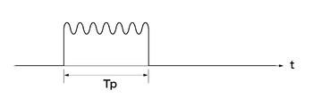
- the pulse light includes not only single pulse light but also a burst signal composed of a plurality of pulses (pulse width: Ts) as shown in FIGS. 11 and 14, for example.
- the pulse width Tp at this time is the burst length.
- a distance measuring apparatus 1 according to a fifth aspect of the present invention is the same as the distance measuring apparatus 1 according to any one of the second to fourth aspects. 5), as shown in (2) of FIG. 5, it is determined whether the Tr1 and the Tm are separated, the time difference between the first reference light r1 and the measurement received light mr is determined by the pulse width Tp of the pulsed light. Do by comparing to standards.
- the pulse light includes not only single pulse light but also a burst signal composed of a plurality of pulses (pulse width: Ts) as shown in FIGS. 11 and 14, for example.
- the pulse width Tp at this time is the burst length.
- a distance measuring apparatus 1 is the invention according to any one of the first to fifth aspects, as shown in FIG.
- the optical delay generator 50 is an optical fiber.
- the optical fiber when the optical fiber is used, the optical fiber can be small and the optical delay generator having a large delay time can be realized. Therefore, the entire distance measuring device can be miniaturized.
- the distance measuring apparatus 1 is the invention according to any one of the second aspect to the sixth aspect.
- the photoelectric conversion unit 140 has a resonance circuit unit 170 that converts a received pulsed light signal into a damped vibration waveform, and the time difference is determined based on zero crossing points t1, t2,. To decide.
- the position on the time axis of the zero-crossing point of the damped oscillation waveform has little change on the time axis of the optical signal even if the amplitude of the received optical signal fluctuates. Therefore, the influence of various disturbances is small. In addition, high accuracy can be obtained because the zero point that is less affected by fluctuations in offset voltage generated by electrical processing is used as a reference. In particular, since the first zero crossing point t1 after the start of vibration is more stable on the time axis than the other zero crossing points t2,..., Tn, the time difference is based on this zero crossing point t1. It is desirable to decide.
- the distance measuring method is, for example, as shown in FIG. 1, FIG. 4, FIG. 5, and FIG.
- a light source 10 that emits pulses in synchronization with the trigger signal Trg, a light separation unit 30 that branches light from the light source 10 into a first reference light r1, a second reference light r2, and a measurement transmission light mt;
- a first reference optical path R1 that allows the first reference light r1 to pass therethrough and does not cause an optical distance change; and an optical delay generator 50 that generates a temporal delay with respect to the first reference optical path R1.
- a reference optical path switching unit 60 having a function of passing one of the first reference optical path R1 and the second reference optical path R2, passing both, and blocking both.
- the constant light amount adjusting unit 90 (91 (see FIG. 2), 92), the output light of the first reference optical path R1, the output light of the second reference optical path R2, and the measurement received light mr received by the receiving unit 110r are combined.
- a distance measuring method using a distance measuring device 1 including a light combining unit 70 and a photoelectric conversion unit 140 that converts an optical signal combined by the light combining unit 70 into an electric signal is: (1) The reference light path switching unit 60 is controlled to pass through the first reference light path R1 and the second reference light path R2, and the measurement light amount adjusting unit 90 is controlled to block the measurement transmission light mt or the measurement reception light mr.
- Tr1 Measuring and storing the time difference (Tr1) between the trigger signal Trg and the first reference light r1 and the time difference (Tr2) between the trigger signal Trg and the second reference light r2 from the output of the photoelectric conversion unit 140 (S10); (2) The first reference optical path R1 and the second reference optical path R2 are blocked, and the measurement transmission light mt and the measurement reception light mr are passed, and the time difference (Tm) between the measurement reception light mr and the trigger signal Trg is measured.
- Second measurement for determining the measurement optical path difference (Tt) by obtaining Tm and further obtaining Td Tr2-Tr1 from the values of Tr2 and Tr1 obtained in (1) and calculating Td ⁇ Td ′.
- the measurement received light and the reference light can be separated on the time axis as in the long-distance measurement, so that the processing is simplified and high-accuracy measurement is possible.
- the measurement reception light and the reference light are not sufficiently separated on the time axis, such as near-field measurement, and high accuracy is not possible, the measurement reception light and the reference light can be separated by inserting a delay means.
- it is possible to cancel the passage time variation due to the temperature change of the delay means it is possible to measure with high accuracy.
- FIG. 1 is an overall configuration diagram of a distance measuring device according to a first embodiment of the present invention.
- Configuration with a measurement light intensity adjustment unit on the transmission side Configuration of transmitter / receiver using prism
- the figure which shows each part waveform of the measurement (far distance: case 1) by this invention The figure which shows each part waveform of the measurement (short distance: case 2) by this invention
- the figure which shows the measurement procedure of this invention Example of a resonant circuit for generating a damped vibration waveform Diagram showing input / output waveforms for generating damped vibration waves
- the figure explaining the optical pulse signal modulated with the chirp signal A diagram for explaining an amplitude-modulated light pulse Diagram explaining correlation detection of specific pattern Diagram explaining the principle of conventional measurement
- the light source unit 10 generates optical pulse light (measurement transmission light mt) at a constant timing based on the trigger signal Trg.
- the light source unit 10 includes a light emitting element 12 and a light emission drive circuit 11 that drives the light emitting element 12.
- the light-emitting element 12 is typically a semiconductor laser capable of irradiating a thin measurement beam 160 to a long-distance measurement object 160, but any LED that can measure the distance from the short-distance measurement object 160 is used.
- a non-coherent light source such as Here, a semiconductor laser, particularly a pulse laser diode will be described.
- the light emission drive circuit 11 drives a drive current to the light emitting element 12, and flows a current equal to or greater than a threshold only during a period during which light emission is desired. That is, a drive current is passed at a stroke at the moment when it is desired to emit light.
- the light emission drive circuit 11 generates a light emitting element drive pulse having a necessary pulse width based on the trigger signal. However, the drive pulse may be a single pulse, or a repetitive pulse having a predetermined cycle based on the trigger signal Trg. It may be.
- the light pulse generated by the light emitting element 12 is converted into a parallel light beam by the collimating lens 20.
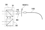
- the light pulse converted into a parallel light beam by the collimator lens 20 is split by the light separation unit 30 into the measurement transmission light mt, the first reference light r1, and the second reference light r2.
- the light separation unit 30 includes two beam splitters 31 and 32. That is, the parallel light beam from the collimating lens 20 is separated into two by the beam splitter 31, one light beam is used as the measurement transmission light mt, the other light beam is further divided into two by the beam splitter 32, and each of the first reference light beam r1.
- the measurement transmission light mt output from the beam splitter 31 is collected by the condenser lens 80 and input to the optical fiber 100 for connection to the transmission unit 110t.
- the measurement transmission light mt propagated in the optical fiber 100 is converted into a parallel light beam again by the collimator lens 111, the direction thereof is bent at a right angle by the light projection mirror 112, and a hole opened near the center of the objective lens 113. Irradiation toward the measurement object 160 through 113a.
- the light reflected by the measurement object 160 is collected by the objective lens 113 provided in the receiving unit 110r and input to the connection optical fiber 120.
- the light propagating through the optical fiber 120 is converted into a parallel light beam by the collimator lens 81.
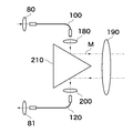
- FIG. 3 shows another embodiment of the transmission unit 110t / reception unit 110r. As shown in the figure, this embodiment is configured by inserting a prism 210 between the lens 180 and the lens 190 and between the lens 200 and the lens 190.
- a measurement light amount adjustment unit 90 (91, 92) is provided.
- the measurement light amount adjustment unit may be inserted on the transmission side or the reception side, but is preferably on the reception side. If the amount of light is changed on the transmission side, the amount of internal reflection noise due to surface reflections of optical components inside the device will change, making it difficult to obtain a stable distance measurement accuracy. This is because the amount of reflected noise is constant and stable ranging accuracy can be obtained. These give desired attenuation to the incident light, and are controlled by the measurement control unit 150.
- the amount of attenuation can be infinite, and if it is configured so that incident light can be completely blocked, it can also be used as a measuring light blocking means described later.
- the measurement light amount adjustment unit 90 (91, 92) is arranged at a position other than the position shown in FIG. 1 such as between the condenser lens 80 and the light separation unit 30 or between the collimator lens 81 and the light synthesis unit 70. May be.
- the first reference light r1 and the second reference light r2 separated by the beam splitter 32 are selected as reference light by the reference light path switching unit 60.
- the separated first reference light r1 and second reference light r2 are input to the first reference light path switch 61 and the second reference light path switch 62, respectively.
- the first reference optical path switching unit 61 and the second reference optical path switching unit 62 are controlled by the measurement control unit 150 and are configured to be able to execute either blocking or blocking incident light.
- the light that has passed through the first reference optical path switch 61 is input to the light combining unit 70 via the first reference optical path R1.
- the first reference optical path R1 is typically a simple space with a short optical path length. That is, the first reference optical path switching unit 61 and the light combining unit 70 are optically directly connected, and optical distance change hardly occurs.
- a short optical fiber that does not cause a practical change in distance can be used. For example, when the accuracy is 1 millimeter, the length of the optical fiber is about several tens of centimeters.
- the light that has passed through the second reference optical path switch 62 is input to the light combining unit 70 via the second reference optical path R2.
- An optical delay generator 50 is inserted in the second reference optical path R2.
- the optical delay generator 50 gives a difference in propagation time between the first reference optical path R1 and the second reference optical path R2, and is typically an optical fiber. More specifically, a graded index fiber.
- the lights respectively propagated through the first reference optical path R1 and the second reference optical path R2 are combined by the beam splitter 71 in the light combining unit 70, and the combined signal is adjusted in level by the reference light amount adjusting unit 93. Further, it is combined with the measurement received light mr by the beam splitter 72.
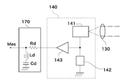
- the optical signal synthesized by the beam splitter 72 is condensed by the condenser lens 130 and is incident on the light receiving element 141 provided in the photoelectric conversion unit 140.
- the light receiving element 141 is typically an APD (avalanche photodiode), but other elements may be used as long as they sufficiently respond to the light pulse emitted from the light source unit 10 and have the necessary sensitivity.
- the detection output of the light receiving element 141 appears as an electrical signal at both ends of the load 142, is amplified by the preamplifier 143, and is output as the measurement output Mes.
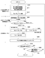
- this procedure includes (1) a calibration data acquisition routine, (2) a target (measuring object) approximate position detection routine, and (3) a distance measurement routine.
- the distance measurement routine is further divided into a first measurement and a second measurement according to the distance to the measurement object.
- step S10 a difference Td between the light passage times of the first reference optical path R1 and the second reference optical path R2 is obtained, and this value is stored.
- Step S10 includes steps S11 to S12.
- step S ⁇ b> 11 the first reference optical path switching unit 61 and the second reference optical path switching unit 62 are passed by the instruction of the measurement control unit 150, and the measured light amount adjustment unit 90 is shut off.
- step S12 the time difference Td between the first reference light r1 and the second reference light r2 is measured. In this way, the light from the light source unit 10 propagates through the first reference optical path R1 and the second reference optical path R2 and enters the photoelectric conversion unit 140, but does not propagate the measurement transmission light mt. .
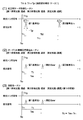
- This state is shown in (1) of FIG. 4 and (1) of FIG. 4 and 5, Tr1 and Tr2 are measured based on the timing T0 of the trigger signal Trg.
- the measurement is not limited to this, and a constant time interval is maintained with the measurement transmission light mt. Just do it.
- processing based on the timing T0 of the trigger signal Trg can be processed as an electric signal, and there are few unstable elements, and highly accurate measurement can be performed. The following description is based on T0.
- FIG. 4 (1) and FIG. 5 (1) show output waveforms of the photoelectric conversion unit 140 of the first reference light r1 and the second reference light r2.
- the first reference light r1 and the second reference light r2 are received by the light receiving element 141, they are delayed by Tr1 and Tr2 from the reference time T0, respectively.
- Each pulse width is Tp (in the case where the output waveform of the light source unit is a burst signal composed of a set of a plurality of pulses, as will be described later).
- the first reference light r1 and the second reference light are received so that the first reference light r1 and the second reference light r2 are received at a fixed timing with reference to the time when the trigger signal Trg is input.
- Tr2 fluctuates due to a temperature change of the optical fiber as the optical delay generation unit 50 inserted in the second reference optical path R2. This fluctuation amount is assumed to be ⁇ Tr2.
- ⁇ Tr1 since the first reference optical path R1 does not include a large delay element, ⁇ Tr1 can be almost ignored.
- ⁇ Tr2 causes a measurement error.
- the present invention is characterized in that this error can be offset. This point will be described in detail later.
- the measurement light is transmitted through the measurement light path M through the measurement light amount adjustment unit 90, the first reference optical path R1 and the second reference optical path R2 are blocked, and the measurement reception light mr is observed by the photoelectric conversion unit 140.
- the reception timing Tm is measured (step S20).
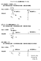
- Tm ⁇ Tr1 + Tp (Case 2) or Tm ⁇ Tr1 + Tp (Case 1) it is determined whether Tm ⁇ Tr1 + Tp (Case 2) or Tm ⁇ Tr1 + Tp (Case 1) (Step S30).
- Case 2 corresponds to a case where the distance between the measurement object 160 and the distance measuring device 1 is short, and is a case where the pulses of the measurement reception light mr and the first reference light r1 overlap in time.
- the waveform in such a case is shown in (2) of FIG. Case 1 corresponds to a case where the distance between the measurement object 160 and the distance measuring device 1 is long, and the pulses of the measurement reception light mr and the first reference light r1 do not overlap in time.
- the waveform in such a case is shown in FIG.
- Tt Tm ⁇ Tr1 (2)
- L cTt / 2 (3)
- c the speed of light.
- Case 2 corresponds to a case where measurement based on the first reference light r1 is impossible.
- the process of step S50 in FIG. 6 is executed. That is, the following calculation is performed using the time difference Td ′ between Tr2 and Tm and Td stored in the memory (steps S51 and S52).
- Td Tr2-Tr1 (4)
- Td ' Tr2-Tm (5)
- Tt Td ⁇ Td ′ (6)
- the distance L to the measurement object 160 is obtained using the equation (3) (step S ⁇ b> 60).
- measurement is performed with reference to the second reference light r2 having different transit times of the first reference light r1, thereby separating the overlapping of the pulses of the measurement reception light mr and the first reference light r1. I can do it.
- Tr1 is affected by fluctuations, as described above, Tr1 is set to have a short delay time, so that the influence of temperature change is small. Therefore, highly accurate measurement can be performed with almost no influence of temperature or the like.
- step S70 it is further determined whether or not the measurement environment has been changed in the next measurement (step S80).
- “change in measurement environment” refers to a case where the calibration data measured in step S10 changes due to a change in temperature, a change in the installation location of the distance measurement device, or the like. If such a change does not occur (“NO” in step S80), the process returns to step S20 and the measurement is repeated.
- the measurement environment fluctuates (“YES” in step S80)
- the process returns to step S10, Td as calibration data is measured again, and the stored measurement value is rewritten.
- step S10 Since it is such a structure, it is not necessary to implement step S10 for every measurement in every measurement. Therefore, quick measurement is possible.
- step S70 the flow of FIG. 6 is finished.
- step S80 can be omitted when the calibration data acquisition step is performed every measurement or when the calibration data acquisition process is omitted at every measurement.
- the determinations in step S70 and step S80 may be performed automatically according to a predetermined procedure, or may be performed manually every measurement.
- the level between the first reference light r1 and the second reference light r2 is that the propagation path is in the distance measuring device, so that an appropriate level adjusting means is provided in the first reference light path R1 or the second reference light path R2. There is no need to adjust according to the measurement environment.
- the level of the measurement reception light mr varies depending on the measurement environment such as the measurement distance L and the reflection condition of the measurement object 160. As shown in FIG. 1, in the present embodiment, a measurement light amount adjustment unit 92 is provided on the receiving side in order to absorb this variation.
- the actual measurement light amount adjustment unit 91 may be provided on the transmission side, or may be provided on both the transmission side and the reception side.
- the measurement light amount adjusting unit 90 for example, a mechanism that mechanically adjusts the ND filter or an electro-optical effect such as a liquid crystal transmission plate can be used. Note that, as in step S11 of FIG. 6, it is necessary to completely block the transmitted light because it is necessary to completely block the measurement optical path M.
- These controls are performed by the measurement control unit 150 based on the detection result of the level detection means (not shown). In addition to the above automatic control, there is a form of manual control.
- Td is the difference between the time required for the first reference light r1 and the second reference light r2 to pass through the respective optical paths, and the delay time setting value Tq of the substantially optical delay generator 50. However, it is slightly shifted due to the delay time of other parts of the distance measuring device. Even in such a case, in order to prevent the first reference light r1 and the second reference light r2 from overlapping in time and to determine Td with high accuracy, Tq is set to the pulse width Tp of the measured transmission light pulse. (In the case where one measurement transmission light is a burst light composed of n single pulses having a pulse width Ts as shown in FIG. 11 described later, Tp> nTs) is preferable.
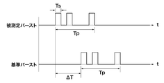
- Tr1, Tr2, and Tm For the measurement of Tr1, Tr2, and Tm, a known technique for measuring the time difference ⁇ T between two pulses can be used. For example, in order to measure the time difference between the start signal M1 (pulse signal) and the stop signal M2 (pulse signal), two reference signals S1 and S2 having a phase difference of ⁇ / 2 are generated from a reference frequency generator and started.
- the phase difference ⁇ is detected, and the detected phase difference ⁇ and
- a method of calculating ⁇ T based on the period of the reference signals S1 and S2 for example, JP 2006-133214 A: pulse time difference method.
- FIG. 7 shows a configuration when the damped vibration wave zero-crossing method is applied.
- a resonance circuit 170 is connected to the output end of the photoelectric conversion unit 140.
- the resonance circuit 170 is typically a series or parallel circuit of a resistor Rd, an inductance Ld, and a capacitor Cd.
- Rd includes the output resistance of the preamplifier 143.
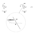
- FIG. 8 shows output waveforms of the photoelectric conversion unit 140 and the resonance circuit 170.
- a damped oscillation waveform is obtained for the single pulse shown in FIG.
- a broken line indicates a case where the peak value fluctuates (increases).
- the zero crossing points t1 to Tn do not fluctuate even if the peak value fluctuates. Therefore, if the time difference between the reference time point and the zero crossing point t1 that is most stable in terms of waveform is measured, a highly accurate measurement can be performed.
- FIG. 10 shows a case where two damped vibration waves are present close in time. For example, the time difference between the first reference light r1 and the measurement reception light mr is obtained. As described above, it is possible to measure with high accuracy by detecting the zero crossing point of the damped vibration wave. However, if there is an interference wave in the vicinity of this zero crossing point, a measurement error of the timing of the zero crossing point occurs. Accordingly, when the decay of the decay waveform of the first reference light r1 continues until near the zero crossing point of the measurement reception light mr as shown in FIG. 10, the measurement reception is performed so that the afterglow component of the first reference light r1 is sufficiently attenuated.
- the first period of the measurement received light mr is approximated by a sine wave having an amplitude level S (voltage display) and a frequency fs.
- the frequency fs is the resonance frequency of the resonance circuit 170.
- the measurement distance errors ⁇ Ls and (N / S) due to the interference wave are as follows. There is a relationship.
- the above is the result when the first reference light r1 is used, but similar interference occurs when the second reference light r2 is used. Since the distance measurement range when using the first reference light r1 is set to 50 m or more, the measurement light is closest to the second reference light r2 in time when the measurement object 160 exists at a distance of 50 m. is there. Therefore, in the case where measurement is performed using the second reference light r2 (case 1 in FIG. 4), the necessary optical distance is required in order to make the influence of the interference wave negligible (N / S ⁇ 1/800). Needs to be set to 100m with 50m added. Since the optical distance 100 m is a value obtained by converting the round trip of light as a measurement distance, the distance that light actually travels is 200 m.
- the optical delay generator 50 when the optical delay generator 50 is realized by an optical fiber, the physical length is 130 m in consideration of the refractive index (1.5) of the optical fiber.
- the accuracy is improved, but a large delay generation unit is required, and the variation of the delay time due to temperature or the like becomes large. Even in such a case, if the present invention is applied, the passage time fluctuation is canceled out, so that highly accurate measurement can be maintained.
- the pulse width Tp ′ of the optical pulse signal converted into the electric signal is wider than the pulse width Tp of the measurement transmission light mt. Accordingly, among the descriptions related to the pulse width Tp described so far, the duration of the damped oscillation Tp ′ is used for the received light pulse width instead of Tp in the case of a single pulse.
- Tp ′ is determined by the attenuation constant ⁇ and the pulse width Tp of the measurement transmission light mt.
- the transmission measurement light mt is a single pulse.
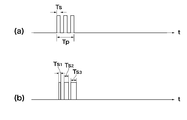
- the single pulse there are embodiments as shown in FIGS.
- FIG. 11A shows a case where a light pulse (pulse width: Tp) is a burst-like pulse in which a plurality of single pulses (pulse width: Ts) are continuously continued.
- FIG. 11 (b) shows a case where each single pulse continues with different pulse widths Ts1, Ts2, and Tsn in the case of the burst-like pulse of FIG. 11 (a).
- FIG. 12 shows an optical pulse modulated with a chirp signal.
- the chirp signal is a signal whose frequency continuously changes over time.
- FIG. 13 shows an optical pulse whose amplitude is modulated.
- FIG. 14 shows a case where one light pulse is constituted by a code having a specific pattern.
- the detection times of the received measurement light mr and the reference lights r1 and r2 can be accurately measured.
- DESCRIPTION OF SYMBOLS 1 Distance measuring device 10 Light source part 11 Light emission drive circuit 12 Light emitting element 20 Collimator lens 30 Light separation part 31 Beam splitter 32 Beam splitter 50 Optical delay generation unit 60 Reference optical path switching unit 61 First reference optical path switching unit 62 Second reference optical path switching unit 70 Light combining unit 71 Beam splitter 72 Beam splitter 80 Condensing lens 81 Collimating lens 90 Measurement light quantity Adjustment unit 91 Measurement light quantity adjustment unit (transmission side) 92 Measurement light intensity adjustment unit (reception side) 93 Reference light amount adjusting unit 100 Optical fiber 104 Photodetector 110r Receiving unit 110t Transmitting unit 111 Collimating lens 112 Projecting mirror 113 Objective lens 113a Hole (objective lens) 120 optical fiber 130 condensing lens 140 photoelectric conversion unit 141 light receiving element 143 preamplifier 150 measurement control unit 160 measurement object 170 resonance circuit 180 lens 190 lens 200 lens 210 prism Cont control signal M measurement optical path Mes measurement output mr
Landscapes
- Physics & Mathematics (AREA)
- Engineering & Computer Science (AREA)
- Electromagnetism (AREA)
- Computer Networks & Wireless Communication (AREA)
- General Physics & Mathematics (AREA)
- Radar, Positioning & Navigation (AREA)
- Remote Sensing (AREA)
- Optical Radar Systems And Details Thereof (AREA)
- Measurement Of Optical Distance (AREA)
Priority Applications (3)
| Application Number | Priority Date | Filing Date | Title |
|---|---|---|---|
| EP09834795.8A EP2375265B1 (en) | 2008-12-25 | 2009-12-18 | Distance measurement device and distance measurement method |
| CN2009801515252A CN102265178B (zh) | 2008-12-25 | 2009-12-18 | 距离测定装置及距离测定方法 |
| US13/141,541 US8610880B2 (en) | 2008-12-25 | 2009-12-18 | Distance measuring apparatus and distance measuring method |
Applications Claiming Priority (2)
| Application Number | Priority Date | Filing Date | Title |
|---|---|---|---|
| JP2008-330162 | 2008-12-25 | ||
| JP2008330162A JP5683782B2 (ja) | 2008-12-25 | 2008-12-25 | 距離測定装置及び距離測定方法 |
Publications (1)
| Publication Number | Publication Date |
|---|---|
| WO2010073994A1 true WO2010073994A1 (ja) | 2010-07-01 |
Family
ID=42287604
Family Applications (1)
| Application Number | Title | Priority Date | Filing Date |
|---|---|---|---|
| PCT/JP2009/071145 Ceased WO2010073994A1 (ja) | 2008-12-25 | 2009-12-18 | 距離測定装置及び距離測定方法 |
Country Status (5)
| Country | Link |
|---|---|
| US (1) | US8610880B2 (enExample) |
| EP (1) | EP2375265B1 (enExample) |
| JP (1) | JP5683782B2 (enExample) |
| CN (1) | CN102265178B (enExample) |
| WO (1) | WO2010073994A1 (enExample) |
Cited By (1)
| Publication number | Priority date | Publication date | Assignee | Title |
|---|---|---|---|---|
| CN117269949A (zh) * | 2023-11-22 | 2023-12-22 | 深圳市中图仪器股份有限公司 | 用于扩展调频连续波测距范围的方法及装置 |
Families Citing this family (24)
| Publication number | Priority date | Publication date | Assignee | Title |
|---|---|---|---|---|
| US10588107B2 (en) * | 2012-10-26 | 2020-03-10 | Telefonaktiebolaget Lm Ericsson (Publ) | Methods of positioning in a system comprising measuring nodes with multiple receiving points |
| CN105164550B (zh) * | 2014-02-28 | 2018-10-12 | 松下知识产权经营株式会社 | 测距装置以及测距方法 |
| CN104849718B (zh) * | 2014-04-25 | 2017-02-15 | 常州市新瑞得仪器有限公司 | 激光测距仪 |
| JP6700575B2 (ja) * | 2015-09-25 | 2020-05-27 | 株式会社リコー | 回路装置、光検出器、物体検出装置、センシング装置、移動体装置、光検出方法、及び物体検出方法 |
| JP2017072466A (ja) * | 2015-10-07 | 2017-04-13 | 株式会社トプコン | 光波距離測定装置 |
| TWI557393B (zh) * | 2015-10-08 | 2016-11-11 | 微星科技股份有限公司 | 雷射測距校正方法與應用此方法的裝置 |
| WO2017119118A1 (ja) * | 2016-01-08 | 2017-07-13 | オリンパス株式会社 | 標本形状測定方法及び標本形状測定装置 |
| US11086014B2 (en) | 2016-02-02 | 2021-08-10 | Sony Corporation | Ranging device, ranging method, signal processing device, and light projecting device |
| JP6693783B2 (ja) * | 2016-03-24 | 2020-05-13 | 株式会社トプコン | 距離測定装置およびその校正方法 |
| JP6774192B2 (ja) * | 2016-03-24 | 2020-10-21 | 株式会社トプコン | 距離測定装置および距離測定方法 |
| US10436572B2 (en) * | 2016-03-30 | 2019-10-08 | Hitachi, Ltd. | Three-dimensional shape measuring apparatus, three-dimensional shape measuring probe |
| US10564042B1 (en) * | 2016-04-18 | 2020-02-18 | The Government Of The United States Of America, As Represented By The Secretary Of The Navy | Advantages of spatial demodulation in interferometric optical sensing applications |
| CN106289073B (zh) * | 2016-09-29 | 2018-12-14 | 清华大学深圳研究生院 | 飞秒激光测距装置和方法 |
| CN107884762A (zh) * | 2016-09-30 | 2018-04-06 | 比亚迪股份有限公司 | 激光雷达及车辆 |
| DE112017007344T5 (de) | 2017-03-31 | 2019-12-12 | Sony Corporation | Abstandsmessvorrichtung und fahrzeug |
| WO2019031510A1 (ja) * | 2017-08-08 | 2019-02-14 | 国立大学法人静岡大学 | 距離画像測定装置及び距離画像測定方法 |
| JP6838532B2 (ja) * | 2017-09-08 | 2021-03-03 | オムロン株式会社 | センサ装置および測定方法 |
| DE102018125253B3 (de) * | 2018-10-12 | 2019-12-24 | Pepperl+Fuchs Gmbh | Optischer Sensor nach dem Laufzeitprinzip zum Nachweis von Objekten in einem Überwachungsbereich |
| JP7240947B2 (ja) * | 2019-05-09 | 2023-03-16 | 株式会社アドバンテスト | 光学試験用装置 |
| CN110471075B (zh) * | 2019-08-23 | 2021-07-30 | 森思泰克河北科技有限公司 | 雷达测距方法、装置及终端设备 |
| CN113820689B (zh) * | 2020-06-18 | 2024-05-17 | 华为技术有限公司 | 接收器、激光测距设备及点云图像生成方法 |
| JP2023149250A (ja) * | 2022-03-30 | 2023-10-13 | 株式会社トプコン | 測量機 |
| CN116482662B (zh) * | 2023-06-25 | 2023-08-22 | 成都量芯集成科技有限公司 | 一种光学测距仪自校准系统及其自校准方法 |
| CN120526859B (zh) * | 2025-07-23 | 2025-09-30 | 杭州柏恒科技有限公司 | 一种多通道荧光相关光谱的多聚体检测数据处理方法 |
Citations (9)
| Publication number | Priority date | Publication date | Assignee | Title |
|---|---|---|---|---|
| JPS57147800A (en) | 1981-02-03 | 1982-09-11 | Mitetsuku Moderune Ind Tech Gm | Remote measuring method and apparatus based on measuring light pulse propagation time |
| JPH05232229A (ja) | 1992-02-21 | 1993-09-07 | Topcon Corp | パルス信号検出装置及び光波距離計 |
| JPH05232231A (ja) | 1992-02-21 | 1993-09-07 | Topcon Corp | 光学的遅延手段を有する光波距離計 |
| JPH08226969A (ja) * | 1995-02-21 | 1996-09-03 | Topcon Corp | 位相差測定装置及び光波距離計における遮光板制御装置 |
| JP2003185747A (ja) | 2001-12-18 | 2003-07-03 | Topcon Corp | パルス方式の光波距離計 |
| JP2004257961A (ja) * | 2003-02-27 | 2004-09-16 | Komatsu Engineering Corp | 光波位相差測定装置及び光波位相差測定方法 |
| JP2006133214A (ja) | 2004-10-04 | 2006-05-25 | Topcon Corp | 時間差測定装置および測定方法並びに測距装置および測距方法 |
| JP2007093514A (ja) * | 2005-09-30 | 2007-04-12 | Topcon Corp | 距離測定装置 |
| JP2007127541A (ja) * | 2005-11-04 | 2007-05-24 | Sokkia Co Ltd | 光波距離計 |
Family Cites Families (17)
| Publication number | Priority date | Publication date | Assignee | Title |
|---|---|---|---|---|
| US3729249A (en) * | 1968-07-12 | 1973-04-24 | Ibm | Method and apparatus for large object interference pattern recording |
| CH641279A5 (de) * | 1979-07-13 | 1984-02-15 | Kern & Co Ag | Verfahren zur messung der entfernung zwischen einem objekt und einem bezugspunkt, sowie vorrichtung zu dessen durchfuehrung. |
| DE3219423C2 (de) * | 1981-06-09 | 1986-04-30 | MTC, Meßtechnik und Optoelektronik AG, Neuenburg/Neuchâtel | Entfernungsmeßverfahren und Vorrichtung zu seiner Durchführung |
| DE3540157A1 (de) * | 1985-11-13 | 1987-05-21 | Messerschmitt Boelkow Blohm | Verfahren und vorrichtung zur entfernungsmessung |
| JP2896782B2 (ja) * | 1988-12-30 | 1999-05-31 | 株式会社トプコン | パルス方式の光波距離計 |
| JP3120202B2 (ja) * | 1993-11-18 | 2000-12-25 | 株式会社トプコン | パルス方式の光波距離計 |
| CN1110398A (zh) * | 1993-12-27 | 1995-10-18 | 现代电子产业株式会社 | 光学测距装置及其方法 |
| US6429941B1 (en) * | 1998-07-14 | 2002-08-06 | Minolta Co., Ltd. | Distance measuring equipment and method |
| JP2001074827A (ja) * | 1999-09-07 | 2001-03-23 | Minolta Co Ltd | 測距装置 |
| EP1251363B1 (de) * | 2001-04-20 | 2005-04-27 | Krohne Messtechnik Gmbh & Co. Kg | Verarbeitungsverfahren für ein Frequenzsignal |
| JP3956890B2 (ja) * | 2002-06-10 | 2007-08-08 | 松下電工株式会社 | 距離計測装置及び距離計測方法 |
| US6829042B1 (en) * | 2002-06-10 | 2004-12-07 | Matsushita Electric Works, Ltd. | Distance measuring apparatus and method using a pulsed electromagnetic wave |
| JP2004136719A (ja) * | 2002-10-15 | 2004-05-13 | Koito Mfg Co Ltd | 点灯回路 |
| WO2006014406A2 (en) * | 2004-06-30 | 2006-02-09 | Zygo Corporation | Interferometric optical assemblies and systems including interferometric optical assemblies |
| JP2007029603A (ja) * | 2005-07-29 | 2007-02-08 | Fujinon Corp | 光診断治療装置 |
| JP4898176B2 (ja) * | 2005-09-26 | 2012-03-14 | 株式会社トプコン | 測量装置及び測量方法 |
| ATE516739T1 (de) * | 2005-12-06 | 2011-08-15 | Zeiss Carl Meditec Ag | Interferometrische probenmessung |
-
2008
- 2008-12-25 JP JP2008330162A patent/JP5683782B2/ja active Active
-
2009
- 2009-12-18 CN CN2009801515252A patent/CN102265178B/zh not_active Expired - Fee Related
- 2009-12-18 US US13/141,541 patent/US8610880B2/en active Active
- 2009-12-18 EP EP09834795.8A patent/EP2375265B1/en not_active Not-in-force
- 2009-12-18 WO PCT/JP2009/071145 patent/WO2010073994A1/ja not_active Ceased
Patent Citations (9)
| Publication number | Priority date | Publication date | Assignee | Title |
|---|---|---|---|---|
| JPS57147800A (en) | 1981-02-03 | 1982-09-11 | Mitetsuku Moderune Ind Tech Gm | Remote measuring method and apparatus based on measuring light pulse propagation time |
| JPH05232229A (ja) | 1992-02-21 | 1993-09-07 | Topcon Corp | パルス信号検出装置及び光波距離計 |
| JPH05232231A (ja) | 1992-02-21 | 1993-09-07 | Topcon Corp | 光学的遅延手段を有する光波距離計 |
| JPH08226969A (ja) * | 1995-02-21 | 1996-09-03 | Topcon Corp | 位相差測定装置及び光波距離計における遮光板制御装置 |
| JP2003185747A (ja) | 2001-12-18 | 2003-07-03 | Topcon Corp | パルス方式の光波距離計 |
| JP2004257961A (ja) * | 2003-02-27 | 2004-09-16 | Komatsu Engineering Corp | 光波位相差測定装置及び光波位相差測定方法 |
| JP2006133214A (ja) | 2004-10-04 | 2006-05-25 | Topcon Corp | 時間差測定装置および測定方法並びに測距装置および測距方法 |
| JP2007093514A (ja) * | 2005-09-30 | 2007-04-12 | Topcon Corp | 距離測定装置 |
| JP2007127541A (ja) * | 2005-11-04 | 2007-05-24 | Sokkia Co Ltd | 光波距離計 |
Non-Patent Citations (3)
| Title |
|---|
| GORACHAUD GHOSH: "TemperatureDispersion of Refractive Indexes in some Silicate Fiber Glasses", IEEEPHOTONICS TECHNOGY LETTERS, vol. 6, no. 3, pages 431 |
| I.H.MALITSON: "Interspecimen Comparisonof the Refractive Index of Fused Silica", JOURNAL OF THE OPTICAL SOCIETYOF AMERICA, vol. 55, no. 10, October 1965 (1965-10-01), pages 1205 |
| See also references of EP2375265A4 |
Cited By (2)
| Publication number | Priority date | Publication date | Assignee | Title |
|---|---|---|---|---|
| CN117269949A (zh) * | 2023-11-22 | 2023-12-22 | 深圳市中图仪器股份有限公司 | 用于扩展调频连续波测距范围的方法及装置 |
| CN117269949B (zh) * | 2023-11-22 | 2024-02-13 | 深圳市中图仪器股份有限公司 | 用于扩展调频连续波测距范围的方法及装置 |
Also Published As
| Publication number | Publication date |
|---|---|
| CN102265178B (zh) | 2013-05-29 |
| CN102265178A (zh) | 2011-11-30 |
| US20110310377A1 (en) | 2011-12-22 |
| EP2375265A1 (en) | 2011-10-12 |
| US8610880B2 (en) | 2013-12-17 |
| EP2375265B1 (en) | 2013-09-18 |
| JP5683782B2 (ja) | 2015-03-11 |
| JP2010151618A (ja) | 2010-07-08 |
| EP2375265A4 (en) | 2012-08-08 |
Similar Documents
| Publication | Publication Date | Title |
|---|---|---|
| JP5683782B2 (ja) | 距離測定装置及び距離測定方法 | |
| JP2010151618A5 (enExample) | ||
| JP3839851B2 (ja) | 電子距離測定器具 | |
| CN100419456C (zh) | 光波距离计 | |
| JP6410258B2 (ja) | 光波距離計 | |
| US10921449B2 (en) | Dynamic expansion of a distance measuring device having a variable optical attenuation element in the transmitting channel | |
| JP2896782B2 (ja) | パルス方式の光波距離計 | |
| JP2006521536A5 (enExample) | ||
| EP1102034A2 (en) | Optical rangefinder | |
| WO2007020780A1 (ja) | 測量装置 | |
| KR101440085B1 (ko) | 레이저 거리 측정기 및 그 동작 방법 | |
| US10371803B2 (en) | Distance measuring device and method for calibrating the same | |
| JP6514920B2 (ja) | 光波距離計 | |
| US20240004044A1 (en) | Apparatus and method for measuring distant to and/or velocity of physical object | |
| KR101260280B1 (ko) | 3차원 광 스캔 장치 및 방법 | |
| JP5949341B2 (ja) | 距離測定装置 | |
| US20170276772A1 (en) | Distance measuring device and distance measuring method | |
| JP6609360B2 (ja) | 光波距離計 | |
| RU2408842C1 (ru) | Способ измерения расстояния и устройство для его осуществления (варианты) | |
| JPH04339289A (ja) | レーザ測距装置 | |
| RU2720268C1 (ru) | Лазерный дальномер | |
| JPH06186333A (ja) | レーザレーダ | |
| CN108761478A (zh) | 针对动态目标的绝对距离测量 | |
| JP2008008836A (ja) | 距離測定装置 | |
| KR101101739B1 (ko) | 거리 측정 장치 및 방법 |
Legal Events
| Date | Code | Title | Description |
|---|---|---|---|
| WWE | Wipo information: entry into national phase |
Ref document number: 200980151525.2 Country of ref document: CN |
|
| 121 | Ep: the epo has been informed by wipo that ep was designated in this application |
Ref document number: 09834795 Country of ref document: EP Kind code of ref document: A1 |
|
| NENP | Non-entry into the national phase |
Ref country code: DE |
|
| WWE | Wipo information: entry into national phase |
Ref document number: 2009834795 Country of ref document: EP |
|
| WWE | Wipo information: entry into national phase |
Ref document number: 13141541 Country of ref document: US |