WO2010073994A1 - 距離測定装置及び距離測定方法 - Google Patents
距離測定装置及び距離測定方法 Download PDFInfo
- Publication number
- WO2010073994A1 WO2010073994A1 PCT/JP2009/071145 JP2009071145W WO2010073994A1 WO 2010073994 A1 WO2010073994 A1 WO 2010073994A1 JP 2009071145 W JP2009071145 W JP 2009071145W WO 2010073994 A1 WO2010073994 A1 WO 2010073994A1
- Authority
- WO
- WIPO (PCT)
- Prior art keywords
- light
- measurement
- optical path
- unit
- reference light
- Prior art date
Links
Images


Classifications
-
- G—PHYSICS
- G01—MEASURING; TESTING
- G01S—RADIO DIRECTION-FINDING; RADIO NAVIGATION; DETERMINING DISTANCE OR VELOCITY BY USE OF RADIO WAVES; LOCATING OR PRESENCE-DETECTING BY USE OF THE REFLECTION OR RERADIATION OF RADIO WAVES; ANALOGOUS ARRANGEMENTS USING OTHER WAVES
- G01S17/00—Systems using the reflection or reradiation of electromagnetic waves other than radio waves, e.g. lidar systems
- G01S17/02—Systems using the reflection of electromagnetic waves other than radio waves
- G01S17/06—Systems determining position data of a target
- G01S17/08—Systems determining position data of a target for measuring distance only
- G01S17/32—Systems determining position data of a target for measuring distance only using transmission of continuous waves, whether amplitude-, frequency-, or phase-modulated, or unmodulated
- G01S17/34—Systems determining position data of a target for measuring distance only using transmission of continuous waves, whether amplitude-, frequency-, or phase-modulated, or unmodulated using transmission of continuous, frequency-modulated waves while heterodyning the received signal, or a signal derived therefrom, with a locally-generated signal related to the contemporaneously transmitted signal
-
- G—PHYSICS
- G01—MEASURING; TESTING
- G01S—RADIO DIRECTION-FINDING; RADIO NAVIGATION; DETERMINING DISTANCE OR VELOCITY BY USE OF RADIO WAVES; LOCATING OR PRESENCE-DETECTING BY USE OF THE REFLECTION OR RERADIATION OF RADIO WAVES; ANALOGOUS ARRANGEMENTS USING OTHER WAVES
- G01S17/00—Systems using the reflection or reradiation of electromagnetic waves other than radio waves, e.g. lidar systems
- G01S17/02—Systems using the reflection of electromagnetic waves other than radio waves
- G01S17/06—Systems determining position data of a target
- G01S17/08—Systems determining position data of a target for measuring distance only
- G01S17/10—Systems determining position data of a target for measuring distance only using transmission of interrupted, pulse-modulated waves
-
- G—PHYSICS
- G01—MEASURING; TESTING
- G01S—RADIO DIRECTION-FINDING; RADIO NAVIGATION; DETERMINING DISTANCE OR VELOCITY BY USE OF RADIO WAVES; LOCATING OR PRESENCE-DETECTING BY USE OF THE REFLECTION OR RERADIATION OF RADIO WAVES; ANALOGOUS ARRANGEMENTS USING OTHER WAVES
- G01S7/00—Details of systems according to groups G01S13/00, G01S15/00, G01S17/00
- G01S7/48—Details of systems according to groups G01S13/00, G01S15/00, G01S17/00 of systems according to group G01S17/00
- G01S7/497—Means for monitoring or calibrating
Definitions
- the present invention relates to a distance measuring apparatus and method for measuring a distance from a measurement object by irradiating the measurement object with a light pulse and measuring a time until the reflected light returns.
- the present invention relates to a distance measuring apparatus and method that can perform high-precision measurement in a distance measuring apparatus that employs a measurement method that includes a delay element in a reference optical path, by canceling the influence of temperature variation of the delay time of the delay element.
- pulse light is irradiated toward a measurement object, the pulse light reflected from the measurement object is detected by a distance measuring device, and the distance to the measurement object is measured from the round-trip propagation time of the pulse light.
- a distance measuring device Conventionally, pulse light is irradiated toward a measurement object, the pulse light reflected from the measurement object is detected by a distance measuring device, and the distance to the measurement object is measured from the round-trip propagation time of the pulse light.
- the distance measuring device 100 in order to perform measurement with as high accuracy as possible, a method is adopted in which the propagation time is determined in the light processing stage so as not to be affected by electrical fluctuations in the distance measuring device.
- the distance measuring device 100 is provided with a pulse light source 101, a reference optical path Rc branched from the pulse light source 101, and a photodetector 104, and an object to be measured based on the arrival time of the optical pulse in the reference optical path Rc.
- This is a system in which a difference in propagation time from the measurement optical path Mc up to 160 is detected by the photodetector 104 and the distance L is measured therefrom.
- the reference optical path Rc and the measurement optical path Mc are mechanically switched by the optical path switches 103a and 103b, and the propagation time of the pulsed light passing through each of the optical paths Rc and Mc is measured independently at different timings. The propagation time difference is calculated from the measurement result.
- this method is difficult to operate at high speed, and is a major factor that limits the reduction in measurement time.
- the reference light rc and the measurement light mc are synthesized without switching the light passing through the reference optical path Rc (reference light rc) and the light passing through the measurement optical path Mc (measurement light mc).
- a method of detecting with one photodetector is conceivable.
- the reference light rc and the measurement light mc overlap on the time axis, and the reference light rc. It is difficult to accurately detect the time difference between the measurement light mc and the measurement light mc (see case 1 in FIG. 15B).
- an optical delay generator whose delay time is accurately known in advance is inserted into the reference optical path Rc or the measurement optical path Mc, the measurement light mc and the reference light rc are separated on the time axis, and the time difference is measured. Thereafter, there is a method of correcting the time difference measured by the delay time value of the optical delay generator (see case 2 in FIG. 15B, for example, Patent Document 1).
- the pulse width of the pulse light source 101 is often about 10 nsec.
- a delay element when an optical fiber having a refractive index of 1.5 is used
- the minimum length is 2 meters.
- the delay time is set in consideration of a margin, it is desirable that the delay time be several times the pulse width or more. If it is attempted to obtain 100 ns, which is one digit or more, as the delay time, the length becomes about 20 meters when an optical fiber is used as the delay element.
- the noise level be about ⁇ 58 dB (1/800) or less. A long one of 200 meters or more in terms of distance is required.
- an optical fiber is suitable because it can be bent freely and a large delay time can be obtained with a small shape.
- the optical fiber has a characteristic that its propagation delay time changes with temperature.
- the temperature coefficient of the refractive index of the quartz fiber is about 10 ppm / ° C. (for example, Non-Patent Document 1, Non-Patent Document 2), and the fiber length is 130 meters that can obtain a delay time equivalent to the above 200 meters.
- the temperature change amount is 50 ° C.
- the measurement distance error due to the change in the delay time is about 10 cm. This error is unacceptable as an error of a precision distance measuring device aiming at a measurement accuracy of about 1 mm.
- JP 57-147800 A Japanese Patent Laid-Open No. 5-232231
- An object of the present invention is to realize a distance measuring apparatus and method capable of solving the above-described problems, canceling the influence of fluctuations in a delay circuit inside the distance measuring apparatus, and performing high-precision and high-speed measurement.
- a distance measuring apparatus 1 includes, for example, a light source unit 10 that emits light in a pulse manner in synchronization with a trigger signal Trg, as shown in FIG. 10 is split into the first reference light r1, the second reference light r2, and the measurement transmission light mt, and the first reference light path that allows the first reference light r1 to pass therethrough without causing an optical distance change.
- R1 and an optical delay generator 50 that generates a large time delay with respect to the first reference optical path R1, and includes a second reference optical path R2, a first reference optical path R1, and a first reference optical path R1 that pass the second reference light r2.
- a reference optical path switching unit 60 having a function of passing either one of the two reference optical paths R2, passing both, and blocking both, and a transmission unit that irradiates the measurement transmission light mt to the measurement object 160 110t and irradiated measurement transmission light m
- a reception unit 110r that receives the measurement reception light mr reflected by the measurement object 160, a measurement light amount adjustment unit 90 (91 (see FIG.
- the light combining unit 70 that combines the output light of the first reference optical path R1, the output light of the second reference optical path R2, and the measurement received light mr received by the receiving unit 110r, and the optical signal combined by the light combining unit 70 as an electrical signal
- a measurement control unit 150 A measurement control unit 150.
- pulsed light emission in synchronization with the trigger signal Trg means that the light emission timing is determined based on the timing of the trigger signal Trg, in other words, the timing of the trigger signal Trg and the timing of light emission. There should be a certain relationship in the time between.
- Pulse emission means that the light includes both a single pulse and a repetitive pulse and is not continuous light.
- Luminescence is the generation of light including visible and invisible light.
- the “light source” includes all of coherent light such as a laser beam and non-coherent light emitted from an LED or the like.
- the “first reference optical path that does not cause an optical distance change” means that a change in the passage time that occurs in the first reference optical path is compared to the measurement accuracy of the distance measuring device with respect to an assumed change in the measurement environment such as temperature. Say something small enough to be ignored. It may be said that “practically does not affect accuracy” or “does not substantially occur”. For example, when a measurement accuracy of about 1 mm is required, it means a change of about 0.1 mm, which is 1/10 of the measurement accuracy, with respect to a change in measurement environment. “Passing” means passing all or part of incident light energy. “Blocking” means not allowing all incident light energy to pass through.
- the “transmission unit” is a part that emits the measurement transmission light mt from the distance measurement device 1 to the measurement target 160 in the form of a beam, and the “reception unit” is reflected by the measurement target 160 and measures the distance. This is a part for guiding the measurement reception light mr returned to the apparatus 1 to the photoelectric conversion unit 140.
- the transmission unit and the reception unit may be configured to have a common part.
- the lens 113 is also a part of the transmission unit 110t and a part of the reception unit 110r.
- the invention since the blocking / passing of the first and second reference light, measurement transmission light, and reception measurement light can be controlled independently, the invention from the second viewpoint described below is carried out. Can provide a high measurement platform for utilities.
- the measurement can be performed while collimating the measurement object, and the measurement is performed under conditions close to the measurement received light measurement for distance calculation. It can be carried out. That is, in order to measure only the first and second reference lights, it is not necessary to cancel the collimated state and not receive the received measurement light.
- the measurement control device 150 of the distance measuring apparatus 1 according to the second aspect of the present invention is a distance measuring apparatus according to the first aspect as shown in FIGS. 1, 4, and 5, for example.
- the reference light path switching unit 60 is controlled to pass through the first reference light path R1 and the second reference light path R2, and the measurement light amount adjustment unit 90 (91 (see FIG. 2), 92) is controlled to perform measurement transmission.
- the light mt or the measurement received light mr is blocked, and the time difference (Tr1) between the trigger signal Trg and the first reference light r1 and the time difference (Tr2) between the trigger signal Trg and the second reference light r2 are measured from the output of the photoelectric conversion unit 140.
- the time difference (Tm) between the measurement reception light mr and the trigger signal Trg is measured by blocking the first reference optical path R1 and the second reference optical path R2 and passing the measurement transmission light mt and the measurement reception light mr.
- the time difference (Tm ⁇ Tr1) between the measurement received light mt and the first reference light r1 is determined by passing the first reference light path R1, blocking the second reference light path R2, and passing the measurement transmission light mt and the measurement reception light mr.
- the measurement received light and the reference light can be separated on the time axis as in the long-distance measurement, the measurement is performed without inserting a delay means, so that the processing is simplified and high-accuracy measurement is possible.
- the measurement reception light and the reference light are not sufficiently separated on the time axis, such as near-field measurement, and high accuracy is not possible, the measurement reception light and the reference light can be separated by inserting a delay means.
- the delay time fluctuation due to the temperature change of the delay means and the like can be canceled out, so that highly accurate measurement is possible.
- the distance measuring device 1 according to the third aspect of the present invention is, for example, as shown in FIGS. 1, 4, and 5, in the distance measuring device according to the first aspect,
- the unit 90 further has a function of attenuating the measurement reception light mr or the measurement transmission light mt, and has a function of substantially matching the level of the measurement reception light mr with the levels of the first reference light r1 and the second reference light r2. .
- the adjustment target of the measurement light quantity adjustment unit 90 includes adjustment of the levels of the measurement transmission light mt, the measurement reception light mr, or both.
- the place where the measurement light amount adjustment unit 90 is inserted is not limited to the measurement light amount adjustment unit 91 provided on the reception side illustrated in FIG. 1, and the measurement light amount adjustment unit 91 provided on the transmission side as illustrated in FIG. good. That is, another part of the distance measuring device may be used as long as the level control of the measurement reception light mr is possible.
- “Adjusting the level roughly” means that the measurement error due to the level difference of each pulse of the measurement reception light mr, the first reference light r1, and the second reference light r2 is prevented, and the time position can be measured accurately. Means to match.
- the distance measuring apparatus 1 is the first reference optical path R1 and the second reference optical path R2 in the invention according to the first aspect or the second aspect.
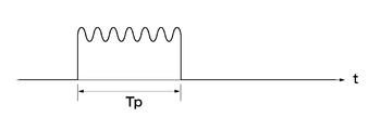
- the delay time of the optical delay generation unit 50 is set so that the difference in the light passage time is at least twice the pulse width Tp of the measurement transmission light mt generated by the light source unit 10.
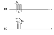
- the pulse light includes not only single pulse light but also a burst signal composed of a plurality of pulses (pulse width: Ts) as shown in FIGS. 11 and 14, for example.
- the pulse width Tp at this time is the burst length.
- a distance measuring apparatus 1 according to a fifth aspect of the present invention is the same as the distance measuring apparatus 1 according to any one of the second to fourth aspects. 5), as shown in (2) of FIG. 5, it is determined whether the Tr1 and the Tm are separated, the time difference between the first reference light r1 and the measurement received light mr is determined by the pulse width Tp of the pulsed light. Do by comparing to standards.
- the pulse light includes not only single pulse light but also a burst signal composed of a plurality of pulses (pulse width: Ts) as shown in FIGS. 11 and 14, for example.
- the pulse width Tp at this time is the burst length.
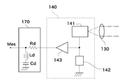
- a distance measuring apparatus 1 is the invention according to any one of the first to fifth aspects, as shown in FIG.
- the optical delay generator 50 is an optical fiber.
- the optical fiber when the optical fiber is used, the optical fiber can be small and the optical delay generator having a large delay time can be realized. Therefore, the entire distance measuring device can be miniaturized.
- the distance measuring apparatus 1 is the invention according to any one of the second aspect to the sixth aspect.
- the photoelectric conversion unit 140 has a resonance circuit unit 170 that converts a received pulsed light signal into a damped vibration waveform, and the time difference is determined based on zero crossing points t1, t2,. To decide.
- the position on the time axis of the zero-crossing point of the damped oscillation waveform has little change on the time axis of the optical signal even if the amplitude of the received optical signal fluctuates. Therefore, the influence of various disturbances is small. In addition, high accuracy can be obtained because the zero point that is less affected by fluctuations in offset voltage generated by electrical processing is used as a reference. In particular, since the first zero crossing point t1 after the start of vibration is more stable on the time axis than the other zero crossing points t2,..., Tn, the time difference is based on this zero crossing point t1. It is desirable to decide.
- the distance measuring method is, for example, as shown in FIG. 1, FIG. 4, FIG. 5, and FIG.
- a light source 10 that emits pulses in synchronization with the trigger signal Trg, a light separation unit 30 that branches light from the light source 10 into a first reference light r1, a second reference light r2, and a measurement transmission light mt;
- a first reference optical path R1 that allows the first reference light r1 to pass therethrough and does not cause an optical distance change; and an optical delay generator 50 that generates a temporal delay with respect to the first reference optical path R1.
- a reference optical path switching unit 60 having a function of passing one of the first reference optical path R1 and the second reference optical path R2, passing both, and blocking both.
- the constant light amount adjusting unit 90 (91 (see FIG. 2), 92), the output light of the first reference optical path R1, the output light of the second reference optical path R2, and the measurement received light mr received by the receiving unit 110r are combined.
- a distance measuring method using a distance measuring device 1 including a light combining unit 70 and a photoelectric conversion unit 140 that converts an optical signal combined by the light combining unit 70 into an electric signal is: (1) The reference light path switching unit 60 is controlled to pass through the first reference light path R1 and the second reference light path R2, and the measurement light amount adjusting unit 90 is controlled to block the measurement transmission light mt or the measurement reception light mr.
- Tr1 Measuring and storing the time difference (Tr1) between the trigger signal Trg and the first reference light r1 and the time difference (Tr2) between the trigger signal Trg and the second reference light r2 from the output of the photoelectric conversion unit 140 (S10); (2) The first reference optical path R1 and the second reference optical path R2 are blocked, and the measurement transmission light mt and the measurement reception light mr are passed, and the time difference (Tm) between the measurement reception light mr and the trigger signal Trg is measured.
- Second measurement for determining the measurement optical path difference (Tt) by obtaining Tm and further obtaining Td Tr2-Tr1 from the values of Tr2 and Tr1 obtained in (1) and calculating Td ⁇ Td ′.
- the measurement received light and the reference light can be separated on the time axis as in the long-distance measurement, so that the processing is simplified and high-accuracy measurement is possible.
- the measurement reception light and the reference light are not sufficiently separated on the time axis, such as near-field measurement, and high accuracy is not possible, the measurement reception light and the reference light can be separated by inserting a delay means.
- it is possible to cancel the passage time variation due to the temperature change of the delay means it is possible to measure with high accuracy.
- FIG. 1 is an overall configuration diagram of a distance measuring device according to a first embodiment of the present invention.
- Configuration with a measurement light intensity adjustment unit on the transmission side Configuration of transmitter / receiver using prism
- the figure which shows each part waveform of the measurement (far distance: case 1) by this invention The figure which shows each part waveform of the measurement (short distance: case 2) by this invention
- the figure which shows the measurement procedure of this invention Example of a resonant circuit for generating a damped vibration waveform Diagram showing input / output waveforms for generating damped vibration waves
- the figure explaining the optical pulse signal modulated with the chirp signal A diagram for explaining an amplitude-modulated light pulse Diagram explaining correlation detection of specific pattern Diagram explaining the principle of conventional measurement
- the light source unit 10 generates optical pulse light (measurement transmission light mt) at a constant timing based on the trigger signal Trg.
- the light source unit 10 includes a light emitting element 12 and a light emission drive circuit 11 that drives the light emitting element 12.
- the light-emitting element 12 is typically a semiconductor laser capable of irradiating a thin measurement beam 160 to a long-distance measurement object 160, but any LED that can measure the distance from the short-distance measurement object 160 is used.
- a non-coherent light source such as Here, a semiconductor laser, particularly a pulse laser diode will be described.
- the light emission drive circuit 11 drives a drive current to the light emitting element 12, and flows a current equal to or greater than a threshold only during a period during which light emission is desired. That is, a drive current is passed at a stroke at the moment when it is desired to emit light.
- the light emission drive circuit 11 generates a light emitting element drive pulse having a necessary pulse width based on the trigger signal. However, the drive pulse may be a single pulse, or a repetitive pulse having a predetermined cycle based on the trigger signal Trg. It may be.
- the light pulse generated by the light emitting element 12 is converted into a parallel light beam by the collimating lens 20.
- the light pulse converted into a parallel light beam by the collimator lens 20 is split by the light separation unit 30 into the measurement transmission light mt, the first reference light r1, and the second reference light r2.
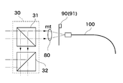
- the light separation unit 30 includes two beam splitters 31 and 32. That is, the parallel light beam from the collimating lens 20 is separated into two by the beam splitter 31, one light beam is used as the measurement transmission light mt, the other light beam is further divided into two by the beam splitter 32, and each of the first reference light beam r1.
- the measurement transmission light mt output from the beam splitter 31 is collected by the condenser lens 80 and input to the optical fiber 100 for connection to the transmission unit 110t.
- the measurement transmission light mt propagated in the optical fiber 100 is converted into a parallel light beam again by the collimator lens 111, the direction thereof is bent at a right angle by the light projection mirror 112, and a hole opened near the center of the objective lens 113. Irradiation toward the measurement object 160 through 113a.
- the light reflected by the measurement object 160 is collected by the objective lens 113 provided in the receiving unit 110r and input to the connection optical fiber 120.
- the light propagating through the optical fiber 120 is converted into a parallel light beam by the collimator lens 81.
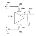
- FIG. 3 shows another embodiment of the transmission unit 110t / reception unit 110r. As shown in the figure, this embodiment is configured by inserting a prism 210 between the lens 180 and the lens 190 and between the lens 200 and the lens 190.
- a measurement light amount adjustment unit 90 (91, 92) is provided.
- the measurement light amount adjustment unit may be inserted on the transmission side or the reception side, but is preferably on the reception side. If the amount of light is changed on the transmission side, the amount of internal reflection noise due to surface reflections of optical components inside the device will change, making it difficult to obtain a stable distance measurement accuracy. This is because the amount of reflected noise is constant and stable ranging accuracy can be obtained. These give desired attenuation to the incident light, and are controlled by the measurement control unit 150.
- the amount of attenuation can be infinite, and if it is configured so that incident light can be completely blocked, it can also be used as a measuring light blocking means described later.
- the measurement light amount adjustment unit 90 (91, 92) is arranged at a position other than the position shown in FIG. 1 such as between the condenser lens 80 and the light separation unit 30 or between the collimator lens 81 and the light synthesis unit 70. May be.
- the first reference light r1 and the second reference light r2 separated by the beam splitter 32 are selected as reference light by the reference light path switching unit 60.
- the separated first reference light r1 and second reference light r2 are input to the first reference light path switch 61 and the second reference light path switch 62, respectively.
- the first reference optical path switching unit 61 and the second reference optical path switching unit 62 are controlled by the measurement control unit 150 and are configured to be able to execute either blocking or blocking incident light.
- the light that has passed through the first reference optical path switch 61 is input to the light combining unit 70 via the first reference optical path R1.
- the first reference optical path R1 is typically a simple space with a short optical path length. That is, the first reference optical path switching unit 61 and the light combining unit 70 are optically directly connected, and optical distance change hardly occurs.
- a short optical fiber that does not cause a practical change in distance can be used. For example, when the accuracy is 1 millimeter, the length of the optical fiber is about several tens of centimeters.
- the light that has passed through the second reference optical path switch 62 is input to the light combining unit 70 via the second reference optical path R2.
- An optical delay generator 50 is inserted in the second reference optical path R2.
- the optical delay generator 50 gives a difference in propagation time between the first reference optical path R1 and the second reference optical path R2, and is typically an optical fiber. More specifically, a graded index fiber.
- the lights respectively propagated through the first reference optical path R1 and the second reference optical path R2 are combined by the beam splitter 71 in the light combining unit 70, and the combined signal is adjusted in level by the reference light amount adjusting unit 93. Further, it is combined with the measurement received light mr by the beam splitter 72.
- the optical signal synthesized by the beam splitter 72 is condensed by the condenser lens 130 and is incident on the light receiving element 141 provided in the photoelectric conversion unit 140.
- the light receiving element 141 is typically an APD (avalanche photodiode), but other elements may be used as long as they sufficiently respond to the light pulse emitted from the light source unit 10 and have the necessary sensitivity.
- the detection output of the light receiving element 141 appears as an electrical signal at both ends of the load 142, is amplified by the preamplifier 143, and is output as the measurement output Mes.
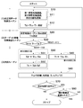
- this procedure includes (1) a calibration data acquisition routine, (2) a target (measuring object) approximate position detection routine, and (3) a distance measurement routine.
- the distance measurement routine is further divided into a first measurement and a second measurement according to the distance to the measurement object.
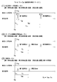
- step S10 a difference Td between the light passage times of the first reference optical path R1 and the second reference optical path R2 is obtained, and this value is stored.
- Step S10 includes steps S11 to S12.
- step S ⁇ b> 11 the first reference optical path switching unit 61 and the second reference optical path switching unit 62 are passed by the instruction of the measurement control unit 150, and the measured light amount adjustment unit 90 is shut off.
- step S12 the time difference Td between the first reference light r1 and the second reference light r2 is measured. In this way, the light from the light source unit 10 propagates through the first reference optical path R1 and the second reference optical path R2 and enters the photoelectric conversion unit 140, but does not propagate the measurement transmission light mt. .
- This state is shown in (1) of FIG. 4 and (1) of FIG. 4 and 5, Tr1 and Tr2 are measured based on the timing T0 of the trigger signal Trg.
- the measurement is not limited to this, and a constant time interval is maintained with the measurement transmission light mt. Just do it.
- processing based on the timing T0 of the trigger signal Trg can be processed as an electric signal, and there are few unstable elements, and highly accurate measurement can be performed. The following description is based on T0.
- FIG. 4 (1) and FIG. 5 (1) show output waveforms of the photoelectric conversion unit 140 of the first reference light r1 and the second reference light r2.
- the first reference light r1 and the second reference light r2 are received by the light receiving element 141, they are delayed by Tr1 and Tr2 from the reference time T0, respectively.
- Each pulse width is Tp (in the case where the output waveform of the light source unit is a burst signal composed of a set of a plurality of pulses, as will be described later).
- the first reference light r1 and the second reference light are received so that the first reference light r1 and the second reference light r2 are received at a fixed timing with reference to the time when the trigger signal Trg is input.
- Tr2 fluctuates due to a temperature change of the optical fiber as the optical delay generation unit 50 inserted in the second reference optical path R2. This fluctuation amount is assumed to be ⁇ Tr2.
- ⁇ Tr1 since the first reference optical path R1 does not include a large delay element, ⁇ Tr1 can be almost ignored.
- ⁇ Tr2 causes a measurement error.
- the present invention is characterized in that this error can be offset. This point will be described in detail later.
- the measurement light is transmitted through the measurement light path M through the measurement light amount adjustment unit 90, the first reference optical path R1 and the second reference optical path R2 are blocked, and the measurement reception light mr is observed by the photoelectric conversion unit 140.
- the reception timing Tm is measured (step S20).
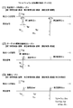
- Tm ⁇ Tr1 + Tp (Case 2) or Tm ⁇ Tr1 + Tp (Case 1) it is determined whether Tm ⁇ Tr1 + Tp (Case 2) or Tm ⁇ Tr1 + Tp (Case 1) (Step S30).
- Case 2 corresponds to a case where the distance between the measurement object 160 and the distance measuring device 1 is short, and is a case where the pulses of the measurement reception light mr and the first reference light r1 overlap in time.
- the waveform in such a case is shown in (2) of FIG. Case 1 corresponds to a case where the distance between the measurement object 160 and the distance measuring device 1 is long, and the pulses of the measurement reception light mr and the first reference light r1 do not overlap in time.
- the waveform in such a case is shown in FIG.
- Tt Tm ⁇ Tr1 (2)
- L cTt / 2 (3)
- c the speed of light.
- Case 2 corresponds to a case where measurement based on the first reference light r1 is impossible.
- the process of step S50 in FIG. 6 is executed. That is, the following calculation is performed using the time difference Td ′ between Tr2 and Tm and Td stored in the memory (steps S51 and S52).
- Td Tr2-Tr1 (4)
- Td ' Tr2-Tm (5)
- Tt Td ⁇ Td ′ (6)
- the distance L to the measurement object 160 is obtained using the equation (3) (step S ⁇ b> 60).
- measurement is performed with reference to the second reference light r2 having different transit times of the first reference light r1, thereby separating the overlapping of the pulses of the measurement reception light mr and the first reference light r1. I can do it.
- Tr1 is affected by fluctuations, as described above, Tr1 is set to have a short delay time, so that the influence of temperature change is small. Therefore, highly accurate measurement can be performed with almost no influence of temperature or the like.
- step S70 it is further determined whether or not the measurement environment has been changed in the next measurement (step S80).
- “change in measurement environment” refers to a case where the calibration data measured in step S10 changes due to a change in temperature, a change in the installation location of the distance measurement device, or the like. If such a change does not occur (“NO” in step S80), the process returns to step S20 and the measurement is repeated.
- the measurement environment fluctuates (“YES” in step S80)
- the process returns to step S10, Td as calibration data is measured again, and the stored measurement value is rewritten.
- step S10 Since it is such a structure, it is not necessary to implement step S10 for every measurement in every measurement. Therefore, quick measurement is possible.
- step S70 the flow of FIG. 6 is finished.
- step S80 can be omitted when the calibration data acquisition step is performed every measurement or when the calibration data acquisition process is omitted at every measurement.
- the determinations in step S70 and step S80 may be performed automatically according to a predetermined procedure, or may be performed manually every measurement.
- the level between the first reference light r1 and the second reference light r2 is that the propagation path is in the distance measuring device, so that an appropriate level adjusting means is provided in the first reference light path R1 or the second reference light path R2. There is no need to adjust according to the measurement environment.
- the level of the measurement reception light mr varies depending on the measurement environment such as the measurement distance L and the reflection condition of the measurement object 160. As shown in FIG. 1, in the present embodiment, a measurement light amount adjustment unit 92 is provided on the receiving side in order to absorb this variation.
- the actual measurement light amount adjustment unit 91 may be provided on the transmission side, or may be provided on both the transmission side and the reception side.
- the measurement light amount adjusting unit 90 for example, a mechanism that mechanically adjusts the ND filter or an electro-optical effect such as a liquid crystal transmission plate can be used. Note that, as in step S11 of FIG. 6, it is necessary to completely block the transmitted light because it is necessary to completely block the measurement optical path M.
- These controls are performed by the measurement control unit 150 based on the detection result of the level detection means (not shown). In addition to the above automatic control, there is a form of manual control.
- Td is the difference between the time required for the first reference light r1 and the second reference light r2 to pass through the respective optical paths, and the delay time setting value Tq of the substantially optical delay generator 50. However, it is slightly shifted due to the delay time of other parts of the distance measuring device. Even in such a case, in order to prevent the first reference light r1 and the second reference light r2 from overlapping in time and to determine Td with high accuracy, Tq is set to the pulse width Tp of the measured transmission light pulse. (In the case where one measurement transmission light is a burst light composed of n single pulses having a pulse width Ts as shown in FIG. 11 described later, Tp> nTs) is preferable.
- Tr1, Tr2, and Tm For the measurement of Tr1, Tr2, and Tm, a known technique for measuring the time difference ⁇ T between two pulses can be used. For example, in order to measure the time difference between the start signal M1 (pulse signal) and the stop signal M2 (pulse signal), two reference signals S1 and S2 having a phase difference of ⁇ / 2 are generated from a reference frequency generator and started.
- the phase difference ⁇ is detected, and the detected phase difference ⁇ and
- a method of calculating ⁇ T based on the period of the reference signals S1 and S2 for example, JP 2006-133214 A: pulse time difference method.
- FIG. 7 shows a configuration when the damped vibration wave zero-crossing method is applied.
- a resonance circuit 170 is connected to the output end of the photoelectric conversion unit 140.
- the resonance circuit 170 is typically a series or parallel circuit of a resistor Rd, an inductance Ld, and a capacitor Cd.
- Rd includes the output resistance of the preamplifier 143.
- FIG. 8 shows output waveforms of the photoelectric conversion unit 140 and the resonance circuit 170.
- a damped oscillation waveform is obtained for the single pulse shown in FIG.
- a broken line indicates a case where the peak value fluctuates (increases).
- the zero crossing points t1 to Tn do not fluctuate even if the peak value fluctuates. Therefore, if the time difference between the reference time point and the zero crossing point t1 that is most stable in terms of waveform is measured, a highly accurate measurement can be performed.
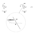
- FIG. 10 shows a case where two damped vibration waves are present close in time. For example, the time difference between the first reference light r1 and the measurement reception light mr is obtained. As described above, it is possible to measure with high accuracy by detecting the zero crossing point of the damped vibration wave. However, if there is an interference wave in the vicinity of this zero crossing point, a measurement error of the timing of the zero crossing point occurs. Accordingly, when the decay of the decay waveform of the first reference light r1 continues until near the zero crossing point of the measurement reception light mr as shown in FIG. 10, the measurement reception is performed so that the afterglow component of the first reference light r1 is sufficiently attenuated.
- the first period of the measurement received light mr is approximated by a sine wave having an amplitude level S (voltage display) and a frequency fs.
- the frequency fs is the resonance frequency of the resonance circuit 170.
- the measurement distance errors ⁇ Ls and (N / S) due to the interference wave are as follows. There is a relationship.
- the above is the result when the first reference light r1 is used, but similar interference occurs when the second reference light r2 is used. Since the distance measurement range when using the first reference light r1 is set to 50 m or more, the measurement light is closest to the second reference light r2 in time when the measurement object 160 exists at a distance of 50 m. is there. Therefore, in the case where measurement is performed using the second reference light r2 (case 1 in FIG. 4), the necessary optical distance is required in order to make the influence of the interference wave negligible (N / S ⁇ 1/800). Needs to be set to 100m with 50m added. Since the optical distance 100 m is a value obtained by converting the round trip of light as a measurement distance, the distance that light actually travels is 200 m.
- the optical delay generator 50 when the optical delay generator 50 is realized by an optical fiber, the physical length is 130 m in consideration of the refractive index (1.5) of the optical fiber.
- the accuracy is improved, but a large delay generation unit is required, and the variation of the delay time due to temperature or the like becomes large. Even in such a case, if the present invention is applied, the passage time fluctuation is canceled out, so that highly accurate measurement can be maintained.
- the pulse width Tp ′ of the optical pulse signal converted into the electric signal is wider than the pulse width Tp of the measurement transmission light mt. Accordingly, among the descriptions related to the pulse width Tp described so far, the duration of the damped oscillation Tp ′ is used for the received light pulse width instead of Tp in the case of a single pulse.
- Tp ′ is determined by the attenuation constant ⁇ and the pulse width Tp of the measurement transmission light mt.
- the transmission measurement light mt is a single pulse.
- the single pulse there are embodiments as shown in FIGS.
- FIG. 11A shows a case where a light pulse (pulse width: Tp) is a burst-like pulse in which a plurality of single pulses (pulse width: Ts) are continuously continued.
- FIG. 11 (b) shows a case where each single pulse continues with different pulse widths Ts1, Ts2, and Tsn in the case of the burst-like pulse of FIG. 11 (a).
- FIG. 12 shows an optical pulse modulated with a chirp signal.
- the chirp signal is a signal whose frequency continuously changes over time.
- FIG. 13 shows an optical pulse whose amplitude is modulated.
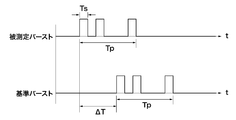
- FIG. 14 shows a case where one light pulse is constituted by a code having a specific pattern.
- the detection times of the received measurement light mr and the reference lights r1 and r2 can be accurately measured.
- DESCRIPTION OF SYMBOLS 1 Distance measuring device 10 Light source part 11 Light emission drive circuit 12 Light emitting element 20 Collimator lens 30 Light separation part 31 Beam splitter 32 Beam splitter 50 Optical delay generation unit 60 Reference optical path switching unit 61 First reference optical path switching unit 62 Second reference optical path switching unit 70 Light combining unit 71 Beam splitter 72 Beam splitter 80 Condensing lens 81 Collimating lens 90 Measurement light quantity Adjustment unit 91 Measurement light quantity adjustment unit (transmission side) 92 Measurement light intensity adjustment unit (reception side) 93 Reference light amount adjusting unit 100 Optical fiber 104 Photodetector 110r Receiving unit 110t Transmitting unit 111 Collimating lens 112 Projecting mirror 113 Objective lens 113a Hole (objective lens) 120 optical fiber 130 condensing lens 140 photoelectric conversion unit 141 light receiving element 143 preamplifier 150 measurement control unit 160 measurement object 170 resonance circuit 180 lens 190 lens 200 lens 210 prism Cont control signal M measurement optical path Mes measurement output mr
Abstract
距離測定装置内部の遅延回路の変動を相殺し、高精度でかつ高速測定が可能な距離測定装置及び方法を実現する。 パルス的に発光する光源部10から、第1基準光r1、第2基準光r2、測定送信光mtを分岐し、光学的変化が略生じない第1参照光路R1を伝播させた第1基準光r1、光学的遅延発生部50が挿入された第2参照光路を伝播した第2基準光r2、測定送信光を測定対象物160に照射して反射して戻ってきた測定受信光mr間の検出時間差を測定することによって測定対象物160との距離を測定する装置及び方法であって、測定受信光mrと第1基準光r1が時間的に分離している場合は、両者の検出時間差から距離を算出し、測定受信光mrと第1基準光r1が時間的に分離していない場合は、第1基準光r1と第2基準光r2の検出時間差Tdと、測定受信光mrと第2基準光r2の検出時間差Td'から距離Lを算出する。
Description
本発明は、測定対象物に光パルスを照射し、その反射光が戻るまでの時間を測定することにより測定対象物との距離を測定する距離測定装置及び方法に関する。特に、参照光路に遅延要素を含む測定方式を採用した距離測定装置において、当該遅延要素の遅延時間の温度変動等の影響をキャンセルし、高精度な測定が可能な距離測定装置及び方法に関する。
従来、測定対象物に向かってパルス光を照射し、その測定対象物から反射されたパルス光を距離測定装置で検出し、そのパルス光の往復の伝播時間から測定対象物までの距離を測定する技術がある。
このような距離測定装置では、出来るだけ精度の高い測定を行うため、距離測定装置内の電気的な変動の影響を受けないように、光処理段階で伝播時間が決定される方式が採用される。例えば、図15のように、距離測定装置100にパルス光源101、パルス光源101から分岐された参照光路Rc、光検出器104を設け、参照光路Rcでの光パルス到達時間を基準に測定対象物160までの測定光路Mcとの伝播時間差を光検出器104で検出し、これから距離Lを測定する方式である。ここで、参照光路Rcと測定光路Mcは光路切換器103a,103bで機械的に切り換えて、光路Rc,Mcの各々を経由したパルス光の伝播時間を時間的に別のタイミングで独立に測定し、測定結果から伝播時間差を算出することが行われている。しかし、この方法は高速な動作が難しく、測定時間の短縮が制限される大きな要因となっていた。
この問題を解決する方法の一つとして、参照光路Rcを経由した光(参照光rc)と測定光路Mcを経由した光(測定光mc)を切り換えることなく、参照光rcと測定光mcを合成して一つの光検出器で検出する方法が考えられるが、測定対象物160と距離測定装置100との距離が短い場合参照光rcと測定光mcが時間軸上で重なってしまい、参照光rcと測定光mcの時間差を正確に検出することが困難となる(図15(b)ケース1参照)。そこで、予めその遅延時間が正確に分かっている光学的遅延発生器を参照光路Rcあるいは測定光路Mcに挿入し、測定光mcと参照光rcを時間軸上で分離してその時間差を測定し、然る後に光学的遅延発生器の遅延時間の値で測定された時間差を修正する方法がある(図15(b)ケース2参照、例えば、特許文献1)。
また、パルス光源101を駆動する際、発光する瞬間の大きな電流変化によって光検出器104の電気出力側に電磁誘導雑音が発生する。参照光路Rcの通過時間が短いと、この誘導雑音が参照光rcと時間軸上で重なり、測定誤差を生じることがある。これを回避するため、参照光路Rcに一定の遅延時間を有する遅延要素を加え、参照光rcと測定光mcを分離する例がある(例えば、特許文献2)。
通常、パルス光源101のパルス幅は10n秒程度のものが使用されることが多いが、この10n秒の遅延を発生させるためには遅延要素(屈折率1.5の光ファイバを用いた場合)の長さが最低でも2メートルは必要となる。実際には余裕を考えて遅延時間を設定するのでパルス幅の数倍以上の遅延時間とするのが望ましい。遅延時間として仮に一桁以上の100n秒を得ようとすると、遅延要素として光ファイバを用いた場合約20メートルの長さとなる。更に、後述する、減衰振動波形による零点検出による高精度な時間差測定方法を採用した場合、雑音レベルを-58dB(1/800)以下程度とすることが望ましく、その場合は、遅延要素として光学的距離換算で200メートル以上という長尺のものが必要となる。
上記遅延要素としては、自由に曲げることが可能で、小さな形状で大きな遅延時間が得られるために光ファイバが適する。しかし、光ファイバは、その伝播遅延時間が温度によって変化する特性を持っている。石英ファイバの屈折率の温度係数は10ppm/℃程度であり(例えば、非特許文献1、非特許文献2)、ファイバ長として、上記200メートル相当の遅延時間が得られる130メートルを用い、屋外での温度変化量を50℃とした場合、遅延時間の変化による測定距離の誤差は10cm程度となる。この誤差は1mm程度の測定精度を目的とする精密距離測定装置の誤差としては許容できない。
I.H.Malitson; "Interspecimen Comparisonof the Refractive Index of Fused Silica", Journal of the Optical Societyof America, vol.55, no.10, pp.1205(oct. 1965)
Gorachaud Ghosh; "TemperatureDispersion of Refractive Indexes in some Silicate Fiber Glasses", IEEEPHOTONICS TECHNOGY LETTERS, vol.6, no.3, pp.431(Mar. 1994)
本発明は、上記問題を解消し、距離測定装置内部の遅延回路の変動の影響を相殺し、高精度でかつ高速測定が可能な距離測定装置及び方法を実現することを目的とする。
上記目的を達成するため、本発明の第1の観点にかかる距離測定装置1は、例えば、図1に示すように、トリガ信号Trgに同期してパルス的に発光する光源部10と、光源部10からの光を第1基準光r1と第2基準光r2と測定送信光mtに分岐する光分離部30と、第1基準光r1を通過させ、光学的距離変化が生じない第1参照光路R1と、第1参照光路R1に対して大きな時間的な遅延を発生させる光学的遅延発生部50を含み、第2基準光r2を通過させる第2参照光路R2と、第1参照光路R1及び第2参照光路R2のどちらか一方を通過にし、両方を通過にし、及び、両方を遮断にする機能を有する参照光路切換部60と、測定送信光mtを測定対象物160に対して照射する送信部110tと、照射された測定送信光mtの測定対象物160で反射された測定受信光mrを受信する受信部110rと、測定送信光mt又は測定受信光mrを遮断する測定光量調整部90(91(図2参照),92)と、第1参照光路R1の出力光、第2参照光路R2の出力光、及び受信部110rで受信された測定受信光mrを合成する光合成部70と、光合成部70で合成された光信号を電気信号に変換する光電気変換部140と、制御信号CONTにより参照光路切換部60、測定光量調整部90を制御し、光電気変換部140で得られた信号の検出時間を基に距離を決定する機能を有する測定制御部150とを備える。
ここにおいて、「トリガ信号Trgに同期してパルス的に発光」とは、トリガ信号Trgのタイミングに基づきその発光タイミングが決定されることであり、言い換えれば、トリガ信号Trgのタイミングと発光するタイミングの間の時間に一定の関係があればよい。「パルス的に発光」とは、単発のパルス、繰り返しパルスの双方を含み、連続光でないことを指す。「発光」は、可視光、非可視光を含む光の発生である。「光源」は、レーザ光線のようなコヒーレント光、LED等から出射されるような非コヒーレント光の全てを含む。「光学的距離変化が生じない第1参照光路」とは、温度等の測定環境の想定される変化に対して、第1参照光路で生じる通過時間の変化が距離測定装置の測定精度に比べて無視できる程に小さいことを言う。「実用上精度に影響を生じない」あるいは「略生じない」と言ってもよい。例えば、1mm程度の測定精度が要求される場合、測定環境の変化に対して、測定精度の1/10の0.1mm程度の変化を言う。「通過」とは、入射した光エネルギーの全部または一部を通過させることを言う。「遮断」とは、入射した光エネルギーの全部を通過させないことである。「送信部」とは、距離測定装置1から測定対象物160に対して測定送信光mtをビーム状にして出射する部分であり、「受信部」とは、測定対象物160で反射され距離測定装置1に戻ってきた測定受信光mrを光電気変換部140に導くための部分である。送信部、受信部は、双方が共通の部分を持って構成されることがある。例えば、図1でレンズ113は、送信部110tの一部でもあり、受信部110rの一部である。
このように、第1及び第2の基準光、測定送信光、受信測定光の遮断/通過が独立に制御できるようになっているので、次に述べる第2の観点以下の発明を実施することができるユーティリティの高い測定プラットフォームを提供することができる。また、第1及び第2の基準光のみの測定を行う際、測定対象物への視準を行ったまま測定を行うことができ、距離算出のための測定受信光測定時に近い条件で測定を行うことができる。すなわち、第1及び第2の基準光のみを測定するために視準状態を解除して受信測定光を受光しないようにする必要がない。
上記目的を達成するため、本発明の第2の観点にかかる距離測定装置1の測定制御装置150は、例えば、図1及び図4、図5に示すように、第1の観点による距離測定装置において、
(1)参照光路切換部60を制御して第1の参照光路R1と第2の参照光路R2を通過とし、測定光量調整部90(91(図2参照),92)を制御して測定送信光mt又は測定受信光mrを遮断し、光電気変換部140の出力からトリガ信号Trgと第1基準光r1の時間差(Tr1)、トリガ信号Trgと第2基準光r2の時間差(Tr2)を測定して記憶する機能を有し、
(2)第1参照光路R1及び第2参照光路R2を遮断し、かつ、測定送信光mt及び測定受信光mrを通過とし、測定受信光mrとトリガ信号Trgとの時間差(Tm)を測定する機能を有し、
(3)第1参照光路R1を通過、第2参照光路R2を遮断、測定送信光mt及び前記測定受信光mrを通過とし、測定受信光mtと第1基準光r1との時間差(Tm-Tr1)の値によって測定光路差(Tt)を決定する第1の測定機能を有し、
(4)第1参照光路R1を遮断、第2参照光路R2を通過、前記測定送信光mt及び測定受信光mrを通過とし、第2基準光r2と測定受信光mrとの時間差Td’=Tr2-Tmを求め、更に、上記(1)で求めたTr2,Tr1の値から、Td=Tr2-Tr1を求め、Td-Td’を計算することによって測定光路差(Tt)を決定する第2の測定機能を有し、
(5)前記(2)で得られた前記時間差Tmに基づいて前記第1の測定機能と前記第2の測定機能とを使い分ける機能を有し、
(6)前記測定光路差(Tt)から測定対象物160までの距離を決定する機能を有する。
このように構成されているので、近距離から遠距離に亘る広い距離範囲で、精度の高い測定が可能となる。即ち、遠距離測定のような、測定受信光と基準光の時間軸上での分離が可能な場合は遅延手段を挿入することなく測定を行うので処理が単純となり高い精度の測定が可能となる。また、近距離測定のような、測定受信光と基準光が時間軸上での分離が十分でなく、高い精度が不可能な場合は遅延手段を挿入することにより測定受信光と基準光の分離を行うと共に、上記遅延手段の温度変化等による遅延時間変動を相殺することが出来るので高い精度の測定が可能となる。
上記目的を達成するため、本発明の第3の観点にかかる距離測定装置1は、例えば、図1及び図4、図5に示すように、第1の観点による距離測定装置において、測定光量調整部90が、更に測定受信光mr又は測定送信光mtを減衰させる機能を有し、測定受信光mrのレベルを第1基準光r1、及び、第2基準光r2のレベルに概ね合せる機能を有する。
ここにおいて、測定光量調整部90の調整対象は、測定送信光mt、測定受信光mr、又はその双方のレベルの調整を含む。尚、測定光量調整部90を挿入する箇所は図1に示す受信側に設けた測定光量調整部91に限定されず、図2のように送信側に設けた測定光量調節部91であっても良い。即ち、測定受信光mrのレベル制御が可能であれば距離測定装置の他の部分であってもよい。「レベルを概ね合せる」とは、測定受信光mr、第1基準光r1、及び、第2基準光r2の各パルスのレベル差による測定誤差を防ぎ、時間的位置が精度良く測定できる程度にレベルを合わせるという意味である。
このように構成されているので、参照光路を伝播してきた基準光r1、r2と受信光mrの時間的間隔が精度よく測定することができる。
上記目的を達成するため、本発明の第4の観点にかかる距離測定装置1は、上記第1の観点又は第2の観点にかかる発明において、第1参照光路R1と前記第2参照光路R2との光の通過時間の差が光源部10で発生する測定送信光mtのパルス幅Tpの2倍以上になるように光学的遅延発生部50の遅延時間が設定されている。尚、ここで、前記パルス光とは、単発のパルス光だけでなく、例えば、図11、図14に示すように複数のパルス(パルス幅:Ts)から成るバースト信号を含む。このときのパルス幅Tpはバースト長である。
このように設定すると、第1参照光路R1と第2参照光路R2を切り換えることなく第1基準光r1と第2基準光r2の双方を一つの光電気変換部140に入力しても第1基準光r1と第2基準光r2を時間的に分離可能となるため、Tr1とTr2の時間差を高い測定精度で測定することが出来る。
上記目的を達成するため、本発明の第5の観点にかかる距離測定装置1は、上記第2の観点乃至第4の観点のいずれか1の観点にかかる発明において、例えば、図4の(2)、図5の(2)に示すように、前記Tr1と前記Tmとが分離しているかの判断を、第1基準光r1と測定受信光mrとの時間差を前記パルス光のパルス幅Tpを基準に比較することによって行う。尚、ここで、前記パルス光とは、単発のパルス光だけでなく、例えば、図11、図14に示すように複数のパルス(パルス幅:Ts)から成るバースト信号を含む。このときのパルス幅Tpはバースト長である。
このように構成されていると、送信光mtのパルス幅Tpが光源部10の特性変動によって変わっても、参照光路切換部60での切換えを適切に行うことが出来、高い測定精度を確保することが出来る。
上記目的を達成するため、本発明の第6の観点にかかる距離測定装置1は、上記第1の観点乃至第5の観点のいずれか1の観点にかかる発明において、例えば、図1に示すように、光学的遅延発生部50が光ファイバである。
このように、光ファイバを用いれば、光ファイバは小さく巻き込むことにより小型で遅延時間の大きな光学的遅延発生部を実現出来るので、距離測定装置全体を小型にすることが出来る。
上記目的を達成するため、本発明の第7の観点にかかる距離測定装置1は、上記第2の観点乃至第6の観点のいずれか1の観点にかかる発明において、例えば、図7、図8に示すように、光電気変換部140は、受光したパルス光信号を減衰振動波形に変換する共振回路部170を有し、前記時間差を該減衰振動波形の零交差点t1,t2,…tnを基に決定する。
減衰振動波形の零交差点の時間軸上の位置は受光した光信号の振幅に揺らぎがあっても光信号の時間軸上の変化は少ない。従って、各種の撹乱の影響が少ない。また電気的処理で発生するオフセット電圧の変動等の影響が少ない零点を基準としているので高い精度を得る事が出来る。特に振動開始後一番最初の零交差点t1は他の零交差点t2,・・・,tnと比較して、より時間軸上の位置が安定しているので前記時間差はこの零交差点t1を基に決定することが望ましい。
上記目的を達成するため、本発明にかかる距離測定方法は、例えば、図1、図4、図5、図6に示すように、
トリガ信号Trgに同期してパルス的に発光する光源部10と、光源部10からの光を第1基準光r1と第2基準光r2と測定送信光mtに分岐する光分離部30と、第1基準光r1を通過させ、光学的距離変化が生じない第1参照光路R1と、第1参照光路R1に対して時間的な遅延を発生させる光学的遅延発生部50を含み第2基準光r2を通過させる第2参照光路R2と、第1参照光路R1及び第2参照光路R2のどちらか一方を通過にし、両方を通過にし、及び、両方を遮断にする機能を有する参照光路切換部60と、測定送信光mtを測定対象物160に対して照射する送信部110tと、照射された光の測定対象物160で反射された測定受信光mrを受信する受信部110rと、測定送信光mt又は測定受信光mrを遮断する測定光量調整部90(91(図2参照),92)と、第1参照光路R1の出力光、第2参照光路R2の出力光、及び受信部110rで受信された測定受信光mrを合成する光合成部70と、光合成部70で合成された光信号を電気信号に変換する光電気変換部140と、を備える距離測定装置1を使用した距離測定方法であって、
該距離測定方法は、
(1)参照光路切換部60を制御して第1の参照光路R1と第2の参照光路R2を通過とし、測定光量調整部90を制御して測定送信光mt又は測定受信光mrを遮断し、光電気変換部140出力からトリガ信号Trgと第1基準光r1の時間差(Tr1)、トリガ信号Trgと第2基準光r2の時間差(Tr2)を測定して記憶する工程(S10)と、
(2)第1参照光路R1及び第2参照光路R2を遮断し、かつ、測定送信光mt及び測定受信光mrを通過とし、測定受信光mrとトリガ信号Trgとの時間差(Tm)を測定する工程(S20)と、
(3)第1参照光路R1を通過、第2参照光路R2を遮断、測定送信光mt及び測定受信光mrを通過とし、測定受信光mrと第1基準光r1との時間差(Tm-Tr1)の値によって測定光路差(Tt)を決定する第1の測定工程(S40)と、
(4)第1参照光路R1を遮断、第2参照光路R2を通過、測定送信光mt及び測定受信光mrを通過とし、第2基準光r2と測定受信光mrとの時間差Td’=Tr2-Tmを求め、更に、上記(1)で求めたTr2,Tr1の値から、Td=Tr2-Tr1を求め、Td-Td’を計算することによって測定光路差(Tt)を決定する第2の測定工程(S50)と、
(5)上記(2)で得られた前記時間差Tmに基づいて第1の測定工程(S40)と第2の測定工程(S50)とを使い分ける工程(S30)と、
(6)前記測定光路差(Tt)から測定対象物160までの距離を決定する工程(S60)とを有する。
このように構成されているので、近距離から遠距離に亘る広い距離範囲で、精度の高い測定が可能となる。即ち、遠距離測定のような、測定受信光と基準光の時間軸上での分離が可能な場合は遅延手段を挿入することなく測定を行うので処理が単純となり高い精度の測定が可能となる。また、近距離測定のような、測定受信光と基準光が時間軸上での分離が十分でなく、高い精度が不可能な場合は遅延手段を挿入することにより測定受信光と基準光の分離を行うと共に、上記遅延手段の温度変化等による通過時間変動を相殺することが出来るので高い精度の測定が可能となる。
この出願は、日本国で2008年12月25日に出願された特願2008-330162号に基づいており、その内容は本出願の内容として、その一部を形成する。本発明は以下の詳細な説明によりさらに完全に理解できるであろう。本発明のさらなる応用範囲は、以下の詳細な説明により明らかとなろう。しかしながら、詳細な説明及び特定の実例は、本発明の望ましい実施の形態であり、説明の目的のためにのみ記載されているものである。この詳細な説明から、種々の変更、改変が、本発明の精神と範囲内で、当業者にとって明らかであるからである。出願人は、記載された実施の形態のいずれをも公衆に献上する意図はなく、改変、代替案のうち、特許請求の範囲内に文言上含まれないかもしれないものも、均等論下での発明の一部とする。
以下、図面を参照して、本発明の実施の形態について説明する。尚、各図において、互いに同一又は相当する部分には同一符号を付し,重複した説明は省略する。
[距離測定装置の構成例]
図1を参照して、本発明の第1の実施の形態としての距離測定装置1について説明する。光源部10はトリガ信号Trgを基に一定のタイミングで光パルス光(測定送信光mt)を発生する。光源部10は、発光素子12と発光素子12を駆動する発光用駆動回路11で構成される。発光素子12は典型的には、遠距離の測定対象物160に対しても細い光ビームを照射できる半導体レーザであるが、近距離の測定対象物160との距離を測定するものであればLEDのような非コヒーレントな光源でもよい。ここでは半導体レーザ、特にパルスレーザダイオードの場合、で説明する。発光用駆動回路11は発光素子12に駆動電流をドライブするもので、発光させたい期間だけ閾値以上の電流を流す。即ち、発光させたい瞬間に駆動電流を一気に流す。発光用駆動回路11ではトリガ信号を基に必要なパルス幅の発光素子駆動パルスを生成するが、駆動パルスは単一パルスであっても良く、またトリガ信号Trgに基づいて所定の周期の繰り返しパルスであってもよい。発光素子12で発生した光パルスはコリメートレンズ20で平行光束に変換される。
図1を参照して、本発明の第1の実施の形態としての距離測定装置1について説明する。光源部10はトリガ信号Trgを基に一定のタイミングで光パルス光(測定送信光mt)を発生する。光源部10は、発光素子12と発光素子12を駆動する発光用駆動回路11で構成される。発光素子12は典型的には、遠距離の測定対象物160に対しても細い光ビームを照射できる半導体レーザであるが、近距離の測定対象物160との距離を測定するものであればLEDのような非コヒーレントな光源でもよい。ここでは半導体レーザ、特にパルスレーザダイオードの場合、で説明する。発光用駆動回路11は発光素子12に駆動電流をドライブするもので、発光させたい期間だけ閾値以上の電流を流す。即ち、発光させたい瞬間に駆動電流を一気に流す。発光用駆動回路11ではトリガ信号を基に必要なパルス幅の発光素子駆動パルスを生成するが、駆動パルスは単一パルスであっても良く、またトリガ信号Trgに基づいて所定の周期の繰り返しパルスであってもよい。発光素子12で発生した光パルスはコリメートレンズ20で平行光束に変換される。
コリメートレンズ20により平行光束になった光パルスは光分離部30によって、測定送信光mt、第1基準光r1、第2基準光r2に分割される。光分離部30は例えば、二つのビームスプリッタ31,32で構成される。即ち、コリメートレンズ20からの平行光束をビームスプリッタ31で2つに分離し、一方の光束を測定送信光mtとし、他方の光束をビームスプリッタ32で更に2分割し、各々を第1基準光r1、第2基準光r2とする。ビームスプリッタ31から出力された測定送信光mtは、集光レンズ80で集光され、送信部110tに接続するための光ファイバ100に入力される。
送信部110tでは、光ファイバ100内を伝播した測定送信光mtをコリメートレンズ111で再び平行光束とし、投光ミラー112でその方向を直角方向に曲げ、対物レンズ113の中心付近に開けられた孔113aを通じて測定対象物160に向けて照射する。
測定対象物160で反射された光は、受信部110rに設けた対物レンズ113で集光され、接続用光ファイバ120に入力される。光ファイバ120内を伝播した光はコリメートレンズ81で平行光束とされる。
図3に、送信部110t/受信部110rの他の実施の形態を示す。図のように本実施の形態は、レンズ180とレンズ190の間、及びレンズ200とレンズ190の間にプリズム210を挿入して構成したものである。
再び、図1に戻り説明を続ける。集光レンズ80と光ファイバ100の間(送信側)、又はコリメートレンズ81と光ファイバ120の間(受信側)には、測定光量調整部90(91,92)が設けられている。測定光量調整部の挿入場所は送信側でも受信側でも良いが、受信側の方が良い。送信側で光量を変化させると装置内部の光学部品の表面反射などによる内部反射ノイズの量が変化し、安定した測距精度を得るための方法が難しくなるが、受信側に設けると、その内部反射ノイズの量が一定となり、安定した測距精度を得ることができるからである。これらは入射した光に対して所望の減衰を与えるものであり、測定制御部150により制御される。減衰量は無限大まで可能であり、入射した光を完全に遮断することが出来るように構成すると後で説明する測定光の遮断手段としても使用できる。また、測定光量調整部90(91,92)の配置位置は集光レンズ80と光分離部30の間や、コリメートレンズ81と光合成部70の間のように図1で示した位置以外に配置してもよい。
ビームスプリッタ32で分離された第1基準光r1及び第2基準光r2は参照光路切換部60で基準光として選択される。例えば、図1に示すように、分離された第1基準光r1及び第2基準光r2は各々、第1参照光路切換器61及び第2参照光路切換器62に入力される。第1参照光路切換器61及び第2参照光路切換器62は測定制御部150で制御され、入射した光を通過させるか遮断するかのいずれかを実行することが出来るように構成されている。
第1参照光路切換器61を通過した光は第1参照光路R1を経由して光合成部70に入力される。第1参照光路R1は典型的には光路長の短い単なる空間である。即ち、第1参照光路切換器61と光合成部70は光学的には直結であり、光学的な距離変化が略生じない。尚、第1参照光路R1には、距離変化が実用的に生じない程度の短い光ファイバを用いることが出来る。その長さは、例えば、1ミリメートルの精度の場合、光ファイバの長さとしては数十センチ程度である。
第2参照光路切換器62を通過した光は第2参照光路R2を経由して光合成部70に入力される。第2参照光路R2には光学的遅延発生部50が挿入されている。光学的遅延発生部50は、第1参照光路R1と第2参照光路R2の伝播時間に差を与えるもので、典型的には光ファイバである。更に具体的には、グレーテッド・インデクス・ファイバである。
第1参照光路R1及び第2参照光路R2を各々伝播してきた光は、光合成部70内のビームスプリッタ71で合成され、合成された信号は基準光量調整部93でそのレベルを調整された後、更にビームスプリッタ72で測定受信光mrと合成される。
ビームスプリッタ72で合成された光信号は集光レンズ130で集光され光電気変換部140内に設けた受光素子141に入射される。受光素子141は、典型的にはAPD(アバランシェフォトダイオード)であるが、光源部10から出射する光パルスに十分応答し、必要な感度を有するものであれば他の素子を用いても良い。受光素子141の検出出力は負荷142の両端に電気信号として現れ、プリアンプ143で増幅され、測定出力Mesとして出力される。
図6の測定手順と適宜図4、図5を用いて、本距離測定装置1の動作を説明する。図6のように、本手順は、(1)校正用データ取得ルーチン、(2)ターゲット(測定対象物)概略位置検出ルーチン、(3)測距ルーチンから成る。測距ルーチンは、更に測定対象物までの距離に応じて、第1の測定、及び第2の測定に分かれる。まず、図6において、ステップS10で、第1参照光路R1と第2参照光路R2の光の通過時間の差Tdを求め、この値を記憶する。ステップS10はステップS11~ステップS12から成る。ステップS11では、測定制御部150の指令により第1参照光路切換器61を通過および第2参照光路切換器62を通過、測定光量調整部90を遮断とする。次に、ステップS12で第1基準光r1と第2基準光r2の時間差Tdを測定する。このようにして、光源部10からの光は第1参照光路R1及び第2参照光路R2を伝播して光電気変換部140に入射するようにするが、測定送信光mtは伝播しないようにする。この様子を図4の(1)と図5の(1)に示す。尚、図4、図5ではTr1、Tr2をトリガ信号TrgのタイミングT0を基準に測定しているが、これに限定されるわけではなく、測定送信光mtと一定の時間的間隔が保たれていれば良い。但し、トリガ信号TrgのタイミングT0を基準にした方が、電気信号として処理ができ、不安定要素が少なく、精度の高い測定が行える。以下の説明はT0を基準にして行う。
図4の(1)及び図5の(1)に、第1基準光r1及び第2基準光r2の光電気変換部140の出力波形を示す。第1基準光r1及び第2基準光r2が受光素子141で受光された時、各々、基準時点T0から、Tr1,Tr2だけ遅延している。各々のパルス幅はTp(尚、後述するように、光源部の出力波形が複数のパルスの集合からなるバースト信号の場合はバースト幅)である。図6のステップS12で、トリガ信号Trgが入力される時間を基準として一定のタイミングで第1基準光r1及び第2基準光r2が受光されるように、第1基準光r1及び第2基準光r2の光源部10の出力タイミングが測定される。測定送信光mt発生タイミングトリガ信号Trg入力タイミングT0と同期しているが、一定の時間遅れがある場合が一般的である。この様な場合でも、光源部10の出力の立ち上がりタイミングとトリガ信号Trg入力時点T0の時間間隔は一定に保たれている。従って、トリガ信号Trgの入力時点T0を基準(以下、基準時点T0と言う)として、第1基準光r1及び第2基準光r2の伝播時間Tdを決定することが出来る。即ち、
Td=Tr2-Tr1 (1)
Tdの値、及びTr1を制御部150のメモリに格納する。
Td=Tr2-Tr1 (1)
Tdの値、及びTr1を制御部150のメモリに格納する。
Tr2の値は第2参照光路R2に挿入された光学的遅延発生部50としての光ファイバの温度変化等により変動する。この変動量をΔTr2とする。一方、第1参照光路R1には大きな遅延要素が含まれないのでΔTr1は殆ど無視することができる。ΔTr2は測定誤差の要因となるものであるが、本発明では、この誤差を相殺できる点に特徴を有する。この点について、後に詳しく説明する。
次に、測定光量調整部90を通過として測定光路Mに測定光を伝播させ、第1参照光路R1、及び第2参照光路R2を遮断として、測定受信光mrを光電気変換部140で観測し、受信タイミングTmを測定する(ステップS20)。Tmの値とS10で記録したTr1及びパルス幅Tpを用い、Tm<Tr1+Tpであるか(ケース2)、Tm≧Tr1+Tpであるか(ケース1)を判断する(ステップS30)。ケース2の場合は、測定対象物160と距離測定装置1との距離が短い場合に相当し、測定受信光mrと第1基準光r1のパルスが時間的に重なる場合である。このような場合の波形を図5の(2)に示す。ケース1の場合は、測定対象物160と距離測定装置1との距離が長い場合に相当し、測定受信光mrと第1基準光r1のパルスが時間的に重なっていない。このような場合の波形を図4の(2)に示す。
ステップS30での比較の結果、ケース1に該当する場合、以下の式(2)により、Ttを算出する(ステップS40)。
Tt=Tm-Tr1 (2)
上記、Ttより、次式により、測定対象物160までの距離Lを求める(ステップS60)。
L=cTt/2 (3)
ここで、cは光速である。
Tt=Tm-Tr1 (2)
上記、Ttより、次式により、測定対象物160までの距離Lを求める(ステップS60)。
L=cTt/2 (3)
ここで、cは光速である。
ケース2に該当する場合は、第1基準光r1を基準にした測定が不可能な場合である。このような場合は、図6のステップS50の処理を実行する。即ち、Tr2とTmの時間差Td’、及び、メモリに格納されたTdを用いて以下の演算を実施する(ステップS51,S52)。
Td=Tr2-Tr1 (4)
Td’=Tr2-Tm (5)
Tt=Td-Td’ (6)
次に、ケース1の場合と同様に、式(3)を用いて測定対象物160までの距離Lを求める(ステップS60)。
上記処理は、第1基準光r1の通過時間が異なる第2基準光r2を基準として測定を行うもので、これにより測定受信光mrと第1基準光r1とのパルスの重なりを分離することが出来る。
Td=Tr2-Tr1 (4)
Td’=Tr2-Tm (5)
Tt=Td-Td’ (6)
次に、ケース1の場合と同様に、式(3)を用いて測定対象物160までの距離Lを求める(ステップS60)。
上記処理は、第1基準光r1の通過時間が異なる第2基準光r2を基準として測定を行うもので、これにより測定受信光mrと第1基準光r1とのパルスの重なりを分離することが出来る。
ところで、前述したように、Tr2には、光学的遅延発生部50の遅延時間変動が含まれ、光ファイバで構成した場合、温度等の変化による通過時間の変動が存在する。即ち、Tr2がTr2+ΔTr2に変動したとすると、
Td=Tr2+ΔTr2-Tr1 (4’)
Td’=Tr2+ΔTr2-Tm (5’)
となる。しかし、
Tt=Td-Td’=Tm-Tr1 (6’)
となって、Ttについては、ΔTr2(一般的には、Tr2)の影響が相殺される。一方、Tr1については、変動の影響があるが、前述したように、Tr1は遅延時間が短く設定されているので温度変化の影響は少ない。従って、温度等の影響を殆ど受けることなく精度の高い測定を行うことが出来る。
Td=Tr2+ΔTr2-Tr1 (4’)
Td’=Tr2+ΔTr2-Tm (5’)
となる。しかし、
Tt=Td-Td’=Tm-Tr1 (6’)
となって、Ttについては、ΔTr2(一般的には、Tr2)の影響が相殺される。一方、Tr1については、変動の影響があるが、前述したように、Tr1は遅延時間が短く設定されているので温度変化の影響は少ない。従って、温度等の影響を殆ど受けることなく精度の高い測定を行うことが出来る。
以上で、一つの対象物についての測定は終わりであるが、測定を繰り返す場合(ステップS70の「YES」)、更に、次の測定で測定環境が変更されているか否かを判断する(ステップS80)。ここで「測定環境の変更」とは、温度の変更、距離測定装置の設置場所の変更等で、ステップS10で測定した校正データに変動が生じる場合である。このような変動が生じない場合は(ステップS80で「NO」)、ステップS20に戻り、測定を繰り返す。測定環境の変動が生じる場合(ステップS80で「YES」)、ステップS10に戻り、校正用データであるTdを再測定し、格納した測定値を書き換える。このような構成になっているため、全ての測定において測定の都度ステップS10を実施する必要がない。従って、迅速な測定が可能となる。測定を終了する場合(ステップS70の「NO」)は、図6のフローを終了する。
尚、校正用データ取得の工程を毎回の測定で行う場合、或いは、毎回の測定で全く省略する場合には、ステップS80は省略できることは言うまでもない。また、ステップS70、及びステップS80の判断は予め定めた手順に従って自動的に行ってもよいし、測定の都度手動で行ってもよい。
尚、校正用データ取得の工程を毎回の測定で行う場合、或いは、毎回の測定で全く省略する場合には、ステップS80は省略できることは言うまでもない。また、ステップS70、及びステップS80の判断は予め定めた手順に従って自動的に行ってもよいし、測定の都度手動で行ってもよい。
測定受信光mr、第1基準光r1、第2基準光r2間のレベル差が大きいと測定誤差が増大する。そのため、上記3つの光レベルを合わせることが望ましい。第1基準光r1、第2基準光r2間のレベルは伝播経路が距離測定装置内にあるので第1の参照光路R1又は、第2の参照光路R2内に適当なレベル調整手段を設ければ良く、測定環境に応じて調整する必要もない。一方、測定受信光mrのレベルは、測定距離Lや測定対象物160の反射条件等の測定環境に応じて変動する。
図1のように、本実施の形態では、この変動を吸収するために、受信側に測定光量調整部92を設けている。尚、図2のように、本測定光量調整部91を送信側に設ける場合、あるいは、その送信側及び受信側の両方に設ける場合があるが、受信側に設けるのが一番良い。測定光量調整部90(91,92)は、例えば、NDフィルターを機械的に調整する機構や液晶透過板のような電気光学的効果を用いたものが使用できる。尚、図6のステップS11のように、測定光路Mを完全に遮断する必要から透過光を完全に遮断できるものが必要である。これらの制御は図示しないレベル検出手段の検出結果を基に測定制御部150で行う。尚、上記自動制御を行う以外に手動による制御の形態もある。
図1のように、本実施の形態では、この変動を吸収するために、受信側に測定光量調整部92を設けている。尚、図2のように、本測定光量調整部91を送信側に設ける場合、あるいは、その送信側及び受信側の両方に設ける場合があるが、受信側に設けるのが一番良い。測定光量調整部90(91,92)は、例えば、NDフィルターを機械的に調整する機構や液晶透過板のような電気光学的効果を用いたものが使用できる。尚、図6のステップS11のように、測定光路Mを完全に遮断する必要から透過光を完全に遮断できるものが必要である。これらの制御は図示しないレベル検出手段の検出結果を基に測定制御部150で行う。尚、上記自動制御を行う以外に手動による制御の形態もある。
図9を用いて、光学的遅延発生部50の所要遅延設定量Tqについて説明する。図4、図5で説明したように、Tdは第1基準光r1と第2基準光r2がそれぞれの光路を通過する時間の差であり、略光学的遅延発生部50の遅延時間設定値Tqに近い値を持つが、距離測定装置の他の部分の遅延時間の影響で若干ずれる。このような時でも第1基準光r1と第2基準光r2が時間的に重なることがないようにし、Tdを精度良く決定する事が出来るためには、Tqを測定送信光パルスのパルス幅Tp(後述の図11のように1つの測定送信光がパルス幅Tsのn個の単発パルスから成るバースト光の場合は、Tp>nTs)の2倍以上にすると良い。
Tr1,Tr2,Tmの測定は、二つのパルス間の時間差ΔTを測定する公知の技術を使用することが出来る。例えば、スタート信号M1(パルス信号)とストップ信号M2(パルス信号)の時間差を測定するには、π/2の位相差を有する2つの基準信号S1,S2を基準周波数発生器から発生させ、スタート信号M1及びストップ信号M2の各発生タイミングにおける基準信号S1,S2の基準周波数発生器の対応振幅値A11,A12およびA21,A22に基づいて、位相差Δθを検出し、検出された位相差Δθと基準信号S1,S2の周期に基づいてΔTを算出する等の方法がある(例えば、特開2006-133214号:パルス時間差方式という)。これらは、周知であるのでこれ以上の説明は行わない。
[減衰振動波による方法]
測定受信光mrは空気中を伝播するので、途中、空気中の揺らぎ等によってその波高値が変動する場合がある。このような場合上記パルス時間差測定方式を用いると波高値の変動の影響を受け、測定誤差を生じる場合がある。ところで、測定受信光mrの電気変換後の信号を共振回路を通過させると、共振回路の定数で決まる時定数τの減衰波形になるが、この時の減衰波形の零交差点は測定受信光mrの重心位置が変動しない限り変動しないことが知られている(例えば、特開2003-185747)。従って、この零交差点の位置を検出することにより、正確な測定を行うことが出来る。尚、以下、このような距離測定方法を、「減衰振動波零交差点法」と呼ぶ。
測定受信光mrは空気中を伝播するので、途中、空気中の揺らぎ等によってその波高値が変動する場合がある。このような場合上記パルス時間差測定方式を用いると波高値の変動の影響を受け、測定誤差を生じる場合がある。ところで、測定受信光mrの電気変換後の信号を共振回路を通過させると、共振回路の定数で決まる時定数τの減衰波形になるが、この時の減衰波形の零交差点は測定受信光mrの重心位置が変動しない限り変動しないことが知られている(例えば、特開2003-185747)。従って、この零交差点の位置を検出することにより、正確な測定を行うことが出来る。尚、以下、このような距離測定方法を、「減衰振動波零交差点法」と呼ぶ。
図7は、減衰振動波零交差点法を適用した場合の構成を示したものである。図のように光電気変換部140の出力端に共振回路170が接続されている。共振回路170は典型的には、抵抗Rd,インダクタンスLd,容量Cdの直列又は並列回路である。尚、Rdはプリアンプ143の出力抵抗を含んでいる。
図8は、光電気変換部140と共振回路170の出力波形を示したものである。図8(b)のように、図8(a)の単発パルスに対し、減衰振動波形が得られる。減衰振動の各周波数ω0=1/(Ld・Cd)1/2であり、減衰時定数τは直列共振回路の場合、τ=Rd・Cdである。破線は、波高値が変動(増加)した場合を示している。図のように、波高値が変動しても零交差点t1~Tnは変動しない。従って、基準時点と波形的に最も安定している零交差点
t1との時間差を測定すれば精度の高い測定が可能となる。
t1との時間差を測定すれば精度の高い測定が可能となる。
零交差点を検出して基準時点との時間差を測定する構成は公知であるので、これ以上の説明を省略する(例えば、特開平5-232229号公報)。
[減衰振動波零交差点法の場合の所要遅延量の設定]
図10は、二つの減衰振動波が時間的に接近して存在する場合を示したものである。例えば、第1基準光r1と測定受信光mrの間の時間差を求める場合である。上述のように、減衰振動波の零交差点を検出することにより高精度の測定が可能となるが、この零交差点近傍に干渉波があると、零交差点のタイミングの測定誤差となる。従って、図10のように測定受信光mrの零交差点付近まで第1基準光r1の減衰波形の余韻が継続している場合は、第1基準光r1の余韻成分が十分減衰するように測定受信光mrと第1基準光r1の時間的間隔を十分開ける必要がある。ここで、図10のように、測定受信光mrの第1周期を振幅レベルS(電圧表示)、周波数fsの正弦波で近似する。ここで周波数fsは共振回路170の共振周波数である。同様に、干渉波としての第1基準光r1の余韻成分を振幅レベルN(電圧表示)、周波数fsの正弦波で近似すると、干渉波による測定距離の誤差ΔLsと(N/S)には以下の関係がある。
ΔLs≒{(N/S)/2π}・{(c/fs)/2} (7)
ここで、周波数fsを30MHz、測定誤差|ΔLs|を1mmとすると、N/S<1/800 (-58dB)という関係が必要となる。ここで、減衰信号波形として1周期ごとに1/3ずつ振幅が減衰する場合に当てはめると、振幅が1/800に減衰するのに必要な光学的距離は30mとなる。このことから余裕を見て、光学的距離は50mあれば十分条件を満たすことができる。よって、第1基準光r1を用いる場合は測定対象物160が50m以降の範囲と設定すると良い。
以上は第1基準光r1を用いる場合の結果であるが、第2基準光r2を用いた場合も同様の干渉を発生する。第1基準光r1を使う場合の測距範囲を50m以降と設定したので、測定光が最も第2基準光r2に時間的に接近するのは測定対象物160が50mの距離に存在する場合である。従って、第2基準光r2を用いて測定を行う場合(図4のケース1の場合)干渉波の影響が無視できる(N/S<1/800)ようにするには、必要な光学的距離は、更に50mを加えた100mに設定する必要がある。この光学的距離100mは光の往復を測定距離として換算した値なので、実際に光が進む距離は200mである。具体的に、光ファイバで光学的遅延発生部50を実現した場合、光ファイバの屈折率(1.5)を考慮するとその物理長は130mとなる。このように、減衰振動波の零交差点検出法を使用すると、精度は上がるが大きな遅延発生部が必要となり、その遅延時間の温度等による変動も大きなものとなる。このような場合でも、本発明を適用すると通過時間変動が相殺されるので精度の高い測定が維持できる。
図10のように、減衰振動波零交差点法では、電気信号に変換された光パルス信号のパルス幅Tp’は測定送信光mtのパルス幅Tpより広くなる。従って、これまで説明したパルス幅Tpに関する記述のうち、受光パルス幅については単発パルスの場合のTpに代えて減衰振動の持続時間Tp’を用いる。Tp’は、減衰定数τと測定送信光mtのパルス幅Tpで決定される。
以上の説明は送信測定光mtが単発パルスの場合である。単発パルス以外に図11~図14に示すような実施の形態がある。
図11(a)は、光パルス(パルス幅:Tp)が複数の単発パルス(パルス幅:Ts)が連続的につづくバースト状のパルスの場合である。
図11(b)は、図11(a)のバースト状パルスの場合において、各単発パルスが異なるパルス幅Ts1,Ts2,Tsnでつづいている場合である。
図12は、光パルスがチャープ信号で変調されたものである。ここで、チャープ信号とは周波数が時間的に連続的に変化する信号である。
図13は、光パルスが振幅変調されたものである。
図14は、一つの光パルスが或る特定のパターンの符号で構成されたものである。あるいは、或る特定のパターンの符号で変調されたものである。このようなパルス(被測定バースト)を同じパターンの基準バーストとの間で相関検出を行うことにより基準バーストとの時間差ΔTを測定する。
以上のような実施の形態により、受信測定光mr、基準光r1、r2の検出時間を正確に測定することが出来る。
本発明の説明に関連して(特に以下の請求項に関連して)用いられる名詞及び同様な指示語の使用は、本明細書中で特に指摘したり、明らかに文脈と矛盾したりしない限り、単数および複数の両方に及ぶものと解釈される。語句「備える」、「有する」、「含む」および「包含する」は、特に断りのない限り、オープンエンドターム(すなわち「~を含むが限定しない」という意味)として解釈される。本明細書中の数値範囲の具陳は、本明細書中で特に指摘しない限り、単にその範囲内に該当する各値を個々に言及するための略記法としての役割を果たすことだけを意図しており、各値は、本明細書中で個々に列挙されたかのように、明細書に組み込まれる。本明細書中で説明されるすべての方法は、本明細書中で特に指摘したり、明らかに文脈と矛盾したりしない限り、あらゆる適切な順番で行うことができる。本明細書中で使用するあらゆる例または例示的な言い回し(例えば「など」)は、特に主張しない限り、単に本発明をよりよく説明することだけを意図し、本発明の範囲に対する制限を設けるものではない。明細書中のいかなる言い回しも、本発明の実施に不可欠である、請求項に記載されていない要素を示すものとは解釈されないものとする。
本明細書中では、本発明を実施するため本発明者が知っている最良の形態を含め、本発明の好ましい実施の形態について説明している。当業者にとっては、上記説明を読んだ上で、これらの好ましい実施の形態の変形が明らかとなろう。本発明者は、熟練者が適宜このような変形を適用することを期待しており、本明細書中で具体的に説明される以外の方法で本発明が実施されることを予定している。従って本発明は、準拠法で許されているように、本明細書に添付された請求項に記載の内容の修正および均等物をすべて含む。さらに、本明細書中で特に指摘したり、明らかに文脈と矛盾したりしない限り、すべての変形における上記要素のいずれの組合せも本発明に包含される。
1 距離測定装置
10 光源部
11 発光用駆動回路
12 発光素子
20 コリメートレンズ
30 光分離部
31 ビームスプリッタ
32 ビームスプリッタ
50 光学的遅延発生部
60 参照光路切換部
61 第1参照光路切換器
62 第2参照光路切換器
70 光合成部
71 ビームスプリッタ
72 ビームスプリッタ
80 集光レンズ
81 コリメートレンズ
90 測定光量調整部
91 測定光量調整部(送信側)
92 測定光量調整部(受信側)
93 基準光量調整部
100 光ファイバ
104 光検出器
110r 受信部
110t 送信部
111 コリメートレンズ
112 投光ミラー
113 対物レンズ
113a 孔(対物レンズ)
120 光ファイバ
130 集光レンズ
140 光電気変換部
141 受光素子
143 プリアンプ
150 測定制御部
160 測定対象物
170 共振回路
180 レンズ
190 レンズ
200 レンズ
210 プリズム
Cont 制御信号
M 測定光路
Mes 測定出力
mr 測定受信光
mt 測定送信光
r1 第1基準光
R1 第1参照光路
r2 第2基準光
R2 第2参照光路
Trg トリガ信号
Claims (8)
- トリガ信号に同期してパルス的に発光する光源部と;
前記光源部からの光を第1基準光と第2基準光と測定送信光に分岐する光分離部と;
前記第1基準光を通過させ、光学的距離変化が生じない第1参照光路と;
前記第1参照光路に対して時間的な遅延を発生させる光学的遅延発生部を含み前記第2基準光を通過させる第2参照光路と;
前記第1及び前記第2参照光路のどちらか一方を通過にし、両方を通過にし、及び、両方を遮断にする機能を有する参照光路切換部と;
前記測定送信光を測定対象物に対して照射する送信部と;
前記照射された光の測定対象物で反射された測定受信光を受信する受信部と;
前記測定送信光又は前記測定受信光を遮断する測定光量調整部と;
前記第1参照光路の出力光、前記第2参照光路の出力光、及び前記受信部で受信された測定受信光を合成する光合成部と;
前記光合成部で合成された光信号を電気信号に変換する光電気変換部と;
前記参照光路切換部、前記測定光量調整部を制御し、前記光電気変換部で得られた信号の検出時間を基に距離を決定する機能を有する測定制御部と;を備える、
距離測定装置。 - 前記測定制御部は、
(1)前記参照光路切換部を制御して第1の参照光路と第2の参照光路を通過とし、前記測定光量調整部を制御して前記測定送信光又は測定受信光を遮断し、前記光電気変換部出力から前記トリガ信号と前記第1基準光の時間差(Tr1)、前記トリガ信号と前記第2基準光の時間差(Tr2)を測定して記憶する機能を有し、
(2)前記第1及び第2参照光路を遮断し、かつ、前記測定送信光及び測定受信光を通過とし、前記測定受信光と前記トリガ信号との時間差(Tm)を測定する機能を有し、
(3)前記第1参照光路を通過、前記第2参照光路を遮断、前記測定送信光及び前記測定受信光を通過とし、前記測定受信光と前記第1基準光との時間差(Tm-Tr1)の値によって測定光路差(Tt)を決定する第1の測定機能を有し、
(4)前記第1参照光路を遮断、前記第2参照光路を通過、前記測定送信光及び前記測定受信光を通過とし、前記第2基準光と前記測定受信光との時間差Td’=Tr2-Tmを求め、更に、上記(1)で求めたTr2,Tr1の値から、Td=Tr2-Tr1を求め、Td-Td’を計算することによって測定光路差(Tt)を決定する第2の測定機能を有し、
(5)前記(2)で得られた前記時間差Tmに基づいて前記第1の測定機能と前記第2の測定機能とを使い分ける機能を有し、
(6)前記測定光路差(Tt)から測定対象物までの距離を決定する機能を有する、
請求項1に記載の距離測定装置。 - 前記測定光量調整部は、更に、前記測定受信光又は前記測定送信光を減衰させる機能を有し、前記測定受信光のレベルを第1基準光r1、及び、第2基準光r2のレベルに概ね合せる機能を有する、
請求項2に記載の距離測定装置。 - 前記第1参照光路と前記第2参照光路との通過時間の差が前記光源部で発生するパルス光のパルス幅の2倍以上になるように前記光学的遅延発生部の遅延時間が設定されている、
請求項1又は請求項2に記載の距離測定装置。 - 前記測定制御部は、第1基準光と前記測定受信光との時間差を前記パルス光のパルス幅と比較することによって前記第1基準光と前記測定受信光とが分離しているかの判断を行い、
分離しているとの判断の際には前記第1の測定機能を有効とし、
分離していないとの判断の際には前記第2の測定機能を有効とする、
請求項2乃至請求項4のいずれか1項に記載の距離測定装置。 - 前記光学的遅延発生部が光ファイバである、
請求項1乃至請求項5のいずれか1項に記載の距離測定装置。 - 前記光電気変換部は、受光した前記パルス光信号を減衰振動波形に変換する共振回路部を有し、前記時間差を該減衰振動波形の零交差点を基に決定する、
請求項2乃至請求項6のいずれか1項に記載の距離測定装置。 - トリガ信号に同期してパルス的に発光する光源部と、前記光源部からの光を第1基準光と第2基準光と測定送信光に分岐する光分離部と、前記第1基準光を通過させ、光学的距離変化が生じない第1参照光路と、前記第1参照光路に対して時間的な遅延を発生させる光学的遅延発生部を含み前記第2基準光を通過させる第2参照光路と、前記第1及び前記第2参照光路のどちらか一方を通過にし、両方を通過にし、及び、両方を遮断にする機能を有する参照光路切換部と、前記測定送信光を測定対象物に対して照射する送信部と、前記照射された光の測定対象物で反射された測定受信光を受信する受信部と、前記測定送信光又は前記測定受信光を遮断する測定光量調整部と、前記第1参照光路の出力光、前記第2参照光路の出力光、及び前記受信部で受信された測定受信光を合成する光合成部と、前記光合成部で合成された光信号を電気信号に変換する光電気変換部と、を備える距離測定装置を使用した距離測定方法であって、
該距離測定方法は、
(1)前記参照光路切換部を制御して第1の参照光路と第2の参照光路を通過とし、前記測定光量調整部を制御して前記測定送信光又は測定受信光を遮断し、前記光電気変換部出力から前記トリガ信号と前記第1基準光の時間差(Tr1)、前記トリガ信号と前記第2基準光の時間差(Tr2)を測定して記憶する工程と;
(2)前記第1及び第2参照光路を遮断し、かつ、前記測定送信光及び測定受信光を通過とし、前記測定受信光と前記トリガ信号との時間差(Tm)を測定する工程と;
(3)前記第1参照光路を通過、前記第2参照光路を遮断、前記測定送信光及び前記測定受信光を通過とし、前記測定受信光と前記第1基準光との時間差(Tm-Tr1)の値によって測定光路差(Tt)を決定する第1の測定工程と;
(4)前記第1参照光路を遮断、前記第2参照光路を通過、前記測定送信光及び前記測定受信光を通過とし、前記第2基準光と前記測定受信光との時間差Td’=Tr2-Tmを求め、更に、上記(1)で求めたTr2,Tr1の値から、Td=Tr2-Tr1を求め、Td-Td’を計算することによって測定光路差(Tt)を決定する第2の測定工程と;
(5)前記(2)で得られた前記時間差Tmに基づいて前記第1の測定工程と前記第2の測定工程とを使い分ける工程と;
(6)前記測定光路差(Tt)から測定対象物までの距離を決定する工程と;を有する、
距離測定方法。
Priority Applications (3)
| Application Number | Priority Date | Filing Date | Title |
|---|---|---|---|
| EP09834795.8A EP2375265B1 (en) | 2008-12-25 | 2009-12-18 | Distance measurement device and distance measurement method |
| US13/141,541 US8610880B2 (en) | 2008-12-25 | 2009-12-18 | Distance measuring apparatus and distance measuring method |
| CN2009801515252A CN102265178B (zh) | 2008-12-25 | 2009-12-18 | 距离测定装置及距离测定方法 |
Applications Claiming Priority (2)
| Application Number | Priority Date | Filing Date | Title |
|---|---|---|---|
| JP2008330162A JP5683782B2 (ja) | 2008-12-25 | 2008-12-25 | 距離測定装置及び距離測定方法 |
| JP2008-330162 | 2008-12-25 |
Publications (1)
| Publication Number | Publication Date |
|---|---|
| WO2010073994A1 true WO2010073994A1 (ja) | 2010-07-01 |
Family
ID=42287604
Family Applications (1)
| Application Number | Title | Priority Date | Filing Date |
|---|---|---|---|
| PCT/JP2009/071145 WO2010073994A1 (ja) | 2008-12-25 | 2009-12-18 | 距離測定装置及び距離測定方法 |
Country Status (5)
| Country | Link |
|---|---|
| US (1) | US8610880B2 (ja) |
| EP (1) | EP2375265B1 (ja) |
| JP (1) | JP5683782B2 (ja) |
| CN (1) | CN102265178B (ja) |
| WO (1) | WO2010073994A1 (ja) |
Cited By (1)
| Publication number | Priority date | Publication date | Assignee | Title |
|---|---|---|---|---|
| CN117269949A (zh) * | 2023-11-22 | 2023-12-22 | 深圳市中图仪器股份有限公司 | 用于扩展调频连续波测距范围的方法及装置 |
Families Citing this family (22)
| Publication number | Priority date | Publication date | Assignee | Title |
|---|---|---|---|---|
| US10588107B2 (en) | 2012-10-26 | 2020-03-10 | Telefonaktiebolaget Lm Ericsson (Publ) | Methods of positioning in a system comprising measuring nodes with multiple receiving points |
| JP6304567B2 (ja) * | 2014-02-28 | 2018-04-04 | パナソニックIpマネジメント株式会社 | 測距装置及び測距方法 |
| CN104849718B (zh) * | 2014-04-25 | 2017-02-15 | 常州市新瑞得仪器有限公司 | 激光测距仪 |
| JP6700575B2 (ja) * | 2015-09-25 | 2020-05-27 | 株式会社リコー | 回路装置、光検出器、物体検出装置、センシング装置、移動体装置、光検出方法、及び物体検出方法 |
| JP2017072466A (ja) * | 2015-10-07 | 2017-04-13 | 株式会社トプコン | 光波距離測定装置 |
| TWI557393B (zh) * | 2015-10-08 | 2016-11-11 | 微星科技股份有限公司 | 雷射測距校正方法與應用此方法的裝置 |
| WO2017119118A1 (ja) * | 2016-01-08 | 2017-07-13 | オリンパス株式会社 | 標本形状測定方法及び標本形状測定装置 |
| US11086014B2 (en) | 2016-02-02 | 2021-08-10 | Sony Corporation | Ranging device, ranging method, signal processing device, and light projecting device |
| JP6774192B2 (ja) * | 2016-03-24 | 2020-10-21 | 株式会社トプコン | 距離測定装置および距離測定方法 |
| JP6693783B2 (ja) * | 2016-03-24 | 2020-05-13 | 株式会社トプコン | 距離測定装置およびその校正方法 |
| US10436572B2 (en) * | 2016-03-30 | 2019-10-08 | Hitachi, Ltd. | Three-dimensional shape measuring apparatus, three-dimensional shape measuring probe |
| US10564042B1 (en) * | 2016-04-18 | 2020-02-18 | The Government Of The United States Of America, As Represented By The Secretary Of The Navy | Advantages of spatial demodulation in interferometric optical sensing applications |
| CN106289073B (zh) * | 2016-09-29 | 2018-12-14 | 清华大学深圳研究生院 | 飞秒激光测距装置和方法 |
| CN107884762A (zh) * | 2016-09-30 | 2018-04-06 | 比亚迪股份有限公司 | 激光雷达及车辆 |
| WO2018179650A1 (ja) | 2017-03-31 | 2018-10-04 | ソニー株式会社 | 測距装置及び車両 |
| US11442169B2 (en) * | 2017-08-08 | 2022-09-13 | National University Corporation Shizuoka University | Distance-image-measuring apparatus and distance-image-measuring method |
| JP6838532B2 (ja) * | 2017-09-08 | 2021-03-03 | オムロン株式会社 | センサ装置および測定方法 |
| DE102018125253B3 (de) * | 2018-10-12 | 2019-12-24 | Pepperl+Fuchs Gmbh | Optischer Sensor nach dem Laufzeitprinzip zum Nachweis von Objekten in einem Überwachungsbereich |
| JP7240947B2 (ja) * | 2019-05-09 | 2023-03-16 | 株式会社アドバンテスト | 光学試験用装置 |
| CN110471075B (zh) * | 2019-08-23 | 2021-07-30 | 森思泰克河北科技有限公司 | 雷达测距方法、装置及终端设备 |
| CN113820689A (zh) * | 2020-06-18 | 2021-12-21 | 华为技术有限公司 | 接收器、激光测距设备及点云图像生成方法 |
| CN116482662B (zh) * | 2023-06-25 | 2023-08-22 | 成都量芯集成科技有限公司 | 一种光学测距仪自校准系统及其自校准方法 |
Citations (9)
| Publication number | Priority date | Publication date | Assignee | Title |
|---|---|---|---|---|
| JPS57147800A (en) | 1981-02-03 | 1982-09-11 | Mitetsuku Moderune Ind Tech Gm | Remote measuring method and apparatus based on measuring light pulse propagation time |
| JPH05232229A (ja) | 1992-02-21 | 1993-09-07 | Topcon Corp | パルス信号検出装置及び光波距離計 |
| JPH05232231A (ja) | 1992-02-21 | 1993-09-07 | Topcon Corp | 光学的遅延手段を有する光波距離計 |
| JPH08226969A (ja) * | 1995-02-21 | 1996-09-03 | Topcon Corp | 位相差測定装置及び光波距離計における遮光板制御装置 |
| JP2003185747A (ja) | 2001-12-18 | 2003-07-03 | Topcon Corp | パルス方式の光波距離計 |
| JP2004257961A (ja) * | 2003-02-27 | 2004-09-16 | Komatsu Engineering Corp | 光波位相差測定装置及び光波位相差測定方法 |
| JP2006133214A (ja) | 2004-10-04 | 2006-05-25 | Topcon Corp | 時間差測定装置および測定方法並びに測距装置および測距方法 |
| JP2007093514A (ja) * | 2005-09-30 | 2007-04-12 | Topcon Corp | 距離測定装置 |
| JP2007127541A (ja) * | 2005-11-04 | 2007-05-24 | Sokkia Co Ltd | 光波距離計 |
Family Cites Families (17)
| Publication number | Priority date | Publication date | Assignee | Title |
|---|---|---|---|---|
| US3729249A (en) * | 1968-07-12 | 1973-04-24 | Ibm | Method and apparatus for large object interference pattern recording |
| CH641279A5 (de) * | 1979-07-13 | 1984-02-15 | Kern & Co Ag | Verfahren zur messung der entfernung zwischen einem objekt und einem bezugspunkt, sowie vorrichtung zu dessen durchfuehrung. |
| DE3219423C2 (de) * | 1981-06-09 | 1986-04-30 | MTC, Meßtechnik und Optoelektronik AG, Neuenburg/Neuchâtel | Entfernungsmeßverfahren und Vorrichtung zu seiner Durchführung |
| DE3540157A1 (de) * | 1985-11-13 | 1987-05-21 | Messerschmitt Boelkow Blohm | Verfahren und vorrichtung zur entfernungsmessung |
| JP2896782B2 (ja) * | 1988-12-30 | 1999-05-31 | 株式会社トプコン | パルス方式の光波距離計 |
| JP3120202B2 (ja) * | 1993-11-18 | 2000-12-25 | 株式会社トプコン | パルス方式の光波距離計 |
| CN1110398A (zh) * | 1993-12-27 | 1995-10-18 | 现代电子产业株式会社 | 光学测距装置及其方法 |
| US6429941B1 (en) * | 1998-07-14 | 2002-08-06 | Minolta Co., Ltd. | Distance measuring equipment and method |
| JP2001074827A (ja) * | 1999-09-07 | 2001-03-23 | Minolta Co Ltd | 測距装置 |
| ATE294401T1 (de) * | 2001-04-20 | 2005-05-15 | Krohne Messtechnik Kg | Verarbeitungsverfahren für ein frequenzsignal |
| US6829042B1 (en) * | 2002-06-10 | 2004-12-07 | Matsushita Electric Works, Ltd. | Distance measuring apparatus and method using a pulsed electromagnetic wave |
| JP3956890B2 (ja) * | 2002-06-10 | 2007-08-08 | 松下電工株式会社 | 距離計測装置及び距離計測方法 |
| JP2004136719A (ja) * | 2002-10-15 | 2004-05-13 | Koito Mfg Co Ltd | 点灯回路 |
| US7298493B2 (en) * | 2004-06-30 | 2007-11-20 | Zygo Corporation | Interferometric optical assemblies and systems including interferometric optical assemblies |
| JP2007029603A (ja) * | 2005-07-29 | 2007-02-08 | Fujinon Corp | 光診断治療装置 |
| JP4898176B2 (ja) * | 2005-09-26 | 2012-03-14 | 株式会社トプコン | 測量装置及び測量方法 |
| JP5149196B2 (ja) * | 2005-12-06 | 2013-02-20 | カール ツァイス メディテック アクチエンゲゼルシャフト | 干渉測定法による試料測定 |
-
2008
- 2008-12-25 JP JP2008330162A patent/JP5683782B2/ja active Active
-
2009
- 2009-12-18 CN CN2009801515252A patent/CN102265178B/zh not_active Expired - Fee Related
- 2009-12-18 WO PCT/JP2009/071145 patent/WO2010073994A1/ja active Application Filing
- 2009-12-18 US US13/141,541 patent/US8610880B2/en active Active
- 2009-12-18 EP EP09834795.8A patent/EP2375265B1/en not_active Not-in-force
Patent Citations (9)
| Publication number | Priority date | Publication date | Assignee | Title |
|---|---|---|---|---|
| JPS57147800A (en) | 1981-02-03 | 1982-09-11 | Mitetsuku Moderune Ind Tech Gm | Remote measuring method and apparatus based on measuring light pulse propagation time |
| JPH05232229A (ja) | 1992-02-21 | 1993-09-07 | Topcon Corp | パルス信号検出装置及び光波距離計 |
| JPH05232231A (ja) | 1992-02-21 | 1993-09-07 | Topcon Corp | 光学的遅延手段を有する光波距離計 |
| JPH08226969A (ja) * | 1995-02-21 | 1996-09-03 | Topcon Corp | 位相差測定装置及び光波距離計における遮光板制御装置 |
| JP2003185747A (ja) | 2001-12-18 | 2003-07-03 | Topcon Corp | パルス方式の光波距離計 |
| JP2004257961A (ja) * | 2003-02-27 | 2004-09-16 | Komatsu Engineering Corp | 光波位相差測定装置及び光波位相差測定方法 |
| JP2006133214A (ja) | 2004-10-04 | 2006-05-25 | Topcon Corp | 時間差測定装置および測定方法並びに測距装置および測距方法 |
| JP2007093514A (ja) * | 2005-09-30 | 2007-04-12 | Topcon Corp | 距離測定装置 |
| JP2007127541A (ja) * | 2005-11-04 | 2007-05-24 | Sokkia Co Ltd | 光波距離計 |
Non-Patent Citations (3)
| Title |
|---|
| GORACHAUD GHOSH: "TemperatureDispersion of Refractive Indexes in some Silicate Fiber Glasses", IEEEPHOTONICS TECHNOGY LETTERS, vol. 6, no. 3, pages 431 |
| I.H.MALITSON: "Interspecimen Comparisonof the Refractive Index of Fused Silica", JOURNAL OF THE OPTICAL SOCIETYOF AMERICA, vol. 55, no. 10, October 1965 (1965-10-01), pages 1205 |
| See also references of EP2375265A4 |
Cited By (2)
| Publication number | Priority date | Publication date | Assignee | Title |
|---|---|---|---|---|
| CN117269949A (zh) * | 2023-11-22 | 2023-12-22 | 深圳市中图仪器股份有限公司 | 用于扩展调频连续波测距范围的方法及装置 |
| CN117269949B (zh) * | 2023-11-22 | 2024-02-13 | 深圳市中图仪器股份有限公司 | 用于扩展调频连续波测距范围的方法及装置 |
Also Published As
| Publication number | Publication date |
|---|---|
| CN102265178A (zh) | 2011-11-30 |
| US20110310377A1 (en) | 2011-12-22 |
| US8610880B2 (en) | 2013-12-17 |
| EP2375265A1 (en) | 2011-10-12 |
| EP2375265B1 (en) | 2013-09-18 |
| JP2010151618A (ja) | 2010-07-08 |
| EP2375265A4 (en) | 2012-08-08 |
| JP5683782B2 (ja) | 2015-03-11 |
| CN102265178B (zh) | 2013-05-29 |
Similar Documents
| Publication | Publication Date | Title |
|---|---|---|
| JP5683782B2 (ja) | 距離測定装置及び距離測定方法 | |
| JP2010151618A5 (ja) | ||
| JP6410258B2 (ja) | 光波距離計 | |
| JP3839851B2 (ja) | 電子距離測定器具 | |
| JP4104991B2 (ja) | 光波距離計 | |
| JP2896782B2 (ja) | パルス方式の光波距離計 | |
| JP2006521536A5 (ja) | ||
| WO2007020780A1 (ja) | 測量装置 | |
| EP1102034A2 (en) | Optical rangefinder | |
| KR101440085B1 (ko) | 레이저 거리 측정기 및 그 동작 방법 | |
| JP6514920B2 (ja) | 光波距離計 | |
| US10371803B2 (en) | Distance measuring device and method for calibrating the same | |
| KR101260280B1 (ko) | 3차원 광 스캔 장치 및 방법 | |
| JP5949341B2 (ja) | 距離測定装置 | |
| JP2020034438A (ja) | 光波距離計及び光波距離計測方法 | |
| RU2408842C1 (ru) | Способ измерения расстояния и устройство для его осуществления (варианты) | |
| US20170276772A1 (en) | Distance measuring device and distance measuring method | |
| JPH04339289A (ja) | レーザ測距装置 | |
| RU2720268C1 (ru) | Лазерный дальномер | |
| CN108761478A (zh) | 针对动态目标的绝对距离测量 | |
| JP2008008836A (ja) | 距離測定装置 | |
| JPH06186333A (ja) | レーザレーダ | |
| JP6609360B2 (ja) | 光波距離計 | |
| JPH06289137A (ja) | 光学式距離計 | |
| JP2003270346A (ja) | パルス信号生成回路および距離測定装置 |
Legal Events
| Date | Code | Title | Description |
|---|---|---|---|
| WWE | Wipo information: entry into national phase |
Ref document number: 200980151525.2 Country of ref document: CN |
|
| 121 | Ep: the epo has been informed by wipo that ep was designated in this application |
Ref document number: 09834795 Country of ref document: EP Kind code of ref document: A1 |
|
| NENP | Non-entry into the national phase |
Ref country code: DE |
|
| WWE | Wipo information: entry into national phase |
Ref document number: 2009834795 Country of ref document: EP |
|
| WWE | Wipo information: entry into national phase |
Ref document number: 13141541 Country of ref document: US |