WO2010067796A1 - 樹脂部材と金属部材の接合方法及び液冷ジャケットの製造方法 - Google Patents
樹脂部材と金属部材の接合方法及び液冷ジャケットの製造方法 Download PDFInfo
- Publication number
- WO2010067796A1 WO2010067796A1 PCT/JP2009/070541 JP2009070541W WO2010067796A1 WO 2010067796 A1 WO2010067796 A1 WO 2010067796A1 JP 2009070541 W JP2009070541 W JP 2009070541W WO 2010067796 A1 WO2010067796 A1 WO 2010067796A1
- Authority
- WO
- WIPO (PCT)
- Prior art keywords
- metal member
- rotary tool
- joining
- aluminum alloy
- resin
- Prior art date
- Legal status (The legal status is an assumption and is not a legal conclusion. Google has not performed a legal analysis and makes no representation as to the accuracy of the status listed.)
- Ceased
Links
Images





Classifications
-
- B—PERFORMING OPERATIONS; TRANSPORTING
- B23—MACHINE TOOLS; METAL-WORKING NOT OTHERWISE PROVIDED FOR
- B23K—SOLDERING OR UNSOLDERING; WELDING; CLADDING OR PLATING BY SOLDERING OR WELDING; CUTTING BY APPLYING HEAT LOCALLY, e.g. FLAME CUTTING; WORKING BY LASER BEAM
- B23K20/00—Non-electric welding by applying impact or other pressure, with or without the application of heat, e.g. cladding or plating
- B23K20/12—Non-electric welding by applying impact or other pressure, with or without the application of heat, e.g. cladding or plating the heat being generated by friction; Friction welding
- B23K20/122—Non-electric welding by applying impact or other pressure, with or without the application of heat, e.g. cladding or plating the heat being generated by friction; Friction welding using a non-consumable tool, e.g. friction stir welding
- B23K20/1245—Non-electric welding by applying impact or other pressure, with or without the application of heat, e.g. cladding or plating the heat being generated by friction; Friction welding using a non-consumable tool, e.g. friction stir welding characterised by the apparatus
- B23K20/1255—Tools therefor, e.g. characterised by the shape of the probe
-
- B—PERFORMING OPERATIONS; TRANSPORTING
- B23—MACHINE TOOLS; METAL-WORKING NOT OTHERWISE PROVIDED FOR
- B23K—SOLDERING OR UNSOLDERING; WELDING; CLADDING OR PLATING BY SOLDERING OR WELDING; CUTTING BY APPLYING HEAT LOCALLY, e.g. FLAME CUTTING; WORKING BY LASER BEAM
- B23K20/00—Non-electric welding by applying impact or other pressure, with or without the application of heat, e.g. cladding or plating
- B23K20/12—Non-electric welding by applying impact or other pressure, with or without the application of heat, e.g. cladding or plating the heat being generated by friction; Friction welding
- B23K20/122—Non-electric welding by applying impact or other pressure, with or without the application of heat, e.g. cladding or plating the heat being generated by friction; Friction welding using a non-consumable tool, e.g. friction stir welding
-
- B—PERFORMING OPERATIONS; TRANSPORTING
- B29—WORKING OF PLASTICS; WORKING OF SUBSTANCES IN A PLASTIC STATE IN GENERAL
- B29C—SHAPING OR JOINING OF PLASTICS; SHAPING OF MATERIAL IN A PLASTIC STATE, NOT OTHERWISE PROVIDED FOR; AFTER-TREATMENT OF THE SHAPED PRODUCTS, e.g. REPAIRING
- B29C65/00—Joining or sealing of preformed parts, e.g. welding of plastics materials; Apparatus therefor
- B29C65/02—Joining or sealing of preformed parts, e.g. welding of plastics materials; Apparatus therefor by heating, with or without pressure
- B29C65/06—Joining or sealing of preformed parts, e.g. welding of plastics materials; Apparatus therefor by heating, with or without pressure using friction, e.g. spin welding
- B29C65/0681—Joining or sealing of preformed parts, e.g. welding of plastics materials; Apparatus therefor by heating, with or without pressure using friction, e.g. spin welding created by a tool
-
- B—PERFORMING OPERATIONS; TRANSPORTING
- B29—WORKING OF PLASTICS; WORKING OF SUBSTANCES IN A PLASTIC STATE IN GENERAL
- B29C—SHAPING OR JOINING OF PLASTICS; SHAPING OF MATERIAL IN A PLASTIC STATE, NOT OTHERWISE PROVIDED FOR; AFTER-TREATMENT OF THE SHAPED PRODUCTS, e.g. REPAIRING
- B29C65/00—Joining or sealing of preformed parts, e.g. welding of plastics materials; Apparatus therefor
- B29C65/02—Joining or sealing of preformed parts, e.g. welding of plastics materials; Apparatus therefor by heating, with or without pressure
- B29C65/44—Joining a heated non plastics element to a plastics element
-
- B—PERFORMING OPERATIONS; TRANSPORTING
- B29—WORKING OF PLASTICS; WORKING OF SUBSTANCES IN A PLASTIC STATE IN GENERAL
- B29C—SHAPING OR JOINING OF PLASTICS; SHAPING OF MATERIAL IN A PLASTIC STATE, NOT OTHERWISE PROVIDED FOR; AFTER-TREATMENT OF THE SHAPED PRODUCTS, e.g. REPAIRING
- B29C65/00—Joining or sealing of preformed parts, e.g. welding of plastics materials; Apparatus therefor
- B29C65/56—Joining or sealing of preformed parts, e.g. welding of plastics materials; Apparatus therefor using mechanical means or mechanical connections, e.g. form-fits
- B29C65/64—Joining a non-plastics element to a plastics element, e.g. by force
- B29C65/645—Joining a non-plastics element to a plastics element, e.g. by force using friction or ultrasonic vibrations
-
- B—PERFORMING OPERATIONS; TRANSPORTING
- B29—WORKING OF PLASTICS; WORKING OF SUBSTANCES IN A PLASTIC STATE IN GENERAL
- B29C—SHAPING OR JOINING OF PLASTICS; SHAPING OF MATERIAL IN A PLASTIC STATE, NOT OTHERWISE PROVIDED FOR; AFTER-TREATMENT OF THE SHAPED PRODUCTS, e.g. REPAIRING
- B29C66/00—General aspects of processes or apparatus for joining preformed parts
- B29C66/01—General aspects dealing with the joint area or with the area to be joined
- B29C66/05—Particular design of joint configurations
- B29C66/10—Particular design of joint configurations particular design of the joint cross-sections
- B29C66/11—Joint cross-sections comprising a single joint-segment, i.e. one of the parts to be joined comprising a single joint-segment in the joint cross-section
- B29C66/112—Single lapped joints
-
- B—PERFORMING OPERATIONS; TRANSPORTING
- B29—WORKING OF PLASTICS; WORKING OF SUBSTANCES IN A PLASTIC STATE IN GENERAL
- B29C—SHAPING OR JOINING OF PLASTICS; SHAPING OF MATERIAL IN A PLASTIC STATE, NOT OTHERWISE PROVIDED FOR; AFTER-TREATMENT OF THE SHAPED PRODUCTS, e.g. REPAIRING
- B29C66/00—General aspects of processes or apparatus for joining preformed parts
- B29C66/01—General aspects dealing with the joint area or with the area to be joined
- B29C66/05—Particular design of joint configurations
- B29C66/10—Particular design of joint configurations particular design of the joint cross-sections
- B29C66/11—Joint cross-sections comprising a single joint-segment, i.e. one of the parts to be joined comprising a single joint-segment in the joint cross-section
- B29C66/112—Single lapped joints
- B29C66/1122—Single lap to lap joints, i.e. overlap joints
-
- B—PERFORMING OPERATIONS; TRANSPORTING
- B29—WORKING OF PLASTICS; WORKING OF SUBSTANCES IN A PLASTIC STATE IN GENERAL
- B29C—SHAPING OR JOINING OF PLASTICS; SHAPING OF MATERIAL IN A PLASTIC STATE, NOT OTHERWISE PROVIDED FOR; AFTER-TREATMENT OF THE SHAPED PRODUCTS, e.g. REPAIRING
- B29C66/00—General aspects of processes or apparatus for joining preformed parts
- B29C66/01—General aspects dealing with the joint area or with the area to be joined
- B29C66/05—Particular design of joint configurations
- B29C66/10—Particular design of joint configurations particular design of the joint cross-sections
- B29C66/11—Joint cross-sections comprising a single joint-segment, i.e. one of the parts to be joined comprising a single joint-segment in the joint cross-section
- B29C66/114—Single butt joints
-
- B—PERFORMING OPERATIONS; TRANSPORTING
- B29—WORKING OF PLASTICS; WORKING OF SUBSTANCES IN A PLASTIC STATE IN GENERAL
- B29C—SHAPING OR JOINING OF PLASTICS; SHAPING OF MATERIAL IN A PLASTIC STATE, NOT OTHERWISE PROVIDED FOR; AFTER-TREATMENT OF THE SHAPED PRODUCTS, e.g. REPAIRING
- B29C66/00—General aspects of processes or apparatus for joining preformed parts
- B29C66/01—General aspects dealing with the joint area or with the area to be joined
- B29C66/05—Particular design of joint configurations
- B29C66/10—Particular design of joint configurations particular design of the joint cross-sections
- B29C66/12—Joint cross-sections combining only two joint-segments; Tongue and groove joints; Tenon and mortise joints; Stepped joint cross-sections
- B29C66/122—Joint cross-sections combining only two joint-segments, i.e. one of the parts to be joined comprising only two joint-segments in the joint cross-section
- B29C66/1222—Joint cross-sections combining only two joint-segments, i.e. one of the parts to be joined comprising only two joint-segments in the joint cross-section comprising at least a lapped joint-segment
-
- B—PERFORMING OPERATIONS; TRANSPORTING
- B29—WORKING OF PLASTICS; WORKING OF SUBSTANCES IN A PLASTIC STATE IN GENERAL
- B29C—SHAPING OR JOINING OF PLASTICS; SHAPING OF MATERIAL IN A PLASTIC STATE, NOT OTHERWISE PROVIDED FOR; AFTER-TREATMENT OF THE SHAPED PRODUCTS, e.g. REPAIRING
- B29C66/00—General aspects of processes or apparatus for joining preformed parts
- B29C66/01—General aspects dealing with the joint area or with the area to be joined
- B29C66/05—Particular design of joint configurations
- B29C66/10—Particular design of joint configurations particular design of the joint cross-sections
- B29C66/12—Joint cross-sections combining only two joint-segments; Tongue and groove joints; Tenon and mortise joints; Stepped joint cross-sections
- B29C66/122—Joint cross-sections combining only two joint-segments, i.e. one of the parts to be joined comprising only two joint-segments in the joint cross-section
- B29C66/1224—Joint cross-sections combining only two joint-segments, i.e. one of the parts to be joined comprising only two joint-segments in the joint cross-section comprising at least a butt joint-segment
-
- B—PERFORMING OPERATIONS; TRANSPORTING
- B29—WORKING OF PLASTICS; WORKING OF SUBSTANCES IN A PLASTIC STATE IN GENERAL
- B29C—SHAPING OR JOINING OF PLASTICS; SHAPING OF MATERIAL IN A PLASTIC STATE, NOT OTHERWISE PROVIDED FOR; AFTER-TREATMENT OF THE SHAPED PRODUCTS, e.g. REPAIRING
- B29C66/00—General aspects of processes or apparatus for joining preformed parts
- B29C66/40—General aspects of joining substantially flat articles, e.g. plates, sheets or web-like materials; Making flat seams in tubular or hollow articles; Joining single elements to substantially flat surfaces
- B29C66/41—Joining substantially flat articles ; Making flat seams in tubular or hollow articles
- B29C66/43—Joining a relatively small portion of the surface of said articles
-
- B—PERFORMING OPERATIONS; TRANSPORTING
- B29—WORKING OF PLASTICS; WORKING OF SUBSTANCES IN A PLASTIC STATE IN GENERAL
- B29C—SHAPING OR JOINING OF PLASTICS; SHAPING OF MATERIAL IN A PLASTIC STATE, NOT OTHERWISE PROVIDED FOR; AFTER-TREATMENT OF THE SHAPED PRODUCTS, e.g. REPAIRING
- B29C66/00—General aspects of processes or apparatus for joining preformed parts
- B29C66/50—General aspects of joining tubular articles; General aspects of joining long products, i.e. bars or profiled elements; General aspects of joining single elements to tubular articles, hollow articles or bars; General aspects of joining several hollow-preforms to form hollow or tubular articles
- B29C66/51—Joining tubular articles, profiled elements or bars; Joining single elements to tubular articles, hollow articles or bars; Joining several hollow-preforms to form hollow or tubular articles
- B29C66/54—Joining several hollow-preforms, e.g. half-shells, to form hollow articles, e.g. for making balls, containers; Joining several hollow-preforms, e.g. half-cylinders, to form tubular articles
- B29C66/542—Joining several hollow-preforms, e.g. half-shells, to form hollow articles, e.g. for making balls, containers; Joining several hollow-preforms, e.g. half-cylinders, to form tubular articles joining hollow covers or hollow bottoms to open ends of container bodies
-
- B—PERFORMING OPERATIONS; TRANSPORTING
- B29—WORKING OF PLASTICS; WORKING OF SUBSTANCES IN A PLASTIC STATE IN GENERAL
- B29C—SHAPING OR JOINING OF PLASTICS; SHAPING OF MATERIAL IN A PLASTIC STATE, NOT OTHERWISE PROVIDED FOR; AFTER-TREATMENT OF THE SHAPED PRODUCTS, e.g. REPAIRING
- B29C66/00—General aspects of processes or apparatus for joining preformed parts
- B29C66/50—General aspects of joining tubular articles; General aspects of joining long products, i.e. bars or profiled elements; General aspects of joining single elements to tubular articles, hollow articles or bars; General aspects of joining several hollow-preforms to form hollow or tubular articles
- B29C66/65—General aspects of joining tubular articles; General aspects of joining long products, i.e. bars or profiled elements; General aspects of joining single elements to tubular articles, hollow articles or bars; General aspects of joining several hollow-preforms to form hollow or tubular articles with a relative motion between the article and the welding tool
- B29C66/652—General aspects of joining tubular articles; General aspects of joining long products, i.e. bars or profiled elements; General aspects of joining single elements to tubular articles, hollow articles or bars; General aspects of joining several hollow-preforms to form hollow or tubular articles with a relative motion between the article and the welding tool moving the welding tool around the fixed article
-
- B—PERFORMING OPERATIONS; TRANSPORTING
- B29—WORKING OF PLASTICS; WORKING OF SUBSTANCES IN A PLASTIC STATE IN GENERAL
- B29C—SHAPING OR JOINING OF PLASTICS; SHAPING OF MATERIAL IN A PLASTIC STATE, NOT OTHERWISE PROVIDED FOR; AFTER-TREATMENT OF THE SHAPED PRODUCTS, e.g. REPAIRING
- B29C66/00—General aspects of processes or apparatus for joining preformed parts
- B29C66/70—General aspects of processes or apparatus for joining preformed parts characterised by the composition, physical properties or the structure of the material of the parts to be joined; Joining with non-plastics material
- B29C66/71—General aspects of processes or apparatus for joining preformed parts characterised by the composition, physical properties or the structure of the material of the parts to be joined; Joining with non-plastics material characterised by the composition of the plastics material of the parts to be joined
-
- B—PERFORMING OPERATIONS; TRANSPORTING
- B29—WORKING OF PLASTICS; WORKING OF SUBSTANCES IN A PLASTIC STATE IN GENERAL
- B29C—SHAPING OR JOINING OF PLASTICS; SHAPING OF MATERIAL IN A PLASTIC STATE, NOT OTHERWISE PROVIDED FOR; AFTER-TREATMENT OF THE SHAPED PRODUCTS, e.g. REPAIRING
- B29C66/00—General aspects of processes or apparatus for joining preformed parts
- B29C66/70—General aspects of processes or apparatus for joining preformed parts characterised by the composition, physical properties or the structure of the material of the parts to be joined; Joining with non-plastics material
- B29C66/73—General aspects of processes or apparatus for joining preformed parts characterised by the composition, physical properties or the structure of the material of the parts to be joined; Joining with non-plastics material characterised by the intensive physical properties of the material of the parts to be joined, by the optical properties of the material of the parts to be joined, by the extensive physical properties of the parts to be joined, by the state of the material of the parts to be joined or by the material of the parts to be joined being a thermoplastic or a thermoset
- B29C66/739—General aspects of processes or apparatus for joining preformed parts characterised by the composition, physical properties or the structure of the material of the parts to be joined; Joining with non-plastics material characterised by the intensive physical properties of the material of the parts to be joined, by the optical properties of the material of the parts to be joined, by the extensive physical properties of the parts to be joined, by the state of the material of the parts to be joined or by the material of the parts to be joined being a thermoplastic or a thermoset characterised by the material of the parts to be joined being a thermoplastic or a thermoset
- B29C66/7392—General aspects of processes or apparatus for joining preformed parts characterised by the composition, physical properties or the structure of the material of the parts to be joined; Joining with non-plastics material characterised by the intensive physical properties of the material of the parts to be joined, by the optical properties of the material of the parts to be joined, by the extensive physical properties of the parts to be joined, by the state of the material of the parts to be joined or by the material of the parts to be joined being a thermoplastic or a thermoset characterised by the material of the parts to be joined being a thermoplastic or a thermoset characterised by the material of at least one of the parts being a thermoplastic
-
- B—PERFORMING OPERATIONS; TRANSPORTING
- B29—WORKING OF PLASTICS; WORKING OF SUBSTANCES IN A PLASTIC STATE IN GENERAL
- B29C—SHAPING OR JOINING OF PLASTICS; SHAPING OF MATERIAL IN A PLASTIC STATE, NOT OTHERWISE PROVIDED FOR; AFTER-TREATMENT OF THE SHAPED PRODUCTS, e.g. REPAIRING
- B29C66/00—General aspects of processes or apparatus for joining preformed parts
- B29C66/70—General aspects of processes or apparatus for joining preformed parts characterised by the composition, physical properties or the structure of the material of the parts to be joined; Joining with non-plastics material
- B29C66/74—Joining plastics material to non-plastics material
- B29C66/742—Joining plastics material to non-plastics material to metals or their alloys
-
- B—PERFORMING OPERATIONS; TRANSPORTING
- B29—WORKING OF PLASTICS; WORKING OF SUBSTANCES IN A PLASTIC STATE IN GENERAL
- B29C—SHAPING OR JOINING OF PLASTICS; SHAPING OF MATERIAL IN A PLASTIC STATE, NOT OTHERWISE PROVIDED FOR; AFTER-TREATMENT OF THE SHAPED PRODUCTS, e.g. REPAIRING
- B29C66/00—General aspects of processes or apparatus for joining preformed parts
- B29C66/70—General aspects of processes or apparatus for joining preformed parts characterised by the composition, physical properties or the structure of the material of the parts to be joined; Joining with non-plastics material
- B29C66/74—Joining plastics material to non-plastics material
- B29C66/742—Joining plastics material to non-plastics material to metals or their alloys
- B29C66/7422—Aluminium or alloys of aluminium
-
- B—PERFORMING OPERATIONS; TRANSPORTING
- B29—WORKING OF PLASTICS; WORKING OF SUBSTANCES IN A PLASTIC STATE IN GENERAL
- B29C—SHAPING OR JOINING OF PLASTICS; SHAPING OF MATERIAL IN A PLASTIC STATE, NOT OTHERWISE PROVIDED FOR; AFTER-TREATMENT OF THE SHAPED PRODUCTS, e.g. REPAIRING
- B29C66/00—General aspects of processes or apparatus for joining preformed parts
- B29C66/80—General aspects of machine operations or constructions and parts thereof
- B29C66/81—General aspects of the pressing elements, i.e. the elements applying pressure on the parts to be joined in the area to be joined, e.g. the welding jaws or clamps
- B29C66/814—General aspects of the pressing elements, i.e. the elements applying pressure on the parts to be joined in the area to be joined, e.g. the welding jaws or clamps characterised by the design of the pressing elements, e.g. of the welding jaws or clamps
- B29C66/8141—General aspects of the pressing elements, i.e. the elements applying pressure on the parts to be joined in the area to be joined, e.g. the welding jaws or clamps characterised by the design of the pressing elements, e.g. of the welding jaws or clamps characterised by the surface geometry of the part of the pressing elements, e.g. welding jaws or clamps, coming into contact with the parts to be joined
- B29C66/81427—General aspects of the pressing elements, i.e. the elements applying pressure on the parts to be joined in the area to be joined, e.g. the welding jaws or clamps characterised by the design of the pressing elements, e.g. of the welding jaws or clamps characterised by the surface geometry of the part of the pressing elements, e.g. welding jaws or clamps, coming into contact with the parts to be joined comprising a single ridge, e.g. for making a weakening line; comprising a single tooth
-
- B—PERFORMING OPERATIONS; TRANSPORTING
- B29—WORKING OF PLASTICS; WORKING OF SUBSTANCES IN A PLASTIC STATE IN GENERAL
- B29C—SHAPING OR JOINING OF PLASTICS; SHAPING OF MATERIAL IN A PLASTIC STATE, NOT OTHERWISE PROVIDED FOR; AFTER-TREATMENT OF THE SHAPED PRODUCTS, e.g. REPAIRING
- B29C66/00—General aspects of processes or apparatus for joining preformed parts
- B29C66/80—General aspects of machine operations or constructions and parts thereof
- B29C66/81—General aspects of the pressing elements, i.e. the elements applying pressure on the parts to be joined in the area to be joined, e.g. the welding jaws or clamps
- B29C66/814—General aspects of the pressing elements, i.e. the elements applying pressure on the parts to be joined in the area to be joined, e.g. the welding jaws or clamps characterised by the design of the pressing elements, e.g. of the welding jaws or clamps
- B29C66/8141—General aspects of the pressing elements, i.e. the elements applying pressure on the parts to be joined in the area to be joined, e.g. the welding jaws or clamps characterised by the design of the pressing elements, e.g. of the welding jaws or clamps characterised by the surface geometry of the part of the pressing elements, e.g. welding jaws or clamps, coming into contact with the parts to be joined
- B29C66/81427—General aspects of the pressing elements, i.e. the elements applying pressure on the parts to be joined in the area to be joined, e.g. the welding jaws or clamps characterised by the design of the pressing elements, e.g. of the welding jaws or clamps characterised by the surface geometry of the part of the pressing elements, e.g. welding jaws or clamps, coming into contact with the parts to be joined comprising a single ridge, e.g. for making a weakening line; comprising a single tooth
- B29C66/81429—General aspects of the pressing elements, i.e. the elements applying pressure on the parts to be joined in the area to be joined, e.g. the welding jaws or clamps characterised by the design of the pressing elements, e.g. of the welding jaws or clamps characterised by the surface geometry of the part of the pressing elements, e.g. welding jaws or clamps, coming into contact with the parts to be joined comprising a single ridge, e.g. for making a weakening line; comprising a single tooth comprising a single tooth
-
- B—PERFORMING OPERATIONS; TRANSPORTING
- B29—WORKING OF PLASTICS; WORKING OF SUBSTANCES IN A PLASTIC STATE IN GENERAL
- B29C—SHAPING OR JOINING OF PLASTICS; SHAPING OF MATERIAL IN A PLASTIC STATE, NOT OTHERWISE PROVIDED FOR; AFTER-TREATMENT OF THE SHAPED PRODUCTS, e.g. REPAIRING
- B29C66/00—General aspects of processes or apparatus for joining preformed parts
- B29C66/80—General aspects of machine operations or constructions and parts thereof
- B29C66/83—General aspects of machine operations or constructions and parts thereof characterised by the movement of the joining or pressing tools
- B29C66/836—Moving relative to and tangentially to the parts to be joined, e.g. transversely to the displacement of the parts to be joined, e.g. using a X-Y table
-
- B—PERFORMING OPERATIONS; TRANSPORTING
- B29—WORKING OF PLASTICS; WORKING OF SUBSTANCES IN A PLASTIC STATE IN GENERAL
- B29C—SHAPING OR JOINING OF PLASTICS; SHAPING OF MATERIAL IN A PLASTIC STATE, NOT OTHERWISE PROVIDED FOR; AFTER-TREATMENT OF THE SHAPED PRODUCTS, e.g. REPAIRING
- B29C66/00—General aspects of processes or apparatus for joining preformed parts
- B29C66/80—General aspects of machine operations or constructions and parts thereof
- B29C66/83—General aspects of machine operations or constructions and parts thereof characterised by the movement of the joining or pressing tools
- B29C66/836—Moving relative to and tangentially to the parts to be joined, e.g. transversely to the displacement of the parts to be joined, e.g. using a X-Y table
- B29C66/8362—Rollers, cylinders or drums moving relative to and tangentially to the parts to be joined
-
- G—PHYSICS
- G06—COMPUTING OR CALCULATING; COUNTING
- G06F—ELECTRIC DIGITAL DATA PROCESSING
- G06F1/00—Details not covered by groups G06F3/00 - G06F13/00 and G06F21/00
- G06F1/16—Constructional details or arrangements
- G06F1/20—Cooling means
-
- B—PERFORMING OPERATIONS; TRANSPORTING
- B23—MACHINE TOOLS; METAL-WORKING NOT OTHERWISE PROVIDED FOR
- B23K—SOLDERING OR UNSOLDERING; WELDING; CLADDING OR PLATING BY SOLDERING OR WELDING; CUTTING BY APPLYING HEAT LOCALLY, e.g. FLAME CUTTING; WORKING BY LASER BEAM
- B23K2101/00—Articles made by soldering, welding or cutting
- B23K2101/04—Tubular or hollow articles
- B23K2101/12—Vessels
-
- B—PERFORMING OPERATIONS; TRANSPORTING
- B23—MACHINE TOOLS; METAL-WORKING NOT OTHERWISE PROVIDED FOR
- B23K—SOLDERING OR UNSOLDERING; WELDING; CLADDING OR PLATING BY SOLDERING OR WELDING; CUTTING BY APPLYING HEAT LOCALLY, e.g. FLAME CUTTING; WORKING BY LASER BEAM
- B23K2101/00—Articles made by soldering, welding or cutting
- B23K2101/18—Sheet panels
-
- B—PERFORMING OPERATIONS; TRANSPORTING
- B23—MACHINE TOOLS; METAL-WORKING NOT OTHERWISE PROVIDED FOR
- B23K—SOLDERING OR UNSOLDERING; WELDING; CLADDING OR PLATING BY SOLDERING OR WELDING; CUTTING BY APPLYING HEAT LOCALLY, e.g. FLAME CUTTING; WORKING BY LASER BEAM
- B23K2103/00—Materials to be soldered, welded or cut
- B23K2103/08—Non-ferrous metals or alloys
- B23K2103/10—Aluminium or alloys thereof
-
- B—PERFORMING OPERATIONS; TRANSPORTING
- B23—MACHINE TOOLS; METAL-WORKING NOT OTHERWISE PROVIDED FOR
- B23K—SOLDERING OR UNSOLDERING; WELDING; CLADDING OR PLATING BY SOLDERING OR WELDING; CUTTING BY APPLYING HEAT LOCALLY, e.g. FLAME CUTTING; WORKING BY LASER BEAM
- B23K2103/00—Materials to be soldered, welded or cut
- B23K2103/18—Dissimilar materials
-
- B—PERFORMING OPERATIONS; TRANSPORTING
- B23—MACHINE TOOLS; METAL-WORKING NOT OTHERWISE PROVIDED FOR
- B23K—SOLDERING OR UNSOLDERING; WELDING; CLADDING OR PLATING BY SOLDERING OR WELDING; CUTTING BY APPLYING HEAT LOCALLY, e.g. FLAME CUTTING; WORKING BY LASER BEAM
- B23K2103/00—Materials to be soldered, welded or cut
- B23K2103/30—Organic materials
- B23K2103/42—Plastics other than composite materials
-
- B—PERFORMING OPERATIONS; TRANSPORTING
- B29—WORKING OF PLASTICS; WORKING OF SUBSTANCES IN A PLASTIC STATE IN GENERAL
- B29C—SHAPING OR JOINING OF PLASTICS; SHAPING OF MATERIAL IN A PLASTIC STATE, NOT OTHERWISE PROVIDED FOR; AFTER-TREATMENT OF THE SHAPED PRODUCTS, e.g. REPAIRING
- B29C66/00—General aspects of processes or apparatus for joining preformed parts
- B29C66/70—General aspects of processes or apparatus for joining preformed parts characterised by the composition, physical properties or the structure of the material of the parts to be joined; Joining with non-plastics material
- B29C66/74—Joining plastics material to non-plastics material
- B29C66/742—Joining plastics material to non-plastics material to metals or their alloys
- B29C66/7428—Transition metals or their alloys
- B29C66/74281—Copper or alloys of copper
-
- B—PERFORMING OPERATIONS; TRANSPORTING
- B29—WORKING OF PLASTICS; WORKING OF SUBSTANCES IN A PLASTIC STATE IN GENERAL
- B29K—INDEXING SCHEME ASSOCIATED WITH SUBCLASSES B29B, B29C OR B29D, RELATING TO MOULDING MATERIALS OR TO MATERIALS FOR MOULDS, REINFORCEMENTS, FILLERS OR PREFORMED PARTS, e.g. INSERTS
- B29K2067/00—Use of polyesters or derivatives thereof, as moulding material
-
- B—PERFORMING OPERATIONS; TRANSPORTING
- B29—WORKING OF PLASTICS; WORKING OF SUBSTANCES IN A PLASTIC STATE IN GENERAL
- B29K—INDEXING SCHEME ASSOCIATED WITH SUBCLASSES B29B, B29C OR B29D, RELATING TO MOULDING MATERIALS OR TO MATERIALS FOR MOULDS, REINFORCEMENTS, FILLERS OR PREFORMED PARTS, e.g. INSERTS
- B29K2101/00—Use of unspecified macromolecular compounds as moulding material
- B29K2101/12—Thermoplastic materials
-
- B—PERFORMING OPERATIONS; TRANSPORTING
- B29—WORKING OF PLASTICS; WORKING OF SUBSTANCES IN A PLASTIC STATE IN GENERAL
- B29K—INDEXING SCHEME ASSOCIATED WITH SUBCLASSES B29B, B29C OR B29D, RELATING TO MOULDING MATERIALS OR TO MATERIALS FOR MOULDS, REINFORCEMENTS, FILLERS OR PREFORMED PARTS, e.g. INSERTS
- B29K2305/00—Use of metals, their alloys or their compounds, as reinforcement
-
- B—PERFORMING OPERATIONS; TRANSPORTING
- B29—WORKING OF PLASTICS; WORKING OF SUBSTANCES IN A PLASTIC STATE IN GENERAL
- B29K—INDEXING SCHEME ASSOCIATED WITH SUBCLASSES B29B, B29C OR B29D, RELATING TO MOULDING MATERIALS OR TO MATERIALS FOR MOULDS, REINFORCEMENTS, FILLERS OR PREFORMED PARTS, e.g. INSERTS
- B29K2305/00—Use of metals, their alloys or their compounds, as reinforcement
- B29K2305/02—Aluminium
-
- B—PERFORMING OPERATIONS; TRANSPORTING
- B29—WORKING OF PLASTICS; WORKING OF SUBSTANCES IN A PLASTIC STATE IN GENERAL
- B29K—INDEXING SCHEME ASSOCIATED WITH SUBCLASSES B29B, B29C OR B29D, RELATING TO MOULDING MATERIALS OR TO MATERIALS FOR MOULDS, REINFORCEMENTS, FILLERS OR PREFORMED PARTS, e.g. INSERTS
- B29K2305/00—Use of metals, their alloys or their compounds, as reinforcement
- B29K2305/08—Transition metals
- B29K2305/10—Copper
-
- B—PERFORMING OPERATIONS; TRANSPORTING
- B29—WORKING OF PLASTICS; WORKING OF SUBSTANCES IN A PLASTIC STATE IN GENERAL
- B29L—INDEXING SCHEME ASSOCIATED WITH SUBCLASS B29C, RELATING TO PARTICULAR ARTICLES
- B29L2031/00—Other particular articles
- B29L2031/18—Heat-exchangers or parts thereof
-
- G—PHYSICS
- G06—COMPUTING OR CALCULATING; COUNTING
- G06F—ELECTRIC DIGITAL DATA PROCESSING
- G06F2200/00—Indexing scheme relating to G06F1/04 - G06F1/32
- G06F2200/20—Indexing scheme relating to G06F1/20
- G06F2200/201—Cooling arrangements using cooling fluid
Definitions
- the present invention relates to a method for joining a resin member and a metal member and a method for manufacturing a liquid cooling jacket provided with the resin member and the metal member.
- Patent Document 1 discloses a technique in which a metal member made of an aluminum alloy is inserted into a mold in advance, and then a plastic plastic material is injected into the mold to join both members.
- an object of the present invention is to provide a method for joining a resin member and a metal member and a method for producing a liquid cooling jacket that have sufficient joining strength and can be easily joined.
- the rotated rotary tool is pressed from the metal member side, and the resin member is melted by frictional heat to A resin member and the metal member are joined.
- the surface of the resin member is melted by the frictional heat generated in the metal member, and when it is cured again, it is welded to the metal member and firmly joined. That is, both members can be joined relatively easily by simply pressing the rotated tool. Moreover, according to this joining method, while existing resin members and metal members can be joined, and only the rotating tool is pressed against a desired location, the degree of freedom in design can be increased.
- the rotating tool is a rotating tool for friction stirring, and the end surface of the rotating tool for friction stirring is pressed against the metal member.
- the metal member can be pressed in a balanced manner, so that the joining accuracy can be improved.
- the metal member is made of aluminum or an aluminum alloy
- the outer diameter of the shoulder portion of the rotary tool for friction stirring is set to 2 to 5 times the thickness of the metal member. According to this joining method, the joining strength of both members can be increased. When the outer diameter of the shoulder portion is smaller than twice the thickness of the metal member, the bonding strength is weak. On the other hand, when the outer diameter of the shoulder portion is larger than 5 times the thickness of the metal member, an overload acts on the friction stirrer, which is not preferable.
- the metal member is made of aluminum or an aluminum alloy, and the pressing amount of the friction stirring rotary tool is set to 5% to 20% of the thickness of the metal member. According to this joining method, the joining strength of both members can be increased. When the pressing amount of the friction stirring rotary tool is smaller than 5% of the thickness of the metal member, the bonding strength is weak. On the other hand, if the pushing amount of the rotary tool for friction stirring is larger than 20% of the thickness of the metal member, an overload acts on the friction stirring device, which is not preferable.
- the rotary tool is a friction welding rotary tool, and the peripheral surface of the friction welding rotary tool is pressed against the metal member. According to this joining method, the resin member and the metal member can be joined by the frictional heat between the rotating tool for friction welding and the metal member.
- the metal member is made of aluminum or an aluminum alloy, and before joining, the metal member is subjected to etching treatment or anodizing treatment to form an uneven surface. According to such a joining method, the melted resin enters the concave portion formed on the surface of the metal member, and can be joined more firmly.
- the present invention provides a metal jacket for sealing the opening of the recess in a resin jacket body having a recess that is partially opened while a heat transport fluid that transports heat generated by the heat generator flows to the outside. After placing the sealing body, by pressing a rotated rotary tool from the sealing body side, a part of the jacket body is melted by frictional heat to join the jacket body and the sealing body. It is characterized by that.
- the resin related to the jacket main body is melted by the frictional heat generated in the metal sealing body, and when the resin is cured again, it is welded and firmly joined to the sealing body. That is, since the jacket body and the sealing body can be joined simply by pressing the rotary tool, the liquid cooling jacket can be easily manufactured.
- the jacket main body and the sealing body are joined together by making a rotary tool make a round along the inside of the peripheral edge of the sealing body.
- the resin member and the metal member can be easily joined with sufficient joint strength.
- the liquid cooling jacket which concerns on this invention, the liquid cooling jacket provided with sufficient joint strength can be manufactured easily.
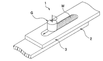
- the resin member and metal member joining method according to the present embodiment includes a superposing step of superposing the resin member 2 and the metal member 3, and friction stirring on the metal member 3. And a friction stirring step to be performed.
- the metal member 3 is placed on the resin member 2, and a part of the upper surface of the resin member 2 and a part of the lower surface of the metal member 3 are brought into contact with each other.
- the resin member 2 is a plate-like member made of PET (Polyethylene terephthalate).
- the material of the resin member 2 is not limited to PET, and may be appropriately selected from thermoplastic resins according to applications.
- the metal member 3 is a plate-like member made of aluminum alloy (A5052-O).
- the metal member 3 may be appropriately selected from metal materials capable of friction stir, such as aluminum, aluminum alloy, copper, copper alloy, titanium, titanium alloy, magnesium, and magnesium alloy, depending on the application.
- the metal member 3 is also referred to as “aluminum alloy member 3”.
- a rotary tool G (hereinafter also referred to as a friction agitation rotary tool G) is used from the upper surface side of the aluminum alloy member 3. Friction stirring is performed on the aluminum alloy member 3.
- the friction stirring tool G includes a shoulder portion G1 having a substantially columnar shape and a pin portion G2 protruding from the lower surface (end surface) of the shoulder portion G1.
- the rotary tool G for friction stirring is made of a metal material harder than the aluminum alloy member 3 such as tool steel. As shown in FIG.
- the pin portion G2 has a spiral portion G11 that exhibits a spiral shape in plan view, and a circular portion G12 that is formed in the center of the shoulder portion G1 and has a circular shape in plan view.
- a shoulder part G1 the pin part G2
- size, etc. the rotation tool for friction stirring that the lower surface (end surface) of the shoulder part G1 is flat, without providing the pin part G2.
- the resin member 2 and the aluminum alloy member 3 are restrained so as not to move, and then the lower surface (end surface) of the friction stirring rotary tool G is opposed to the aluminum alloy member 3, so The position is pushed (pressed) at a predetermined depth, and the friction stirring rotary tool G is relatively moved along the longitudinal direction of the aluminum alloy member 3.
- the rotation speed (rotation speed) and joining speed (feeding speed) of the friction stir rotating tool G are not particularly limited, for example, they are moved at a rotation speed of 1000 rpm and a joining speed of 300 mm / min.
- a plasticized region W is formed along the movement locus of the rotary tool G for friction stirring.
- the “plasticization region” includes both the state heated by the frictional heat of the friction stirring rotary tool G and actually plasticized, and the state where the friction stirring rotary tool G passes and returns to normal temperature. I will do it.
- the friction stir is performed with a pressing amount such that the plasticized region W does not contact the resin member 2.
- produced on the upper surface of the aluminum alloy member 3 by friction stirring is excised by cutting.
- the frictional heat is generated by pressing and moving the rotating tool G for friction stirring rotated from above the aluminum alloy member 3 with respect to the overlap of the resin member 2 and the aluminum alloy member 3.
- the resin on the surface (surface layer portion) of the resin member 2 is melted and cured again as the temperature decreases.
- the resin member 2 is welded and joined to the lower surface of the aluminum alloy member 3. That is, both members can be joined relatively easily by simply pressing the friction stirring rotary tool G.
- both members can be joined relatively easily by simply pressing the friction stirring rotary tool G.
- the joining method since the injection molding of the resin and the joining of the resin member and the aluminum alloy member were performed at the same time, it was impossible to join the existing member. According to the joining method, it can join also to the existing resin member 2 and the aluminum alloy member 3.
- the friction stir rotating tool G is simply pressed against the desired joint location, the degree of design freedom can be increased. Moreover, since the metal member can be pressed in a balanced manner by pressing the end surface of the rotating tool G for friction stirring against the aluminum alloy member 3, the joining accuracy can be increased. Further, the plasticized region W formed by friction stirring may be joined so as to be in contact with the resin member 2, but as shallow as the plasticized region W is not in contact with the resin member 2 as in this embodiment. Bonding can be achieved even by friction stirring.
- the outer diameter of the shoulder portion G1 of the rotary tool G for friction stirring is preferably set to 2 to 5 times the thickness of the aluminum alloy member 3. Further, it is preferable that the pressing amount of the rotary tool G for friction stirring (the pressing length from the upper surface of the aluminum alloy member 3 to the lower surface of the shoulder portion G1) is set to 5% to 20% of the thickness of the aluminum alloy member 3. .
- the said friction stirring process may be performed after forming the said contact surface in unevenness. preferable. According to such a joining method, since the molten resin enters the concave portion of the aluminum alloy member 3 and the contact area between the resin member 2 and the aluminum alloy member 3 is increased, the joining can be performed more firmly.
- Etching is performed, for example, by immersing the aluminum alloy member 3 in an etching solution prepared by adding aluminum chloride hexahydrate to a hydrochloric acid solution.
- the alumite treatment is performed by electrochemically oxidizing the surface of the aluminum alloy member 3 by electrolyzing the aluminum alloy as an anode using dilute sulfuric acid or oxalic acid.
- the surface treatment for making the surface of the aluminum alloy member 3 uneven is not limited to the etching treatment or the alumite treatment, and the surface may be roughened with a wire brush or the like to form the unevenness.
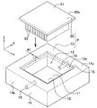
- a liquid cooling jacket P having a resin jacket body 10 and a metal (aluminum alloy in this embodiment) sealing body 30 is manufactured.
- the liquid cooling jacket P is used for cooling a heat generating body such as a CPU (Central Processing Unit), for example.
- CPU Central Processing Unit
- the liquid cooling jacket P partially includes cooling water (not shown) that is a heat transport fluid that transports heat generated by a CPU (not shown) that is a heat generator to the outside.
- a sealing body 30 that seals the opening 12 of the recess 11 is fixed to the jacket body 10 having the recess 11 that is open.
- the liquid cooling jacket P is configured such that a CPU (not shown) is attached to the center of the upper cover plate portion 31 via a heat diffusion sheet (not shown), and the CPU is attached.
- the CPU receives heat generated by the CPU and exchanges heat with the cooling water flowing through the inside.
- the cover plate part 31 transfers the heat received from the CPU to the cooling water, and as a result, the CPU is efficiently cooled.
- the heat diffusion sheet is a sheet for efficiently transferring the heat of the CPU to the cover plate portion 31, and is formed of a metal having high thermal conductivity such as copper, for example.
- the jacket main body 10 is a shallow box that is open on one side (the upper side in the present embodiment), and has a recess 11 formed therein, and has a bottom wall 13 and a peripheral wall 14. .
- the jacket body 10 is formed of a thermoplastic resin. Thereby, the liquid cooling jacket P has been reduced in weight and is easy to handle.
- a step surface 15 is formed on the opening peripheral edge portion 12 a of the recess 11 of the jacket body 10 at a position one step down from the upper surface of the peripheral wall 14.
- the distance (depth) from the upper surface of the peripheral wall 14 to the step surface 15 is equal to the thickness dimension of the cover plate portion 31 of the sealing body 30 described later.
- the width W1 of the step surface 15 is preferably set to be as small as possible in order to secure the volume of the recess 11 through which the cooling water flows. However, in the present embodiment, the width W1 is larger than the outer diameter of the shoulder portion G1 of the friction stirring tool G. Largely formed.
- Through holes 16 and 16 for allowing cooling water to flow through the recess 11 are formed in the pair of wall portions 14a and 14a facing each other of the peripheral wall 14, respectively.
- the through-holes 16 and 16 extend in the opposing direction of the walls 14a and 14a (in the X-axis direction in FIG. 3), have a circular cross section, and are formed in the intermediate portion in the depth direction of the recess 11. Is formed.
- the shape and position of the through-hole 16 are not restricted to this, It can change suitably according to the kind and flow volume of cooling water.
- the sealing body 30 is a plate-like lid having a planar shape that is the same shape (square in this embodiment) as the opening 12 (see FIG. 3) of the recess 11 of the jacket body 10. It comprises a plate portion 31 and a plurality of fins 32, 32... Provided on the lower surface of the lid plate portion 31.
- the plurality of fins 32, 32... are arranged parallel to each other and orthogonal to the lid plate portion 31, and are configured integrally with the lid plate portion 31. Thereby, heat is transmitted favorably between the cover plate portion 31 and the fins 32, 32.
- the fins 32, 32... are arranged so as to extend in a direction (X-axis direction in FIG. 3) perpendicular to the wall portions 14a, 14a of the peripheral wall 14 in which the through holes 16, 16 are formed.
- the fin 32 has a height (depth) dimension (length in the Z-axis direction in FIG. 3) equivalent to the depth dimension of the recess 11, and its tip end comes into contact with the bottom surface of the recess 11. ing.
- a cylindrical space is partitioned by the cover plate portion 31 of the sealing body 30, the adjacent fins 32 and 32, and the bottom surface of the recess 11.
- the space functions as a flow path 33 (see FIG. 5A) through which cooling water flows.
- the fins 32, 32... Have a length dimension (length in the X-axis direction in FIG. 3) that is shorter than the length dimension of one side of the recess 11, and both ends of the fins 32, 32.
- Each of the wall portions 14a, 14a is configured to be spaced from the inner wall surface by a predetermined distance.
- the sealing body 30 is formed from an aluminum alloy.
- the sealing body 30 is formed by cutting a block made of an aluminum alloy.
- the sealing body 30 may be appropriately selected from metal materials capable of friction stir, such as aluminum, aluminum alloy, copper, copper alloy, titanium, titanium alloy, magnesium, and magnesium alloy, depending on the application.
- the manufacturing method of the liquid cooling jacket according to the present embodiment includes a placing step of placing the sealing body 30 on the jacket body 10 and a friction stirring step of performing friction stirring along the inside of the abutting portion 40.
- the sealing body 30 is inserted into the recess 11 of the jacket body 10 with the fins 32 on the lower side, and the sealing body 30 is inserted.
- the lid plate portion 31 is placed on the step surface 15.
- the opening peripheral part 12a of the recessed part 11 of the jacket main body 10 and the peripheral part 30a of the sealing body 30 are faced
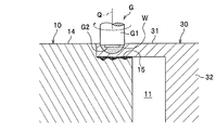
- the friction stirring rotary tool G is relatively moved along the inside of the abutting portion 40. That is, the lower surface (end surface) of the friction stirring rotary tool G is opposed to the sealing body 30 and pressed with a predetermined pressing amount, and then the step surface 15 (see FIG. 3) of the jacket body 10 and the sealing body 30 are pressed. It moves along the overlap allowance with which the cover plate part 31 overlaps. At this time, it is preferable that a jig (not shown) surrounding the jacket body 10 from four directions is applied in advance to the peripheral surface of the peripheral wall 14 of the jacket body 10 so that the jacket body 10 does not move.
- the insertion position (starting end 54 a) of the friction stirring rotary tool G is set inside the abutting portion 40. Then, with the rotation center Q of the friction stirring rotary tool G overlapped with the center of the step surface 15 in the width direction, the lid plate portion 31 is friction stirred while moving the friction stirring rotary tool G.
- the rotating tool G for friction stirring is rotated around the inside of the abutting portion 40 (see FIG. 5A) to perform friction stirring, and the sealing body 30 is fixed to the jacket body 10.
- a liquid cooling jacket P is formed.
- the resin related to the jacket main body 10 is melted by the frictional heat by the frictional stirring with respect to the aluminum alloy sealing body 30, and is cured again.
- the sealing body 30 is welded and firmly joined. That is, the jacket body 10 and the sealing body 30 can be joined simply by pressing and rotating the friction stir rotating tool G, so that the liquid cooling jacket P can be easily manufactured.
- the outer diameter of the shoulder portion G1 of the rotating tool G for friction stirring is preferably set to 2 to 5 times the thickness of the cover plate portion 31 of the sealing body 30.
- the pressing amount of the rotary tool G for friction stirring (the pressing length from the upper surface of the cover plate portion 31 to the lower surface of the shoulder portion G1) is set to 5% to 20% of the thickness of the cover plate portion 31 of the sealing body 30. It is preferable to set.
- At least the surface of the cover plate portion 31 of the sealing body 30 that is in contact with the stepped surface 15 of the jacket body 10 may be subjected to the etching process or the alumite process described above.
- the surface of the sealing body 30 made of an aluminum alloy so as to be uneven, the melted resin enters the concave portion, so that the contact area is increased and a stronger bond can be achieved.
- the jacket body 10 is provided with the step surface 15 and the sealing body 30 is placed on the step surface 15.
- the present invention is not limited to this.
- the cover plate portion 31 of the sealing body 30 is placed on the upper surface of the peripheral wall 14 of the jacket body 10, and the sealing body 30 is disposed along the overlapping margin of the peripheral wall 14 and the cover plate portion 31.
- the friction stirring step may be performed by relatively moving the friction stirring rotary tool G from above.
- the joining method according to the present embodiment includes an overlaying process in which the resin member 2 and the metal member 3 are overlapped, and a friction process in which frictional joining is performed on the overlapped members. Since the overlapping process is the same as that of the first embodiment, the description thereof is omitted.
- friction bonding is performed on the resin member 2 and the metal member 3 (aluminum alloy member 3) using a rotary tool F (hereinafter also referred to as a friction welding rotary tool F).
- the friction welding rotary tool F has a rotary shaft F1 and a tool body F2 provided at the tip of the rotary shaft F1.
- the rotation shaft F1 and the tool body F2 are formed coaxially.
- the proximal end side of the rotation shaft F1 is connected to a drive device (not shown).
- the tool main body F2 rotates at high speed around the axis when the drive of the driving device is transmitted via the rotation axis F1.
- the tool body F2 has a disk shape and is made of a metal material harder than an aluminum alloy such as tool steel.
- the shape, size, etc. of the friction welding rotary tool F may be appropriately set according to the members to be joined.
- the tool body F2 has a diameter of 100 mm and the peripheral surface F3 has a width of 4 mm.
- the thing was adopted.
- the pushing amount, the rotation speed, and the joining speed of the friction welding rotary tool F may be appropriately set according to the members to be joined.
- the pushing amount is 0.2 mm and the rotation speed is 3000 rpm.
- the joining speed was set to 500-1500 mm / min.
- the peripheral surface F3 of the tool body F2 is rotated to a predetermined depth on the upper surface of the aluminum alloy member 3 while rotating the friction welding rotary tool F. Is pushed (pressed) and moved along the overlap margin of the resin member 2 and the aluminum alloy member 3. According to the friction process, the surface of the resin member 2 is melted by the frictional heat between the friction welding rotary tool F and the aluminum alloy member 3, and when the resin member 2 is hardened again, it is welded and firmly joined to the aluminum alloy member 3.
- the joining method according to the third embodiment substantially the same effect as that of the first embodiment can be obtained. Moreover, since it can join by a small pressing force compared with 1st embodiment in a friction process, it is suitable when the member to join is thin.
- the surface of the aluminum alloy member 3 that is in contact with at least the resin member 2 is subjected to etching treatment or anodizing (anodization) treatment, and the contact surface is formed to be uneven. You may perform a process.
- the case where the plate-like resin member 2 and the aluminum alloy member 3 are joined is described as an example.
- the present invention is not limited to this.
- a friction process may be performed instead of the friction stirring process.
- Example 1 to Example 3 using the rotating tool G for friction stirring and Example 4 using the rotating tool F for friction welding were performed.
- FIG. 9 is a perspective view for explaining the first to third embodiments.
- Embodiments 1 to 3 as shown in FIG. 9, after the plate-shaped resin member 2 and the plate-shaped aluminum alloy member 3 are overlapped, the upper portion of the aluminum alloy member 3 with respect to the overlap allowance.
- the rotary tool G for friction stirring was pressed in a spot manner, and the fracture strength of the composite member 1 joined by frictional heat was measured.
- the breaking strength is measured by installing the composite member 1 shown in FIG. 9 in a known tensile testing machine, pulling the outer end of the resin member 2 and the outer end of the aluminum alloy member 3 in directions away from each other, and breaking. did.
- the resin member 2 in Examples 1 to 3 is made of PET and is formed with a length of 100 mm, a width of 30 mm, and a thickness of 3 mm.
- the aluminum alloy member 3 is formed with a length of 100 mm, a width of 30 mm, and a thickness of 3 mm or 5 mm.
- the overlap margin of the resin member 2 and the aluminum alloy member 3 is 30 mm.
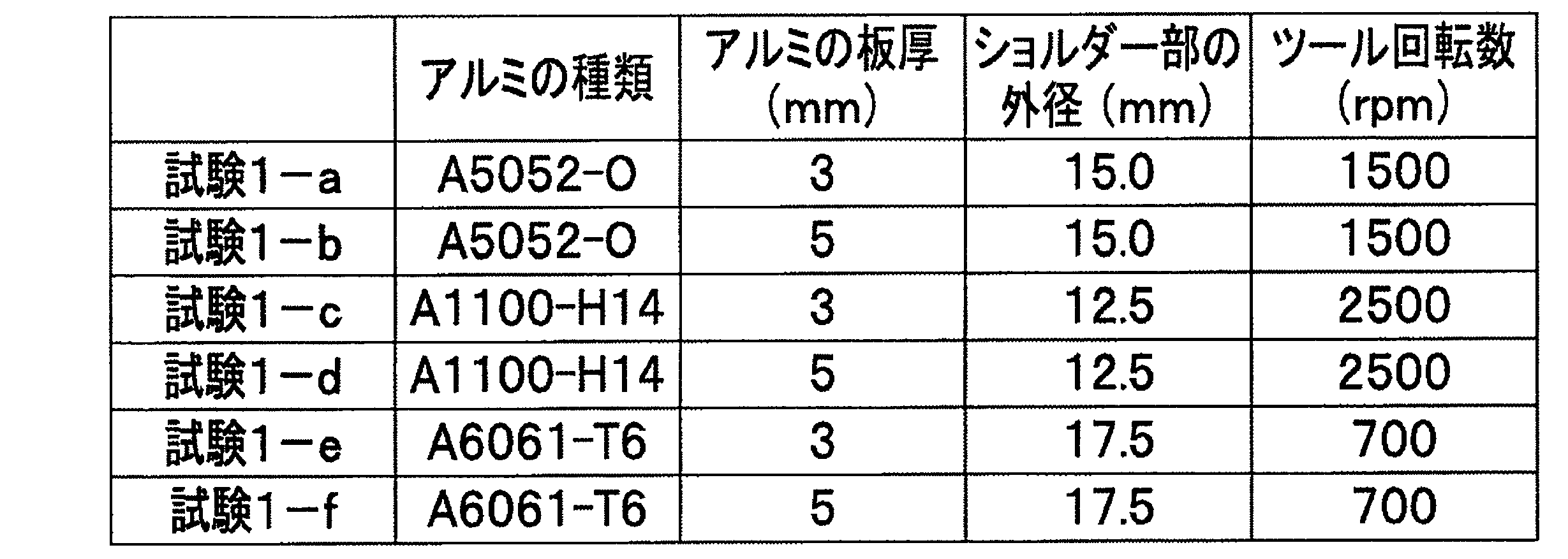
- Example 1 in order to derive the optimum indentation amount of the friction stir rotating tool G, the fracture strength (when the welding is performed with a predetermined indentation amount under the six types of conditions 1-a to 1-f) Tensile strength) was measured. Table 1 shows the conditions of each test.
- Table 2 shows the results of fracture strength at a predetermined indentation amount.
- Table 4 and Table 6 indicates that “x” is not joined, “ ⁇ ” is joined but the tensile strength is weak, and “ ⁇ ” is sufficient tensile strength. .
- the pressing amount of the friction stirring rotary tool G is set to be smaller than 5% of the thickness of the aluminum alloy member 3, the resin member 2 and the aluminum alloy member 3 can be joined. In order to obtain a sufficient tensile strength, it is desirable to set the pressing amount of the friction stirring tool G to 5% or more of the thickness of the aluminum alloy member 3.
- the pushing amount of the friction stir rotating tool G is set large, the plasticized region formed by the friction stir may come into contact with the resin member 2 and the metal and the resin may be mixed. Further, when the pressing amount of the friction stirring tool G is set large, an overload acts on the friction stirring device. Therefore, in consideration of these, it is desirable to set the pushing amount of the rotary tool G for friction stirring to 20% or less of the plate thickness of the aluminum alloy member 3.
- Example 2 in order to derive the optimum outer diameter of the shoulder portion G1 (see FIG. 2) of the rotary tool G for friction stir, a predetermined shoulder is used under the two conditions of Test 2-a to Test 2-b.
- the fracture strength (tensile strength) was measured when joining was performed with the rotating tool G for friction stirrer having the outer diameter of the part G1.
- Table 3 shows the conditions of each test.
- Table 4 shows the results of the breaking strength at the outer diameter of a predetermined shoulder portion in Test 2-a and Test 2-b.
- the fracture strength was 3000 N or more when the outer diameter of the shoulder portion was larger than ⁇ 10.0 mm, but the fracture strength was significantly lowered when the outer diameter was ⁇ 7.5 mm or less.
- the breaking strength is 3000 N or more, but when it is ⁇ 5.0 mm or less, the breaking strength is remarkably lowered. From the above, even if the outer diameter of the shoulder portion G1 of the rotating tool G for friction stirring is set to be smaller than twice the plate thickness of the aluminum alloy member 3, the resin member 2 and the aluminum alloy member 3 are joined.
- the outer diameter of the shoulder portion G1 of the rotating tool G for friction stirrer is at least twice the plate thickness of the aluminum alloy member 3. Even if the outer diameter of the shoulder portion G1 is larger than 5 times the plate thickness of the aluminum alloy member 3, the strength does not change. Therefore, considering the load on the friction stirrer, It is desirable to set it to 5 times or less the plate thickness of the aluminum alloy member 3.
- Example 3 a test was conducted on the relationship with the fracture strength when the surface of the aluminum alloy member 3 was uneven. Under the three conditions of Test 3-a to Test 3-c, the fracture strength (tensile strength) was measured when the surface of the aluminum alloy member 3 was subjected to a predetermined treatment and then joined. Table 5 shows the conditions of each test.
- Table 6 shows the results of the fracture strength in each surface treatment of the aluminum alloy member 3 in Test 3-a to Test 3-c. Of the surface treatments applied to the aluminum alloy member 3 in Table 6, “no treatment” indicates that the aluminum alloy member 3 is not subjected to surface treatment.
- etching A the following pre-etching treatment and main etching treatment are performed.
- the pre-etching treatment first, the aluminum alloy member 3 is immersed in a 30 wt% nitric acid solution at room temperature for 5 minutes, then thoroughly washed with ion-exchanged water, and then immersed in a 5 wt% sodium hydroxide solution at 50 ° C. for 1 minute. Then, it is washed with water, and further immersed in a 30 wt% nitric acid solution at room temperature for 3 minutes, and then washed with water.
- the aluminum alloy member 3 subjected to the pre-etching process is prepared in an etching solution (chlorine ion concentration: 48 g / L) prepared by adding 54 g / L of aluminum chloride hexahydrate to a 25 wt% hydrochloric acid solution.
- the sample was immersed in 66 ° C. for 4 minutes and then washed with water, further immersed in a 30 wt% nitric acid solution at room temperature for 3 minutes, washed with water, and dried with hot air at 120 ° C. for 5 minutes.
- etching B after performing the above-described pre-etching process, the following main etching process is performed. That is, in this etching main treatment, the aluminum alloy member 3 after the pre-etching treatment was immersed in a 50 wt% phosphoric acid solution at 66 ° C. for 4 minutes, washed with water, and then dried with hot air at 120 ° C. for 5 minutes. .
- the following anodized pretreatment and main anodized treatment are performed.
- the aluminum alloy member 3 is first immersed in a 30 wt% nitric acid solution at room temperature for 5 minutes, then thoroughly washed with ion-exchanged water, and then immersed in a 5 wt% sodium hydroxide solution at 50 ° C. for 1 minute. Then, it is washed with water, and further immersed in a 30 wt% nitric acid solution at room temperature for 3 minutes, and then washed with water.
- the aluminum alloy member 3 after the anodizing pretreatment is anodized in a solution having a sulfuric acid concentration of 160 g / L to a liquid temperature of 18 ° C. and a film thickness of 10 ⁇ m, and then washed with water to 120 ° C. For 5 minutes.
- the above-described anodized main treatment is performed after the aforementioned anodized pretreatment. Further, it is boiled for 10 minutes in boiling water. As a result, in “with anodized pores”, the pores are narrowed by the sealing treatment.
- the surface of the aluminum alloy member 3 was roughly cut by using a known wire brush and processed to be uneven.
- Example 4 the fracture strength of the joined members was measured in the joining method described in the third embodiment (see FIG. 8).
- the breaking strength was measured by placing the joined members on a tensile testing machine, pulling the outer end of the resin member 2 and the outer end of the aluminum alloy member 3 in directions away from each other, and breaking.
- the resin member 2 in Example 4 is made of PET and has a thickness of 5 mm.
- the aluminum alloy member 3 is an 1100 alloy and has a thickness of 1 mm or 2 mm.
- the overlap margin between the resin member 2 and the aluminum alloy member 3 is 30 mm.
- the joining length was set to 60 mm to 70 mm.
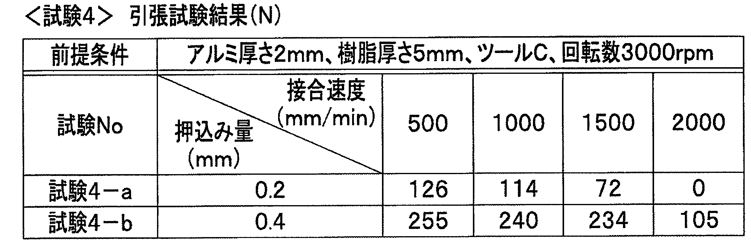
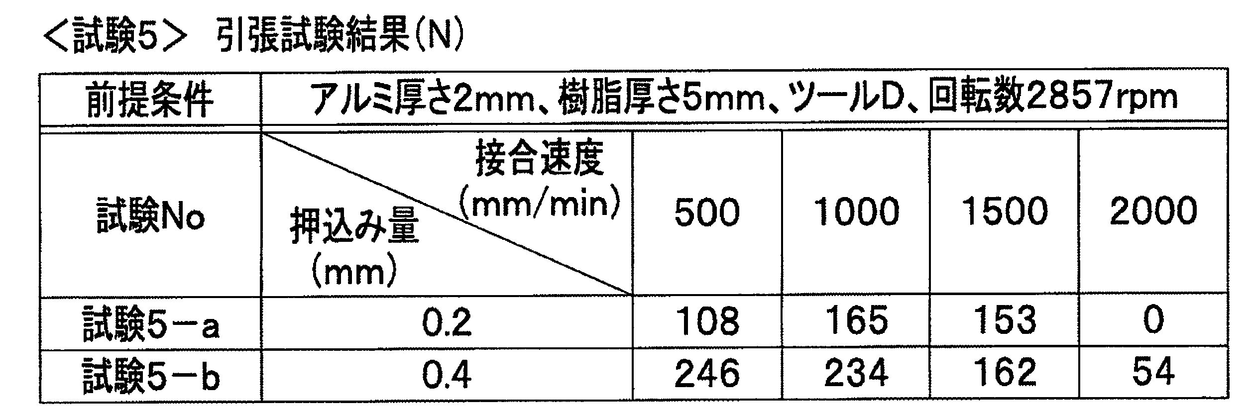
- Rotating tool F for friction welding employs two types: tool C with a tool body F2 having a diameter of 100 mm and a width of 4 mm, and tool D with a tool body F2 having a diameter of 105 mm and a width of 10 mm.
- tool C the rotation speed was set to 3000 rpm
- Tool D the rotation speed was set to 2857 rpm.
- the peripheral speed was set to 942000 (mm / min).
- Example 4 three types of preconditions (Test 4 to Test 6) were set by changing the thickness of each member and the combination of rotary tools, and a destructive test was performed using the indentation amount and the joining speed (feed speed) as parameters. It was.
- the bonding strength was low when the indentation amount was 0.2 mm, and the bonding strength was high when the indentation amount was 0.4 mm.
- the joining speed was 500 mm / min, the resin member 2 was broken. The bonding speed was sufficient up to 1500 mm / min, but the bonding strength was low at 2000 mm / min.
Landscapes
- Engineering & Computer Science (AREA)
- Mechanical Engineering (AREA)
- Theoretical Computer Science (AREA)
- Human Computer Interaction (AREA)
- Physics & Mathematics (AREA)
- General Engineering & Computer Science (AREA)
- General Physics & Mathematics (AREA)
- Pressure Welding/Diffusion-Bonding (AREA)
- Lining Or Joining Of Plastics Or The Like (AREA)
Abstract
Description
本発明の第一実施形態について、図面を参照して詳細に説明する。図1に示すように、本実施形態においては、板状の樹脂部材2と、板状の金属部材3とを接合して複合部材1を形成する場合を例にして説明する。
次に、本発明の第二実施形態について説明する。本実施形態では、図3に示すように、樹脂製のジャケット本体10と金属製(本実施形態ではアルミニウム合金製)の封止体30とを有する液冷ジャケットPを製造する場合を例にして説明する。液冷ジャケットPは、例えば、CPU(Central Processing Unit)等の熱発生体を冷却するために用いられる。
次に、本発明の第三実施形態について説明する。第一実施形態及び第二実施形態では、摩擦攪拌用回転ツールGを用いて、摩擦攪拌工程を行って樹脂部材2と金属部材3とを接合したが、第三実施形態では、回転ツールFを用いて、摩擦工程を行う点で第一実施形態及び第二実施形態と相違する。

また、試験1-c及び試験1-d、試験1-e及び試験1-fをみると、試験1-a及び試験1-bと略同様の結果になったことから、アルミニウム合金部材3の種類によっては、破壊強度には影響がないことがわかった。
一方、摩擦攪拌用回転ツールGの押込み量を大きく設定すると、摩擦攪拌により形成される塑性化領域が樹脂部材2と接触し、メタルと樹脂が混合される可能性がある。また、摩擦攪拌用回転ツールGの押込み量を大きく設定すると、摩擦攪拌装置に過負荷が作用する。したがって、これらを考慮すると、摩擦攪拌用回転ツールGの押込み量をアルミニウム合金部材3の板厚の20%以下に設定することが望ましい。

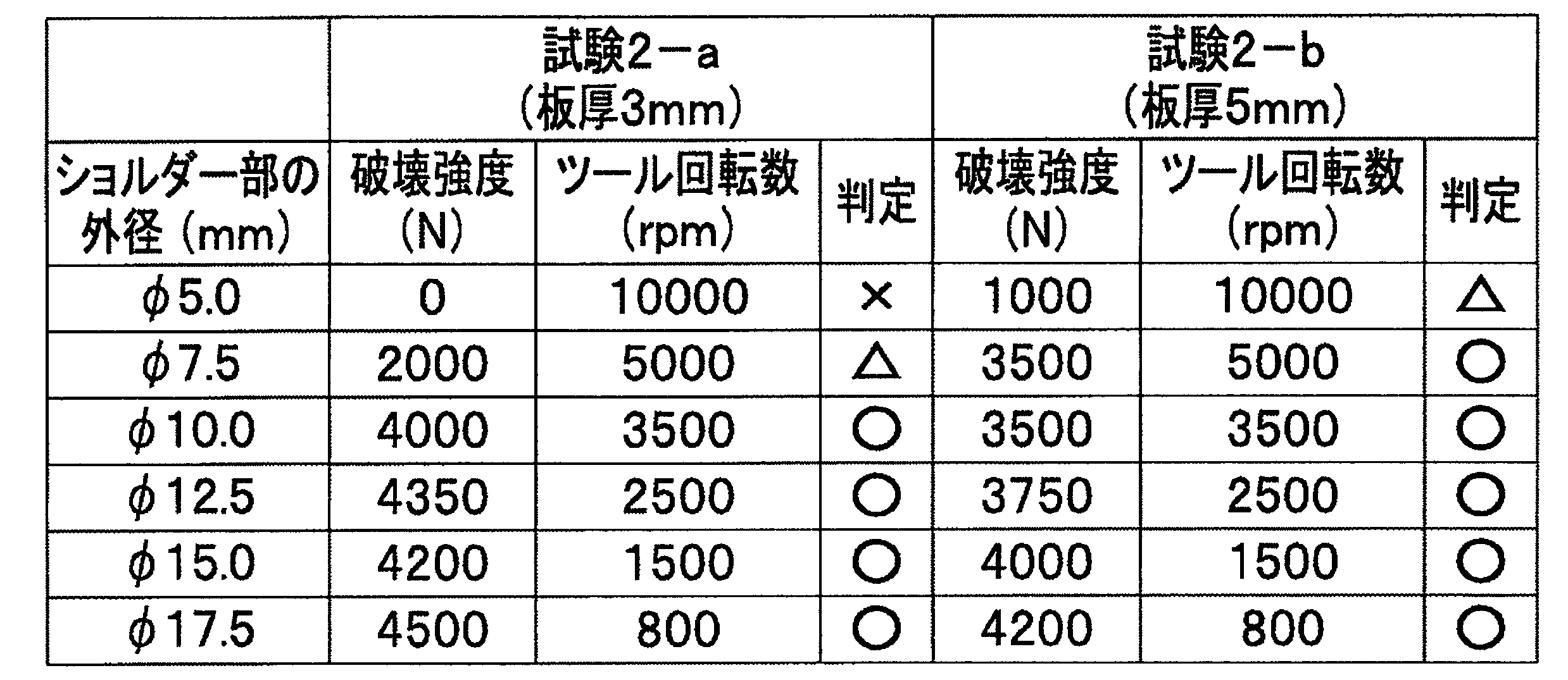
一方試験2-bにおいては、ショルダー部の外径がφ7.5mm以上であると破壊強度が3000N以上あるが、φ5.0mm以下であると破壊強度が著しく低下した。
以上より、摩擦攪拌用回転ツールGのショルダー部G1の外径をアルミニウム合金部材3の板厚の2倍よりも小さく設定したとしても、樹脂部材2とアルミニウム合金部材3とを接合するこうとは可能であるが、十分な引張強度を得るためには、摩擦攪拌用回転ツールGのショルダー部G1の外径をアルミニウム合金部材3の板厚の2倍以上にすることが望ましい。なお、ショルダー部G1の外径をアルミニウム合金部材3の板厚の5倍より大きくしても強度には変化がないため、摩擦攪拌装置への負荷を考慮すると、ショルダー部G1の外径は、アルミニウム合金部材3の板厚の5倍以下に設定することが望ましい。

表6中の、アルミニウム合金部材3に施す表面処理のうち「処理なし」は、アルミニウム合金部材3に表面処理を施していない。

また、アルミニウム合金部材3の板厚を薄くしつつ、摩擦攪拌用回転ツールGのショルダー部の外径も小さくした試験3-cの結果を見ると、「エッチングA」、「エッチングB」及び「アルマイト封孔無し」の表面処理を施した場合に高い引張強度が得られることが分かった。

2 樹脂部材
3 金属部材(アルミニウム合金部材)
10 ジャケット本体(樹脂部材)
11 凹部
12 開口部
12a 開口周縁部
14 周壁
15 段差面
30 封止体(アルミニウム合金部材)
30a 周縁部
31 蓋板部
32 フィン
F 回転ツール(摩擦接合用回転ツール)
G 回転ツール(摩擦攪拌用回転ツール)
P 液冷ジャケット
Claims (8)
- 樹脂部材と金属部材とを重ね合わせた後、回転させた回転ツールを前記金属部材側から押圧し、摩擦熱によって前記樹脂部材を溶融させて前記樹脂部材と前記金属部材とを接合することを特徴とする樹脂部材と金属部材の接合方法。
- 前記回転ツールは、摩擦攪拌用回転ツールであって、
前記摩擦攪拌用回転ツールの端面を前記金属部材に押圧することを特徴とする請求の範囲第1項に記載の樹脂部材と金属部材の接合方法。 - 前記金属部材は、アルミニウム製又はアルミニウム合金製であって、
前記摩擦攪拌用回転ツールのショルダー部の外径を、前記金属部材の厚みの2~5倍に設定することを特徴とする請求の範囲第2項に記載の樹脂部材と金属部材の接合方法。 - 前記金属部材は、アルミニウム製又はアルミニウム合金製であって、
前記摩擦攪拌用回転ツールの押込み量を、前記金属部材の厚みの5%~20%に設定することを特徴とする請求の範囲第2項又は請求の範囲第3項に記載の樹脂部材と金属部材の接合方法。 - 前記回転ツールは、摩擦接合用回転ツールであって、
摩擦接合用回転ツールの周面を前記金属部材に押圧することを特徴とする請求の範囲第1項に記載の樹脂部材と金属部材の接合方法。 - 前記金属部材は、アルミニウム製又はアルミニウム合金製であって、
接合する前に、前記金属部材にエッチング処理又は陽極酸化処理を行って表面を凸凹に形成することを特徴とする請求の範囲第1項に記載の樹脂部材と金属部材の接合方法。 - 熱発生体が発生する熱を外部に輸送する熱輸送流体が流れるとともに一部が開口した凹部を有する樹脂製のジャケット本体に、前記凹部の開口部を封止する金属製の封止体を載置した後、回転させた回転ツールを前記封止体側から押圧することにより、摩擦熱によって前記ジャケット本体の一部を溶融させて前記ジャケット本体と前記封止体とを接合することを特徴とする液冷ジャケットの製造方法。
- 前記封止体の周縁部の内側に沿って前記回転ツールを一周させて前記ジャケット本体と前記封止体とを接合することを特徴とする請求の範囲第7項に記載の液冷ジャケットの製造方法。
Priority Applications (4)
| Application Number | Priority Date | Filing Date | Title |
|---|---|---|---|
| KR1020147005588A KR101465406B1 (ko) | 2008-12-09 | 2009-12-08 | 액냉 재킷 |
| KR1020137017163A KR101471796B1 (ko) | 2008-12-09 | 2009-12-08 | 액냉 재킷 |
| KR1020117015575A KR101302349B1 (ko) | 2008-12-09 | 2009-12-08 | 수지 부재와 금속 부재의 접합 방법 및 액냉 재킷의 제조 방법 |
| CN200980150166.9A CN102239027B (zh) | 2008-12-09 | 2009-12-08 | 树脂构件与金属构件的接合方法及液冷套的制造方法 |
Applications Claiming Priority (4)
| Application Number | Priority Date | Filing Date | Title |
|---|---|---|---|
| JP2008313508 | 2008-12-09 | ||
| JP2008-313508 | 2008-12-09 | ||
| JP2009-260768 | 2009-11-16 | ||
| JP2009260768A JP5531573B2 (ja) | 2008-12-09 | 2009-11-16 | 樹脂部材と金属部材の接合方法、液冷ジャケットの製造方法及び液冷ジャケット |
Publications (1)
| Publication Number | Publication Date |
|---|---|
| WO2010067796A1 true WO2010067796A1 (ja) | 2010-06-17 |
Family
ID=42242785
Family Applications (1)
| Application Number | Title | Priority Date | Filing Date |
|---|---|---|---|
| PCT/JP2009/070541 Ceased WO2010067796A1 (ja) | 2008-12-09 | 2009-12-08 | 樹脂部材と金属部材の接合方法及び液冷ジャケットの製造方法 |
Country Status (5)
| Country | Link |
|---|---|
| JP (1) | JP5531573B2 (ja) |
| KR (3) | KR101302349B1 (ja) |
| CN (2) | CN102239027B (ja) |
| TW (2) | TWI609166B (ja) |
| WO (1) | WO2010067796A1 (ja) |
Cited By (6)
| Publication number | Priority date | Publication date | Assignee | Title |
|---|---|---|---|---|
| WO2013164294A1 (en) | 2012-04-30 | 2013-11-07 | Universite Catholique De Louvain | Method for welding at least two layers |
| WO2013185986A1 (de) * | 2012-06-14 | 2013-12-19 | Krones Ag | Verfahren zum verschliessen von kühlkanälen einer getränkeverpackungsmaschine |
| TWI492806B (zh) * | 2012-10-10 | 2015-07-21 | Nippon Light Metal Co | The method of manufacturing the heat sink and the method of manufacturing the heat transfer plate |
| US20180250767A1 (en) * | 2015-08-26 | 2018-09-06 | Nippon Light Metal Company, Ltd. | Joining method, method of manufacturing liquid cooling jacket, and liquid cooling jacket |
| CN109986191A (zh) * | 2019-04-15 | 2019-07-09 | 上海交通大学 | 一种应用于金属/高分子连接的表面处理方法 |
| DE102019107814A1 (de) * | 2019-03-27 | 2020-10-01 | Airbus Operations Gmbh | Verfahren zum Verbinden von Bauteilen, die einen faserverstärkten thermoplastischen Kunststoff aufweisen |
Families Citing this family (31)
| Publication number | Priority date | Publication date | Assignee | Title |
|---|---|---|---|---|
| EP2329905B1 (en) * | 2009-12-03 | 2012-05-30 | Helmholtz-Zentrum Geesthacht Zentrum für Material- und Küstenforschung GmbH | Method for joining metal and plastic workpieces |
| DE102010041943A1 (de) * | 2010-10-04 | 2012-04-05 | Mahle International Gmbh | Kühler |
| JP5817140B2 (ja) * | 2011-02-21 | 2015-11-18 | 昭和電工株式会社 | 金属部材と樹脂部材との接合方法 |
| CN102513691A (zh) * | 2011-12-09 | 2012-06-27 | 中国航空工业集团公司北京航空制造工程研究所 | 一种增大焊缝根部金属流动的搅拌针 |
| JP5869399B2 (ja) * | 2012-03-29 | 2016-02-24 | 京セラ株式会社 | 流路部材およびこれを用いた熱交換器ならびに半導体装置 |
| US8800847B2 (en) * | 2012-06-09 | 2014-08-12 | Apple Inc. | Dynamic path correction of friction stir welding |
| JP2014082283A (ja) * | 2012-10-15 | 2014-05-08 | T Rad Co Ltd | ヒートシンク |
| JP5838949B2 (ja) * | 2012-10-17 | 2016-01-06 | 日本軽金属株式会社 | 複合型中空容器の製造方法及び複合型中空容器 |
| JP6096016B2 (ja) * | 2013-03-18 | 2017-03-15 | 株式会社Uacj | 金属体と樹脂体との接合方法 |
| JP6102806B2 (ja) * | 2013-03-22 | 2017-03-29 | マツダ株式会社 | 異種部材の接合方法 |
| WO2015046448A1 (ja) * | 2013-09-27 | 2015-04-02 | 株式会社Uacj | 撹拌係止接合方法及び接合体 |
| JP6098526B2 (ja) * | 2014-01-14 | 2017-03-22 | マツダ株式会社 | 金属部材と樹脂部材との接合方法 |
| JP6014879B2 (ja) * | 2014-03-25 | 2016-10-26 | 株式会社栗本鐵工所 | 金属部材と樹脂部材の接合方法 |
| JP6098565B2 (ja) * | 2014-03-28 | 2017-03-22 | マツダ株式会社 | 金属部材と樹脂部材との接合方法 |
| JP6098564B2 (ja) * | 2014-03-28 | 2017-03-22 | マツダ株式会社 | 金属部材と樹脂部材との接合方法 |
| JP6098607B2 (ja) * | 2014-09-30 | 2017-03-22 | マツダ株式会社 | 金属部材と樹脂部材との接合方法 |
| JP6056828B2 (ja) * | 2014-09-30 | 2017-01-11 | マツダ株式会社 | 金属部材と樹脂部材との接合方法およびその方法において使用される樹脂部材 |
| JP6098605B2 (ja) * | 2014-09-30 | 2017-03-22 | マツダ株式会社 | 金属部材と樹脂部材との接合方法 |
| WO2017026238A1 (ja) | 2015-08-11 | 2017-02-16 | 昭和電工株式会社 | 樹脂組成物、その硬化物、及び摩擦撹拌接合方法 |
| CN105619779B (zh) * | 2016-02-25 | 2019-08-06 | 上海交通大学 | 钛合金与超高分子量聚乙烯的连接方法和接头及其应用 |
| JP6327280B2 (ja) * | 2016-03-29 | 2018-05-23 | マツダ株式会社 | 金属部材と熱硬化樹脂部材との接合方法およびその方法において使用される金属部材、熱硬化樹脂部材および熱可塑性樹脂シート |
| JP6624127B2 (ja) * | 2017-03-13 | 2019-12-25 | Jfeスチール株式会社 | 表面改質装置および表面改質方法、ならびに金属材の製造方法 |
| KR102647580B1 (ko) | 2018-10-12 | 2024-03-18 | 디아이씨 가부시끼가이샤 | 금속 수지 복합체 및 그 제조 방법 |
| WO2020075804A1 (ja) | 2018-10-12 | 2020-04-16 | Dic株式会社 | 金属樹脂複合体及びその製造方法 |
| JP7047137B2 (ja) * | 2018-12-25 | 2022-04-04 | 三井化学株式会社 | 冷却ユニット、冷却ユニットの製造方法および構造体 |
| CN109910318B (zh) * | 2019-03-20 | 2021-06-29 | 上海交通大学 | 一种使用界面原位复合相增强金属/高分子连接强度的方法 |
| CN109807460B (zh) * | 2019-03-20 | 2020-08-25 | 上海交通大学 | 一种通过检测下压力控制金属与高分子焊接的方法 |
| CN110052699B (zh) * | 2019-06-04 | 2024-03-19 | 洛阳磊佳电子科技有限公司 | 一种适用于搅拌摩擦焊焊接的中空液冷铝板封装结构 |
| CN111976149A (zh) * | 2020-07-06 | 2020-11-24 | 华南理工大学 | 一种铝合金与abs材料摩擦搭接焊方法 |
| JP2022190987A (ja) * | 2021-06-15 | 2022-12-27 | 株式会社フジクラ | コールドプレート |
| WO2023175241A1 (en) * | 2022-03-15 | 2023-09-21 | Aalto University Foundation Sr | Method for joining a metal component and a polymer component and a structure comprising said components |
Citations (8)
| Publication number | Priority date | Publication date | Assignee | Title |
|---|---|---|---|---|
| JPH07266422A (ja) * | 1994-03-30 | 1995-10-17 | Fuji Xerox Co Ltd | 超音波融着によるシート接合方法 |
| JP2003145625A (ja) * | 2001-11-09 | 2003-05-20 | Aisin Seiki Co Ltd | 熱可塑性樹脂部材の接合方法および繊維強化熱可塑性樹脂部材の接合方法 |
| JP2003329379A (ja) * | 2002-05-10 | 2003-11-19 | Furukawa Electric Co Ltd:The | ヒートパイプ回路基板 |
| JP2005534499A (ja) * | 2002-08-07 | 2005-11-17 | エクリプス アヴィエイション コーポレーション | 高分子化合物封止剤を伴った摩擦攪拌溶接等による表面同士の溶接方法ならびに溶接構造物 |
| JP2007098439A (ja) * | 2005-10-05 | 2007-04-19 | Sumitomo Light Metal Ind Ltd | 段付き重合せ材料の摩擦撹拌接合製品 |
| JP2008162280A (ja) * | 2006-12-29 | 2008-07-17 | General Electric Co <Ge> | 繊維強化熱可塑性樹脂摩擦攪拌接合 |
| JP2008221321A (ja) * | 2007-03-15 | 2008-09-25 | Mazda Motor Corp | 摩擦点接合方法 |
| JP2009279858A (ja) * | 2008-05-23 | 2009-12-03 | Sumitomo Light Metal Ind Ltd | 金属材と樹脂材の接合方法、及び金属材と樹脂材の接合体 |
Family Cites Families (17)
| Publication number | Priority date | Publication date | Assignee | Title |
|---|---|---|---|---|
| JPH10230376A (ja) * | 1997-02-21 | 1998-09-02 | Showa Alum Corp | 金属製板状接合体 |
| US6045028A (en) * | 1998-07-17 | 2000-04-04 | Mcdonnell Douglas Corporation | Integral corrosion protection of friction-welded joints |
| JP3429475B2 (ja) * | 2000-05-08 | 2003-07-22 | 川崎重工業株式会社 | スポット接合装置およびスポット接合方法 |
| JP3482523B2 (ja) * | 2000-10-24 | 2003-12-22 | 川崎重工業株式会社 | 摩擦接合方法 |
| CN100436028C (zh) * | 2002-08-29 | 2008-11-26 | 日本轻金属株式会社 | 元件接合方法、金属元件接合方法、散热元件与其制造方法、以及散热器 |
| JP2005122503A (ja) * | 2003-10-17 | 2005-05-12 | Hitachi Ltd | 冷却装置およびこれを内蔵した電子機器 |
| JP4227886B2 (ja) * | 2003-11-27 | 2009-02-18 | 三菱重工業株式会社 | 摩擦攪拌接合用の金属板材の表面処理方法、表面処理金属板材、及び摩擦攪拌接合方法 |
| JP2006179771A (ja) * | 2004-12-24 | 2006-07-06 | Mitsubishi Electric Corp | 電気デバイス及び冷却ジャケット |
| KR20070113271A (ko) * | 2005-03-04 | 2007-11-28 | 니폰게이긴조쿠가부시키가이샤 | 금속 2층 구조체 및 그 제조 방법 및 이 방법을 이용한스퍼터링 타깃의 재생 방법 |
| JP4305406B2 (ja) * | 2005-03-18 | 2009-07-29 | 三菱電機株式会社 | 冷却構造体 |
| JP4855707B2 (ja) * | 2005-04-20 | 2012-01-18 | 住友軽金属工業株式会社 | 燃料電池用アルミニウム板及びそれを用いたセパレータ並びにエンドプレート及びそれらを用いた燃料電池。 |
| US20090065178A1 (en) * | 2005-04-21 | 2009-03-12 | Nippon Light Metal Company, Ltd. | Liquid cooling jacket |
| JP4452220B2 (ja) * | 2005-08-19 | 2010-04-21 | 東ソー株式会社 | 複合体およびその製造方法 |
| US7497917B2 (en) * | 2005-08-31 | 2009-03-03 | Gm Global Technology Operations, Inc. | Friction heating for joining dissimilar materials |
| JP2007266418A (ja) * | 2006-03-29 | 2007-10-11 | Sanyo Electric Co Ltd | 半導体装置およびその製造方法 |
| JP2008055445A (ja) * | 2006-08-30 | 2008-03-13 | Hitachi Ltd | 構造体の製作方法及び構造体 |
| JP5120605B2 (ja) * | 2007-05-22 | 2013-01-16 | アイシン・エィ・ダブリュ株式会社 | 半導体モジュール及びインバータ装置 |
-
2009
- 2009-11-16 JP JP2009260768A patent/JP5531573B2/ja active Active
- 2009-12-08 CN CN200980150166.9A patent/CN102239027B/zh active Active
- 2009-12-08 WO PCT/JP2009/070541 patent/WO2010067796A1/ja not_active Ceased
- 2009-12-08 KR KR1020117015575A patent/KR101302349B1/ko active Active
- 2009-12-08 CN CN201410507777.7A patent/CN104308357B/zh active Active
- 2009-12-08 KR KR1020137017163A patent/KR101471796B1/ko active Active
- 2009-12-08 KR KR1020147005588A patent/KR101465406B1/ko active Active
- 2009-12-09 TW TW103121322A patent/TWI609166B/zh active
- 2009-12-09 TW TW098142033A patent/TWI552856B/zh active
Patent Citations (8)
| Publication number | Priority date | Publication date | Assignee | Title |
|---|---|---|---|---|
| JPH07266422A (ja) * | 1994-03-30 | 1995-10-17 | Fuji Xerox Co Ltd | 超音波融着によるシート接合方法 |
| JP2003145625A (ja) * | 2001-11-09 | 2003-05-20 | Aisin Seiki Co Ltd | 熱可塑性樹脂部材の接合方法および繊維強化熱可塑性樹脂部材の接合方法 |
| JP2003329379A (ja) * | 2002-05-10 | 2003-11-19 | Furukawa Electric Co Ltd:The | ヒートパイプ回路基板 |
| JP2005534499A (ja) * | 2002-08-07 | 2005-11-17 | エクリプス アヴィエイション コーポレーション | 高分子化合物封止剤を伴った摩擦攪拌溶接等による表面同士の溶接方法ならびに溶接構造物 |
| JP2007098439A (ja) * | 2005-10-05 | 2007-04-19 | Sumitomo Light Metal Ind Ltd | 段付き重合せ材料の摩擦撹拌接合製品 |
| JP2008162280A (ja) * | 2006-12-29 | 2008-07-17 | General Electric Co <Ge> | 繊維強化熱可塑性樹脂摩擦攪拌接合 |
| JP2008221321A (ja) * | 2007-03-15 | 2008-09-25 | Mazda Motor Corp | 摩擦点接合方法 |
| JP2009279858A (ja) * | 2008-05-23 | 2009-12-03 | Sumitomo Light Metal Ind Ltd | 金属材と樹脂材の接合方法、及び金属材と樹脂材の接合体 |
Cited By (8)
| Publication number | Priority date | Publication date | Assignee | Title |
|---|---|---|---|---|
| WO2013164294A1 (en) | 2012-04-30 | 2013-11-07 | Universite Catholique De Louvain | Method for welding at least two layers |
| WO2013185986A1 (de) * | 2012-06-14 | 2013-12-19 | Krones Ag | Verfahren zum verschliessen von kühlkanälen einer getränkeverpackungsmaschine |
| TWI492806B (zh) * | 2012-10-10 | 2015-07-21 | Nippon Light Metal Co | The method of manufacturing the heat sink and the method of manufacturing the heat transfer plate |
| US20180250767A1 (en) * | 2015-08-26 | 2018-09-06 | Nippon Light Metal Company, Ltd. | Joining method, method of manufacturing liquid cooling jacket, and liquid cooling jacket |
| US10668559B2 (en) * | 2015-08-26 | 2020-06-02 | Nippon Light Metal Company, Ltd. | Joining method, method of manufacturing liquid cooling jacket, and liquid cooling jacket |
| DE102019107814A1 (de) * | 2019-03-27 | 2020-10-01 | Airbus Operations Gmbh | Verfahren zum Verbinden von Bauteilen, die einen faserverstärkten thermoplastischen Kunststoff aufweisen |
| US11173670B2 (en) | 2019-03-27 | 2021-11-16 | Airbus Operations Gmbh | Method for connecting components which have a fibre-reinforced thermoplastic plastic |
| CN109986191A (zh) * | 2019-04-15 | 2019-07-09 | 上海交通大学 | 一种应用于金属/高分子连接的表面处理方法 |
Also Published As
| Publication number | Publication date |
|---|---|
| KR20140034326A (ko) | 2014-03-19 |
| TW201029826A (en) | 2010-08-16 |
| TWI552856B (zh) | 2016-10-11 |
| CN102239027B (zh) | 2014-12-03 |
| KR101302349B1 (ko) | 2013-08-30 |
| CN104308357B (zh) | 2016-06-29 |
| TWI609166B (zh) | 2017-12-21 |
| CN102239027A (zh) | 2011-11-09 |
| TW201437601A (zh) | 2014-10-01 |
| KR101471796B1 (ko) | 2014-12-10 |
| KR20130085060A (ko) | 2013-07-26 |
| JP5531573B2 (ja) | 2014-06-25 |
| CN104308357A (zh) | 2015-01-28 |
| JP2010158885A (ja) | 2010-07-22 |
| KR20110102412A (ko) | 2011-09-16 |
| KR101465406B1 (ko) | 2014-11-25 |
Similar Documents
| Publication | Publication Date | Title |
|---|---|---|
| JP5531573B2 (ja) | 樹脂部材と金属部材の接合方法、液冷ジャケットの製造方法及び液冷ジャケット | |
| JP5949835B2 (ja) | 液冷ジャケット | |
| JP5262822B2 (ja) | 液冷ジャケットの製造方法 | |
| JP6036714B2 (ja) | 液冷ジャケットの製造方法 | |
| CN107000114B (zh) | 液冷套筒的制造方法及液冷套筒 | |
| JP6489219B2 (ja) | 接合方法、液冷ジャケットの製造方法及び液冷ジャケット | |
| JP4962423B2 (ja) | 伝熱板の製造方法 | |
| JP5573973B2 (ja) | 液冷ジャケットの製造方法 | |
| CN107921576A (zh) | 液冷套筒的制造方法及液冷套筒 | |
| CN111405960A (zh) | 液冷套的制造方法 | |
| JP6885262B2 (ja) | 液冷ジャケットの製造方法 | |
| JP6769427B2 (ja) | 液冷ジャケットの製造方法 | |
| JP5062155B2 (ja) | 液冷ジャケットの製造方法および摩擦攪拌接合方法 | |
| WO2013094246A1 (ja) | 液冷ジャケットの製造方法 | |
| JP5136072B2 (ja) | 液冷ジャケットの製造方法 | |
| JP2014240706A (ja) | 伝熱板、及びその製造方法 | |
| JP6950580B2 (ja) | 液冷ジャケットの製造方法 | |
| JP2021186858A (ja) | 液冷ジャケットの製造方法 | |
| KR20080057965A (ko) | 용접 툴 및 이 툴을 이용한 마찰 교반 점 용접 방법 |
Legal Events
| Date | Code | Title | Description |
|---|---|---|---|
| WWE | Wipo information: entry into national phase |
Ref document number: 200980150166.9 Country of ref document: CN |
|
| 121 | Ep: the epo has been informed by wipo that ep was designated in this application |
Ref document number: 09831900 Country of ref document: EP Kind code of ref document: A1 |
|
| NENP | Non-entry into the national phase |
Ref country code: DE |
|
| ENP | Entry into the national phase |
Ref document number: 20117015575 Country of ref document: KR Kind code of ref document: A |
|
| 122 | Ep: pct application non-entry in european phase |
Ref document number: 09831900 Country of ref document: EP Kind code of ref document: A1 |