WO2010067553A1 - 円柱状ボンド磁石およびその製造方法並びに棒状磁石体 - Google Patents
円柱状ボンド磁石およびその製造方法並びに棒状磁石体 Download PDFInfo
- Publication number
- WO2010067553A1 WO2010067553A1 PCT/JP2009/006605 JP2009006605W WO2010067553A1 WO 2010067553 A1 WO2010067553 A1 WO 2010067553A1 JP 2009006605 W JP2009006605 W JP 2009006605W WO 2010067553 A1 WO2010067553 A1 WO 2010067553A1
- Authority
- WO
- WIPO (PCT)
- Prior art keywords
- bonded magnet
- cylindrical bonded
- magnet
- cylindrical
- magnetic
- Prior art date
- Legal status (The legal status is an assumption and is not a legal conclusion. Google has not performed a legal analysis and makes no representation as to the accuracy of the status listed.)
- Ceased
Links
Images





Classifications
-
- H—ELECTRICITY
- H01—ELECTRIC ELEMENTS
- H01F—MAGNETS; INDUCTANCES; TRANSFORMERS; SELECTION OF MATERIALS FOR THEIR MAGNETIC PROPERTIES
- H01F41/00—Apparatus or processes specially adapted for manufacturing or assembling magnets, inductances or transformers; Apparatus or processes specially adapted for manufacturing materials characterised by their magnetic properties
- H01F41/02—Apparatus or processes specially adapted for manufacturing or assembling magnets, inductances or transformers; Apparatus or processes specially adapted for manufacturing materials characterised by their magnetic properties for manufacturing cores, coils, or magnets
- H01F41/0253—Apparatus or processes specially adapted for manufacturing or assembling magnets, inductances or transformers; Apparatus or processes specially adapted for manufacturing materials characterised by their magnetic properties for manufacturing cores, coils, or magnets for manufacturing permanent magnets
- H01F41/0266—Moulding; Pressing
-
- H—ELECTRICITY
- H01—ELECTRIC ELEMENTS
- H01F—MAGNETS; INDUCTANCES; TRANSFORMERS; SELECTION OF MATERIALS FOR THEIR MAGNETIC PROPERTIES
- H01F41/00—Apparatus or processes specially adapted for manufacturing or assembling magnets, inductances or transformers; Apparatus or processes specially adapted for manufacturing materials characterised by their magnetic properties
- H01F41/02—Apparatus or processes specially adapted for manufacturing or assembling magnets, inductances or transformers; Apparatus or processes specially adapted for manufacturing materials characterised by their magnetic properties for manufacturing cores, coils, or magnets
- H01F41/0253—Apparatus or processes specially adapted for manufacturing or assembling magnets, inductances or transformers; Apparatus or processes specially adapted for manufacturing materials characterised by their magnetic properties for manufacturing cores, coils, or magnets for manufacturing permanent magnets
- H01F41/0273—Imparting anisotropy
-
- H—ELECTRICITY
- H01—ELECTRIC ELEMENTS
- H01F—MAGNETS; INDUCTANCES; TRANSFORMERS; SELECTION OF MATERIALS FOR THEIR MAGNETIC PROPERTIES
- H01F7/00—Magnets
- H01F7/02—Permanent magnets [PM]
- H01F7/0205—Magnetic circuits with PM in general
-
- H—ELECTRICITY
- H01—ELECTRIC ELEMENTS
- H01F—MAGNETS; INDUCTANCES; TRANSFORMERS; SELECTION OF MATERIALS FOR THEIR MAGNETIC PROPERTIES
- H01F13/00—Apparatus or processes for magnetising or demagnetising
- H01F13/003—Methods and devices for magnetising permanent magnets
-
- H—ELECTRICITY
- H02—GENERATION; CONVERSION OR DISTRIBUTION OF ELECTRIC POWER
- H02K—DYNAMO-ELECTRIC MACHINES
- H02K15/00—Processes or apparatus specially adapted for manufacturing, assembling, maintaining or repairing of dynamo-electric machines
- H02K15/02—Processes or apparatus specially adapted for manufacturing, assembling, maintaining or repairing of dynamo-electric machines of stator or rotor bodies
- H02K15/03—Processes or apparatus specially adapted for manufacturing, assembling, maintaining or repairing of dynamo-electric machines of stator or rotor bodies having permanent magnets
Definitions
- the present invention relates to a cylindrical bonded magnet in which N poles and S poles are alternately multipolarly magnetized in the axial direction.
- Cylindrical magnets in which a plurality of permanent magnets are arranged such that the same kind of magnetic poles face each other are used in various fields.
- a foreign matter removing device for removing iron powder and the like from food and a stator for a linear motor
- Patent Document 1 Patent Document 2, Patent Document 3 and the like.
- the N poles are opposed to each other, so the lines of magnetic force extending from each N pole extend in the direction orthogonal to the axial direction of the cylindrical magnet Draw a large arc to the south pole.
- the magnetic field can be effectively formed outside the cylindrical magnet. Therefore, in the case of a foreign matter removing device, the ability to collect foreign matter can be increased, and in the case of a linear motor, it is possible to obtain a strong propulsive force.
- Patent Document 1 After a plurality of magnets are fitted in the container, the magnets are fixed by welding the container and the sealing members provided at both ends of the container. Further, in Patent Document 2, each of the plurality of magnets is fixed by an adhesive and sealed in a container made of a nonmagnetic material.
- Patent Document 2 when assembling a magnet, it is necessary to make the same kind of magnetic poles face each other, and it is dangerous because of receiving a large repulsive force, and the workability is bad, and until the adhesive solidifies, with a jig It is necessary to fix the magnet, and there is a problem that productivity is low.
- the stator in which the cylindrical magnet is inserted into the support shaft described in Patent Document 3 is fixed by the groove portion provided on the support shaft and the convex portion provided on the cylindrical magnet.
- the present invention has been made in view of such circumstances, and an object thereof is to provide a cylindrical bonded magnet which is excellent in productivity and has a desired magnetic pole pattern without degrading magnetic characteristics.
- the present invention is a cylindrical bonded magnet made of a magnetic powder and a resin, wherein the cylindrical bonded magnet is a single molded body, and N poles and S poles are alternately multipolarly magnetized in the axial direction. It is a cylindrical bonded magnet characterized by the above.
- the axial direction is a direction parallel to the axis of the cylinder.
- the surface magnetic flux is measured along the axial direction of the side surface of the cylindrical bonded magnet.
- a cylindrical bonded magnet characterized in that the surface magnetic flux density distribution forms a substantially sinusoidal waveform having nodes at both ends.
- the present invention is a rod-like magnet body provided with a cylindrical bond magnet and a nonmagnetic pipe accommodating at least two or more of the cylindrical bond magnets, and the surface magnetic flux is generated along the axial direction of the side surface of the nonmagnetic pipe.
- the surface magnetic flux density distribution is characterized in that it forms a continuous substantially sinusoidal waveform.
- the said cylindrical bonded magnet is shape
- the magnetic powder is preferably an anisotropic rare earth-iron-nitrogen based alloy powder.
- the present invention also includes a step of kneading a magnetic powder and a resin to obtain a compound, and a step of forming the compound into a columnar bond magnet while applying an orientation magnetic field, in the method of producing a columnar bond magnet,
- the magnetic field is formed by an orientation magnet in which a plurality of magnets are joined such that the same kind of magnetic poles face each other, and the orientation magnet is disposed so as to surround the cylindrical bonded magnet. It is a manufacturing method of a pillar-shaped bond magnet.
- the cylindrical bonded magnet in which the north pole and the south pole are multipolarly magnetized in the axial direction of the present invention is a single molded body, and therefore has excellent productivity.
- FIG. 7 shows an enlarged view of the ends of the cylindrical bonded magnet shown in FIG. 6; The state which connected two or more cylindrical bond magnets shown by FIG. 6 is shown.
- the distribution of the magnetic flux density in the axial direction (C-C ') in the side surface of several cylindrical bonded magnets shown in FIG. 10 is shown.
- each element constituting the present invention may be configured such that a plurality of elements are constituted by the same member and one member is used in common as a plurality of elements, or conversely, the function of one member is realized by a plurality of members It can be shared and realized.
- FIG. 1 is a schematic front view of a cylindrical bonded magnet according to the present embodiment.
- the cylindrical bonded magnet of the present embodiment is manufactured by an injection molding machine described later, but it is manufactured in one molding process (filling of compound to cavity portion ⁇ solidification of resin in compound ⁇ cylindrical bonded magnet which is a molded body) ). Therefore, the cylindrical bonded magnet of the present invention is a single molded body. Therefore, unlike the prior art, there is no need to assemble the repelling magnet pieces one by one.
- the cylindrical bonded magnet of the present invention is different from a magnet obtained by bonding a plurality of magnet pieces with an adhesive or the like, or a cylindrical magnet obtained by bending end faces of a sheet magnet and bonding them together.
- the cylindrical bonded magnet of the present invention does not have an adhesive surface or a bonding surface inside.
- the cylindrical bonded magnet of this embodiment is a single molded body, the magnetic force can be efficiently extracted from the side surface of the cylindrical magnet as in the conventional case where the same kind of magnetic poles are opposed to each other to assemble the magnet. Therefore, it can be suitably used for an apparatus such as a foreign matter removing apparatus or a linear motor which requires a magnetic force from the side surface of the magnet.
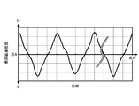
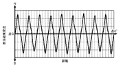
- FIG. 2 is a characteristic diagram showing the distribution of magnetic flux density in the axial direction (A-A ') of the side surface of the cylindrical bonded magnet shown in FIG.
- the cylindrical bonded magnet of the present invention is multipolarly magnetized in the axial direction, its distribution is sinusoidal when the magnetic flux density is measured along (A-A ').
- the distribution map of the magnetic flux density in the axial direction on any side surface is almost the same as FIG. This means that the cylindrical bonded magnet of the present invention is multipolarly magnetized on all sides.
- the distribution and strength of such magnetic flux density of the cylindrical bonded magnet of the present invention is due to the arrangement of orientation magnets used at the time of injection molding described later.
- FIG. 3 is a cross-sectional view showing the inside of the injection molding machine.
- the cylindrical bonded magnet of the present invention is produced by an injection molding machine, but filling of the molten compound in the cavity, solidification of the resin in the compound, and cylindrical molded magnet which is a molded product in one molding process. Takes out. Inside the injection molding machine, a cavity 1 serving as a mold of a molded body, an orientation magnet 3 provided so as to surround the cavity 1, a cavity 3 and an orientation magnet 3 to separate the orientation magnets 3 And an ejector pin 4 for pushing out the solidified molded body.
- the orientation magnet 3 has a role of orienting the magnetic powder contained in the molten compound filled in the cavity 1.
- orientation magnet 3 is disposed so as to surround the cavity portion 1, all the side surfaces of the obtained cylindrical bonded magnet are multipolarly magnetized as described above. Furthermore, since the orientation magnet 3 is disposed up to the end of the molded body formed inside the cavity portion 1, the strength (peak top) of the surface magnetic flux density in any magnetic pole of the cylindrical bonded magnet is It will be almost the same.
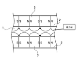
- FIG. 4 is a schematic cross-sectional view for explaining magnetic lines of force generated inside the cavity 1 by the orientation magnet 3.
- the magnetic powder in the compound filled inside the cavity portion 1 is oriented upon receiving magnetic lines of force as shown in FIG. Then, from the surface of the cylindrical bonded magnet taken out, magnetic lines of force shown in FIG. 1 are generated.
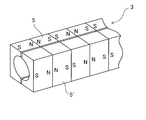
- FIG. 5 is a schematic perspective view showing the entire image of the orientation magnet 3.
- the orientation magnet 3 is composed of a plurality of U-shaped and axially oriented magnets of the same size, and is divided into a pair of joined bodies 5 and 5 'in which the magnets are adhesively fixed so that the same kind of magnetic poles face each other. .
- the respective junctions 5, 5 ′ are accommodated in the side wall 2 and installed so as to surround the cavity portion 1.
- the orientation magnet 3 so as to surround the cavity portion 1, it is possible to multipolarize all the side surfaces of the cylindrical bonded magnet.
- the alignment magnet 3 is composed of a plurality of magnets, in the present invention, it is possible to produce a cylindrical bonded magnet having four or more magnetic poles. Then, the width of each of the magnets used for the orientation magnet 3 determines the orientation pitch of the manufactured cylindrical bonded magnet.
- the orientation pitch of the cylindrical bonded magnet of the present invention is preferably 1 mm or more and 30 mm or less from the viewpoint of practicality and easiness of manufacture.
- the orientation pitch is the distance between the maximum position of the surface magnetic flux density of the N pole and the maximum position of the surface magnetic flux density of the adjacent S pole. That is, the orientation pitch is the distance between the magnetic poles. If the orientation pitch is smaller than 1 mm, the thickness of the permanent magnet for orientation installed inside the mold needs to be thinner than 1 mm accordingly, which makes it very difficult to process and assemble in the mold, so it is practical Not In addition, the magnetic force in each magnetic pole also becomes weak.
- the orientation pitch is larger than 30 mm, the place where the strong magnetic force is generated decreases, so the foreign matter adsorption efficiency is reduced. Also, in the case of a linear motor, the occurrence of the distance between the magnetic poles adversely affects the precision of operation.
- the production method can also be relatively easily produced by an assembly method, so the orientation pitch is 30 mm or less when it is desired to take advantage of the integral molding feature of the present invention. Is preferred.
- the manufacturing time is shorter than the method by assembly, and it can be easily manufactured.
- FIG. 8 is a cross-sectional view showing the inside of a mold for molding a cylindrical bonded magnet according to the second invention.
- the difference between the inside of the molding machine and the first invention of the second invention is, as shown in FIGS. 3 and 8, the positional relationship between the cavity portion and the permanent magnet for orientation.
- (XX ') in FIG. 3 and (YY') in FIG. 8 indicate the position of the end face of the cavity portion.
- the orientation permanent magnet in the mold used in the second invention as shown by (YY ') in FIG. 8, the positional relationship between the molded article cavity and the orientation permanent magnet is the same as (X-- in FIG. As compared with X '), the alignment permanent magnets are offset by half. That is, in the mold used in the second invention, the end face of the cavity portion is disposed between the N pole and the S pole of the orientation permanent magnet.
- FIG. 6 is a schematic front view of a cylindrical bonded magnet molded using the mold of FIG.
- FIG. 7 is a characteristic diagram showing the distribution of the magnetic flux density in the axial direction (B-B ') on the side surface of the cylindrical bonded magnet shown in FIG.
- the surface magnetic flux density distribution of the side surface of the obtained cylindrical bonded magnet is a sine wave, and both the start point B and the end point B 'are nodes.
- the number of magnetic poles of the cylindrical bonded magnet may be odd or even, but in the second invention, the number of magnetic poles is even.
- FIG. 9 (a) and 9 (b) show enlarged views of both end portions of the cylindrical bonded magnet shown in FIG.
- the surface magnetic flux density is approximately zero.
- the inside of the end face on the point P side is partially the S pole.
- the surface magnetic flux density is almost zero at point Q in FIG.
- the inside of the end face on the Q side is partially an N pole.
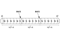
- FIG. 10 is a front view schematically showing a rod-like magnet body connected using three pieces of the cylindrical bonded magnet shown in FIG. 6 using magnetic force.
- FIG. 11 shows the distribution of the surface magnetic flux density when the surface magnetic flux density is measured along the point C-C 'on the side surface of the rod-like magnet body shown in FIG.
- the bar-like magnet body shown in FIG. 10 has a location connected using the magnetic force of a plurality of cylindrical bonded magnets, the entire surface magnetic flux density of the bar-like magnet body The distribution is obtained as a continuous sinusoidal waveform.
- the material of the magnet used for the orientation magnet 3 preferably has a residual magnetic flux density Br of 1 T or more.
- a NdFeB sintered magnet can be used.
- the cylindrical bonded magnet obtained by injection molding as described above has a function as a magnet because the magnetization easy axis of the magnetic powder in the bonded magnet is aligned by the orientation magnet 3, but after molding, If necessary, a magnetization process may be performed. By magnetizing, the magnetic force of the cylindrical bonded magnet can be made stronger.
- anisotropic or isotropic magnetic powder can be applied.
- anisotropic magnetic powder ferrite type, SmCo5 type, Nd-Fe-B type, Sm-Fe-N type, etc. may be mentioned.
- isotropic magnetic powders include Sm-Co-based and Nd-Fe-B-based.
- the anisotropic magnetic powder is very easy to align the magnetization directions due to the magnetic field applied during orientation, and as a result, the magnetic force of the cylindrical bonded magnet becomes strong.
- the above magnetic powders can be used singly or in combination of two or more. Moreover, you may perform an oxidation resistance process and a coupling process as needed.
- the resin used in the first or second invention is not particularly limited, and examples thereof include thermoplastic resins such as polypropylene, polyethylene, polyvinyl chloride, polyester, polyamide, polycarbonate, polyphenylene sulfide and acrylic resin, and ester resins, Thermoplastic elastomers such as polyamides can be used. Moreover, it is also possible to mix and use these suitably.
- the mixing ratio of the magnetic powder to the resin depends on the kind of the resin, it is desirable that the ratio of the magnetic powder to the whole of the cylindrical bonded magnet is 45 to 65 vol%.
- antioxidants, lubricants and the like can be further mixed.
- molding method for example, extrusion molding, compression molding, or injection molding can be applied. From the viewpoint of productivity and easiness of installation of alignment equipment, molding by injection molding is particularly preferred.
- a cylindrical one having an inner diameter of 5 mm and a total length of 70 mm is used.
- the magnets are adhered to each other so that the same kind of magnetic poles face each other, and the orientation magnet shown in FIG. 5 is manufactured.
- an orientation magnet is placed so as to surround the cavity. That is, permanent magnets for orientation are disposed such that the same kind of magnetic poles of a plurality of small magnets having a U-shaped cross section face each other.
- the permanent magnets for orientation are disposed facing each other in a U-shape so as to form a cavity.
- the injection molding machine sets the cylinder temperature for melting the compound to 230 ° C., and sets the temperature in the cavity to 90 ° C.
- the molten compound is filled into the cavity while applying the orienting magnetic field from the orienting magnet.
- the injection pressure of the injection molding machine is set to 100 MPa, and the injection speed is set to 80 mm / s.
- the resin in the compound begins to solidify as it is filled into the cavity and forms a molded body. After holding the molded body in the cavity for 8 seconds, the cavity is opened. Next, the molded body is pushed out by the ejector pin, and a cylindrical bonded magnet with a diameter of 5 mm, a total length of 70 mm, and an orientation pitch of 5 mm is obtained.
- Example 2 (Preparation of compound) The same compound as in Example 1 was used.
- the cavity portion of the injection molding machine in the present embodiment has a cylindrical shape with an inner diameter of 5 mm and a total length of 30 mm.
- the magnets are adhered to each other so that the same kind of magnetic poles face each other, and the orientation magnet shown in FIG. 5 is manufactured.
- a cavity part is formed and the magnet for orientation is installed.
- the end face of the cavity portion is adjusted to be intermediate between the N pole and the S pole of the orientation magnet.
- the injection molding machine sets the cylinder temperature for melting the compound to 230 ° C. and sets the temperature of the cavity portion to 90 ° C.
- the molten compound is filled into the cavity while applying the orienting magnetic field from the orienting magnet.
- the injection pressure of the injection molding machine is set to 100 MPa, and the injection speed is set to 80 mm / s.
- the resin in the compound begins to solidify as it is filled into the cavity and forms a molded body. After holding the molded body in the cavity for 8 seconds, the cavity is opened. Next, the molded body is pushed out by the ejector pin, and a cylindrical bonded magnet having a diameter of 5 mm, a total length of 30 mm, an orientation pitch of 5 mm, and six magnetic poles is obtained.
- Comparative Example 1 (Production of bond magnet piece) Using the compound produced in Example 1, a cylindrical bonded magnet piece having a diameter of 5 mm and a height of 5 mm is produced by an injection molding machine. The cylindrical bonded magnet pieces are axially oriented. The cavity shape and the orientation magnet should be changed as appropriate. The conditions at the time of molding are the same as in Example 1 except that a 9 kOe oriented magnetic field is applied in the thickness direction of the cylindrical bonded magnet piece.
- FIG. 12 is a schematic perspective view showing a cylindrical bonded magnet manufactured in Comparative Example 2.
- the cylindrical bonded magnet comprises a cylindrical bonded magnet piece 6 having a cavity at its center, a support shaft 7 inserted into the hollow of the cylindrical bonded magnet piece 6, and a fastener 8 for fixing the cylindrical bonded magnet piece 6.
- a convex portion is formed in a part of the hollow portion of the cylindrical bonded magnet piece 6, and the cylindrical bonded magnet piece 6 and the supporting shaft are made by fitting the convex portion in a groove formed in the supporting shaft 7. 7 can be fixed. That is, the cylindrical bonded magnet pieces 6 can be arranged in parallel without using an adhesive or the like.
- a groove is formed in the circumferential direction according to the shape of the fastener 8, and the tubular bond magnet piece 6 is completely fixed by fitting the fastener 8 into the groove It can be done.
- the supporting shaft 7 is made of SUS304 and has an outer diameter of 2.4 mm and a total length of 75 mm.
- the convex portion of the cylindrical bonded magnet piece 6 is moved along the groove of the support shaft 7, and the cylindrical bonded magnet pieces 6 are fixed to the support shaft 7 one by one.
- Fourteen cylindrical bonded magnet pieces 6 are arranged so that the same kind of magnetic poles face each other, and finally fixed with fasteners 8.
- Comparative Example 3 (Preparation of cylindrical bonded magnet pieces) The cylindrical bonded magnet piece used in Comparative Example 1 is used as the cylindrical bonded magnet piece.
- Table 1 shows the number of moldings required to produce ten cylindrical bonded magnets or rod-like magnets and the time required for injection molding them. The time taken for injection molding is the time from the formation of the first molded body to the formation of the required number of final molded bodies.
- Example 2 and Comparative Examples 1 to 3 the times required for assembling ten cylindrical bonded magnets or rod-like magnet bodies are shown in Table 1.
- Example 1 does not require assembly time.
- Example 2 took 3 minutes to assemble 10 pieces, but no repulsive force is exerted between the magnet pieces at the time of inserting the pipe, so the assembling time is quicker in several steps compared with the comparative example. .
- Table 1 shows the yields when 100 cylindrical bonded magnets or rod-like magnet bodies are produced.
- Example 1 since one cylindrical bonded magnet can be manufactured in one molding process, the time required for injection molding is small. On the other hand, in Comparative Examples 1 to 3, since it is necessary to manufacture a large amount of cylindrical bonded magnet pieces, the time required for injection molding is increased. And, in Comparative Examples 1 to 3, time for assembling into a cylindrical bonded magnet or a rod-like magnet body is further required. Although Comparative Example 2 is not shown in Table 1, it takes time to process the cylindrical bonded magnet piece into a cylindrical shape and time to manufacture the support shaft and the fastener. From these facts, it is understood that the cylindrical bonded magnet of the present invention is excellent in productivity.
- Comparative Example 1 and Comparative Example 3 the yield is lowered due to adhesion failure and welding failure, but in the present invention, since it is not necessary to perform such operation, a cylindrical bonded magnet having high quality is produced with high productivity. It can be provided safely.
- Example 1 and Example 2 are comparable in comparison with Comparative Example 1 and Comparative Example 3 to obtain a comparable property.
- Comparative Example 2 since the cylindrical magnet piece is used, the characteristics deteriorate.
- the surface magnetic flux density distribution can be obtained as a continuous sinusoidal waveform.
- the cylindrical bonded magnet of the present invention can be used as a permanent magnet material for a foreign matter removing device or a linear motor.
Landscapes
- Engineering & Computer Science (AREA)
- Power Engineering (AREA)
- Manufacturing & Machinery (AREA)
- Physics & Mathematics (AREA)
- Electromagnetism (AREA)
- Manufacturing Cores, Coils, And Magnets (AREA)
- Powder Metallurgy (AREA)
- Hard Magnetic Materials (AREA)
Abstract
【課題】生産性に優れ、軸方向に多極磁化された円柱状ボンド磁石を提供する。 【解決手段】磁性粉末と樹脂からなる円柱状ボンド磁石であって、円柱状ボンド磁石は、単一の成形体であり、軸方向にN極とS極が交互に多極磁化されている。さらに円柱状ボンド磁石、少なくとも4極以上の偶数極に交互に多極磁化されていると共に、円柱状ボンド磁石の側面の軸方向に沿って表面磁束を測定したときに、その表面磁束密度分布が、両端を節とした略正弦波形を示す。
Description
本発明は、軸方向にN極とS極が交互に多極磁化された円柱状ボンド磁石に関する。
同種の磁極が対向するように複数の永久磁石を配置させた円柱状磁石は、様々な分野で使用されている。例えば、食品から鉄粉等を除去するための異物除去装置やリニアモータ用の固定子に用いられる(特許文献1、特許文献2、特許文献3等)。このような円柱状磁石は例えばN極の場合、N極同士は対向しているため、各N極から伸びる磁力線は、円柱状磁石の軸方向に対して直交する方向に伸び、N極と隣接するS極へと大きな弧を描く。結果的に、円柱状磁石の外部に効果的に磁場を形成することができる。そのため、異物除去装置の場合には、異物の捕集能力を高くすることができ、リニアモータの場合には、強い推進力を得ることが可能となる。
特許文献1では、容器内に複数の磁石を嵌め込んだ後に、容器の両端に設けられた封止部材と容器とを溶接することにより磁石が固定される。また、特許文献2では、複数の磁石は、それぞれが接着剤により固定されて、非磁性材料からなる容器に封入される。これらの方法は、磁石を組み立てる際、同種の磁極同士を対向させなければならず、大きな反発力を受けるため危険で、作業性が悪く、また、接着剤が固化するまでの間、治具で磁石を固定する必要があり、生産性が低いという問題があった。
これに対して、特許文献3に記載される支持軸に筒状磁石が嵌め込まれた固定子は、支持軸に設けられた溝部と筒状磁石に設けられた凸部により固定されるため、接着剤を使用する必要もなく、安全に組み立て作業を行うことができる。しかし、組み立て作業自体は、手作業で行う必要があるため、依然として、生産性が低いという問題がある。また、円筒状磁石の中央部には、空洞が生じるため、磁力が低下するという問題もあった。
本発明は、斯かる事情に鑑みてなされたものであり、磁気特性を低下させることなく、生産性に優れ、所望の磁極パターンを有する円柱状ボンド磁石を提供することにある。
上記の問題点を解決すべく、本発明者らは鋭意検討を重ねた結果、本発明を完成するに到った。
本発明は、磁性粉末と樹脂からなる円柱状ボンド磁石であって、上記円柱状ボンド磁石は、単一の成形体であり、軸方向にN極とS極が交互に多極磁化されていることを特徴とする円柱状ボンド磁石である。ここで、軸方向とは、円柱の軸に対して平行な方向とする。
本発明は、上記の円柱状ボンド磁石が、少なくとも4極以上の偶数極に交互に多極磁化されていると共に、該円柱状ボンド磁石の側面の軸方向に沿って表面磁束を測定したときに、その表面磁束密度分布が、両端を節とした略正弦波形を形成することを特徴とする円柱状ボンド磁石である。
本発明は、円柱状ボンド磁石と、その円柱状ボンド磁石を少なくとも2個以上収納する非磁性パイプとを備えた棒状磁石体であり、上記非磁性パイプの側面の軸方向に沿って表面磁束を測定したときに、その表面磁束密度分布が、連続した略正弦波形を形成することを特徴とする。
また、上記円柱状ボンド磁石は、射出成形によって成形されることが好ましい。
さらに、上記磁性粉末は、異方性の希土類-鉄-窒素系合金粉末であることが好ましい。
また、本発明は、円柱状ボンド磁石の製造方法において、磁性粉末と樹脂を混練しコンパウンドを得る工程と配向磁場を印加しながら上記コンパウンドを円柱状ボンド磁石に成形する工程を有し、上記配向磁場は、同種の磁極が対向するように複数の磁石を接合させた配向用磁石により形成され、上記配向用磁石は、上記円柱状ボンド磁石を囲むように設置されていることを特徴とする円柱状ボンド磁石の製造方法である。
本発明の軸方向にN極とS極が多極磁化された円柱状ボンド磁石は、単一の成形体であるため、優れた生産性を有する。
本発明を実施するための最良の形態を、以下に図面を参照しながら説明する。ただし、以下に示す形態は、本発明の技術思想を具体化するための円柱状ボンド磁石およびその製造方法を例示するものであって、本発明は、円柱状ボンド磁石およびその製造方法を以下に限定するものではない。
また、本明細書は特許請求の範囲に示される部材を、実施の形態の部材に特定するものでは決してない。実施の形態に記載されている構成部品の寸法、材質、形状、その相対的配置等は、特に特定的な記載がない限りは、本発明の範囲をそれのみに限定する趣旨ではなく、単なる説明例にすぎない。なお、各図面が示す部材の大きさや位置関係等は、説明を明確にするため誇張していることがある。さらに以下の説明において、同一の名称、符号については同一もしくは同質の部材を示しており、詳細な説明を適宜省略する。さらに、本発明を構成する各要素は、複数の要素を同一の部材で構成して一の部材で複数の要素を兼用する態様としてもよいし、逆に一の部材の機能を複数の部材で分担して実現することもできる。
[実施の形態1]
以下、第1の発明に係る実施の形態について詳述するが、本発明の技術思想を具体化するための一例であり、本発明は、この実施の形態及び実施例に限定するものではない。
以下、第1の発明に係る実施の形態について詳述するが、本発明の技術思想を具体化するための一例であり、本発明は、この実施の形態及び実施例に限定するものではない。
図1は、本形態に係る円柱状ボンド磁石の模式的な正面図である。本形態の円柱状ボンド磁石は、後述する射出成形機によって作製されるが、一回の成形工程(キャビティ部へのコンパウンドの充填→コンパウンド中の樹脂の固化→成形体である円柱状ボンド磁石の取り出し)によって作製される。そのため、本発明の円柱状ボンド磁石は、単一の成形体となる。したがって、従来のように反発する磁石ピース同士をひとつずつ組み立てる作業を必要としない。本発明の円柱状ボンド磁石は、複数の磁石ピースを接着剤等によって貼り合わせた磁石体や一枚のシート磁石の端面同士を折り曲げて貼り合わせた筒状磁石とは異なるものであり、本発明の円柱状ボンド磁石は、その内部に接着面や接合面を有するものではない。また、本形態の円柱状ボンド磁石は、単一の成形体であるが、同種の磁極同士を対向させて磁石を組み立てる従来の場合と同様に、円柱状磁石の側面から効率的に磁力を取り出せることができるので、磁石側面からの磁力を必要とする異物除去装置やリニアモータなどの装置に好適に使用することができる。
図2は、図1に示す円柱状ボンド磁石側面の軸方向(A-A’)における磁束密度の分布を示す特性図である。実際には、実施例で作製した円柱状ボンド磁石を用いて測定を行った。本発明の円柱状ボンド磁石は軸方向に多極磁化されているため、(A-A’)に沿って磁束密度を測定すると、その分布は正弦曲線となる。一例として、(A-A’)における磁束密度の分布を示したが、いずれの側面における軸方向の磁束密度の分布図も、図2とほぼ同一となる。これは、本発明の円柱状ボンド磁石は全側面において多極磁化されていることを意味する。本発明の円柱状ボンド磁石のこのような磁束密度の分布や強さは、後述する射出成形時に使用する配向用磁石の配置によるものである。
図3は、射出成形機内部を示す断面図である。本発明の円柱状ボンド磁石は、射出成形機によって作製されるが、一回の成形工程で、溶融状コンパウンドのキャビティ部への充填、コンパウンド中の樹脂の固化、成形体である円柱状ボンド磁石の取り出しが行われる。
射出成形機の内部には、成形体の型枠となるキャビティ部1と、キャビティ部1を囲むように設けられた配向用磁石3と、キャビティ部1と配向用磁石3を隔て配向用磁石3を収容する側壁2と、固化された成形体を押し出すためのエジェクターピン4が設けられている。配向用磁石3は、キャビティ部1内部に充填された溶融状のコンパウンドに含まれる磁性粉末を配向させる役割を有す。また、配向用磁石3は、キャビティ部1を囲んで配置されているため、上述のように、得られる円柱状ボンド磁石の全側面は多極磁化されている。さらに、配向用磁石3は、キャビティ部1内部に形成される成形体の末端部にまで配置されているため、円柱状ボンド磁石のいずれの磁極における表面磁束密度の強さ(ピークトップ)は、ほぼ同じとなる。
射出成形機の内部には、成形体の型枠となるキャビティ部1と、キャビティ部1を囲むように設けられた配向用磁石3と、キャビティ部1と配向用磁石3を隔て配向用磁石3を収容する側壁2と、固化された成形体を押し出すためのエジェクターピン4が設けられている。配向用磁石3は、キャビティ部1内部に充填された溶融状のコンパウンドに含まれる磁性粉末を配向させる役割を有す。また、配向用磁石3は、キャビティ部1を囲んで配置されているため、上述のように、得られる円柱状ボンド磁石の全側面は多極磁化されている。さらに、配向用磁石3は、キャビティ部1内部に形成される成形体の末端部にまで配置されているため、円柱状ボンド磁石のいずれの磁極における表面磁束密度の強さ(ピークトップ)は、ほぼ同じとなる。
図4は、配向用磁石3によってキャビティ部1内部で発生する磁力線を説明するための概略断面図である。キャビティ部1内部に充填されたコンパウンド中の磁性粉末は、図4に示すような磁力線を受けて配向する。そして、取り出された円柱状ボンド磁石の表面からは、図1に示す磁力線を発生する。
図5は、配向用磁石3の全体像を示す概略斜視図である。配向用磁石3は、コ字状でアキシャル配向させた同じサイズの複数の磁石からなり、同種の磁極が対向するように磁石同士が接着固定された一対の接合体5、5’に分かれている。それぞれの接合体5、5’は、側壁2内に収容され、キャビティ部1を取り囲むように設置される。キャビティ部1を囲むように配向用磁石3を配置させることで、円柱状ボンド磁石の全側面を多極磁化させることができる。また、配向用磁石3は、複数の磁石からなるため、本発明では、4極以上の磁極数を有する円柱状ボンド磁石を作製することが可能である。そして、配向用磁石3に用いられる個々の磁石の幅によって、作製される円柱状ボンド磁石の配向ピッチが決まる。
本発明の円柱状ボンド磁石の配向ピッチは、実用性や製造の容易性の面から、1mm以上30mm以下であることが好ましい。配向ピッチとは、N極の表面磁束密度の最大位置と、それと隣り合うS極の表面磁束密度の最大位置との距離とする。すなわち、配向ピッチとは、磁極間距離のことである。配向ピッチが1mmより小さいと、それに合わせて金型内部に設置する配向用の永久磁石の厚みも1mmより薄くする必要があり、加工および金型内部への組み付けが非常に困難になるため現実的でない。また各磁極における磁力も弱くなる。また、配向ピッチが30mmより大きい場合、強い磁力を発生させる箇所が減少するため、異物の吸着効率を低下させる。また、リニアモータの場合、磁極間に距離が生じることにより、動作の精密さに悪影響を与える。さらに本発明でも作製は容易にできるが、組み立てによる方法でも比較的容易に作製することができるため、本発明の特徴とする一体成形の利点を生かしたい場合は、配向ピッチは、30mm以下であることが好ましい。また、本発明は、3極以上の円柱状ボンド磁石とするときに、組み立てによる方法よりも作製時間が短縮され、容易に作製することができる。
[実施の形態2]
次に、第二の発明に係る実施の形態について説明する。図8は、第二の発明に係る円柱状ボンド磁石を成形するための金型の内部を示す断面図である。成形機の内部について第二の発明の第一の発明との相違する点は、図3および図8に示されるように、キャビティ部と配向用永久磁石の位置関係である。図3中における(X-X’)および図8における(Y-Y’)は、キャビティ部の端面の位置を示す。第二の発明で用いる金型内の配向用永久磁石は、図8の(Y-Y’)に示されるように、成形品キャビティと配向用永久磁石の位置関係が、図3の(X-X’)と比較して、配向用永久磁石半個分ずれたものとなっている。すなわち、第二の発明で用いる金型では、配向用永久磁石のN極とS極の中間にキャビティ部の端面が配置される。
次に、第二の発明に係る実施の形態について説明する。図8は、第二の発明に係る円柱状ボンド磁石を成形するための金型の内部を示す断面図である。成形機の内部について第二の発明の第一の発明との相違する点は、図3および図8に示されるように、キャビティ部と配向用永久磁石の位置関係である。図3中における(X-X’)および図8における(Y-Y’)は、キャビティ部の端面の位置を示す。第二の発明で用いる金型内の配向用永久磁石は、図8の(Y-Y’)に示されるように、成形品キャビティと配向用永久磁石の位置関係が、図3の(X-X’)と比較して、配向用永久磁石半個分ずれたものとなっている。すなわち、第二の発明で用いる金型では、配向用永久磁石のN極とS極の中間にキャビティ部の端面が配置される。
図6は、図8の金型を用いて成形した円柱状ボンド磁石の概略正面図である。さらに、図7は、図6に示された円柱状ボンド磁石の側面における軸方向(B-B’)の磁束密度の分布を示す特性図である。第二の発明は、図7に示されるように、得られる円柱状のボンド磁石の側面の表面磁束密度分布が、正弦波となり、しかも始点Bと終点B’が共に節となっている。
また、第一の発明では、円柱状ボンド磁石の磁極数は、奇数個でも偶数個でも良いが、第二の発明では、磁極数は偶数個である。
図9(a)および図9(b)は、図6で示した円柱状ボンド磁石の両端部分の拡大図を示す。図9(a)中の点Pでは、表面磁束密度は、ほぼ0である。なお、点P側の端面の内部は、部分的にS極になっている。一方、第二の発明の円柱状ボンド磁石は、その側面に偶数極が形成されているので、反対側である図9(b)では、点Qで表面磁束密度はほぼ0であり、しかも点Q側の端面の内部は、部分的にN極になっている。
このように、円柱状ボンド磁石の端面において、側面端部は表面磁束密度が、共にほぼ0であるが、両端面の内部は、それぞれ部分的に、S極とN極が形成されているので、図6に示される円柱状ボンド磁石を1ピースとして、複数ピースの異極の端面を近づけると、それらの端面は、異極であるので互いに磁力が作用して、容易に繋げることができる。図10は、図6に示される円柱状ボンド磁石を3ピース利用して、磁力を利用して繋げた棒状磁石体を模式的に示す正面図である。
図11は、図10に示される棒状磁石体の側面における点C‐C’間に沿って、表面磁束密度を測定したときの表面磁束密度の分布を示す。図11に示されるように、図10に示される棒状磁石体は、複数の円柱状ボンド磁石の磁力を利用して繋げた箇所を有するにも関わらず、その棒状磁石体の全体の表面磁束密度分布は、連続した正弦波形のものが得られる。
第1または第2の発明において、配向用磁石3に使用する磁石の材料は、残留磁束密度Brが1T以上のものが好ましく、例えば、NdFeB焼結磁石を用いることができる。磁力の大きい磁石を使うと、キャビティ部の内部に発生する磁力が強くなり、円柱状ボンド磁石の磁力も強くなる。
また、上述のように射出成形で得られた円柱状ボンド磁石は、配向用磁石3によって、ボンド磁石中の磁性粉末の磁化容易軸が揃えられるため、磁石としての機能を有するが、成形後、必要であれば、着磁工程を行ってもよい。着磁を行うことで、円柱状ボンド磁石の磁力をより強力なものとすることができる。
第1または第2の発明で用いられる磁性粉末は、異方性又は等方性の磁性粉末が適用可能である。例えば、異方性磁性粉末としては、フェライト系、SmCo5系、Nd-Fe-B系、Sm-Fe-N系などが挙げられる。等方性磁性粉末としては、Sm-Co系、Nd-Fe-B系などが挙げられる。磁力の強い円柱状ボンド磁石を作製する必要がある場合には、異方性磁性粉末を用いることが好ましく、特に、Sm-Fe-N系が好ましい。これは、異方性磁性粉末は、配向の際に印加される磁場によって、磁化方向が非常に揃いやすく、結果的に円柱状ボンド磁石の磁力が強くなるためである。上記の磁性粉末は一種類単独でも二種以上を混合物としても使用可能である。また必要に応じて耐酸化処理やカップリング処理を施しても良い。
第1または第2の発明で用いられる樹脂としては、特に制限はなく、例えば、ポリプロピレン、ポリエチレン、ポリ塩化ビニル、ポリエステル、ポリアミド、ポリカーボネート、ポリフェニレンサルファイド、アクリル樹脂などの熱可塑性樹脂や、エステル系、ポリアミド系などの熱可塑性エラストマーを使用することができる。また、これらを適宜混合して使用することも可能である。
磁性粉末と樹脂の配合比率は、樹脂の種類にもよるが、円柱状ボンド磁石全体に対する磁性粉末の割合が45~65vol%とすることが望ましい。また、酸化防止剤、滑剤等をさらに混合することもできる。
なお、成形方法としては、特に限定されるものではなく、例えば、押出成形、圧縮成形または射出成形を適用することができる。生産性、配向設備の設置の容易性から、特に射出成形によって成形することが好ましい。
以下、本発明の実施例について説明するが、本発明はこれに限定されるものではない。
1.円柱状ボンド磁石の作製
<実施例1>
(磁性粉末の準備)
磁性粉末には、異方性のSm-Fe-N系磁性粉末(平均粒子径3μm)を用いる。
<実施例1>
(磁性粉末の準備)
磁性粉末には、異方性のSm-Fe-N系磁性粉末(平均粒子径3μm)を用いる。
(コンパウンドの作製)
上記のSm-Fe-N系磁性粉末をエチルシリケートおよびシランカップリング剤で表面処理する。表面処理を行ったSm-Fe-N系磁性粉末9137gと12ナイロン863gをミキサーで混合する。得られた混合粉を、2軸混練機を用いて220℃で混練し、冷却後適当な大きさに切断しコンパウンドを得る。
上記のSm-Fe-N系磁性粉末をエチルシリケートおよびシランカップリング剤で表面処理する。表面処理を行ったSm-Fe-N系磁性粉末9137gと12ナイロン863gをミキサーで混合する。得られた混合粉を、2軸混練機を用いて220℃で混練し、冷却後適当な大きさに切断しコンパウンドを得る。
(円柱状ボンド磁石の作製)
射出成形機のキャビティ部には、内径5mm、全長70mmの円柱状のものを使用する。配向用磁石には、市販のNdFeB焼結磁石(Br=1.35T)を使用し、個々の磁石の幅は、5mmである。同種の磁極が対向するように磁石同士を接着させ、図5に示す配向用磁石を作製する。そして、図3に示すように、キャビティ部を囲むように配向用磁石を設置する。すなわち、配向用の永久磁石は、断面コの字型の複数の小磁石の同種の磁極が対向するように配置している。さらに、配向用の永久磁石は、キャビティ部を形成するように、コの字形状を向かい合わせに配置されている。射出成形機は、コンパウンドを溶融させるシリンダー温度を230℃とし、キャビティ部内の温度を90℃に設定する。配向用磁石からの配向磁場を印加させた状態で、溶融させたコンパウンドをキャビティ部へ充填させる。射出成形機の射出圧を100MPaとし、射出速度を80mm/sに設定する。コンパウンド中の樹脂は、キャビティ部へ充填されると同時に固化し始め、成形体を形成する。キャビティ部内に成形体を8秒間保持させた後、キャビティを開放させる。次に、エジェクターピンにより成形体が押し出され、直径5mm、全長70mm、配向ピッチ5mmの円柱状ボンド磁石が得られる。
射出成形機のキャビティ部には、内径5mm、全長70mmの円柱状のものを使用する。配向用磁石には、市販のNdFeB焼結磁石(Br=1.35T)を使用し、個々の磁石の幅は、5mmである。同種の磁極が対向するように磁石同士を接着させ、図5に示す配向用磁石を作製する。そして、図3に示すように、キャビティ部を囲むように配向用磁石を設置する。すなわち、配向用の永久磁石は、断面コの字型の複数の小磁石の同種の磁極が対向するように配置している。さらに、配向用の永久磁石は、キャビティ部を形成するように、コの字形状を向かい合わせに配置されている。射出成形機は、コンパウンドを溶融させるシリンダー温度を230℃とし、キャビティ部内の温度を90℃に設定する。配向用磁石からの配向磁場を印加させた状態で、溶融させたコンパウンドをキャビティ部へ充填させる。射出成形機の射出圧を100MPaとし、射出速度を80mm/sに設定する。コンパウンド中の樹脂は、キャビティ部へ充填されると同時に固化し始め、成形体を形成する。キャビティ部内に成形体を8秒間保持させた後、キャビティを開放させる。次に、エジェクターピンにより成形体が押し出され、直径5mm、全長70mm、配向ピッチ5mmの円柱状ボンド磁石が得られる。
<実施例2>
(コンパウンドの作製)
実施例1と同じコンパウンドを使用した。
(コンパウンドの作製)
実施例1と同じコンパウンドを使用した。
(円柱状ボンド磁石の作製)
本実施例における射出成形機のキャビティ部は、内径5mm、全長30mmの円柱状とする。配向用磁石には、市販のNdFeB焼結磁石(残留磁束密度Br=1.35T)を使用し、個々の磁石の幅は、5mmである。同種の磁極が対向するように磁石同士を接着させ、図5に示す配向用磁石を作製する。そして、図8に示すように、キャビティ部を形成して配向用磁石を設置する。ここで、配向用磁石のN極とS極の中間にキャビティ部の端面がくるように調整される。射出成形機は、コンパウンドを溶融させるシリンダー温度を230℃とし、キャビティ部の温度を90℃に設定する。配向用磁石からの配向磁場を印加させた状態で、溶融させたコンパウンドをキャビティ部へ充填させる。射出成形機の射出圧を100MPaとし、射出速度を80mm/sに設定する。コンパウンド中の樹脂は、キャビティ部へ充填されると同時に固化し始め、成形体を形成する。キャビティ部内に成形体を8秒間保持させた後、キャビティ部を開放させる。次に、エジェクターピンにより成形体が押し出され、直径5mm、全長30mm、配向ピッチ5mm、磁極数が6極の円柱状ボンド磁石が得られる。
本実施例における射出成形機のキャビティ部は、内径5mm、全長30mmの円柱状とする。配向用磁石には、市販のNdFeB焼結磁石(残留磁束密度Br=1.35T)を使用し、個々の磁石の幅は、5mmである。同種の磁極が対向するように磁石同士を接着させ、図5に示す配向用磁石を作製する。そして、図8に示すように、キャビティ部を形成して配向用磁石を設置する。ここで、配向用磁石のN極とS極の中間にキャビティ部の端面がくるように調整される。射出成形機は、コンパウンドを溶融させるシリンダー温度を230℃とし、キャビティ部の温度を90℃に設定する。配向用磁石からの配向磁場を印加させた状態で、溶融させたコンパウンドをキャビティ部へ充填させる。射出成形機の射出圧を100MPaとし、射出速度を80mm/sに設定する。コンパウンド中の樹脂は、キャビティ部へ充填されると同時に固化し始め、成形体を形成する。キャビティ部内に成形体を8秒間保持させた後、キャビティ部を開放させる。次に、エジェクターピンにより成形体が押し出され、直径5mm、全長30mm、配向ピッチ5mm、磁極数が6極の円柱状ボンド磁石が得られる。
<比較例1>
(ボンド磁石ピースの作製)
実施例1で作製したコンパウンドを用いて、射出成形機にて、直径5mm、高さ5mmの円柱状ボンド磁石ピースを作製する。円柱状ボンド磁石ピースはアキシャル配向させる。キャビィティの形状や配向用磁石については、適宜変更する。成形時の条件は、円柱状ボンド磁石ピースの厚み方向に9kOe配向磁場を印加する以外は、実施例1と同様である。
(ボンド磁石ピースの作製)
実施例1で作製したコンパウンドを用いて、射出成形機にて、直径5mm、高さ5mmの円柱状ボンド磁石ピースを作製する。円柱状ボンド磁石ピースはアキシャル配向させる。キャビィティの形状や配向用磁石については、適宜変更する。成形時の条件は、円柱状ボンド磁石ピースの厚み方向に9kOe配向磁場を印加する以外は、実施例1と同様である。
(円柱状ボンド磁石の作製)
14個の円柱状ボンド磁石ピースを同種の磁極が対向するように、一つずつ、接着剤で固定する。接着剤が固化するまでの間、治具で磁石を固定する。接着剤には、市販のエポキシ系接着剤(ハンツマン・アドバンスト・マテリアルズ社製、商品名:アラルダイトラピッド)を使用する。
14個の円柱状ボンド磁石ピースを同種の磁極が対向するように、一つずつ、接着剤で固定する。接着剤が固化するまでの間、治具で磁石を固定する。接着剤には、市販のエポキシ系接着剤(ハンツマン・アドバンスト・マテリアルズ社製、商品名:アラルダイトラピッド)を使用する。
<比較例2>
図12は、比較例2で作製する円柱状ボンド磁石を示す概略斜視図である。円柱状ボンド磁石は、中央に空洞を有する筒状ボンド磁石ピース6と筒状ボンド磁石ピース6の空洞に挿入される支持軸7と筒状ボンド磁石ピース6を固定する留め具8からなる。筒状ボンド磁石ピース6の空洞の一部には、凸部が形成されており、支持軸7に形成された溝にその凸部を嵌合させることにより、筒状ボンド磁石ピース6と支持軸7とを固定させることができる。つまり、接着剤等を用いることなく、筒状ボンド磁石ピース6同士を並列させることができる。また、支持軸7の末端には、留め具8の形状に合わせて周方向に溝が形成されており、その溝に留め具8を嵌め込むことにより、筒状ボンド磁石ピース6を完全に固定させることができる。
図12は、比較例2で作製する円柱状ボンド磁石を示す概略斜視図である。円柱状ボンド磁石は、中央に空洞を有する筒状ボンド磁石ピース6と筒状ボンド磁石ピース6の空洞に挿入される支持軸7と筒状ボンド磁石ピース6を固定する留め具8からなる。筒状ボンド磁石ピース6の空洞の一部には、凸部が形成されており、支持軸7に形成された溝にその凸部を嵌合させることにより、筒状ボンド磁石ピース6と支持軸7とを固定させることができる。つまり、接着剤等を用いることなく、筒状ボンド磁石ピース6同士を並列させることができる。また、支持軸7の末端には、留め具8の形状に合わせて周方向に溝が形成されており、その溝に留め具8を嵌め込むことにより、筒状ボンド磁石ピース6を完全に固定させることができる。
(筒状ボンド磁石ピース6の作製)
NCフライス盤を用いて、比較例1で得られた円柱状ボンド磁石ピースの中央部に直径が2.5mmとなるように空洞を作製する。空洞の一部には凸部が形成されている。
NCフライス盤を用いて、比較例1で得られた円柱状ボンド磁石ピースの中央部に直径が2.5mmとなるように空洞を作製する。空洞の一部には凸部が形成されている。
(組み立て)
支持軸7には、材質がSUS304製で、外径2.4mm、全長75mmのものを用いる。筒状ボンド磁石ピース6の凸部を支持軸7の溝に沿って移動させ、筒状ボンド磁石ピース6を一つずつ支持軸7に固定させる。14個の筒状ボンド磁石ピース6を同種の磁極が対向するように並べ、最後に留め具8で固定する。
2.円柱状ボンド磁石ピースがパイプに充填された棒状磁石体の作製
支持軸7には、材質がSUS304製で、外径2.4mm、全長75mmのものを用いる。筒状ボンド磁石ピース6の凸部を支持軸7の溝に沿って移動させ、筒状ボンド磁石ピース6を一つずつ支持軸7に固定させる。14個の筒状ボンド磁石ピース6を同種の磁極が対向するように並べ、最後に留め具8で固定する。
2.円柱状ボンド磁石ピースがパイプに充填された棒状磁石体の作製
<比較例3>
(円柱状ボンド磁石ピースの作製)
円柱状ボンド磁石ピースは、比較例1で得られた円柱状ボンド磁石ピースを用いる。
(円柱状ボンド磁石ピースの作製)
円柱状ボンド磁石ピースは、比較例1で得られた円柱状ボンド磁石ピースを用いる。
(棒状磁石体の作製)
材質がSUS304製で、全長90mm、内径5.1mm、厚み0.2mmのパイプ内に、14個の円柱状ボンド磁石ピースを、同種の磁極が対向するように装填する。パイプの両端を材質がSUS304製で、外径5mm、高さ10mmのプラグで栓をし、最後に溶接固定する。
材質がSUS304製で、全長90mm、内径5.1mm、厚み0.2mmのパイプ内に、14個の円柱状ボンド磁石ピースを、同種の磁極が対向するように装填する。パイプの両端を材質がSUS304製で、外径5mm、高さ10mmのプラグで栓をし、最後に溶接固定する。
3.磁気特性の評価
(表面磁束密度の測定)
比較例3の円柱状ボンド磁石ピースがパイプに充填された棒状磁石体と測定状態を同じにするため、材質がSUS304製で全長90mm、内径5.1mm、厚み0.2mmのパイプに、実施例1、比較例1、比較例2で得られた円柱状ボンド磁石をそれぞれ挿入する。実施例2で得た円柱状ボンド磁石については、3個の成形品を用意し、材質がSUS304製、全長90mm、内径5.1mm、厚み0.2mmのパイプ内に、N極とS極が交互に繋がるように挿入した。パイプの側面に沿ってガウスメーターで接触させ、表面磁束密度が最大となるときの値を読み取る。それぞれの結果を表1に示す。
(表面磁束密度の測定)
比較例3の円柱状ボンド磁石ピースがパイプに充填された棒状磁石体と測定状態を同じにするため、材質がSUS304製で全長90mm、内径5.1mm、厚み0.2mmのパイプに、実施例1、比較例1、比較例2で得られた円柱状ボンド磁石をそれぞれ挿入する。実施例2で得た円柱状ボンド磁石については、3個の成形品を用意し、材質がSUS304製、全長90mm、内径5.1mm、厚み0.2mmのパイプ内に、N極とS極が交互に繋がるように挿入した。パイプの側面に沿ってガウスメーターで接触させ、表面磁束密度が最大となるときの値を読み取る。それぞれの結果を表1に示す。
4.生産性の評価
10本の円柱状ボンド磁石または棒状磁石体を作製するために必要となる成形体の個数とそれらを射出成形するのに要した時間を表1に示す。射出成形に要した時間とは、最初の成形体が形成されてから必要とする個数の最後の成形体が形成されるまでの時間である。また、実施例2と比較例1乃至3については、10本の円柱状ボンド磁石または棒状磁石体の組み立てに必要とした時間を表1に示す。実施例1は組み立て時間を必要としない。実施例2は、10本作製するのに組み立て時間を3分の時間を要したが、パイプ挿入時に各磁石ピース間で反発力が働かないので、比較例と比べて数段に組み立て時間が早い。さらに、100本の円柱状ボンド磁石または棒状磁石体を作製した際の歩留まりを表1に示す。
10本の円柱状ボンド磁石または棒状磁石体を作製するために必要となる成形体の個数とそれらを射出成形するのに要した時間を表1に示す。射出成形に要した時間とは、最初の成形体が形成されてから必要とする個数の最後の成形体が形成されるまでの時間である。また、実施例2と比較例1乃至3については、10本の円柱状ボンド磁石または棒状磁石体の組み立てに必要とした時間を表1に示す。実施例1は組み立て時間を必要としない。実施例2は、10本作製するのに組み立て時間を3分の時間を要したが、パイプ挿入時に各磁石ピース間で反発力が働かないので、比較例と比べて数段に組み立て時間が早い。さらに、100本の円柱状ボンド磁石または棒状磁石体を作製した際の歩留まりを表1に示す。
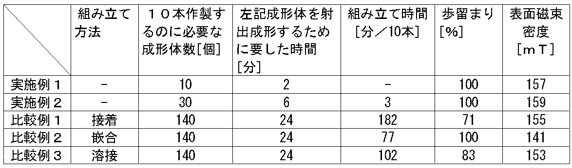
実施例1では、1回の成形工程で1本の円柱状ボンド磁石を作製することができるため、射出成形に要する時間が少ない。これに対して、比較例1乃至3では、円柱状ボンド磁石ピースを大量に作製する必要があるため、射出成形に要する時間が多くなってしまう。そして、比較例1乃至3では、円柱状ボンド磁石や棒状磁石体に組み上げるための時間が更に必要となる。比較例2については、表1には示していないが、円柱状ボンド磁石ピースを筒状に加工する時間や支持軸と留め具を作製する時間が必要である。これらのことからしても、本発明の円柱状ボンド磁石は、生産性に優れることが分かる。また、比較例1や比較例3では、接着不良や溶接不良によって、歩留まりが低下するが、本発明では、そのような操作を行う必要がないため、品質の高い円柱状ボンド磁石を生産性良く安全に提供することができる。
磁気特性について、実施例1と実施例2は、比較例1と比較例3と比較しても遜色のない特性が得られる。比較例2については、筒状磁石ピースを使用するため、特性は低下する。
また実施例2では、貼り合せ箇所を有するにも関わらず、その表面磁束密度分布は、連続した正弦波形のものが得られる。
以上のことから、本発明によれば、十分な磁気特性を有しつつ、従来にはない生産性に優れる円柱状ボンド磁石を提供することができる。
本発明の円柱状ボンド磁石は、異物除去装置やリニアモータ用の永久磁石材料として利用することができる。
1…キャビティ部
2…側壁
3…配向用磁石
4…エジェクターピン
5、5’…配向用磁石の接合体
6…筒状ボンド磁石
7…支持軸
8…留め具
2…側壁
3…配向用磁石
4…エジェクターピン
5、5’…配向用磁石の接合体
6…筒状ボンド磁石
7…支持軸
8…留め具
Claims (6)
- 磁性粉末と樹脂で構成された、外形を略円柱状とするボンド磁石であって、
前記円柱状ボンド磁石は、単一の成形体であり、
該円柱状の軸方向に、N極とS極が交互に現れるよう、多極磁化されている
ことを特徴とする円柱状ボンド磁石。 - 請求項1に記載の円柱状ボンド磁石であって、
少なくとも4極以上の偶数極に交互に多極磁化されていると共に、
前記円柱状ボンド磁石の側面の軸方向に沿って表面磁束を測定したときに、その表面磁束密度分布が、両端を節とした略正弦波形を示すことを特徴とする円柱状ボンド磁石。 - 請求項1または2に記載の円柱状ボンド磁石であって、
前記円柱状ボンド磁石の単一成形体が、射出成形によって成形されることを特徴とする円柱状ボンド磁石。 - 請求項1から3のいずれか一に記載の円柱状ボンド磁石であって、
前記磁性粉末が、異方性の希土類-鉄-窒素系合金粉末であることを特徴とする円柱状ボンド磁石。 - 請求項1から4のいずれか一に記載の円柱状ボンド磁石と、
前記円柱状ボンド磁石を少なくとも2個以上収納する非磁性パイプと
を備えた棒状磁石体であって、
前記非磁性パイプの側面の軸方向に沿って表面磁束を測定したときに、その表面磁束密度分布が、連続した略正弦波形を示すことを特徴とする棒状磁石体。 - 請求項1から5のいずれか一に記載される円柱状ボンド磁石の製造方法であって、
磁性粉末と樹脂を混練しコンパウンドを得る工程と、
配向磁場を印加しながら前記コンパウンドを円柱状ボンド磁石に成形する工程と、
を含んでおり、
前記配向磁場は、同種の磁極が対向するように複数の磁石を接合させた配向用磁石により形成され、前記配向用磁石は、前記円柱状ボンド磁石を囲むように設置されていることを特徴とする円柱状ボンド磁石の製造方法。
Priority Applications (1)
| Application Number | Priority Date | Filing Date | Title |
|---|---|---|---|
| US13/132,317 US8643453B2 (en) | 2008-12-08 | 2009-12-03 | Cylindrical bonded magnet, method for producing a cylindrical bonded magnet, and rod-shaped magnet device |
Applications Claiming Priority (4)
| Application Number | Priority Date | Filing Date | Title |
|---|---|---|---|
| JP2008312049 | 2008-12-08 | ||
| JP2008-312049 | 2008-12-08 | ||
| JP2009-170665 | 2009-07-22 | ||
| JP2009170665A JP4636198B2 (ja) | 2008-12-08 | 2009-07-22 | 円柱状ボンド磁石およびその製造方法並びに棒状磁石体 |
Publications (1)
| Publication Number | Publication Date |
|---|---|
| WO2010067553A1 true WO2010067553A1 (ja) | 2010-06-17 |
Family
ID=42242549
Family Applications (1)
| Application Number | Title | Priority Date | Filing Date |
|---|---|---|---|
| PCT/JP2009/006605 Ceased WO2010067553A1 (ja) | 2008-12-08 | 2009-12-03 | 円柱状ボンド磁石およびその製造方法並びに棒状磁石体 |
Country Status (3)
| Country | Link |
|---|---|
| US (1) | US8643453B2 (ja) |
| JP (1) | JP4636198B2 (ja) |
| WO (1) | WO2010067553A1 (ja) |
Cited By (1)
| Publication number | Priority date | Publication date | Assignee | Title |
|---|---|---|---|---|
| JP2014063983A (ja) * | 2012-09-20 | 2014-04-10 | Korea Atomic Energy Research Inst | 永久磁石を用いた磁気装置 |
Families Citing this family (6)
| Publication number | Priority date | Publication date | Assignee | Title |
|---|---|---|---|---|
| JP5463773B2 (ja) * | 2009-07-21 | 2014-04-09 | 日亜化学工業株式会社 | 柱状ボンド磁石の製造方法 |
| TWI442074B (zh) * | 2011-09-23 | 2014-06-21 | Acer Inc | 電子裝置與防呆方法 |
| KR102102498B1 (ko) * | 2012-12-07 | 2020-04-20 | 콘티넨탈 테베스 아게 운트 코. 오하게 | 영구 자석의 각도 에러의 정정 |
| CN103236335A (zh) * | 2013-04-23 | 2013-08-07 | 哈姆林电子(苏州)有限公司 | 一种注塑磁铁及其制作方法 |
| EP3270389B1 (de) * | 2016-07-12 | 2019-04-10 | Ncte Ag | Magnetisierung einer hohlwelle |
| RU175441U1 (ru) * | 2017-06-05 | 2017-12-05 | Федеральное государственное бюджетное образовательное учреждение высшего образования "Саратовский государственный технический университет имени Гагарина Ю.А." (СГТУ имени Гагарина Ю.А.) | Магнитная периодическая фокусирующая система |
Citations (5)
| Publication number | Priority date | Publication date | Assignee | Title |
|---|---|---|---|---|
| JPS63228707A (ja) * | 1987-03-18 | 1988-09-22 | Sumitomo Bakelite Co Ltd | 異方性多極プラスチツク磁石の製造方法 |
| JPH08130862A (ja) * | 1994-11-02 | 1996-05-21 | Sumitomo Special Metals Co Ltd | 磁石可動形リニアアクチュエータ |
| JPH09191633A (ja) * | 1996-01-11 | 1997-07-22 | Matsushita Electric Ind Co Ltd | リニアサーボコイル |
| JP2004320827A (ja) * | 2003-04-11 | 2004-11-11 | Toda Kogyo Corp | 往復運動装置用磁石及びこれを用いた往復運動装置 |
| WO2006106697A1 (ja) * | 2005-03-30 | 2006-10-12 | Thk Co., Ltd. | リニアモータアクチュエータ |
Family Cites Families (17)
| Publication number | Priority date | Publication date | Assignee | Title |
|---|---|---|---|---|
| BE521065A (ja) * | 1952-07-01 | |||
| DE1053687B (de) * | 1954-04-22 | 1959-03-26 | Philips Nv | Magnetsystem mit zwei um mindestens eine Polteilung gegeneinander verschiebbaren Magnet-anordnungen |
| US3034651A (en) * | 1960-03-16 | 1962-05-15 | Don P Morrell | Magnetic filter cartridge |
| US3153177A (en) * | 1962-09-11 | 1964-10-13 | Ketcham And Mcdougall Inc | Magnetic holder for paper clips |
| US4689163A (en) * | 1986-02-24 | 1987-08-25 | Matsushita Electric Industrial Co., Ltd. | Resin-bonded magnet comprising a specific type of ferromagnetic powder dispersed in a specific type of resin binder |
| USRE34443E (en) * | 1986-03-05 | 1993-11-16 | Hitachi, Ltd. | Apparatus magnetically detecting position or speed of moving body utilizing bridge circuit with series connected MR elements |
| GB9215110D0 (en) * | 1992-07-16 | 1992-08-26 | Cookson Group Plc | Method for the fabrication of multipole magnets |
| JPH06349630A (ja) * | 1993-06-14 | 1994-12-22 | Kawasaki Steel Corp | 異方性磁石 |
| JPH08331784A (ja) * | 1995-03-24 | 1996-12-13 | Hitachi Metals Ltd | 永久磁石界磁方式回転機 |
| US6160465A (en) * | 1997-11-07 | 2000-12-12 | Murata Manufacturing Co. Ltd. | High-frequency choke coil |
| TW476180B (en) * | 1999-09-30 | 2002-02-11 | Sanyo Electric Co | Permanent magnet stepping motor |
| JP2001231245A (ja) * | 2000-02-10 | 2001-08-24 | Bridgestone Corp | リニアモータ用ガイドシャフトの製造方法及びガイドシャフト成形金型 |
| JP2003257762A (ja) * | 2002-02-27 | 2003-09-12 | Hitachi Ltd | リング磁石とその製造法及び回転子と回転機並びにその磁界発生装置及びリング磁石製造装置 |
| JP2003303714A (ja) | 2002-04-09 | 2003-10-24 | Sumitomo Special Metals Co Ltd | 棒磁石および磁性体除去装置 |
| JP2005073466A (ja) | 2003-08-27 | 2005-03-17 | Koyo Seiko Co Ltd | リニアモータ |
| WO2005104337A1 (ja) * | 2004-04-20 | 2005-11-03 | Aichi Steel Corporation | 4磁極モータ用異方性ボンド磁石、それを用いたモータ及び4磁極モータ用異方性ボンド磁石の配向処理装置 |
| JP5268309B2 (ja) | 2006-12-26 | 2013-08-21 | Thk株式会社 | ロッドリニアアクチュエータ |
-
2009
- 2009-07-22 JP JP2009170665A patent/JP4636198B2/ja active Active
- 2009-12-03 WO PCT/JP2009/006605 patent/WO2010067553A1/ja not_active Ceased
- 2009-12-03 US US13/132,317 patent/US8643453B2/en not_active Expired - Fee Related
Patent Citations (5)
| Publication number | Priority date | Publication date | Assignee | Title |
|---|---|---|---|---|
| JPS63228707A (ja) * | 1987-03-18 | 1988-09-22 | Sumitomo Bakelite Co Ltd | 異方性多極プラスチツク磁石の製造方法 |
| JPH08130862A (ja) * | 1994-11-02 | 1996-05-21 | Sumitomo Special Metals Co Ltd | 磁石可動形リニアアクチュエータ |
| JPH09191633A (ja) * | 1996-01-11 | 1997-07-22 | Matsushita Electric Ind Co Ltd | リニアサーボコイル |
| JP2004320827A (ja) * | 2003-04-11 | 2004-11-11 | Toda Kogyo Corp | 往復運動装置用磁石及びこれを用いた往復運動装置 |
| WO2006106697A1 (ja) * | 2005-03-30 | 2006-10-12 | Thk Co., Ltd. | リニアモータアクチュエータ |
Cited By (1)
| Publication number | Priority date | Publication date | Assignee | Title |
|---|---|---|---|---|
| JP2014063983A (ja) * | 2012-09-20 | 2014-04-10 | Korea Atomic Energy Research Inst | 永久磁石を用いた磁気装置 |
Also Published As
| Publication number | Publication date |
|---|---|
| JP4636198B2 (ja) | 2011-02-23 |
| US8643453B2 (en) | 2014-02-04 |
| JP2010161333A (ja) | 2010-07-22 |
| US20110241811A1 (en) | 2011-10-06 |
Similar Documents
| Publication | Publication Date | Title |
|---|---|---|
| JP4636198B2 (ja) | 円柱状ボンド磁石およびその製造方法並びに棒状磁石体 | |
| US8039998B2 (en) | Rotor for motor and method for producing the same | |
| KR100869999B1 (ko) | 레이디얼 이방성 링 자석 및 그 제조방법 | |
| JP6920812B2 (ja) | 複数磁化ユニット永久磁石、その製造方法、金型、及び磁気回路 | |
| JP6870356B2 (ja) | 異方性ボンド磁石の成形用金型及びこれを用いた製造方法 | |
| JP2005064448A (ja) | 積層極異方複合磁石の製造方法 | |
| TWI289967B (en) | Anisotropic bond magnet for four-magnetic-pole motor, motor using the same, device for orientation processing of anisotropic bond magnet for four-magnetic-pole motor | |
| JP5530707B2 (ja) | 円柱状ボンド磁石およびその製造方法並びに製造装置 | |
| JP4701641B2 (ja) | 複合ボンド磁石、複合ボンド磁石の製造方法、複合ボンド磁石を搭載したdcブラシレスモータの回転子。 | |
| JP5884425B2 (ja) | 円柱状ボンド磁石の製造方法 | |
| US10232538B2 (en) | Bond magnet and method for manufacturing the same | |
| EP1717828A1 (en) | Methods of producing radial anisotropic cylinder sintered magnet and permanent magnet motor-use cylinder multi-pole magnet | |
| JPWO2010029642A1 (ja) | 希土類異方性ボンド磁石の製造方法、磁石成形体の配向処理方法および磁場中成形装置 | |
| JP4577604B2 (ja) | 異方性希土類ボンド磁石の製造方法 | |
| JP5463773B2 (ja) | 柱状ボンド磁石の製造方法 | |
| JP2007214393A (ja) | リング状の極異方性プラスチック磁石及びモータ用ロータ | |
| JP5532898B2 (ja) | 棒状ボンド磁石およびその製造方法 | |
| JP5870523B2 (ja) | ボンド磁石およびその製造方法並びにボンド磁石の製造装置 | |
| JP5651944B2 (ja) | 円柱状ボンド磁石の製造方法 | |
| JPS6252913A (ja) | 多極異方性円筒状磁石の製造方法及び装置 | |
| JPH07250460A (ja) | 極磁場配向用ダイスおよび可撓性マグネットの製造方法 | |
| CN100521458C (zh) | 应用于4磁极电机的各向异性粘结磁铁和使用了该磁铁的电机、以及应用于4磁极电机的各向异性粘结磁铁的磁场定向处理装置 | |
| JP6056141B2 (ja) | 円筒状ボンド磁石の製造方法およびその製造装置 | |
| JP2011029215A (ja) | 筒状ボンド磁石及びその製造方法 | |
| JP2023054983A (ja) | 磁石埋込型モータのロータ構造およびその製造方法 |
Legal Events
| Date | Code | Title | Description |
|---|---|---|---|
| 121 | Ep: the epo has been informed by wipo that ep was designated in this application |
Ref document number: 09831661 Country of ref document: EP Kind code of ref document: A1 |
|
| WWE | Wipo information: entry into national phase |
Ref document number: 13132317 Country of ref document: US |
|
| NENP | Non-entry into the national phase |
Ref country code: DE |
|
| 122 | Ep: pct application non-entry in european phase |
Ref document number: 09831661 Country of ref document: EP Kind code of ref document: A1 |