WO2010061848A1 - フロントフォークのオイルロック装置 - Google Patents
フロントフォークのオイルロック装置 Download PDFInfo
- Publication number
- WO2010061848A1 WO2010061848A1 PCT/JP2009/069855 JP2009069855W WO2010061848A1 WO 2010061848 A1 WO2010061848 A1 WO 2010061848A1 JP 2009069855 W JP2009069855 W JP 2009069855W WO 2010061848 A1 WO2010061848 A1 WO 2010061848A1
- Authority
- WO
- WIPO (PCT)
- Prior art keywords
- oil
- valve
- flow path
- hollow rod
- collar
- Prior art date
- Legal status (The legal status is an assumption and is not a legal conclusion. Google has not performed a legal analysis and makes no representation as to the accuracy of the status listed.)
- Ceased
Links
Images










Classifications
-
- B—PERFORMING OPERATIONS; TRANSPORTING
- B62—LAND VEHICLES FOR TRAVELLING OTHERWISE THAN ON RAILS
- B62K—CYCLES; CYCLE FRAMES; CYCLE STEERING DEVICES; RIDER-OPERATED TERMINAL CONTROLS SPECIALLY ADAPTED FOR CYCLES; CYCLE AXLE SUSPENSIONS; CYCLE SIDECARS, FORECARS, OR THE LIKE
- B62K25/00—Axle suspensions
- B62K25/04—Axle suspensions for mounting axles resiliently on cycle frame or fork
- B62K25/06—Axle suspensions for mounting axles resiliently on cycle frame or fork with telescopic fork, e.g. including auxiliary rocking arms
- B62K25/08—Axle suspensions for mounting axles resiliently on cycle frame or fork with telescopic fork, e.g. including auxiliary rocking arms for front wheel
-
- F—MECHANICAL ENGINEERING; LIGHTING; HEATING; WEAPONS; BLASTING
- F16—ENGINEERING ELEMENTS AND UNITS; GENERAL MEASURES FOR PRODUCING AND MAINTAINING EFFECTIVE FUNCTIONING OF MACHINES OR INSTALLATIONS; THERMAL INSULATION IN GENERAL
- F16F—SPRINGS; SHOCK-ABSORBERS; MEANS FOR DAMPING VIBRATION
- F16F9/00—Springs, vibration-dampers, shock-absorbers, or similarly-constructed movement-dampers using a fluid or the equivalent as damping medium
- F16F9/32—Details
- F16F9/48—Arrangements for providing different damping effects at different parts of the stroke
- F16F9/49—Stops limiting fluid passage, e.g. hydraulic stops or elastomeric elements inside the cylinder which contribute to changes in fluid damping
-
- B—PERFORMING OPERATIONS; TRANSPORTING
- B62—LAND VEHICLES FOR TRAVELLING OTHERWISE THAN ON RAILS
- B62K—CYCLES; CYCLE FRAMES; CYCLE STEERING DEVICES; RIDER-OPERATED TERMINAL CONTROLS SPECIALLY ADAPTED FOR CYCLES; CYCLE AXLE SUSPENSIONS; CYCLE SIDECARS, FORECARS, OR THE LIKE
- B62K25/00—Axle suspensions
- B62K25/04—Axle suspensions for mounting axles resiliently on cycle frame or fork
- B62K2025/044—Suspensions with automatic adjustment
Definitions
- the present invention relates to an oil lock device for a front fork such as a motorcycle.
- an inner tube on the vehicle body side is slidably fitted into an outer tube on the wheel side, and the inner tube is slid onto the inner periphery of the inner tube.
- a hollow rod provided with a partition wall that comes into contact is erected, and an oil chamber in which a piston valve provided at the inner periphery of the inner end of the inner tube advances and retreats is defined on the outer periphery of the hollow rod, and an upper portion is defined as an air chamber on the inner periphery of the hollow rod.
- a piston valve is provided, and an annular inner peripheral flow path is formed between the inner periphery of the piston valve and the outer periphery of the hollow rod, and a ring is formed between the outer periphery of the piston valve and the inner periphery of the inner tube.
- the upper and lower annular valve seats that contact the upper and lower end surfaces of the piston valve are provided on the inner periphery of the tip of the inner tube, and the upper and lower valve seats are in contact with the outer periphery of the hollow rod.
- a flow path that communicates the outer peripheral flow path with the oil chamber is provided, and a notch that penetrates in the radial direction is formed on the upper and lower end faces of the piston valve.
- the piston valve moves downward and comes into contact with the lower valve seat.
- the hydraulic oil in the upper oil chamber above the piston valve is divided into a flow path formed between the upper valve seat and a notch on the upper end surface of the piston valve, an inner peripheral flow path and an outer peripheral flow path of the piston valve, and a piston valve.
- the hydraulic oil in the upper oil chamber above the piston valve is formed by a flow path formed between the upper valve seat and the notch on the upper end surface of the piston valve, and the inner peripheral flow path of the piston valve.
- the outer peripheral side flow path, the notch portion of the lower end surface of the piston valve passes through the flow path formed between the lower valve seat, and flows into the lower oil chamber below the piston valve to generate the extension side damping force.
- hydraulic oil corresponding to the withdrawal volume of the inner tube exiting from the oil chamber on the outer periphery of the hollow rod flows into the lower oil chamber from the oil reservoir chamber through the lower oil hole of the hollow rod.
- Patent Document 1 uses a single piston valve to generate a damping force on the compression side and the extension side, and constitutes an oil lock device, and has the following problems.
- the problem of the present invention is that in the oil lock device of the front fork, the damping force on the compression side and the extension side can be adjusted independently of each other, a sufficient oil lock load can be obtained, and when reversing from the most compressed state to the extension stroke It is also to prevent the sound from coming off.
- a hollow rod having a vehicle body side inner tube slidably fitted in a wheel side outer tube and having a partition wall portion slidably in contact with an inner periphery of the inner tube at a bottom portion of the outer tube.
- An oil chamber is provided on the outer periphery of the hollow rod, and an oil chamber in which the piston provided at the inner periphery of the inner end of the inner tube advances and retreats.
- An oil reservoir chamber having an upper portion as an air chamber is defined on the inner periphery of the hollow rod.
- the piston is located above the upper seating surface of the collar provided on the inner periphery of the inner end of the inner tube.
- a valve is provided, a lower valve is provided at the lower part of the lower seating surface of the collar, an upper valve seat is provided at the upper part of the upper valve, and a lower valve seat is provided at the lower part of the lower valve.
- Upper valve It can be moved between the collars, and can be contacted and separated from the collar seating surface, and an inner peripheral flow path is formed between the hollow rod outer periphery and an outer peripheral flow path is formed between the inner tube inner periphery and the inner tube inner periphery.
- the lower valve moves between the lower seating surface of the collar and the lower valve seat, can contact with and separate from the lower seating surface of the collar, and forms an inner peripheral flow path between the outer periphery of the hollow rod and the inner tube.
- An outer peripheral flow path is formed between the upper valve seat and the outer periphery of the hollow rod, and a flow path is provided between the upper valve seat and the oil chamber.
- the lower valve seat is a hollow rod.
- a flow path is provided between the outer circumference and a flow path that communicates the flow path on the outer circumference side of the lower valve with the oil chamber. In the most compression stroke, the upper valve does not at least completely close the oil hole, and the lower valve It is located on the lower end side of the hollow rod from the hole.
- the upper seating surface or the lower seating surface of the collar is tapered.
- the upper seating surface or the lower seating surface of the collar is tapered.
- the upper seating surface of the collar forms the outer peripheral flow path of the upper valve that flows into the upper oil chamber after the oil in the lower oil chamber below the piston passes through the inner peripheral flow path of the lower valve in the compression stroke
- the oil flow in this compression stroke is made smooth along the tapered shape of the upper seating surface.
- the lower seating surface of the collar forms an outer peripheral flow path of the lower valve that flows into the lower oil chamber after the oil in the upper oil chamber of the upper part of the piston passes through the inner peripheral flow path of the upper valve in the extension stroke. Therefore, the flow of the oil in the extension stroke is made smooth along the tapered shape of the lower seating surface.
- the flow path on the outer side of the lower valve that causes the oil in the oil reservoir chamber and the upper oil chamber described in (c) above to flow into the lower oil chamber (oil lock chamber) when the extension stroke is reversed from the most compression stroke is a tapered shape of the collar.
- the oil flow is made smoother along the taper shape of the lower seating surface, and the negative pressure in the oil lock oil chamber is eliminated more smoothly, further eliminating the noise during the extension stroke. Make sure to prevent it.
- the upper valve or the lower valve further includes a centering protrusion that protrudes at a plurality of positions in the circumferential direction of the inner diameter and contacts the outer periphery of the hollow rod. It is.
- the upper valve or the lower valve includes centering protrusions that protrude at a plurality of positions in the circumferential direction of the inner diameter and contact the outer periphery of the hollow rod. Therefore, the upper valve or the lower valve is maintained centered with respect to the outer periphery of the hollow rod, and as a result, the shape of the inner peripheral flow path is stabilized, and the generated damping force of (a) is stabilized.
- the upper valve in the invention according to any one of the first to third aspects, can be in line contact with the entire circumference of the upper seating surface of the collar without a gap, or the lower valve can be entirely in contact with the lower seating surface of the collar. It is designed to allow line contact without any gap around the circumference.
- the annular outer peripheral surface of the lower valve can be in line contact with the entire circumference of the lower seating surface of the collar without any gaps, the lower valve is in line contact with the entire circumference of the lower seating surface of the collar to ensure its sealing performance.
- a constant throttle flow path is formed by the inner peripheral flow path of the lower valve of the above-described (a), and a constant compression side damping force is generated.
- the invention of claim 5 is the invention according to any one of claims 1 to 4, wherein the upper valve or the lower valve is prepared and used in a plurality of types having different inner diameter shapes. .
- the upper valve and the lower valve are shared with each other.
- the invention of claim 7 is the invention according to any one of claims 1 to 6, wherein the upper valve seat and the lower valve seat form a flat plate shape.
- the upper valve seat and the lower valve seat have a flat plate shape, the upper valve seat and the lower valve seat can be easily produced (for example, one-step press processing), and the cost can be reduced.
- the invention of claim 8 is the invention according to any one of claims 1 to 7, wherein the upper valve seat and the lower valve seat are used in common.
- the upper valve seat and the lower valve seat are provided on the inner periphery of the inner end of the inner tube and are shared, and the number of parts of the front fork can be reduced.
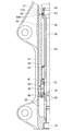
- FIG. 1 is an overall cross-sectional view showing a front fork of the first embodiment.
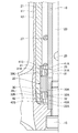
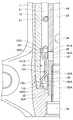
- FIG. 2 is a half sectional view showing the lower structure of the front fork.
- FIG. 3 is a half sectional view showing a compression stroke of the front fork.
- FIG. 4 is a half sectional view showing the most compressed state of the front fork.
- FIG. 5 is a half sectional view showing the extension stroke of the front fork.
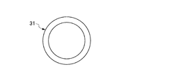
- FIG. 6 is a plan view showing the upper valve.
- FIG. 7 shows an upper valve seat, (A) is a sectional view, and (B) is a bottom view.
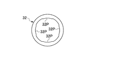
- FIG. 8 is a plan view showing the lower valve.
- FIG. 9 shows a lower valve seat, (A) is a sectional view, and (B) is a top view.
- FIG. 10 shows a check valve, where (A) is a cross-sectional view and (B) is a bottom view.
- FIG. 11 is a half sectional view showing an oil lock device for a front fork according to the second embodiment.
- FIG. 12 is a half sectional view showing the compression stroke of the front fork.
- FIG. 13 is a half sectional view showing the most compressed state of the front fork.
- FIG. 14 is a half sectional view showing the extension stroke of the front fork.
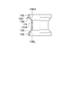
- FIG. 15 is a cross-sectional view showing a collar.
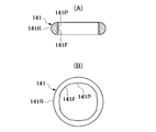
- FIG. 16 shows an upper valve, (A) is a cross-sectional view, and (B) is a plan view.
- FIG. 17 shows an upper valve seat, (A) is a sectional view, and (B) is a plan view.
- FIG. 18A and 18B show the lower valve, where FIG. 18A is a cross-sectional view and FIG. 18B is a plan view.
- FIG. 19 shows a lower valve seat, (A) is a sectional view, and (B) is a plan view.
- Example 1 (FIGS. 1 to 10) As shown in FIGS. 1 and 2, a front fork 10 such as a motorcycle has a vehicle body side inner tube 12 slidably fitted in a wheel side outer tube 11. A dust seal 13 and an oil seal 14 are provided at the opening end of the outer tube 11 where the inner tube 12 is inserted.
- a bolt 15 is inserted into the bottom of the outer tube 11, and a hollow rod 16 is erected by the bolt 15.
- the upper end portion of the hollow rod 16 is enlarged in diameter to form a partition portion 17 that is in sliding contact with the inner periphery of the inner tube 12.
- a check valve 50 (described later) made of a piston ring is provided in a ring groove 17 ⁇ / b> A provided on the outer periphery of the partition wall portion 17, and the check valve 50 is slidably contacted with the inner periphery of the inner tube 12.
- a suspension spring 19 is interposed between the upper end surface of the partition wall 17 of the hollow rod 16 and the spring seat 18 provided at the upper end of the inner tube 12.
- the spring sheet 18 is sealed to the inner diameter of the upper end of the inner tube 12 via an O-ring 18A and is held by a stopper ring 18B.
- the front fork 10 is provided with a piston 20 at the inner periphery of the inner end of the inner tube 12.
- the upper and lower oil chambers 21 and 22 where the piston 20 advances and retreats are defined on the outer periphery of the hollow rod 16.
- An oil reservoir chamber 23, which is a chamber 24, is partitioned, and an oil hole 25 that communicates between the oil chambers 21 and 22 and the oil reservoir chamber 23 is provided below the hollow rod 16.
- the oil reservoir chamber 23 extends to the inside of the inner tube 12, and the air chamber 24 is sealed with a spring seat 18 at the upper end portion of the inner tube 12.
- the oil holes 25 are formed at a plurality of positions in the axial direction and the circumferential direction of the hollow rod 16.
- the piston 20 is provided with a collar 30 made of an annular body on the inner periphery of the inner end of the inner tube 12, and an upper valve 31 is provided on an upper seating surface 30 ⁇ / b> U as an upper end surface of the collar 30 so as to be able to contact and separate.
- a lower valve 32 is provided on the surface 30L so as to be able to contact and separate.
- the piston 20 is provided with an upper valve seat 41 at the upper part of the upper valve 31 and a lower valve seat 42 at the lower part of the lower valve 32.
- the collar 30 of the piston 20 and the upper and lower valve seats 41, 42 are caulked and fixed to the inner tube 12.
- the collar 30 forms an annular flow path 30 ⁇ / b> A between the outer periphery of the hollow rod 16.
- the upper valve 31 is formed of an annular body as shown in FIG. 6 and is housed in the inner periphery of the upper valve seat 41 via a wide annular gap.
- the upper seating surface 30U of the collar 30 and the upper end stopper 41S of the upper valve seat 41 are In between, it slides on the outer periphery of the hollow rod 16 and moves up and down.
- the upper valve 31 seals the upper seating surface 30U of the collar 30 with its lower end face in contact with the upper end without any gap when moving downward, and the upper end face abuts with the upper end stopper 41S of the upper valve seat 41 when moving upward from the collar 30.
- An annular inner peripheral flow path 31A is formed between the hollow rod 16 and the outer periphery of the hollow rod 16, and an annular outer peripheral side is formed between the inner periphery of the inner tube 12 (the inner periphery of the upper valve seat 41 in this embodiment).
- a flow path 31B is formed.
- the inner peripheral flow path 31A of the upper valve 31 is an expansion side throttle flow path.
- the lower valve 32 is formed of an annular body as shown in FIG. 8 and is housed in the inner periphery of the lower valve seat 42 through a wide annular gap.
- the lower seating surface 30L of the collar 30 and the lower end stopper 42S of the lower valve seat 42 are provided. In between, it slides on the outer periphery of the hollow rod 16 and moves up and down.
- the lower valve 32 seals the lower seating surface 30L of the collar 30 with its upper end face in contact with the upper end without any gap when moving upward, and the lower end face abuts against the lower end stopper 42S of the lower valve seat 42 when moving downward from the collar 30.
- An annular inner circumferential flow path 32A is formed between the outer periphery of the hollow rod 16 and an annular outer circumferential side between the inner periphery of the inner tube 12 (the inner periphery of the lower valve seat 42 in this embodiment).
- a flow path 32B is formed.
- the inner peripheral side flow path 32A of the lower valve 32 becomes a pressure side throttle flow path.
- the lower valve 32 includes a centering protrusion 32P that protrudes in the radial direction at four positions in the circumferential direction of the inner diameter and contacts the outer periphery of the hollow rod 16, as shown in FIG.
- the upper valve 31 can also be provided with a similar centering protrusion.
- the upper valve seat 41 is formed of an annular body as shown in FIG. 7 and includes an upper end stopper 41S that protrudes inward from four circumferential positions on the inner periphery of the upper end of the annular body.
- the upper valve seat 41 forms an upper flow path 41 ⁇ / b> A that communicates the inner peripheral flow path 31 ⁇ / b> A and the outer peripheral flow path 31 ⁇ / b> B of the upper valve 31 with the upper oil chamber 21 between the outer periphery of the hollow rod 16.
- the lower valve seat 42 is formed of an annular body as shown in FIG. 9 and includes a lower end stopper 42S that protrudes inward from four circumferential positions on the inner periphery of the lower end of the annular body.
- the lower valve seat 42 forms a lower flow path 42 ⁇ / b> A that connects the inner peripheral flow path 32 ⁇ / b> A and the outer peripheral flow path 32 ⁇ / b> B of the lower valve 32 to the lower oil chamber 22 between the lower valve seat 42 and the outer periphery of the hollow rod 16.
- the upper valve 31 does not close the oil hole 25 at least completely, and the lower valve 32 is positioned on the lower end side of the hollow rod 16 from the oil hole 25 in the most compression stroke (FIG. 4).
- the upper valve 31 partially opens the oil hole 25 provided on the lower end side among the plurality of oil holes 25 of the hollow rod 16, and the oil reservoir chamber 23 communicates with the annular flow path 30 ⁇ / b> A of the collar 30. I am letting.
- the lower valve 32 is located further on the lower end side of the hollow rod 16 than the oil hole 25 provided on the lower end side of the hollow rod 16.
- the front fork 10 is provided with a plurality of types of upper valves 31 or lower valves 32 having different inner diameter shapes, in other words, a plurality of types having different throttle characteristics due to the shapes of the inner diameters. You can choose to use it. Further, the upper valve 31 and the lower valve 32 can be shared with each other.
- the check valve 50 is composed of a C-shaped piston ring that is mounted on the outer periphery of the partition wall 17 of the hollow rod 16 so as to be movable up and down.
- the check valve 50 is in sliding contact with the inner periphery of the inner tube 12, and the ring groove 17A.
- An annular channel 51 is formed between the bottom of the groove.
- the check valve 50 includes a notch 50 ⁇ / b> A penetrating in the radial direction on the lower end surface of the ring groove 17 ⁇ / b> A of the partition wall 17 that is in contact with the lower groove side wall near the upper oil chamber 21.
- the check valve 50 moves downward (moves downward as the inner tube 12 moves relative to the hollow rod 16 downward), and the upper end surface of the check valve 50 and the ring portion 17 ring A valve is formed between the upper groove side wall of the groove 17A and the valve is opened, and the hydraulic oil in the oil reservoir 23 at the upper part of the partition wall 17 passes through the annular channel 51 and the cutout 50A, and the outer periphery of the hollow rod 16 Flow into the upper oil chamber 21 to prevent negative pressure in the upper oil chamber 21, and (b) during the extension stroke, the oil is moved upward (the oil pressure in the upper oil chamber 21 is increased and the inner tube 12 is hollowed The upper end surface of the check valve 50 is brought into close contact with the upper groove side wall portion of the ring groove 17A of the partition wall portion 17 to close the outer periphery of the hollow rod 16. The hydraulic oil in the oil chamber 21 flows into the oil reservoir chamber 23 above the partition wall portion 17. To prevent Rukoto.
- the front fork 10 is provided with an oil hole (small hole) 26 communicating with the upper oil chamber 21 and the oil reservoir 23 in the hollow rod 16, and this oil hole (small hole) is used during the extension stroke to use the upper oil chamber 21. Based on the passage resistance of the oil flowing out from the oil reservoir chamber 23, the extension side damping force is generated.
- a rebound spring 27 at the maximum extension is provided between the upper valve seat 41 provided on the inner tube 12 and the partition wall 17 of the hollow rod 16.
- the impact received by the wheels is absorbed and buffered by the suspension spring 19 and the air spring of the air chamber 24, and the expansion and contraction vibration of the suspension spring 19 due to the absorption of the impact is absorbed by the oil chamber 21, Suppressed by the damping force generated at 22.
- the front fork 10 performs a damping action as follows. (Compression process)
- the pressure in the lower oil chamber 22 below the piston 20 whose volume is reduced increases.
- the lower valve 32 of the piston 20 moves upward to contact and seal the lower seating surface 30L of the collar 30 without any gap, and the upper valve 31 moves upward to abut the upper end stopper 41S of the upper valve seat 41.
- the hydraulic oil in the lower oil chamber 22 below the piston 20 passes through the lower flow path 42A of the lower valve seat 42, the inner peripheral flow path 32A (pressure side throttle flow path) of the lower valve 32, and the annular flow path 30A of the collar 30.
- the hydraulic oil corresponding to the volume of entry of the inner tube 12 into the oil chambers 21 and 22 passes through the plurality of oil holes 25 formed in the lower portion of the hollow rod 16 from the lower oil chamber 22, and the inside of the hollow rod 16. It flows to the peripheral oil reservoir 23.
- the compression side damping force is generated by the plurality of oil holes 25.
- the lower oil chamber 22 (oil lock oil chamber 22A) below the piston 20 ) Passes through only the lower flow path 42A of the lower valve seat 42 and the inner flow path 32A (pressure side throttle flow path) of the lower valve 32, and then from the annular flow path 30A of the collar 30 to the upper valve 31.
- the oil flows to the upper oil chamber 21 via the outer flow passage 31B and the upper flow passage 41A of the upper valve seat 41 or to the oil reservoir chamber 23 via the oil hole 25.
- the upper valve 31 does not completely close the oil hole 25, and the lower valve 32 is positioned on the lower end side of the hollow rod 16 from the oil hole 25.
- the oil pressure Pa in the oil reservoir 23 reaches the upper portion of the upper valve 32 via the annular flow path 30 ⁇ / b> A of the collar 30.
- the lower valve 32 flows to the lower oil chamber 22 via the outer flow path 32B of the lower valve 32 and the lower flow path 42A of the lower valve seat 42, and the extended side based on the restriction resistance of the inner flow path 31A due to the inner diameter shape of the upper valve 31. Damping force is generated.
- the hydraulic oil in the upper oil chamber 21 above the piston 20 passes through an oil hole (small hole) 26 drilled in the upper part of the hollow rod 16 and flows into the oil reservoir chamber 23 on the inner periphery of the hollow rod 16. Also generates an extensional damping force.
- the oil hole (small hole) 26 may not be provided.
- the following operational effects can be obtained.
- the extension stroke in the process in which the oil in the upper oil chamber 21 above the piston 20 flows to the lower oil chamber 22 through the inner peripheral flow path 31A of the upper valve 31 serving as the throttle flow path 31A, Is generated. Therefore, the throttle channel for generating the compression side and extension side damping forces is a separate channel, and these damping forces can be adjusted independently of each other.
- the upper valve 31 or the lower valve 32 includes a centering protrusion 32P that protrudes at a plurality of positions in the circumferential direction of the inner diameter and contacts the outer periphery of the hollow rod 16. Therefore, the upper valve 31 or the lower valve 32 is maintained centered with respect to the outer periphery of the hollow rod 16, and as a result, the shapes of the inner peripheral flow paths 31A and 32A are stabilized, and the generated damping force of (a) is reduced. Stabilize.
- (E) A plurality of types of the upper valve 31 or the lower valve 32 having different inner diameter shapes are prepared and used. Therefore, the shapes of the inner peripheral flow paths 31A and 32A of the upper valve 31 or the lower valve 32 can be selectively applied, and the characteristics of the generated damping force (a) can be diversified.
- Example 2 (FIGS. 11 to 19) The front fork 10 of the second embodiment is different from the first embodiment in the structure of the piston 20.
- the piston 20 of Example 2 was provided with a collar 130 on the inner periphery of the inner end of the inner tube 12 as shown in FIG.
- the collar 130 is an annular body as shown in FIG. 15 and can be manufactured by pressing from a pipe material.
- the intermediate portion in the axial direction is a small diameter cylindrical portion 131 and both end portions are large diameter cylindrical portions 132 and 132.
- the boundary portion between the small diameter cylindrical portion 131 and the large diameter cylindrical portion 132 is a tapered portion 133.
- the large-diameter cylindrical portion 132 at both ends of the collar 130 can be fitted to the inner periphery of the distal end portion of the inner tube 12, and the small-diameter cylindrical portion 131 forms an annular flow path 130 ⁇ / b> A with the outer periphery of the hollow rod 16. Holes 131 ⁇ / b> A are opened at a plurality of positions in the circumferential direction of the small diameter cylindrical portion 131.
- the piston 20 is provided with an upper valve 141 in an upper portion of a tapered upper seating surface 130U formed by the upper tapered portion 133 of the collar 130 so as to be able to contact and separate, and a tapered lower seating surface formed by the lower tapered portion 133 of the collar 130.
- a lower valve 142 is provided in a lower part of 130L so as to be able to contact and separate.
- the piston 20 is provided with an upper valve seat 151 on the upper part of the upper valve 141 and a lower valve seat 152 on the lower part of the lower valve 142.
- the collar 130 of the piston 20 and the upper and lower valve seats 151 and 152 are fitted to the inner periphery of the tip of the inner tube 12 and fixed by crimping.
- the upper valve 141 is interposed between the upper seating surface 130U of the collar 130 and the upper valve seat 151.
- the lower valve 142 is loaded between the lower seating surface 130 ⁇ / b> L of the collar 130 and the lower valve seat 152.
- the upper valve 141 is formed of an annular body as shown in FIG. 16, and the radial cross section thereof has a cylindrical inner peripheral surface 141F and an arc-shaped outer peripheral surface 141R.
- the upper valve 141 is housed between the upper seating surface 130U of the collar 130 and the outer periphery of the hollow rod 16, and the outer periphery of the hollow rod 16 is between the upper seating surface 130U of the collar 130 and the upper end stopper 151S of the upper valve seat 151. Slide up and down to move up and down.
- the upper valve 141 is sealed by linear contact with the lower surface of the arc-shaped outer peripheral surface 141R without gaps on the entire circumference of the upper seating surface 130U of the collar 130 during the downward movement, and the cylindrical inner peripheral surface 141F is the outer periphery of the hollow rod 16.
- An inner circumferential flow path 141 ⁇ / b> A composed of an annular minute gap is formed therebetween.
- the lower valve 142 is made of an annular body as shown in FIG. 18, and has a cylindrical inner peripheral surface 142F and an arc-shaped outer peripheral surface 142R in the cross section on the radius.
- the lower valve 142 is housed between the lower seating surface 130 ⁇ / b> L of the collar 130 and the outer periphery of the hollow rod 16, and between the lower seating surface 130 ⁇ / b> L of the collar 130 and the lower end stopper 152 ⁇ / b> S of the lower valve seat 152. Slide up and down to move up and down.
- the lower valve 142 is sealed by linearly contacting the upper surface of the arc-shaped outer peripheral surface 142R without gaps on the entire circumference of the lower seating surface 130L of the collar 130 during the downward movement, and the cylindrical inner peripheral surface 142F is the outer periphery of the hollow rod 16.
- 142A of inner peripheral side which consists of a cyclic
- the inner peripheral side flow path 142A of the lower valve 142 becomes a pressure side throttle path.
- the lower valve 141 and the upper valve 142 include centering protrusions 141P and 142P that protrude in the radial direction at four positions in the circumferential direction of the inner diameter and contact the outer periphery of the hollow rod 16, as shown in FIGS. .
- the upper valve seat 151 is formed of a flat plate annular body as shown in FIG. 17, and includes an upper end stopper 151S that protrudes inward from the circumferential five positions on the inner circumference of the annular body.
- the upper valve seat 151 forms an upper flow path 151 ⁇ / b> A that connects the inner peripheral flow path 141 ⁇ / b> A and the outer peripheral flow path 141 ⁇ / b> B of the upper valve 141 to the upper oil chamber 21 between the outer periphery of the hollow rod 16.
- the lower valve seat 152 is formed of a flat plate annular body as shown in FIG. 19 and includes a lower end stopper 152S protruding inward from the circumferential position 5 on the inner circumference of the annular body.
- the lower valve seat 152 forms a lower flow path 152 ⁇ / b> A that communicates the inner peripheral flow path 142 ⁇ / b> A and the outer peripheral flow path 142 ⁇ / b> B of the lower valve 142 with the lower oil chamber 22 between the lower valve seat 152 and the outer periphery of the hollow rod 16.
- the upper valve 141 does not close the oil hole 25 at least completely, and the lower valve 142 is positioned on the lower end side of the hollow rod 16 from the oil hole 25.
- the upper valve 141 partially opens the oil hole 25 provided on the lower end side among the plurality of oil holes 25 of the hollow rod 16, and the oil reservoir chamber 23 communicates with the annular flow path 130 ⁇ / b> A of the collar 130. I am letting.
- the lower valve 142 is located further on the lower end side of the hollow rod 16 than the oil hole 25 provided on the lower end side of the hollow rod 16.
- the front fork 10 is provided with a plurality of types of the upper valve 141 or the lower valve 142 having different inner diameter shapes, in other words, a plurality of types having different throttle characteristics due to the shapes of the inner diameters. You can choose to use it. Further, the upper valve 141 and the lower valve 142 can be shared with each other.
- the front fork 10 can share the upper valve seat 151 and the lower valve seat 152 with each other.
- the front fork 10 is the same as in the first embodiment except for the structure of the piston 20 described above, and the shock received by the wheel is absorbed and buffered by the suspension spring 19 and the air spring of the air chamber 24, and this shock is absorbed.
- the expansion and contraction vibration of the suspension spring 19 is suppressed by the damping force generated in the oil chambers 21 and 22.
- the front fork 10 performs a damping action as follows. (Compression process) When the inner tube 12 enters the oil chambers 21 and 22 on the outer periphery of the hollow rod 16 (FIG. 12), the pressure in the lower oil chamber 22 below the piston 20 whose volume is reduced increases. The lower valve 142 of the piston 20 moves upward to contact and seal the lower seating surface 130L of the collar 130 without any gap, and the upper valve 141 moves upward to abut the upper end stopper 151S of the upper valve seat 151.
- the hydraulic oil in the lower oil chamber 22 below the piston 20 passes through the lower flow path 152A of the lower valve seat 152, the inner peripheral flow path 142A (pressure side throttle flow path) of the lower valve 142, and the annular flow path 130A of the collar 130.
- the compression side damping force based on the restriction resistance of the inner peripheral side flow path 142A due to the inner diameter shape of the lower valve 142, which flows into the upper oil chamber 21 via the outer flow path 141B of the upper valve 141 and the upper flow path 151A of the upper valve seat 151. Occurs.
- the hydraulic oil corresponding to the volume of entry of the inner tube 12 into the oil chambers 21 and 22 passes through the plurality of oil holes 25 formed in the lower portion of the hollow rod 16 from the lower oil chamber 22, and the inside of the hollow rod 16. It flows to the peripheral oil reservoir 23.
- the compression side damping force is generated by the plurality of oil holes 25.
- the lower oil chamber 22 (oil lock oil chamber 22A) below the piston 20 operates.
- the oil flows only through the lower flow path 152A of the lower valve seat 152 and the inner peripheral flow path 142A (pressure side throttle flow path) of the lower valve 142, and then flows from the annular flow path 130A of the collar 130 to the outer peripheral flow of the upper valve 141. It flows to the upper oil chamber 21 via the passage 141B and the upper flow passage 151A of the upper valve seat 151 or to the oil reservoir chamber 23 via the oil hole 25.
- Extension process When the outer tube 11 and the inner tube 12 are reversed from the most compressed state to the extension stroke (FIG. 14), the lower valve 142 is pushed down by the pressure difference between the oil pressure Pa in the oil reservoir chamber 23 and the oil pressure Pb in the oil lock oil chamber 22A.
- the collar 130 is separated from the lower seating surface 130L of the collar 130 and abuts against the lower end stopper 152S of the lower valve seat 152.
- the hydraulic oil in the upper oil chamber 21 and the oil reservoir chamber 23 above the piston 20 flows into the oil lock oil chamber 22A through the outer peripheral side flow path 142B of the lower valve 142, and the negative pressure in the oil lock oil chamber 22A. Smoothly eliminates the noise that occurs when the extension stroke is reversed.
- the lower valve 142 flows to the lower oil chamber 22 via the outer flow path 142B of the lower valve seat 152 and the lower flow path 152A of the lower valve seat 152, and is extended based on the restriction resistance of the inner flow path 141A due to the inner diameter shape of the upper valve 141. Damping force is generated.
- the hydraulic oil in the upper oil chamber 21 above the piston 20 passes through an oil hole (small hole) 26 drilled in the upper part of the hollow rod 16 and flows into the oil reservoir chamber 23 on the inner periphery of the hollow rod 16. Also generates an extensional damping force.
- the oil hole (small hole) 26 may not be provided.
- the following operational effects can be obtained.
- the extension stroke in the process in which the oil in the upper oil chamber 21 above the piston 20 flows into the lower oil chamber 22 through the inner peripheral flow path 141A of the upper valve 141 serving as the throttle flow path 141A, the extension side damping force Is generated.
- the throttle channel 141A for generating the compression-side and extension-side damping forces is a separate channel, and these damping forces can be adjusted independently of each other.
- the oil in the oil reservoir chamber 23 and the upper oil chamber 21 immediately flows into the lower oil chamber 22 (oil lock oil chamber 22A) through the outer peripheral side flow path 142B of the lower valve 142, and the oil lock oil chamber 22A. Eliminates negative pressure smoothly and prevents missing sound when reversing the extension stroke.
- the upper seating surface 130U or the lower seating surface 130L of the collar 130 has a tapered shape.
- the upper seating surface 130U of the collar 130 is formed by the upper valve 141 that flows into the upper oil chamber 21 after the oil in the lower oil chamber 22 below the piston 20 passes through the inner peripheral flow path 142A of the lower valve 142 in the compression stroke.
- the outer flow path 141B is formed, and the oil flow in this compression stroke is made smooth along the tapered shape of the upper seating surface 130U.
- the lower seating surface 130 ⁇ / b> L of the collar 130 is a lower valve in which the oil in the upper oil chamber 21 above the piston 20 flows to the lower oil chamber 22 after passing through the inner circumferential flow path 141 ⁇ / b> A of the upper valve 141.
- the outer peripheral side flow path 142B of 142 is formed, and the oil flow in this extension stroke is made smooth along the tapered shape of the lower seating surface 130L.
- the outer side flow path 142B of the lower valve 142 that causes the oil in the oil reservoir chamber 23 and the upper oil chamber 21 in (c) to flow into the lower oil chamber 22 (oil lock chamber 22A). Is formed by the tapered lower seating surface 130L of the collar 130, and the oil flow is made smoother along the tapered shape of the lower seating surface 130L, and the negative pressure in the oil lock oil chamber 22A is further smoothened. Thus, it is possible to more reliably prevent the sound from falling off during the extension stroke.
- the upper valve 141 or the lower valve 142 includes centering protrusions 141P and 142P that protrude at a plurality of positions in the circumferential direction of the inner diameter and contact the outer periphery of the hollow rod 16. Therefore, the upper valve 141 or the lower valve 142 is maintained centered with respect to the outer periphery of the hollow rod 16, and as a result, the shapes of the inner peripheral flow paths 141A and 142A are stabilized, and the generated damping force of (a) described above is reduced. Stabilize.
- the annular outer peripheral surface of the lower valve 142 can be in line contact with the entire circumference of the lower seating surface 130L of the collar 130 without a gap, the lower valve 142 is in line contact with the entire circumference of the lower seating surface 130L of the collar 130 in the compression stroke.
- the sealing performance can be secured, and as a result, the constant throttle channel 141A is formed by the inner peripheral channel 142A of the lower valve 142 of (a) described above, and a constant compression side damping force is generated.
- (G) A plurality of types of the upper valve 141 or the lower valve 142 having different inner diameter shapes are prepared and used. Therefore, the shape of the inner peripheral flow paths 141A and 142A of the upper valve 141 or the lower valve 142 can be selectively applied, and the characteristics of the generated damping force (a) can be diversified.
- the upper valve seat 151 and the lower valve seat 152 have a flat plate shape, the upper valve seat 151 and the lower valve seat 152 can be easily manufactured (for example, one-step press processing), and the cost can be reduced.
- the upper valve seat 151 and the lower valve seat 152 are provided on the inner periphery of the inner end of the inner tube 12, and the number of parts of the front fork 10 can be reduced.
- the damping force on the compression side and the extension side can be adjusted independently of each other, a sufficient oil lock load can be obtained, and when reversing from the most compressed state to the extension stroke It is also possible to prevent the sound from coming off.
Landscapes
- Engineering & Computer Science (AREA)
- Mechanical Engineering (AREA)
- General Engineering & Computer Science (AREA)
- Fluid-Damping Devices (AREA)
Abstract
Description
(a)圧縮行程では、ピストンの下部の下油室の油が絞り流路となる下バルブの内周側流路を通って上油室に流れる過程で、圧側減衰力を発生する。他方、伸長行程では、ピストンの上部の上油室の油が絞り流路となる上バルブの内周側流路を通って下油室に流れる過程で、伸側減衰力を発生する。従って、圧側と伸側の減衰力を発生させる絞り流路が別流路になり、それらの減衰力を互いに独立して調整できる。
(d)カラーの上着座面又は下着座面がテーパ形状をなす。カラーの上着座面は、圧縮行程で、ピストンの下部の下油室の油が下バルブの内周側流路を通ってから、上油室へ流れる上バルブの外周側流路を形成するものであり、この圧縮行程の油の流れをその上着座面のテーパ形状に沿わせてスムースにする。
(e)上バルブ又は下バルブが、内径の周方向複数位置に突出して中空ロッドの外周に接するセンタリング用突部を備える。従って、上バルブ又は下バルブは、中空ロッドの外周に対してセンタリング維持され、結果としてそれらの内周側流路の形状を安定化し、前述(a)の発生減衰力を安定化する。
(f)上バルブの環状外周面がカラーの上着座面の全周に隙間なく線接触できるから、伸長行程で、上バルブがカラーの上着座面の全周に線接触してそのシール性を確保でき、ひいては前述(a)の上バルブの内周側流路により一定の絞り流路を形成し、一定の伸側減衰力を発生するものになる。
(g)上バルブ又は下バルブが内径の形状の異なる複数種のものを用意されて選択使用される。従って、上バルブ又は下バルブの内周側流路の形状を選択適用でき、上述(a)の発生減衰力の特性を多様化できる。
(h)上バルブと下バルブは同一の中空ロッドの外周に装填されて共用され、フロントフォークの部品点数を削減できる。
(i)上バルブシートと下バルブシートが平板状をなすものとすることにより、上バルブシートと下バルブシートを簡易に作製(例えば1工程プレス加工)でき、コスト低減できる。
(j)上バルブシートと下バルブシートが互いにインナチューブの先端側内周に設けられて共用され、フロントフォークの部品点数を削減できる。
二輪車等のフロントフォーク10は、図1、図2に示す如く、車輪側のアウタチューブ11内に車体側のインナチューブ12を摺動自在に嵌合している。アウタチューブ11のインナチューブ12が挿入される開口端には、ダストシール13、オイルシール14が設けられている。
(圧縮行程)
インナチューブ12が中空ロッド16の外周の油室21、22内に進入すると(図2)、容積が縮小するピストン20の下部の下油室22の圧力が高くなる。ピストン20の下バルブ32が上方に移動してカラー30の下着座面30Lに隙間なく接してシールし、上バルブ31が上方に移動して上バルブシート41の上端ストッパ41Sに衝合する。ピストン20の下部の下油室22の作動油は、下バルブシート42の下流路42A、下バルブ32の内周側流路32A(圧側絞り流路)を通り、カラー30の環状流路30A、上バルブ31の外周側流路31B、上バルブシート41の上流路41A経由で上油室21に流れ、下バルブ32の内径形状に起因する内周側流路32Aの絞り抵抗に基づく圧側減衰力が発生する。
アウタチューブ11とインナチューブ12の最圧縮状態から、伸長行程(図4~図5)へ反転すると、油溜室23の油圧Paとオイルロック油室22Aの油圧Pbの差圧により、下バルブ32が押下げられてカラー30の下着座面30Lから離れ、下バルブシート42の下端ストッパ42Sに衝合する。その結果、ピストン20の上部の上油室21及び油溜室23の作動油が、下バルブ32の外周側流路32Bを通ってオイルロック油室22Aに流れ、オイルロック油室22Aの負圧をスムースに解消し、伸長行程反転時の抜け音を防止する。
(a)圧縮行程では、ピストン20の下部の下油室22の油が絞り流路32Aとなる下バルブ32の内周側流路32Aを通って上油室21に流れる過程で、圧側減衰力を発生する。他方、伸長行程では、ピストン20の上部の上油室21の油が絞り流路31Aとなる上バルブ31の内周側流路31Aを通って下油室22に流れる過程で、伸側減衰力を発生する。従って、圧側と伸側の減衰力を発生させる絞り流路が別流路になり、それらの減衰力を互いに独立して調整できる。
実施例2のフロントフォーク10が実施例1におけると異なる点は、ピストン20の構造にある。
(圧縮行程)
インナチューブ12が中空ロッド16の外周の油室21、22内に進入すると(図12)、容積が縮小するピストン20の下部の下油室22の圧力が高くなる。ピストン20の下バルブ142が上方に移動してカラー130の下着座面130Lに隙間なく接してシールし、上バルブ141が上方に移動して上バルブシート151の上端ストッパ151Sに衝合する。ピストン20の下部の下油室22の作動油は、下バルブシート152の下流路152A、下バルブ142の内周側流路142A(圧側絞り流路)を通り、カラー130の環状流路130A、上バルブ141の外周側流路141B、上バルブシート151の上流路151A経由で上油室21に流れ、下バルブ142の内径形状に起因する内周側流路142Aの絞り抵抗に基づく圧側減衰力が発生する。
アウタチューブ11とインナチューブ12の最圧縮状態から、伸長行程(図14)へ反転すると、油溜室23の油圧Paとオイルロック油室22Aの油圧Pbの差圧により、下バルブ142が押下げられてカラー130の下着座面130Lから離れ、下バルブシート152の下端ストッパ152Sに衝合する。その結果、ピストン20の上部の上油室21及び油溜室23の作動油が、下バルブ142の外周側流路142Bを通ってオイルロック油室22Aに流れ、オイルロック油室22Aの負圧をスムースに解消し、伸長行程反転時の抜け音を防止する。
(a)圧縮行程では、ピストン20の下部の下油室22の油が絞り流路142Aとなる下バルブ142の内周側流路142Aを通って上油室21に流れる過程で、圧側減衰力を発生する。他方、伸長行程では、ピストン20の上部の上油室21の油が絞り流路141Aとなる上バルブ141の内周側流路141Aを通って下油室22に流れる過程で、伸側減衰力を発生する。従って、圧側と伸側の減衰力を発生させる絞り流路141Aが別流路になり、それらの減衰力を互いに独立して調整できる。
11 アウタチューブ
12 インナチューブ
16 中空ロッド
17 隔壁部
20 ピストン
21、22 油室
23 油溜室
24 エア室
25 油孔
30 カラー
31、141 上バルブ
31A、141A 内周側流路
31B、141B 外周側流路
32、142 下バルブ
32A、142A 内周側流路
32B、142B 外周側流路
32P、141P、142P センタリング用突部
41、151 上バルブシート
41A、151A 上流路
42、152 下バルブシート
42A、152A 下流路
Claims (8)
- 車輪側のアウタチューブ内に車体側のインナチューブを摺動自在に嵌合し、
アウタチューブ内の底部に、インナチューブ内周に摺接する隔壁部を備えた中空ロッドを立設し、
中空ロッドの外周に、インナチューブの先端部内周に設けたピストンが進退する油室を区画し、
中空ロッドの内周に上部をエア室とした油溜室を区画し、
中空ロッドの下部に、前記油室と油溜室を連通する油孔を設けたフロントフォークのオイルロック装置において、
前記ピストンが、インナチューブの先端側内周に設けたカラーの上着座面の上部に上バルブを設け、カラーの下着座面の下部に下バルブを設け、上バルブの上部に上バルブシートを設け、下バルブの下部に下バルブシートを設けてなり、
上バルブはカラーの上着座面と上バルブシートの間で移動し、カラーの上着座面と接離でき、中空ロッド外周との間に内周側流路を形成するとともに、インナチューブの内周との間に外周側流路を形成し、
下バルブはカラーの下着座面と下バルブシートの間で移動し、カラーの下着座面と接離でき、中空ロッド外周との間に内周側流路を形成するとともに、インナチューブの内周との間に外周側流路を形成し、
上バルブシートは中空ロッド外周との間に、上バルブの外周側流路を前記油室に連通する流路を設け、
下バルブシートは中空ロッド外周との間に、下バルブの外周側流路を前記油室に連通する流路を設け、
最圧縮行程で、上バルブは前記油孔を少なくとも完全には閉鎖せず、下バルブは前記油孔より中空ロッドの下端側に位置することを特徴とするフロントフォークのオイルロック装置。 - 前記カラーの上着座面又は下着座面がテーパ形状をなす請求項1に記載のフロントフォークのオイルロック装置。
- 前記上バルブ又は下バルブが、内径の周方向複数位置に突出して中空ロッドの外周に接するセンタリング用突部を備える請求項1又は2に記載のフロントフォークのオイルロック装置。
- 前記上バルブがカラーの上着座面の全周に隙間なく線接触でき、又は下バルブがカラーの下着座面の全周に隙間なく線接触できる請求項1~3のいずれかに記載のフロントフォークのオイルロック装置。
- 前記上バルブ又は下バルブが内径の形状の異なる複数種のものを用意されて選択使用される請求項1~4のいずれかに記載のフロントフォークのオイルロック装置。
- 前記上バルブと下バルブが互いに共用される請求項1~5のいずれかに記載のフロントフォークのオイルロック装置。
- 前記上バルブシートと下バルブシートが平板状をなす請求項1~6のいずれかに記載のフロントフォークのオイルロック装置。
- 前記上バルブシートと下バルブシートが互いに共用される請求項1~7のいずれかに記載のフロントフォークのオイルロック装置。
Priority Applications (1)
| Application Number | Priority Date | Filing Date | Title |
|---|---|---|---|
| CN200980147561.1A CN102227575B (zh) | 2008-11-27 | 2009-11-25 | 前叉的油锁装置 |
Applications Claiming Priority (4)
| Application Number | Priority Date | Filing Date | Title |
|---|---|---|---|
| JP2008-303044 | 2008-11-27 | ||
| JP2008303044 | 2008-11-27 | ||
| JP2009-249522 | 2009-10-29 | ||
| JP2009249522A JP5582758B2 (ja) | 2008-11-27 | 2009-10-29 | フロントフォークのオイルロック装置 |
Publications (1)
| Publication Number | Publication Date |
|---|---|
| WO2010061848A1 true WO2010061848A1 (ja) | 2010-06-03 |
Family
ID=42225721
Family Applications (1)
| Application Number | Title | Priority Date | Filing Date |
|---|---|---|---|
| PCT/JP2009/069855 Ceased WO2010061848A1 (ja) | 2008-11-27 | 2009-11-25 | フロントフォークのオイルロック装置 |
Country Status (3)
| Country | Link |
|---|---|
| JP (1) | JP5582758B2 (ja) |
| CN (1) | CN102227575B (ja) |
| WO (1) | WO2010061848A1 (ja) |
Cited By (1)
| Publication number | Priority date | Publication date | Assignee | Title |
|---|---|---|---|---|
| EP2565490A3 (en) * | 2011-08-30 | 2018-01-03 | Showa Corporation | Front Fork |
Families Citing this family (7)
| Publication number | Priority date | Publication date | Assignee | Title |
|---|---|---|---|---|
| CN102562930A (zh) * | 2012-03-09 | 2012-07-11 | 四川川南减震器集团有限公司 | 一种液压减震装置 |
| FR3002187B1 (fr) * | 2013-02-20 | 2016-07-22 | Peugeot Citroen Automobiles Sa | Dispositif d'amortissement a jambe de force hybride, pour un train avant de vehicule |
| JP6246425B1 (ja) * | 2016-11-15 | 2017-12-13 | 株式会社ショーワ | 緩衝器 |
| CN109983250B (zh) * | 2016-11-15 | 2021-03-05 | 株式会社昭和 | 减震器 |
| TWI705908B (zh) * | 2019-08-12 | 2020-10-01 | 開發工業股份有限公司 | 車輛避震裝置 |
| JP6895026B1 (ja) * | 2020-11-26 | 2021-06-30 | 日立Astemo株式会社 | フロントフォーク、及び、鞍乗り型車両 |
| TWI800342B (zh) * | 2022-04-01 | 2023-04-21 | 開發工業股份有限公司 | 前叉避震裝置 |
Citations (6)
| Publication number | Priority date | Publication date | Assignee | Title |
|---|---|---|---|---|
| JPS56119789U (ja) * | 1980-02-13 | 1981-09-11 | ||
| JPS6112428Y2 (ja) * | 1980-05-08 | 1986-04-18 | ||
| JPH0351544A (ja) * | 1989-07-15 | 1991-03-05 | Stabilus Gmbh | 緩衝弁 |
| JPH09250588A (ja) * | 1996-03-15 | 1997-09-22 | Kayaba Ind Co Ltd | フロントフォーク |
| JP2001227575A (ja) * | 2000-02-18 | 2001-08-24 | Showa Corp | 車両用緩衝器 |
| JP2004324750A (ja) * | 2003-04-23 | 2004-11-18 | Showa Corp | 二輪車等のフロントフォークのオイルロック装置 |
Family Cites Families (1)
| Publication number | Priority date | Publication date | Assignee | Title |
|---|---|---|---|---|
| CN1962353A (zh) * | 2005-11-07 | 2007-05-16 | 萱场工业株式会社 | 减震器内置型前叉 |
-
2009
- 2009-10-29 JP JP2009249522A patent/JP5582758B2/ja active Active
- 2009-11-25 WO PCT/JP2009/069855 patent/WO2010061848A1/ja not_active Ceased
- 2009-11-25 CN CN200980147561.1A patent/CN102227575B/zh active Active
Patent Citations (6)
| Publication number | Priority date | Publication date | Assignee | Title |
|---|---|---|---|---|
| JPS56119789U (ja) * | 1980-02-13 | 1981-09-11 | ||
| JPS6112428Y2 (ja) * | 1980-05-08 | 1986-04-18 | ||
| JPH0351544A (ja) * | 1989-07-15 | 1991-03-05 | Stabilus Gmbh | 緩衝弁 |
| JPH09250588A (ja) * | 1996-03-15 | 1997-09-22 | Kayaba Ind Co Ltd | フロントフォーク |
| JP2001227575A (ja) * | 2000-02-18 | 2001-08-24 | Showa Corp | 車両用緩衝器 |
| JP2004324750A (ja) * | 2003-04-23 | 2004-11-18 | Showa Corp | 二輪車等のフロントフォークのオイルロック装置 |
Cited By (1)
| Publication number | Priority date | Publication date | Assignee | Title |
|---|---|---|---|---|
| EP2565490A3 (en) * | 2011-08-30 | 2018-01-03 | Showa Corporation | Front Fork |
Also Published As
| Publication number | Publication date |
|---|---|
| CN102227575A (zh) | 2011-10-26 |
| CN102227575B (zh) | 2013-10-09 |
| JP5582758B2 (ja) | 2014-09-03 |
| JP2010151310A (ja) | 2010-07-08 |
Similar Documents
| Publication | Publication Date | Title |
|---|---|---|
| JP5582758B2 (ja) | フロントフォークのオイルロック装置 | |
| CN104334912B (zh) | 缓冲器的阻尼阀 | |
| US8794404B2 (en) | Hydraulic shock absorber | |
| US6918605B2 (en) | Inverted type front fork in two-wheeled vehicle or the like | |
| JP5961124B2 (ja) | 懸架装置 | |
| JP2000110881A (ja) | 二段型ショックアブソ―バ | |
| CN106460997B (zh) | 缓冲器 | |
| US20200256417A1 (en) | Valve and shock absorber | |
| CN106460995A (zh) | 缓冲器 | |
| JP5667482B2 (ja) | シリンダ装置 | |
| JP6239420B2 (ja) | 油圧緩衝器 | |
| CN100467340C (zh) | 两轮车等的前叉的油锁装置 | |
| JP3233380B2 (ja) | 油圧緩衝器 | |
| JP2003083381A (ja) | 油圧緩衝器のチューブ構造及びチューブ製造方法 | |
| CN109983250B (zh) | 减震器 | |
| WO2020071165A1 (ja) | フロントフォーク | |
| JPS6228331B2 (ja) | ||
| JP4740045B2 (ja) | 油圧緩衝器の減衰バルブ | |
| JP2002005215A (ja) | 油圧緩衝器のピストン装置 | |
| JPH0331868Y2 (ja) | ||
| JP6246425B1 (ja) | 緩衝器 | |
| CN105793604A (zh) | 缓冲器 | |
| JP2006275268A (ja) | 油圧緩衝器 | |
| JP2007146948A (ja) | フロントフォーク | |
| JPH06307484A (ja) | 緩衝器のバルブ構造 |
Legal Events
| Date | Code | Title | Description |
|---|---|---|---|
| WWE | Wipo information: entry into national phase |
Ref document number: 200980147561.1 Country of ref document: CN |
|
| 121 | Ep: the epo has been informed by wipo that ep was designated in this application |
Ref document number: 09829096 Country of ref document: EP Kind code of ref document: A1 |
|
| WWE | Wipo information: entry into national phase |
Ref document number: 1813/KOLNP/2011 Country of ref document: IN |
|
| NENP | Non-entry into the national phase |
Ref country code: DE |
|
| 122 | Ep: pct application non-entry in european phase |
Ref document number: 09829096 Country of ref document: EP Kind code of ref document: A1 |