WO2010061748A1 - シールド線の端末止水方法および端末止水部を備えたシールド線 - Google Patents
シールド線の端末止水方法および端末止水部を備えたシールド線 Download PDFInfo
- Publication number
- WO2010061748A1 WO2010061748A1 PCT/JP2009/069436 JP2009069436W WO2010061748A1 WO 2010061748 A1 WO2010061748 A1 WO 2010061748A1 JP 2009069436 W JP2009069436 W JP 2009069436W WO 2010061748 A1 WO2010061748 A1 WO 2010061748A1
- Authority
- WO
- WIPO (PCT)
- Prior art keywords
- wire
- sheath
- terminal
- peripheral surface
- water
- Prior art date
- Legal status (The legal status is an assumption and is not a legal conclusion. Google has not performed a legal analysis and makes no representation as to the accuracy of the status listed.)
- Ceased
Links
Images




Classifications
-
- H—ELECTRICITY
- H02—GENERATION; CONVERSION OR DISTRIBUTION OF ELECTRIC POWER
- H02G—INSTALLATION OF ELECTRIC CABLES OR LINES, OR OF COMBINED OPTICAL AND ELECTRIC CABLES OR LINES
- H02G15/00—Cable fittings
- H02G15/02—Cable terminations
- H02G15/04—Cable-end sealings
-
- H—ELECTRICITY
- H01—ELECTRIC ELEMENTS
- H01B—CABLES; CONDUCTORS; INSULATORS; SELECTION OF MATERIALS FOR THEIR CONDUCTIVE, INSULATING OR DIELECTRIC PROPERTIES
- H01B7/00—Insulated conductors or cables characterised by their form
- H01B7/17—Protection against damage caused by external factors, e.g. sheaths or armouring
- H01B7/28—Protection against damage caused by moisture, corrosion, chemical attack or weather
- H01B7/282—Preventing penetration of fluid, e.g. water or humidity, into conductor or cable
Definitions
- the present invention relates to a shield wire terminal waterproofing method and a shield wire provided with a terminal waterproof portion, and in particular, in a shield wire wired in a waterproof region such as an engine room of a vehicle, a sheath of the shield wire from the end of the shield wire. Inundation is prevented from occurring in the gap between the drain wire and the core wire.
- shielded electric wires are used particularly in wiring areas where shielding against noise is required.
- a core wire 2 made of an insulation-coated electric wire to be a plurality of signal wires and a drain wire 3 for grounding are made of a metal foil, a metal mesh tube or the like.
- the shield layer 4 is used, and the shield layer 4 is sequentially covered with a sheath 5 made of an insulating resin material (see Japanese Patent Application Laid-Open No. 2002-208321).
- the drain wire 3 is composed of a large number of conductive strands, is not covered with insulation, and is in contact with the shield layer 4.
- the sheath 5 and the shield layer 4 are spread over about 80 to 200 mm at the terminal of the shielded electric wire 1. Skinning is performed, and the exposed end of the core wire 2 is further peeled to crimp the terminal fitting. Similarly, terminals are connected to the drain wire 3 by crimping, and each terminal is inserted into the connector housing to enable mechanical connection with the counterpart device.
- the ground wire 7 is connected to the drain wire 3 drawn from the terminal peeling position of the shielded wire 1
- the drain wire 3 and the ground wire 7 and the core wire 2 are covered with a shield material 8 made of butyl rubber having a conductive filler, and an outer sheath 9 having further conductivity is wound around the outer periphery of the shield material 8 to provide a shielding property.
- a shield material 8 made of butyl rubber having a conductive filler
- the sheath 5 is more easily contracted than the core wire 2 at the terminal, and a deviation is likely to occur between the core wire 2 and the sheath 5.
- the sheath 5 is contracted by 10 mm from the core wire 2.
- the gap between the core wire 2 and the sheath 5 causes separation between the water-stopping material made of butyl rubber or the like and the sheath 5 to form a gap, and the gap exists on the inner peripheral surface side of the sheath 5 from the gap. There is a problem that flooding is likely to occur.
- the present invention has been made in view of the above-mentioned problems.
- the thermal shock prevents the separation between the sheath and the water-stopping material so as to improve the water-stopping performance and enlarge the water-stop processing section.
- the challenge is to suppress it.
- a water-stopping agent is oozed out on the outer peripheral surface of the sheath, In this state, the water-stopping agent is cured, and the hardened water-stopping agent is continuously fixed from the outer peripheral surface of the core wire and the drain wire drawn out from the sheath terminal to the outer peripheral surface and the peeled end surface of the sheath.
- the terminal water stop method of the shield wire characterized by this is provided.
- foamed urethane rubber having a porosity of 30 to 70% is used as the foamed rubber sheet, and silicone is used as a molten water-stopping agent soaked into the pores of the foamed urethane rubber.
- the thickness of the foamed urethane rubber is 2.8 to 2.2 mm, which is relatively thin.
- the pores of the foam rubber sheet such as foamed urethane rubber are soaked and filled with a water-stopping agent such as silicone in a molten state, and the foam rubber sheet is sandwiched between the terminal peeling positions.
- Winding is performed from the outer peripheral surface of the drawn core wire and drain wire to the outer peripheral surface of the sheath, and immediately after the foamed rubber sheet is wound, the adhesive tape is half-wrapped around the outer peripheral surface of the foamed rubber sheet and strongly wound.
- the water-stopping agent filled in the pores of the foamed rubber sheet oozes out and stops on the outer periphery of the drawn core wire and drain wire, the gap between the drain wire strands, and the outer peripheral surface of the sheath.
- the liquid agent is applied, and in this state, the water stop agent is cured by standing for a required time.
- the sheath of the end of the shield wire is peeled off, and the core wire and the drain wire are exposed from the end and drawn out
- the outer peripheral surface of the sheath and the exposed core wire and the outer periphery of the drain wire are tightly wound across the peeled point of the sheath
- Cover the outer peripheral surface of the foam rubber sheet with a heat shrinkable tube Cover the outer peripheral surface of the foam rubber sheet with a heat shrinkable tube,
- the heat-shrinkable tube is heated and shrunk, tightly adhered to the outer peripheral surface of the foamed rubber sheet, and held in this state in a horizontal direction to be stationary
- the waterproofing agent soaked in the foam rubber sheet is filled in the exposed gap between the core wire and the drain wire by the shrinkage force of the heat shrinkable tube, and flows into the gap between the inner peripheral surface of the sheath and the core wire and the drain wire.
- a water-stopping agent is oozed out on the outer peripheral surface of the sheath, In this state, the water-stopping agent is cured, and the hardened water-stopping agent is continuously fixed from the outer peripheral surface of the core wire and drain wire drawn out from the sheath terminal to the outer peripheral surface and the peeled end surface of the sheath.
- the terminal water stop method of the shield wire characterized by this is provided.
- the heat-shrinkable tube is covered with the foamed rubber sheet, and the heat-shrinkable tube is heated. It shrinks and adheres strongly to the foamed rubber sheet.
- the shrinkage rate of the heat-shrinkable tube By controlling the shrinkage rate of the heat-shrinkable tube and adjusting the pressure applied to the foamed rubber sheet, it is possible to reliably fill the gap between the core wire and the drain wire with the water stop agent soaked in the foamed rubber sheet.
- the heat-shrinkable tube “Sumitube” manufactured by Sumitomo Electric Fine Polymer is preferably used.
- the hardened water stop agent is continuously fixed from the outer peripheral surface of the drawn core wire and drain wire to the outer peripheral surface of the sheath. Therefore, the core wire and the sheath are continuously provided from the outer peripheral surface of the core wire drawn out to the outer peripheral surface of the sheath, even if the sheath contracts due to thermal shock and the deviation occurs. It is possible to prevent peeling between the water-stopping agent and the peeled end surface of the sheath. As a result, water can be prevented from being generated from the peeled portion, and the water stop performance can be maintained.
- the foamed rubber sheet is strongly half-wrapped with an adhesive tape or pressed strongly with a heat-shrinkable tube, the foamed rubber sheet can be thinned and its outer diameter is not enlarged. Therefore, for example, the diameter can be reduced by about 30% as compared with the case where the butyl rubber and the outer skin described in Patent Document 2 are coated.
- the wire harness in which the several shield wire was converged can be accommodated in a corrugated tube.
- This invention provides the shield wire provided with the terminal water stop part formed by the said method.
- the shield wire is preferably arranged in a wet area including an engine room of an automobile.
- the shielded wire wired in the flooded area has a terminal connected to the terminal of the drain line, and together with the terminal connected to the core line terminal drawn out from the terminal of the shielded cable, connected to the equipment arranged in the flooded area Is done.
- the terminal of the drain wire terminal is inserted and locked into the waterproof connector together with the terminal connected to the terminal of the other core wire, and the waterproof connector is fitted into the connector fitting portion of the ECU mounted in the engine room. ing.
- the water stop agent continuously cured from the outer peripheral surface of the drawn core wire and drain wire to the outer peripheral surface of the sheath with the peeled point of the sheath interposed therebetween Is fixed. Therefore, even if there is a gap between the core wire and the sheath due to a thermal shock in which the heat changes abruptly, it is possible to prevent separation between the water-stopping agent and the sheath, and the reliability of the water-stopping performance Can be increased.
- the adhesive tape is strongly half-wrapped around the outer peripheral surface of the foam rubber sheet, or the heat shrink tube is heated after being covered with the heat shrink tube, and the heat shrink tube is shrunk to add the foam rubber sheet from the outer periphery. Since the thickness is reduced by pressing, it is possible to suppress the enlargement of the outer diameter at the terminal water stop portion.
- the shield wire provided with the terminal water stop part of the first embodiment of the present invention is shown, (A) is a partially sectional front view, (B) is a sectional view taken along line BB of (A), (C) is ( (A) is a cross-sectional view taken along the line CC, and (D) is a cross-sectional view taken along the line DD of (A).
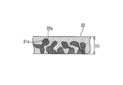
- (A)-(D) is drawing which shows the formation process of a water stop part. It is an expanded sectional view showing the state where the foamed urethane sheet was soaked with silicone.
- (A) (B) is drawing which shows 2nd embodiment.
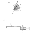
- (A) (B) is drawing which shows a shield wire. It is drawing which shows a prior art example.
- the shield wire 10 in any of the first embodiment shown in FIGS. 1 to 3 and the second embodiment shown in FIG. 4 is wired in a waterproof region of an automobile engine room, and the terminal of the shield wire 10 is connected to a connector.
- the connector is fitted in a connector housing portion of an ECU (not shown) which is disposed in the waterproof region.
- the shield wire 10 is provided with a water stop 20 at the terminal position.
- the shield wire 10 is formed by surrounding a core wire 12 made of an insulation-coated electric wire serving as two signal wires and a single drain wire 11 with a shield layer 13.
- the outer periphery of the layer 13 is covered with a sheath 14 made of an insulating coating material, and the drain wire 11 is brought into contact with the shield layer 13 to conduct.
- the drain wire 11 is made of a metal strand and does not have a coating layer.
- the shield layer 13 is formed by winding a metal foil tape. A metal wire braided tube may be used.
- the shield wire 10 cuts and peels the sheath 14 and the shield layer 13 at the peeling point P having a shortest dimension L1 of about 100 mm from the tip, and draws the drain wire 11 and the core wire 12.
- a terminal (not shown) inserted into and locked to the connector is crimped to the end of each core wire 12 and drain wire 11.
- the water stop portion 20 is provided with the water stop region S from the position of the dimension L2 (about 45 mm) in the skin peeling direction to the dimension L3 (about 45 mm) in the opposite direction across the skin peel point P of the shield wire 10. . That is, the water stop 20 is provided on the outer periphery of the drain wire 11 and the core wire 12 drawn at the position of the dimension L2, and on the outer periphery of the sheath 14 at the position of the dimension L3.
- the outer periphery of the drain wire 11 and the core wire 12 drawn out in a state where the silicone 21 used as the water stop agent is cured in a gel state (21g)
- a gel state 21g
- the outer peripheral surface of the cured silicone 21 is surrounded by a foamed urethane sheet 22 used as a foamed rubber sheet, and the outer peripheral surface of the foamed urethane sheet 22 is half-wrapped with an adhesive tape 23.
- a method for forming the water stop 20 at the end of the shielded wire 10 will be described below with reference to FIGS. 2 (A) to (D) and FIG. First, the sheath 14 and the shield layer 13 are peeled off at the end of the shield wire 10 with the dimension L1, and the core wire 12 and the drain wire 11 are pulled out from the peeled point P of the sheath 14 that has been cut.
- a foamed urethane sheet 22 cut into a rectangular shape is prepared, and the foamed urethane sheet 22 is soaked with molten sol-like silicone 21s.
- the urethane foam sheet 22 has pores 22a that are open on the surface, and is a continuous foam in which the pores 22a are three-dimensionally continuous. About%.
- the thickness (t) of the foamed urethane sheet 22 is about 2.2 mm to 2.8 mm.
- the foamed urethane sheet 22 is placed on a base (not shown), melted silicone 21 is applied to the central portion of the upper surface thereof, and silicone 21 s is filled in the pores 22 a of the foamed urethane sheet 22.
- the water stop area S of the end of the shield wire 10 is placed on the surface of the foamed urethane sheet 22 in which the molten silicone 21s is soaked into the air holes 22a.
- the sol-like silicone 21s has a viscosity of about 5 Pa.s. The fluidity is assumed to be about s.
- the urethane foam sheet 22 is wound around the water stop region S of the shield wire 10 with the application side of the silicone 21s as the inner surface.
- the adhesive tape 23 is strongly wound around the outer peripheral surface of the foamed urethane sheet 22 by half-wrapping as shown in FIG.
- the shield wire 10 including the water stop region S around which the urethane foam sheet 22 and the adhesive tape 23 are wound is held in a horizontal state and kept stationary.
- the resting time is until the silicone 21 is cured in a gel form.
- the melted silicone 21s filled in the pores 22a of the foamed urethane sheet 22 while being stationary in the horizontal state is strongly wound around the foamed urethane sheet 22 by the adhesive tape 23. Exudes from the inner surface.
- the exuded silicone 21s flows so as to adhere to the drawn core wire 12, the outer peripheral surface of the drain wire 11, the gap between the strands of the drain wire 11, the outer peripheral surface of the sheath 14, and the peeled end surface 14a of the sheath 14. To do.
- the silicone 21 is cured in a gel form, and the cured silicone 21g is the core wire 12, the outer peripheral surface of the drain wire 11, the gap between the strands of the drain wire 11, the outer peripheral surface of the sheath 14, It adheres to the peeled end surface 14a of the sheath 14 in a continuous state.
- the adhesive tape is wound around both ends.
- the cured silicone 21g can be tightly fixed from the outer peripheral surface of the sheath 14 to the peeled end surface 14a, and the silicone 21g Silicone 21g which can be tightly fixed to the outer peripheral surfaces of the drawn core wire 12 and drain wire 11 and is cured with the peel point P interposed therebetween can be made continuous.
- the outer periphery of the core wire 12 and the drain wire 11 is continuously extended from the outer peripheral surface of the sheath 14 with the peel point P of the sheath 14 interposed therebetween.
- 21 g of cured silicone is fixed. Therefore, even if a deviation occurs between the core wire 12 and the sheath 14 due to a thermal shock in which the heat changes abruptly, it is possible to prevent the separation between the silicone 21g and the sheath 14 and to prevent water stoppage. Reliability can be increased.
- the outer diameter of the water stop part 20 is enlarged. Can be suppressed.
- the shield wire 10 having the water stop portion 20 is accommodated in the corrugated tube. be able to.
- 4A and 4B show a second embodiment.
- the heat-shrinkable tube 30 of the foaming urethane sheet 22 is carried out. After covering the outer periphery, the heat shrinkable tube 30 is heated and contracted to adhere to the outer peripheral surface of the urethane foam sheet 22. When the heat-shrinkable tube 30 is contracted by heating, the heating temperature is controlled so that the contracted heat-shrinkable tube 30 strongly presses the outer peripheral surface of the foamed urethane sheet 22.
- the shield wire 10 including the water stop region S to which the foamed urethane sheet 22 and the heat shrinkable tube 30 are attached is held in a horizontal state and kept stationary. The resting time is until the silicone 21 is cured in a gel form.
- the heat shrinkable tube 30 is used instead of the adhesive tape, and the heat shrinkable tube 30 is covered with the outer peripheral surface of the foamed urethane sheet, the foamed urethane sheet is contracted by the heat shrinkable tube 30 as in the first embodiment.
- the silicone impregnated into the urethane foam sheet oozes out from the surface, and the core wire 12, the outer peripheral surface of the drain wire 11, the gap between the strands of the drain wire 11, the outer peripheral surface of the sheath 14, and the sheath 14 It flows so as to adhere to the peeled end surface 14a.
- the silicone 21 is cured in a gel state, and the cured silicone 21g is used for the core wire 12, the outer peripheral surface of the drain wire 11, the gap between the strands of the drain wire 11, the outer peripheral surface of the sheath 14, It can be fixed to the peeled end surface 14a of the sheath 14 in a continuous state.
Landscapes
- Insulated Conductors (AREA)
- Processing Of Terminals (AREA)
- Manufacturing Of Electric Cables (AREA)
- Cable Accessories (AREA)
Abstract
シールド線の端末止水部でシースと止水部との剥離発生を防止し、かつ、止水部の肥大化を抑制する。シールド線の端末のシースを皮剥してコア線とドレン線とを端末から露出させて引き出し、発泡ゴムシートに溶融した止水剤を染み込ませた防水シートを、前記シースの皮剥点を跨いでシールド線と前記露出させたコア線およびドレン線の外周に密着させて巻き付けた後、該発泡ゴムシートの外周面に粘着テープをハーフラップ巻きで強く巻き付け、または熱収縮チューブを被せた後に加熱収縮し、この状態で水平方向に保持して静止し、前記発泡ゴムシートに染み込ませた止水剤を前記粘着テープの巻き付け力で前記露出させたコア線およびドレン線の隙間に充填させると共に前記シールド線のシース内周面とコア線およびドレン線の隙間に流動させ、さらに、前記シースの外周面に止水剤を染み出させ、該状態で前記止水剤を硬化させ、前記シース端末から引き出したコア線およびドレン線の外周面から前記シースの外周面にかけて、硬化させた止水剤を連続的に固着させている。
Description
本発明は、シールド線の端末止水方法および端末止水部を備えたシールド線に関し、特に、車両のエンジンルーム等の防水領域に配線するシールド線において、該シールド線の端末からシールド線のシースとドレン線およびコア線との隙間に浸水が生じるのを防止するものである。
自動車に配索される電線のうち、特にノイズに対する遮蔽が要求される配線領域にシールド電線が用いられている。このシールド電線1としては、例えば、図5(A)に示すように、複数本の信号線となる絶縁被覆電線からなるコア線2とアース用のドレン線3とを金属箔や金属メッシュチューブ等からなるシールド層4で被覆し、該シールド層4を絶縁樹脂材料からなるシース5で順次被覆してなるものが用いられる(特開2002-208321号公報参照)。
前記ドレン線3は多数本の導電性の素線からなり、絶縁被覆がされておらず、前記シールド層4と接触させている。
前記ドレン線3は多数本の導電性の素線からなり、絶縁被覆がされておらず、前記シールド層4と接触させている。
このようなシールド電線1の端末に端子を取り付けてコネクタハウジングを接続するために、図5(B)に示すように、シールド電線1の端末で、シース5とシールド層4を約80~200mmにわたって皮剥ぎ処理し、露出したコア線2の端末を更に皮剥ぎして端子金具を圧着している。ドレン線3にも同様に端子を圧着接続し、各端子をコネクタハウジング内に挿入して、相手側機器との機械的接続を可能としている。
シールド線1では、前記シース5とシールド層4、シールド層4とコア線2およびドレン線3との間には隙間が存在し、該隙間に端末の皮剥端面から浸水が発生しやすいため、シールド線1の端末に止水部を設ける必要がある。
そのため、従来、シールド線の端末の皮剥端部で、シース5の端面からコア線2およびドレン線3の外周面にかけてペースト状のブチルゴムやシリコーンからなる止水材を取り付けて止水処理し、端末の皮剥位置からの浸水を防止している場合が多い。
そのため、従来、シールド線の端末の皮剥端部で、シース5の端面からコア線2およびドレン線3の外周面にかけてペースト状のブチルゴムやシリコーンからなる止水材を取り付けて止水処理し、端末の皮剥位置からの浸水を防止している場合が多い。
例えば、特開2007-109684号公報(特許文献2)に開示されたシールド線では、図6に示すように、シールド線1の端末皮剥位置から引き出したドレン線3にアース線7を接続し、該ドレン線3およびアース線7と、コア線2とを導電性フィラーを有するブチルゴムからなるシールド材8で被覆し、該シールド材8の外周にさらに導電性を有する外被9を巻き付け、シールド性の保持と止水とを図っている。
しかしながら、コア線2とシース5との熱収縮率の相違により端末で、コア線2よりシース5が縮みやすく、コア線2とシース5との間にズレが発生しやすい。例えば、50℃から120℃に温度を昇降させたサーマルショック試験では、シース5はコア線2より10mm縮んでいる。このコア線2とシース5とのズレにより前記ブチルゴム等からなる止水材とシース5との間に剥離が発生して隙間が生じ、該隙間からシース5の内周面側に存在する隙間に浸水が発生しやすい問題がある。
さらに、前記特許文献2のように、導電性フィラーを充填したブチルゴムからなるシールド材8を外被9でシールド線の端末剥離位置に巻き付けた構成とすると、該端末位置で外径が肥大化する問題がある。このように、シールド線の端末皮剥端で肥大化すると、シールド線を多数本有するセンサ系の回路が重なるワイヤハーネスでは、コルゲートチューブ等のチューブ類で外装する際に、該チューブ内に収まらない問題が生じる。
本発明は前記問題に鑑みてなされたもので、前記サーマルショックでシースと止水材との間に剥離が発生しないようにして止水性能を高め、かつ、止水処理部での肥大化を抑制することを課題としている。
前記課題を解決するために、第1の発明として、
シールド線の端末のシースを皮剥してコア線とドレン線とを端末から露出させて引き出し、
発泡ゴムシートに溶融した止水剤を染み込ませた防水シートを、前記シースの皮剥点を跨いで該シースの外周面と前記露出させたコア線およびドレン線の外周に密着させて巻き付けた後、
前記発泡ゴムシートの外周面に粘着テープをハーフラップ巻きで強く巻き付け、この状態で水平方向に保持して静止し、
前記発泡ゴムシートに染み込ませた止水剤を前記粘着テープの巻き付け力で前記露出させたコア線およびドレン線の隙間に充填させると共に前記シース内周面とコア線およびドレン線の隙間に流動させ、さらに、前記シースの外周面に止水剤を染み出させ、
該状態で前記止水剤を硬化させ、前記シース端末から引き出したコア線およびドレン線の外周面から前記シースの外周面および皮剥端面にかけて、硬化させた止水剤を連続的に固着させていることを特徴とするシールド線の端末止水方法を提供している。
シールド線の端末のシースを皮剥してコア線とドレン線とを端末から露出させて引き出し、
発泡ゴムシートに溶融した止水剤を染み込ませた防水シートを、前記シースの皮剥点を跨いで該シースの外周面と前記露出させたコア線およびドレン線の外周に密着させて巻き付けた後、
前記発泡ゴムシートの外周面に粘着テープをハーフラップ巻きで強く巻き付け、この状態で水平方向に保持して静止し、
前記発泡ゴムシートに染み込ませた止水剤を前記粘着テープの巻き付け力で前記露出させたコア線およびドレン線の隙間に充填させると共に前記シース内周面とコア線およびドレン線の隙間に流動させ、さらに、前記シースの外周面に止水剤を染み出させ、
該状態で前記止水剤を硬化させ、前記シース端末から引き出したコア線およびドレン線の外周面から前記シースの外周面および皮剥端面にかけて、硬化させた止水剤を連続的に固着させていることを特徴とするシールド線の端末止水方法を提供している。
前記発泡ゴムシートとして空孔率が30~70%の発泡ウレタンゴムを用い、該発泡ウレタンゴムの空孔に染み込ませる溶融した止水剤としてシリコーンを用いていることが好ましい。前記発泡ウレタンゴムの厚さは2.8~2.2mmとし、比較的薄くしている。
前記のように、本発明では、発泡ウレタンゴム等の発泡ゴムシートの空孔に溶融状態のシリコーン等の止水剤を染み込ませて充填しておき、該発泡ゴムシートを端末皮剥位置を挟んで引き出したコア線およびドレン線の外周面からシースの外周面にかけて巻き付け、さらに、発泡ゴムシートを巻き付けた直後に、該発泡ゴムシートの外周面に粘着テープをハーフラップ巻きして強く巻き付けている。これにより、発泡ゴムシートの空孔に充填している止水剤を滲み出させて、引き出したコア線およびドレン線の外周、ドレン線の素線間の隙間、さらに、シースの外周面に止水剤が塗布された状態とし、この状態で所要時間静止して止水剤を硬化している。
第2の発明として、シールド線の端末のシースを皮剥してコア線とドレン線とを端末から露出させて引き出し、
発泡ゴムシートに溶融した止水剤を染み込ませた防水シートを、前記シースの皮剥点を跨いで該シースの外周面と前記露出させたコア線およびドレン線の外周に密着させて巻き付けた後、
前記発泡ゴムシートの外周面に熱収縮チューブを被せ、
前記熱収縮チューブを加熱して収縮し、前記発泡ゴムシートの外周面に強く密着させ、この状態で水平方向に保持して静止し、
前記発泡ゴムシートに染み込ませた止水剤を前記熱収縮チューブによる収縮力で前記露出させたコア線およびドレン線の隙間に充填させると共に前記シース内周面とコア線およびドレン線の隙間に流動させ、さらに、前記シースの外周面に止水剤を染み出させ、
該状態で前記止水剤を硬化させ、前記シース端末から引き出したコア線およびドレン線の外周面から前記シースの外周面および皮剥端面にかけて、硬化させた止水剤を連続的に固着させていることを特徴とするシールド線の端末止水方法を提供している。
発泡ゴムシートに溶融した止水剤を染み込ませた防水シートを、前記シースの皮剥点を跨いで該シースの外周面と前記露出させたコア線およびドレン線の外周に密着させて巻き付けた後、
前記発泡ゴムシートの外周面に熱収縮チューブを被せ、
前記熱収縮チューブを加熱して収縮し、前記発泡ゴムシートの外周面に強く密着させ、この状態で水平方向に保持して静止し、
前記発泡ゴムシートに染み込ませた止水剤を前記熱収縮チューブによる収縮力で前記露出させたコア線およびドレン線の隙間に充填させると共に前記シース内周面とコア線およびドレン線の隙間に流動させ、さらに、前記シースの外周面に止水剤を染み出させ、
該状態で前記止水剤を硬化させ、前記シース端末から引き出したコア線およびドレン線の外周面から前記シースの外周面および皮剥端面にかけて、硬化させた止水剤を連続的に固着させていることを特徴とするシールド線の端末止水方法を提供している。
該第2の発明は、第1の発明では発泡ゴムシートの外周面を粘着テープでハーフラップ巻きで強く巻き付ける方法に代えて、熱収縮チューブを発泡ゴムシートに被せ、該熱収縮チューブを加熱して収縮し、発泡ゴムシートに強く密着させている。この熱収縮チューブの収縮率を管理して発泡ゴムシートへの加圧力を調節することで、発泡ゴムシートに染み込ませた止水剤をコア線およびドレン線の隙間に確実に充填することができる。
前記熱収縮チューブとしては住友電工ファインポリマー製の「スミチューブ」等が好適に用いられる。
前記熱収縮チューブとしては住友電工ファインポリマー製の「スミチューブ」等が好適に用いられる。
前記のように形成した端末止水部では、硬化した止水剤が引き出したコア線およびドレン線の外周面からシースの外周面にかけて連続し固着されている。よって、コア線とシースとがサーマルショックでシースが縮んでズレが発生しても、シースの外周面に硬化した止水剤が引き出したコア線の外周面から連続して設けられているため、止水剤とシースの皮剥端面との間に剥離が発生するのを防止できる。その結果、剥離箇所から浸水が生じるのを防止でき、止水性能を保持できる。
また、発泡ゴムシートを粘着テープで強くハーフラップ巻きするため、または熱収縮チューブで強く加圧するため、発泡ゴムシートを薄肉化でき、その外径を肥大化させない。よって、例えば、特許文献2に記載のブチルゴムおよび外皮を被覆した場合と比較して30%程度小径化することができる。このように、シールド線の端末止水部の肥大化を抑制できるため、複数本のシールド線が集束されたワイヤハーネスをコルゲートチューブ内に収容することができる。
また、発泡ゴムシートを粘着テープで強くハーフラップ巻きするため、または熱収縮チューブで強く加圧するため、発泡ゴムシートを薄肉化でき、その外径を肥大化させない。よって、例えば、特許文献2に記載のブチルゴムおよび外皮を被覆した場合と比較して30%程度小径化することができる。このように、シールド線の端末止水部の肥大化を抑制できるため、複数本のシールド線が集束されたワイヤハーネスをコルゲートチューブ内に収容することができる。
本発明は前記方法で形成された端末止水部を備えたシールド線を提供している。
前記シールド線は、自動車のエンジンルームを含む被水領域に好適に配索される。
被水領域に配線されたシールド線は、ドレン線の端末に端子が接続され、該シールド線の端末から引き出されるコア線端末に接続された端子と共に、前記被水領域に配置される機器に接続される。
例えば、ドレン線端末の端子を、他のコア線の端末に接続された端子と共に防水コネクタに挿入係止し、該防水コネクタをエンジンルームに搭載されるECUのコネクタ嵌合部等に嵌合している。
前記シールド線は、自動車のエンジンルームを含む被水領域に好適に配索される。
被水領域に配線されたシールド線は、ドレン線の端末に端子が接続され、該シールド線の端末から引き出されるコア線端末に接続された端子と共に、前記被水領域に配置される機器に接続される。
例えば、ドレン線端末の端子を、他のコア線の端末に接続された端子と共に防水コネクタに挿入係止し、該防水コネクタをエンジンルームに搭載されるECUのコネクタ嵌合部等に嵌合している。
上述したように、本発明のシールド線の端末止水部では、シースの皮剥点を挟んで、引き出したコア線およびドレン線の外周面からシースの外周面にかけて連続的に硬化させた止水剤を固着している。よって、熱が急激に変化するサーマルショックでコア線とシースとの間にズレが発生しても、止水剤とシースとの間に剥離が発生するのを防止でき、止水性能の信頼性を高めることができる。
かつ、端末止水部では、発泡ゴムシートの外周面に粘着テープを強くハーフラップ巻きして、または熱収縮チューブを被せた後に加熱して熱収縮チューブを収縮させ、発泡ゴムシートを外周から加圧して薄肉化を図っているため、端末止水部での外径の肥大化を抑制することができる。
かつ、端末止水部では、発泡ゴムシートの外周面に粘着テープを強くハーフラップ巻きして、または熱収縮チューブを被せた後に加熱して熱収縮チューブを収縮させ、発泡ゴムシートを外周から加圧して薄肉化を図っているため、端末止水部での外径の肥大化を抑制することができる。
以下、本発明の実施形態を図面を参照して説明する。
図1から図3の第一実施形態、図4の第二実施形態のいずれの実施形態のシールド線10は自動車のエンジンルームの防水領域に配線され、該シールド線10の端末をコネクタに接続し、該コネクタを防水領域に配置するECU(図示せず)のコネクタ収容部に嵌合している。前記シールド線10には端末位置に止水部20を設けている。
図1から図3の第一実施形態、図4の第二実施形態のいずれの実施形態のシールド線10は自動車のエンジンルームの防水領域に配線され、該シールド線10の端末をコネクタに接続し、該コネクタを防水領域に配置するECU(図示せず)のコネクタ収容部に嵌合している。前記シールド線10には端末位置に止水部20を設けている。
図1に示すように、シールド線10は、本実施形態では、2本の信号線となる絶縁被覆電線からなるコア線12と1本のドレン線11とを、シールド層13で囲み、該シールド層13の外周を絶縁被覆材からなるシース14で被覆し、シールド層13にドレン線11を接触させて導通している。
前記ドレン線11は金属素線からなり、被覆層は備えていない。また、シールド層13は金属箔テープを巻き付けて形成している。なお、金属線の編チューブでもよい。
前記ドレン線11は金属素線からなり、被覆層は備えていない。また、シールド層13は金属箔テープを巻き付けて形成している。なお、金属線の編チューブでもよい。
前記シールド線10は、先端から100mm程度の最短寸法L1の皮剥点Pでシース14およびシールド層13を切断剥離してドレン線11とコア線12とを引き出している。各コア線12およびドレン線11の端末にコネクタに挿入係止される端子(図示せず)が圧着接続される。
前記シールド線10の皮剥点Pを挟んで、皮剥方向に寸法L2(約45mm)の位置から反対方向に寸法L3(約45mm)までを止水領域Sとして、前記止水部20を設けている。
即ち、前記寸法L2の位置では引き出したドレン線11、コア線12の外周、前記寸法L3の位置ではシース14の外周に止水部20を設けている。
即ち、前記寸法L2の位置では引き出したドレン線11、コア線12の外周、前記寸法L3の位置ではシース14の外周に止水部20を設けている。
前記止水部20では、図1(C)(D)に示すように、止水剤とするシリコーン21がゲル状(21g)に硬化された状態で引き出したドレン線11およびコア線12の外周からシース14の外周、さらに、シース14の皮剥端面14aに連続した状態で固着している。該硬化したシリコーン21の外周面を発泡ゴムシートとして用いる発泡ウレタンシート22で囲み、該発泡ウレタンシート22の外周面を粘着テープ23でハーフラップ巻きしている。
前記シールド線10の端末の止水部20の形成方法を、図2(A)~(D)および図3を参照して、以下に説明する。
まず、シールド線10の端末でシース14およびシールド層13を前記寸法L1で剥離して、コア線12とドレン線11とを切断されたシース14の皮剥点Pより引き出す。
まず、シールド線10の端末でシース14およびシールド層13を前記寸法L1で剥離して、コア線12とドレン線11とを切断されたシース14の皮剥点Pより引き出す。
図2(A)に示すように、長方形状に切断された発泡ウレタンシート22を用意し、該発泡ウレタンシート22に溶融したゾル状のシリコーン21sを染み込ませている。
具体的には、図3に示すように、発泡ウレタンシート22は表面に開口した空孔22aを備え、該空孔22aを三次元状に連続させた連続発泡体とし、空孔率は約50%程度としている。該発泡ウレタンシート22の厚さ(t)は2.2mm~2.8mm程度としている。
該発泡ウレタンシート22を基台(図示せず)に載置し、その上面の中央部に溶融したシリコーン21を塗布して、シリコーン21sを発泡ウレタンシート22の空孔22aに充填している。
具体的には、図3に示すように、発泡ウレタンシート22は表面に開口した空孔22aを備え、該空孔22aを三次元状に連続させた連続発泡体とし、空孔率は約50%程度としている。該発泡ウレタンシート22の厚さ(t)は2.2mm~2.8mm程度としている。
該発泡ウレタンシート22を基台(図示せず)に載置し、その上面の中央部に溶融したシリコーン21を塗布して、シリコーン21sを発泡ウレタンシート22の空孔22aに充填している。
前記溶融したシリコーン21sを空孔22aに染み込ませている発泡ウレタンシート22の表面に図2(B)に示すように、前記シールド線10の端末の止水領域Sを載置する。
前記ゾル状のシリコーン21sの粘度は約5Pa.s程度として流動性を持たせているものとしている。
前記ゾル状のシリコーン21sの粘度は約5Pa.s程度として流動性を持たせているものとしている。
ついで、図2(C)に示すように、発泡ウレタンシート22をシリコーン21sの塗布側を内面としてシールド線10の止水領域Sに巻き付ける。
該発泡ウレタンシート22の巻き付け直後でシリコーン21の硬化前に、図2(D)に示すように、粘着テープ23を発泡ウレタンシート22の外周面にハーフラップ巻きで強く巻き付ける。
該発泡ウレタンシート22の巻き付け直後でシリコーン21の硬化前に、図2(D)に示すように、粘着テープ23を発泡ウレタンシート22の外周面にハーフラップ巻きで強く巻き付ける。
この状態で、発泡ウレタンシート22および粘着テープ23を巻き付けた止水領域Sを含むシールド線10を水平状態に保持して静止しておく。該静止時間はシリコーン21がゲル状に硬化するまでである。
前記水平状態で静止している間、発泡ウレタンシート22の空孔22a内に充填している溶融したシリコーン21sは、粘着テープ23により発泡ウレタンシート22が強く巻き付けられることにより、発泡ウレタンシート22の内周面より染み出す。染み出したシリコーン21sは引き出されたコア線12、ドレン線11の外周面、ドレン線11の素線間の隙間、シース14の外周面、さらに、シース14の皮剥端面14aに付着するように流動する。
所要時間経過後にシリコーン21はゲル状に硬化され、該硬化したシリコーン21gが、前記コア線12、ドレン線11の外周面、ドレン線11の素線間の隙間、シース14の外周面、さらに、シース14の皮剥端面14aに連続した状態で固着する。
所要時間経過後にシリコーン21はゲル状に硬化され、該硬化したシリコーン21gが、前記コア線12、ドレン線11の外周面、ドレン線11の素線間の隙間、シース14の外周面、さらに、シース14の皮剥端面14aに連続した状態で固着する。
前記のように、シリコーン21gが硬化した後、シリコーン21が発泡ウレタンシート22および粘着テープ23の長さ方向両端からはみ出している場合は、両端に粘着テープを巻き付けている。
このように、シールド線10の端末に止水部20を形成しているため、前記のように硬化したシリコーン21gをシース14の外周面から皮剥端面14aに密に固着できるとともに、該シリコーン21gを引き出したコア線12およびドレン線11の外周面に密に固着でき、かつ、皮剥点Pを挟んで硬化したシリコーン21gを連続させることができる。
前記のように、シールド線10の端末に設けた止水部20では、シース14の皮剥点Pを挟んで、引き出したコア線12およびドレン線11の外周面からシース14の外周面にかけて連続的に硬化させたシリコーン21gが固着している。よって、熱が急激に変化するサーマルショックでコア線12とシース14との間にズレが発生しても、シリコーン21gとシース14との間に剥離が発生するのを防止でき、止水性能の信頼性を高めることができる。
かつ、止水部20では、発泡ウレタンシート22の外周面に粘着テープ23を強くハーフラップ巻きして、発泡ウレタンシート22の薄肉化を図っているため、止水部20での外径の肥大化を抑制することができる。その結果、端末に止水部20を備えたシールド線10が複数本集束されたワイヤハーネスにコルゲートチューブを外装しても、該コルゲートチューブ内に止水部20を備えたシールド線10を収容することができる。
かつ、止水部20では、発泡ウレタンシート22の外周面に粘着テープ23を強くハーフラップ巻きして、発泡ウレタンシート22の薄肉化を図っているため、止水部20での外径の肥大化を抑制することができる。その結果、端末に止水部20を備えたシールド線10が複数本集束されたワイヤハーネスにコルゲートチューブを外装しても、該コルゲートチューブ内に止水部20を備えたシールド線10を収容することができる。
図4(A)(B)に第二実施形態を示す。
第二実施形態では、止水剤となるシリコーン21を塗布した発泡ウレタンシート22をシールド線10の止水領域Sに巻き付けた後、シリコーンが硬化する前に熱収縮チューブ30を発泡ウレタンシート22の外周に被せ、その後、熱収縮チューブ30を加熱して収縮し、発泡ウレタンシート22の外周面に密着させている。
熱収縮チューブ30を加熱して収縮する際に、加熱温度を管理して、収縮した熱収縮チューブ30が発泡ウレタンシート22の外周面を強く加圧する程度に収縮させている。
第二実施形態では、止水剤となるシリコーン21を塗布した発泡ウレタンシート22をシールド線10の止水領域Sに巻き付けた後、シリコーンが硬化する前に熱収縮チューブ30を発泡ウレタンシート22の外周に被せ、その後、熱収縮チューブ30を加熱して収縮し、発泡ウレタンシート22の外周面に密着させている。
熱収縮チューブ30を加熱して収縮する際に、加熱温度を管理して、収縮した熱収縮チューブ30が発泡ウレタンシート22の外周面を強く加圧する程度に収縮させている。
熱収縮チューブ30を収縮させた後、発泡ウレタンシート22および熱収縮チューブ30を取り付けた止水領域Sを含むシールド線10を水平状態に保持して静止しておく。該静止時間はシリコーン21がゲル状に硬化するまでである。
粘着テープに代えて熱収縮チューブ30を用いて、発泡ウレタンシートの外周面に被せた後に熱収縮させた場合も、第一実施形態と同様に、熱収縮チューブ30により収縮力で発泡ウレタンシートを圧縮することにより、該発泡ウレタンシートに含浸したシリコーンを表面より染みだし、コア線12、ドレン線11の外周面、ドレン線11の素線間の隙間、シース14の外周面、さらに、シース14の皮剥端面14aに付着するように流動する。
所要時間経過後、シリコーン21はゲル状に硬化され、該硬化したシリコーン21gが、前記コア線12、ドレン線11の外周面、ドレン線11の素線間の隙間、シース14の外周面、さらに、シース14の皮剥端面14aに連続した状態で固着させることができる。
粘着テープに代えて熱収縮チューブ30を用いて、発泡ウレタンシートの外周面に被せた後に熱収縮させた場合も、第一実施形態と同様に、熱収縮チューブ30により収縮力で発泡ウレタンシートを圧縮することにより、該発泡ウレタンシートに含浸したシリコーンを表面より染みだし、コア線12、ドレン線11の外周面、ドレン線11の素線間の隙間、シース14の外周面、さらに、シース14の皮剥端面14aに付着するように流動する。
所要時間経過後、シリコーン21はゲル状に硬化され、該硬化したシリコーン21gが、前記コア線12、ドレン線11の外周面、ドレン線11の素線間の隙間、シース14の外周面、さらに、シース14の皮剥端面14aに連続した状態で固着させることができる。
このように、粘着テープによるハーフラップ巻きに代えて熱収縮チューブを用いると、熟練度に依存するテープ巻きよりも、均一な力を発泡ウレタンシートに加えることができ、作業性が良くなる利点がある。
10 シールド線
11 ドレン線
12 コア線
13 シールド層
14 シース
20 止水部
21 シリコーン
21s ゾル状とした流動性を有するシリコーン
21g ゲル状に硬化させたシリコーン
22 発泡ウレタンシート
23 粘着テープ
30 熱収縮チューブ
P 皮剥点
S 止水領域
11 ドレン線
12 コア線
13 シールド層
14 シース
20 止水部
21 シリコーン
21s ゾル状とした流動性を有するシリコーン
21g ゲル状に硬化させたシリコーン
22 発泡ウレタンシート
23 粘着テープ
30 熱収縮チューブ
P 皮剥点
S 止水領域
Claims (5)
- シールド線の端末のシースを皮剥してコア線とドレン線とを端末から露出させて引き出し、
発泡ゴムシートに溶融した止水剤を染み込ませた防水シートを、前記シースの皮剥点を跨いで該シースの外周面と前記露出させたコア線およびドレン線の外周に密着させて巻き付けた後、
前記発泡ゴムシートの外周面に粘着テープをハーフラップ巻きで強く巻き付け、この状態で水平方向に保持して静止し、
前記発泡ゴムシートに染み込ませた止水剤を前記粘着テープの巻き付け力で前記露出させたコア線およびドレン線の隙間に充填させると共に前記シース内周面とコア線およびドレン線の隙間に流動させ、さらに、前記シースの外周面に止水剤を染み出させ、
該状態で前記止水剤を硬化させ、前記シース端末から引き出したコア線およびドレン線の外周面から前記シースの外周面および皮剥端面にかけて、硬化させた止水剤を連続的に固着させていることを特徴とするシールド線の端末止水方法。 - シールド線の端末のシースを皮剥してコア線とドレン線とを端末から露出させて引き出し、
発泡ゴムシートに溶融した止水剤を染み込ませた防水シートを、前記シースの皮剥点を跨いで該シースの外周面と前記露出させたコア線およびドレン線の外周に密着させて巻き付けた後、
前記発泡ゴムシートの外周面に熱収縮チューブを被せ、
前記熱収縮チューブを加熱して収縮し、前記発泡ゴムシートの外周面に強く密着させ、この状態で水平方向に保持して静止し、
前記発泡ゴムシートに染み込ませた止水剤を前記熱収縮チューブによる収縮力で前記露出させたコア線およびドレン線の隙間に充填させると共に前記シース内周面とコア線およびドレン線の隙間に流動させ、さらに、前記シースの外周面に止水剤を染み出させ、
該状態で前記止水剤を硬化させ、前記シース端末から引き出したコア線およびドレン線の外周面から前記シースの外周面および皮剥端面にかけて、硬化させた止水剤を連続的に固着させていることを特徴とするシールド線の端末止水方法。 - 前記発泡ゴムシートとして空孔率が30~70%の発泡ウレタンゴムを用い、該発泡ウレタンゴムの空孔に染み込ませる溶融した止水剤としてシリコーンを用いている請求項1または請求項2に記載のシールド線の端末止水方法。
- 請求項1または請求項2に記載の方法で形成された端末止水部を備えたシールド線。
- 自動車のエンジンルームを含む被水領域に配索される請求項4に記載の端末止水部を備えたシールド線。
Applications Claiming Priority (4)
| Application Number | Priority Date | Filing Date | Title |
|---|---|---|---|
| JP2008299809 | 2008-11-25 | ||
| JP2008-299809 | 2008-11-25 | ||
| JP2009030169A JP5287322B2 (ja) | 2008-11-25 | 2009-02-12 | シールド線の端末止水方法および端末止水部を備えたシールド線 |
| JP2009-030169 | 2009-02-12 |
Publications (1)
| Publication Number | Publication Date |
|---|---|
| WO2010061748A1 true WO2010061748A1 (ja) | 2010-06-03 |
Family
ID=42225626
Family Applications (1)
| Application Number | Title | Priority Date | Filing Date |
|---|---|---|---|
| PCT/JP2009/069436 Ceased WO2010061748A1 (ja) | 2008-11-25 | 2009-11-16 | シールド線の端末止水方法および端末止水部を備えたシールド線 |
Country Status (2)
| Country | Link |
|---|---|
| JP (1) | JP5287322B2 (ja) |
| WO (1) | WO2010061748A1 (ja) |
Cited By (4)
| Publication number | Priority date | Publication date | Assignee | Title |
|---|---|---|---|---|
| JP2010192309A (ja) * | 2009-02-19 | 2010-09-02 | Sumitomo Wiring Syst Ltd | シールド線の端末止水方法および端末止水部を備えたシールド線 |
| CN103928150A (zh) * | 2014-04-26 | 2014-07-16 | 芜湖航天特种电缆厂 | 耐水性控制电缆 |
| CN114743740A (zh) * | 2022-04-01 | 2022-07-12 | 江苏南瑞银龙电缆有限公司 | 一种特高压电缆的制造装置 |
| CN117174388A (zh) * | 2023-09-14 | 2023-12-05 | 上海赢双电机科技股份有限公司 | 密封式线束及其制备方法 |
Families Citing this family (7)
| Publication number | Priority date | Publication date | Assignee | Title |
|---|---|---|---|---|
| JP5581929B2 (ja) * | 2010-09-15 | 2014-09-03 | 住友電装株式会社 | ワイヤハーネスの防水構造 |
| JP5418457B2 (ja) | 2010-09-30 | 2014-02-19 | 住友電装株式会社 | 電線の止水中間スプライス部の製造方法及び電線の止水中間スプライス部 |
| JP2012126356A (ja) * | 2010-12-17 | 2012-07-05 | Yazaki Corp | ワイヤハーネス |
| JP6079292B2 (ja) * | 2013-02-21 | 2017-02-15 | 住友電装株式会社 | ワイヤーハーネス |
| CN103956206A (zh) * | 2014-03-28 | 2014-07-30 | 安徽长风电缆集团有限公司 | 一种防静电耐高温电缆 |
| JP6210971B2 (ja) * | 2014-12-26 | 2017-10-11 | 矢崎総業株式会社 | 止水構造及びワイヤハーネス |
| CN104681170A (zh) * | 2015-01-31 | 2015-06-03 | 安徽华泰电缆科技有限公司 | 一种防静电电缆 |
Citations (3)
| Publication number | Priority date | Publication date | Assignee | Title |
|---|---|---|---|---|
| WO2007072885A1 (ja) * | 2005-12-21 | 2007-06-28 | Sekisui Chemical Co., Ltd. | 独立気泡発泡ゴムシート、積層体及びそれらを用いた止水・水密シール材 |
| JP2008016301A (ja) * | 2006-07-05 | 2008-01-24 | Auto Network Gijutsu Kenkyusho:Kk | シールド線のドレン線止水方法およびドレン線止水構造 |
| JP2008108684A (ja) * | 2006-02-02 | 2008-05-08 | Auto Network Gijutsu Kenkyusho:Kk | シールド線のドレン線止水構造およびドレン線止水方法 |
-
2009
- 2009-02-12 JP JP2009030169A patent/JP5287322B2/ja not_active Expired - Fee Related
- 2009-11-16 WO PCT/JP2009/069436 patent/WO2010061748A1/ja not_active Ceased
Patent Citations (3)
| Publication number | Priority date | Publication date | Assignee | Title |
|---|---|---|---|---|
| WO2007072885A1 (ja) * | 2005-12-21 | 2007-06-28 | Sekisui Chemical Co., Ltd. | 独立気泡発泡ゴムシート、積層体及びそれらを用いた止水・水密シール材 |
| JP2008108684A (ja) * | 2006-02-02 | 2008-05-08 | Auto Network Gijutsu Kenkyusho:Kk | シールド線のドレン線止水構造およびドレン線止水方法 |
| JP2008016301A (ja) * | 2006-07-05 | 2008-01-24 | Auto Network Gijutsu Kenkyusho:Kk | シールド線のドレン線止水方法およびドレン線止水構造 |
Cited By (4)
| Publication number | Priority date | Publication date | Assignee | Title |
|---|---|---|---|---|
| JP2010192309A (ja) * | 2009-02-19 | 2010-09-02 | Sumitomo Wiring Syst Ltd | シールド線の端末止水方法および端末止水部を備えたシールド線 |
| CN103928150A (zh) * | 2014-04-26 | 2014-07-16 | 芜湖航天特种电缆厂 | 耐水性控制电缆 |
| CN114743740A (zh) * | 2022-04-01 | 2022-07-12 | 江苏南瑞银龙电缆有限公司 | 一种特高压电缆的制造装置 |
| CN117174388A (zh) * | 2023-09-14 | 2023-12-05 | 上海赢双电机科技股份有限公司 | 密封式线束及其制备方法 |
Also Published As
| Publication number | Publication date |
|---|---|
| JP2010153344A (ja) | 2010-07-08 |
| JP5287322B2 (ja) | 2013-09-11 |
Similar Documents
| Publication | Publication Date | Title |
|---|---|---|
| JP5287322B2 (ja) | シールド線の端末止水方法および端末止水部を備えたシールド線 | |
| JP4950531B2 (ja) | シールド電線の止水構造および止水方法 | |
| JP5541901B2 (ja) | 止水処理方法および絶縁被覆電線 | |
| JP5188713B2 (ja) | ドレン線止水構造を備えたシールド線およびドレン線止水方法 | |
| JP2584507Y2 (ja) | 電線の防水構造 | |
| JP5117008B2 (ja) | 電線芯線の止水処理構造及び電線芯線の止水処理方法 | |
| JP2016163509A (ja) | ワイヤハーネスの防水構造 | |
| JP2009152012A (ja) | 電線の止水方法及び該止水方法で形成された止水部を有する電線 | |
| JP2008204644A (ja) | 防水ハーネスの製造方法、ハーネス用防水剤、および防水ハーネス | |
| JP5402065B2 (ja) | シールド線の端末止水方法および端末止水部を備えたシールド線 | |
| JP2011065964A (ja) | 止水部を備えたシールド電線および該シールド電線の止水部の形成方法 | |
| JP5304405B2 (ja) | シールド線端末の止水構造 | |
| JP4767137B2 (ja) | シールド線の止水方法および止水構造 | |
| JP2012204016A (ja) | 電線の止水方法および電線の止水構造 | |
| JP2008234974A (ja) | シールド線のドレン線止水方法およびドレン線止水構造 | |
| JP5391613B2 (ja) | シールド線の止水方法 | |
| JP2008305634A (ja) | シールド線のドレン線止水構造 | |
| JP5144319B2 (ja) | シールド電線におけるドレーン線とアース線とのジョイント部の止水構造及び止水方法 | |
| JP5304406B2 (ja) | シールド線端末の止水構造および該止水構造の形成方法 | |
| JP2020036472A (ja) | 電線束の止水方法 | |
| JP4928178B2 (ja) | シールド線のドレン線止水方法およびドレン線止水構造 | |
| JP2011065924A (ja) | シールド電線の止水部の形成方法および止水部を備えたシールド電線 | |
| JP2011065911A (ja) | 止水部を備えたシールド電線および該シールド電線の止水部の形成方法 | |
| JP2010129241A (ja) | シールド線の端末止水構造 | |
| JP2010129229A (ja) | シールド線の止水方法および止水部を備えたシールド線 |
Legal Events
| Date | Code | Title | Description |
|---|---|---|---|
| 121 | Ep: the epo has been informed by wipo that ep was designated in this application |
Ref document number: 09828996 Country of ref document: EP Kind code of ref document: A1 |
|
| NENP | Non-entry into the national phase |
Ref country code: DE |
|
| 122 | Ep: pct application non-entry in european phase |
Ref document number: 09828996 Country of ref document: EP Kind code of ref document: A1 |