WO2010049987A1 - Transfer shuttle for automated warehouse - Google Patents
Transfer shuttle for automated warehouse Download PDFInfo
- Publication number
- WO2010049987A1 WO2010049987A1 PCT/JP2008/069464 JP2008069464W WO2010049987A1 WO 2010049987 A1 WO2010049987 A1 WO 2010049987A1 JP 2008069464 W JP2008069464 W JP 2008069464W WO 2010049987 A1 WO2010049987 A1 WO 2010049987A1
- Authority
- WO
- WIPO (PCT)
- Prior art keywords
- load
- rail
- transfer shuttle
- slide rail
- finger
- Prior art date
Links
- 230000007246 mechanism Effects 0.000 claims abstract description 37
- 230000002093 peripheral effect Effects 0.000 claims description 4
- 230000008602 contraction Effects 0.000 description 13
- 230000000694 effects Effects 0.000 description 2
- 238000004519 manufacturing process Methods 0.000 description 2
- 229910000831 Steel Inorganic materials 0.000 description 1
- 230000004308 accommodation Effects 0.000 description 1
- 230000002411 adverse Effects 0.000 description 1
- 238000010586 diagram Methods 0.000 description 1
- 238000006073 displacement reaction Methods 0.000 description 1
- 230000001788 irregular Effects 0.000 description 1
- 238000000034 method Methods 0.000 description 1
- 238000012986 modification Methods 0.000 description 1
- 230000004048 modification Effects 0.000 description 1
- 239000010959 steel Substances 0.000 description 1
Images


Classifications
-
- B—PERFORMING OPERATIONS; TRANSPORTING
- B65—CONVEYING; PACKING; STORING; HANDLING THIN OR FILAMENTARY MATERIAL
- B65G—TRANSPORT OR STORAGE DEVICES, e.g. CONVEYORS FOR LOADING OR TIPPING, SHOP CONVEYOR SYSTEMS OR PNEUMATIC TUBE CONVEYORS
- B65G1/00—Storing articles, individually or in orderly arrangement, in warehouses or magazines
- B65G1/02—Storage devices
- B65G1/04—Storage devices mechanical
- B65G1/0407—Storage devices mechanical using stacker cranes
- B65G1/0435—Storage devices mechanical using stacker cranes with pulling or pushing means on either stacking crane or stacking area
-
- B—PERFORMING OPERATIONS; TRANSPORTING
- B65—CONVEYING; PACKING; STORING; HANDLING THIN OR FILAMENTARY MATERIAL
- B65G—TRANSPORT OR STORAGE DEVICES, e.g. CONVEYORS FOR LOADING OR TIPPING, SHOP CONVEYOR SYSTEMS OR PNEUMATIC TUBE CONVEYORS
- B65G1/00—Storing articles, individually or in orderly arrangement, in warehouses or magazines
- B65G1/02—Storage devices
- B65G1/04—Storage devices mechanical
- B65G1/12—Storage devices mechanical with separate article supports or holders movable in a closed circuit to facilitate insertion or removal of articles the articles being books, documents, forms or the like
-
- B—PERFORMING OPERATIONS; TRANSPORTING
- B65—CONVEYING; PACKING; STORING; HANDLING THIN OR FILAMENTARY MATERIAL
- B65G—TRANSPORT OR STORAGE DEVICES, e.g. CONVEYORS FOR LOADING OR TIPPING, SHOP CONVEYOR SYSTEMS OR PNEUMATIC TUBE CONVEYORS
- B65G1/00—Storing articles, individually or in orderly arrangement, in warehouses or magazines
- B65G1/02—Storage devices
- B65G1/04—Storage devices mechanical
- B65G1/0492—Storage devices mechanical with cars adapted to travel in storage aisles
Definitions
- the present invention relates to a three-dimensional automatic warehouse including at least one pair of stacked racks arranged in parallel to each other, and particularly in a horizontal direction, arranged at every level or every several levels between a pair of stacked racks.
- the present invention relates to a transfer shuttle that travels to and from a stacked rack.
- the three-dimensional automatic warehouse described in this publication includes at least a pair of left and right stacked racks composed of a plurality of shelves. Between the stacked racks, a transfer shuttle that can travel in the horizontal direction is provided for each stage.
- the transfer shuttle is for loading and unloading the left and right stacking racks.
- a conventional transfer shuttle generally has a traveling cart that can place a load in the center, and a picking mechanism that loads and removes the load on this traveling cart in a horizontal and horizontal direction (both left and right) perpendicular to the traveling direction. And.
- the conventional picking mechanism described in Japanese Patent Application Laid-Open No. H8-324721 is composed of a three-stage expansion / contraction mechanism provided respectively before and after a load placement area for loading a load on a traveling carriage.
- the telescopic mechanism is a well-known mechanism, and is a fixed rail fixed to the traveling carriage, a first sliding rail slidably attached to the fixed rail, and slidable on the first sliding rail.
- the second slide rail is attached to the second slide rail.
- the first slide rail and the second slide rail are connected by a pulley and a belt.
- the first slide rail driving means includes a motor attached to the traveling carriage, a pinion attached to the rotating shaft of the motor, and a rack fixed to the first slide rail meshing with the pinion. It consists of and.
- both end portions of the second slide rail are provided with end fingers that operate between a protruding position protruding toward the loading area and a retracted position retracted from the loading area.
- An object of the present invention is to solve the conventional problems as described above, and to provide a transfer shuttle that can place a larger number of loads on each shelf of a stacked rack.
- the transfer shuttle according to the present invention is for delivering a load to a stacked rack used in a three-dimensional automatic warehouse including a pair of stacked racks arranged in parallel to each other.
- the transfer shuttle travels in the horizontal direction between the stacked racks, and has a traveling carriage having a loading area for placing a load, and the loading area in the traveling direction of the traveling carriage.
- a telescopic mechanism provided on each of the front side portion and the rear side portion and configured to extend and contract in a horizontal and transverse direction perpendicular to the traveling direction, and the most movable range of the plurality of rails.
- the large rail It is provided at each of both ends of the large rail, and has an end finger operable between a protruding position protruding toward the loading area and a retracted position retracted from the loading area.
- move between a protrusion position and a retracted position is provided in the rail which becomes the load mounting area side between edge part fingers.
- the load on the loading area of the transfer shuttle can be pushed out by the inner finger.
- the load is pushed out by the end fingers of the rail, but in the present invention, the load is pushed out by the inner fingers and the overlap between the rails is minimized, so that the stacking rack is deeper. It becomes possible to carry the load to the point. As a result, a larger number of loads can be accommodated in the stacked rack. More specifically, even with the same three-stage expansion / contraction mechanism as before, two loads can be arranged side by side (in two rows in the front and rear direction) in the expansion / contraction direction.
- Each of the telescopic mechanisms is fixed to the traveling carriage and extends in a horizontal lateral direction perpendicular to the traveling direction, and a first rail slidably attached to the fixed rail in parallel to the horizontal lateral direction. Slidably attached to the first slide rail in parallel with the horizontal lateral direction, and in conjunction with the first slide rail, the same movement direction as the first slide rail is provided. A second slide rail moving in the direction, in which case the end finger and the inner finger are provided on the second slide rail.
- the driving means of the first slide rail includes an endless belt having teeth on the outer peripheral surface disposed on the traveling carriage along the fixed rail, and an outer periphery of the belt. It is preferable to include a rack provided on the first slide rail that meshes with the teeth of the surface.
- the first sliding rail can be more protruded from the fixed rail.
- the protruding amount of the slide rail is greatly limited.
- the use of a belt with external teeth eliminates such an adverse effect.
- the number of inner fingers can be one. In this configuration, two loads can be handled simultaneously.
- FIG. 1 is a partial perspective view showing a three-dimensional automatic warehouse in which a transfer shuttle according to the present invention is used.
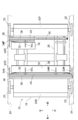
- FIG. 2 is a side view of a transfer shuttle according to the present invention.
- FIG. 3 is a plan view showing the transfer chart according to the present invention with a part cut away.
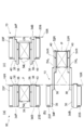
- FIG. 4 is a schematic view showing the operation of the transfer shuttle according to the present invention.
- FIG. 5 is a schematic view showing the principle of the telescopic mechanism in the transfer shuttle according to the present invention.
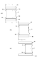
- FIG. 6 is a schematic view showing a main part of the transfer shuttle according to the present invention.
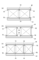
- FIG. 7 is a diagram showing several modified examples of the transfer shuttle of the present invention.
- FIG. 1 is a perspective view showing a part of a three-dimensional automatic warehouse 12 in which a transfer shuttle 10 according to the present invention is used.
- the illustrated three-dimensional automatic warehouse 12 includes at least a pair of left and right stacked racks 16L and 16R composed of a plurality of shelves 14. Between the stacked racks 16L and 16R, the transfer shuttle 10 according to the present invention for delivering the load P between the stacked racks 16L and 16R is provided for each stage or for each of a plurality of stages.
- the stacked racks 16L and 16R are configured to accommodate a shaped product, such as a bucket (plastic return box), as the load P.
- the depth of the shelf 14 in the stacked racks 16L and 16R (the length in the left-right direction shown in FIG. 1) is twice that of the conventional rack. Can be placed side by side.
- one end or both ends of the left and right stacked racks 16L and 16R are moved to transfer loads between the stacked racks 16L and 16R and an external transfer system.
- the cargo is delivered between the stacking racks 16L and 16R via the loading shuttle 10, and the transit station where the cargo is temporarily waited as necessary, and between the transit station and the external transport system.
- a lifting device for delivering the load is provided.
- the transfer shuttle 10 As shown in FIGS. 2 and 3, the transfer shuttle 10 according to the present invention used in the three-dimensional automatic warehouse 12 as described above has a traveling carriage 18 that travels horizontally between the left and right stacked racks 16L and 16R.
- Chassis portions 20F and 20B for accommodating a drive motor, a power source / control unit and the like (not shown) are provided in the front portion and the rear portion of the traveling carriage 18 along the traveling direction, respectively.
- a traveling wheel 22 is provided on each of the left and right sides of the chassis portions 20F and 20B.
- the traveling wheel 22 is disposed on a guide rail 24 extending in the horizontal direction provided at each stage of the left and right stacked racks 16L and 16R. Placed. Therefore, the traveling carriage 18 can travel back and forth along the guide rail 24 by rotating at least one of the traveling wheels 22 by the drive motor inside the chassis portion 20F or 20B.
- a load placement area 26 on which the load P is placed. More specifically, a base frame 28 is provided between the lower portions of the front and rear chassis portions 20F and 20B, and a load placement area 26 is provided by a pair of load placement plates 30 placed horizontally on the base frame 28. The bottom of is defined. Side guides 32 are formed on the outer edge of each loading plate 30 (on the side close to the adjacent chassis portions 20F and 20B), and the width between the side guides 32 is slightly larger than the width of the load P. Has been. As a result, the load P can be moved in the horizontal direction on the load placement plate 30 without causing lateral displacement or rotation. Moreover, the length (the dimension in the left-right lateral direction) of the load placement area 26 is set to a length sufficient to receive a normal load P to be handled.
- the front and rear chassis portions 20F and 20B of the traveling carriage 18 are provided with a pair of front and rear extension mechanisms 34F and 34B for loading and unloading the load P with the load placement area 26 interposed therebetween.
- the expansion / contraction mechanisms 34F and 34B are driven synchronously and used to deliver the load P between the load placement area 26 and the racks 14 of the stacked racks 16L and 16R.
- the telescopic mechanisms 34F and 34B are fixed to the inward surfaces (surfaces facing the load placement area 26) of the chassis portions 20F and 20B, and are fixed to extend in the lateral direction, that is, in the horizontal direction perpendicular to the traveling direction of the traveling carriage 18.
- the second slide rail 40 having the largest movable range.
- These rails 36, 38, 40 have substantially the same length, and are substantially the same as the lateral width of the traveling carriage 18 including the traveling wheel 22.
- FIG. 2 and FIG. 3 is a schematic view when the traveling carriage 18 travels, and project from the side surface of the traveling carriage 18. Therefore, there is no risk of hindering driving.
- FIG. 4 (a) which is a schematic view when the traveling carriage 18 travels, and project from the side surface of the traveling carriage 18. Therefore, there is no risk of hindering driving.
- the extension mechanism 34F extends so that the tip of the second slide rail 40 reaches the point beyond the load P arranged in two in the extension / contraction direction (with the necessary clearance in between).
- 34B rails 36, 38, 40 are dimensioned.
- the mechanism for expanding and contracting the expansion and contraction mechanisms 34F and 34B is a well-known mechanism using a pulley 42 and a belt (or wire) 44 as shown in FIG.
- the second slide rail 40 is also moved in the same direction along the first slide rail 38.
- the drive means for the first slide rail 38 includes a rack 46 formed on the lower edge of the first slide rail 38 over its entire length, and a timing belt 48 having teeth that mesh with the rack 46 also on the outer peripheral surface. (Endless belt with internal teeth) and a drive motor (not shown) for driving the timing belt 48.
- the timing belt 48 is wound around sprockets (see FIG. 5) provided at the left and right ends of the base frame 28, and the upper portion (the tension side portion) of the timing belt 48 is between the left and right ends of the traveling carriage 18. It extends over almost the whole area. Therefore, when the expansion / contraction mechanisms 34F and 34B are in the contracted state, almost the entire rack 46 of the first slide rail 38 is in mesh with the external teeth of the timing belt 48.
- the first slide rail 38 can be protruded to the maximum from the fixed rail 36, and the second slide rail 40 is also configured.
- the first slide rail 38 can be moved by the same distance. This makes it possible to greatly extend the moving distance of the slide rails 38 and 40 as compared with the conventional configuration in which a pinion and a rack are used as the driving means for the telescopic mechanisms 34F and 34B.
- a drive motor for driving the timing belt 48 is housed in the chassis portion 20B of the traveling carriage 18 although not shown.
- end fingers 52L and 52R for contacting and pushing the side surface of the load P are provided.
- Each end finger 52L, 52R has one end fixed to the rotating shaft of a drive motor (not shown) embedded in the second slide rail 40, and the solid line in FIG. 2 is controlled by controlling the drive motor.
- a position indicated by a solid line in FIG. 3 (a position indicated by a two-dot chain line in FIG. 2).
- the position shown in FIG. 2 is a retreat position where the end fingers 52L and 52R are sufficiently retracted from the load placement area 26, and the load P on the load placement area 26 or the load P on the shelf 14 of the stacked racks 16L and 16R. There is no interference.
- the position of FIG. 3 is a protruding position where the end fingers 52L and 52R protrude into the load placement area 26, and can contact the end face of the load P placed on the load placement area 26.
- two inner fingers 54L and 54R are further provided on the second slide rail 40 between the left and right end fingers 52L and 52R.
- These inner fingers 54L and 54R have the same shape and dimensions as the end fingers 52L and 52R, and are attached to the second slide rail 40 in exactly the same manner as the end fingers 52L and 52R.
- Each of these inner fingers 54 ⁇ / b> L and 54 ⁇ / b> R is arranged at an equal distance from the longitudinal center point of the second sliding frame 40.
- one inner finger for example, the left side 54L
- the end finger the right end finger 52R
- the slide rails 38, 40 of the telescopic mechanisms 34F, 34B are temporarily set. If the inner finger 54L is moved to the left side so that the left inner finger 54L is positioned on the left side of the left end surface of the load P and then the inner finger 54L is tilted, the shelf 14 in the right stacked rack 16R is the same as described above.
- the load P can be carried to the deepest part.
- the movement of the telescopic mechanism described in the above 0031 is performed.
- the load P can be moved in one stroke by simply using the left outer finger without using it.
- the front load P may be any of the two inner fingers 54L and 54R and the right end finger 52R. It will be understood that it is good. That is, if the telescopic mechanisms 34F and 34B are contracted from the state shown in FIG. 4B, the load P can be drawn into the transfer shuttle 10 by the left inner finger 54L. Alternatively, even if the inner fingers 54L and 54R are left in the retracted position and the right end finger 52R is in the protruding position as shown by a two-dot chain line in FIG. 4B, the end finger 52R is on the right side of the load P. Since it contacts the end face, it can be pulled into the transfer shuttle 10.
- the load P placed at the deepest part of the stacked rack 16R is transferred using the right end finger 52R.
- the load P is loaded by the same distance as the maximum moving distance S of the sliding rail 40. It cannot be moved.
- the inner finger 54 as in the present invention, as shown in FIG. 6C, the maximum moving distance of the slide rail 40 is further increased and the distance between the end finger 52 and the inner finger 54 is increased.
- the load P can be moved to a position exceeding L. Therefore, according to the configuration of the present invention, the load P can be sent to a deeper position of the stacked racks 16L and 16R, and the loads P can be arranged in two rows in the front and rear.
- FIG. 7A it may be considered that only one inner finger 54 is provided. In this configuration, two small loads P can be transferred simultaneously. Further, as shown in FIG. 7B, by arranging the two inner fingers 54 closer to the center side, two loads P can be handled at the same time as in FIG. 7A. . Furthermore, in the arrangement shown in FIG. 7C, it is possible to handle three loads P at the same time. Although not shown, when handling an irregular load P, it is conceivable to provide three or more inner fingers.
- the end fingers and the inner fingers operate independently from each other, so that the load can be conveyed in various modes.
- the load can be conveyed in various modes.
- FIGS. 1 to 3 when a small load is accommodated in the right stacking rack, three or more small loads from the deepest part of the shelf are sequentially used by using the right inner finger 54R. It can be stored. It is also possible to handle two small loads at the same time, or one small load and one medium load at the same time. That is, it is conceivable to use one load by pushing the right inner finger 54R on the right side and the other end by the left end finger 52L.
- a timing belt is used as a driving means for the telescopic mechanism, but a configuration using a hydraulic / pneumatic cylinder, a linear motor, or the like is also conceivable.
- a three-stage expansion / contraction mechanism is effective because it can use the same profile as the conventional configuration, a two-stage or four-stage expansion / contraction mechanism may be employed.
Abstract
Description
図2は、本発明による移載シャトルの側面図である。
図3は、本発明による移載シャルトを一部切り欠いて示す平面図である。
図4は、本発明による移載シャトルの動作を示す概略図である。
図5は、本発明による移載シャトルにおける伸縮機構の原理を示す概略図である。
図6は、本発明による移載シャトルの要部を示す概略図である。
図7は、本発明の移載シャトルのいくつかの変形例を示す図である。 FIG. 1 is a partial perspective view showing a three-dimensional automatic warehouse in which a transfer shuttle according to the present invention is used.
FIG. 2 is a side view of a transfer shuttle according to the present invention.
FIG. 3 is a plan view showing the transfer chart according to the present invention with a part cut away.
FIG. 4 is a schematic view showing the operation of the transfer shuttle according to the present invention.
FIG. 5 is a schematic view showing the principle of the telescopic mechanism in the transfer shuttle according to the present invention.
FIG. 6 is a schematic view showing a main part of the transfer shuttle according to the present invention.
FIG. 7 is a diagram showing several modified examples of the transfer shuttle of the present invention.
例1:中継ステーションが図4の右側、ラック収納位置が右側である場合、
外側フィンガを使用し荷を引き込む
例2:中継ステーションが図4の右側、ラック収納位置が左側である場合、
内側フィンガを使用し荷を引き込む
中継ステーションが左側に有る時も同様の動きをすることによって同じ効果が得られるのは容易に理解されよう。 Since the movement described in [0032] is an extra movement, it is disadvantageous in terms of performance. However, this movement can be avoided by devising the movement when the load P is drawn into the
Example 1: When the relay station is on the right side of Fig. 4 and the rack storage position is on the right side,
Use outer fingers to pull in load
Example 2: When the relay station is on the right side of FIG. 4 and the rack storage position is on the left side,
It will be easily understood that the same effect can be obtained by using the same movement when the relay station is on the left side, using the inner fingers to pull in the load.
Claims (7)
- 互いに平行に配置された1対の積層ラック(16L,16R)を備える立体自動倉庫(12)において用いられる、前記積層ラック(16L,16R)に対して荷(P)の受渡しを行うための移載シャトル(10)であって、
前記積層ラック(16L,16R)間にて水平方向に走行すると共に、荷(P)を載置するための荷載置エリア(26)を有する走行台車(18)と、
前記荷載置エリア(26)を挟む形で、前記走行台車(18)における走行方向に沿っての前側部分及び後側部分にそれぞれ設けられ、前記走行方向に対して直角の水平横方向に伸縮可能となるような複数のレール(36,38,40)から構成された伸縮機構(34F,34B)と、
前記複数のレール(36,38,40)のうち最も可動範囲の大きなレール(40)の両端のそれぞれに設けられ、前記荷載置エリア(26)に向かって突出する突出位置と、前記荷載置エリア(26)から待避した待避位置との間で動作可能である端部フィンガ(52L,52R)と
を備える、前記移載シャトル(10)において、
前記最も可動範囲の大きなレール(40)には、前記端部フィンガ(52L,52R)間に、前記突出位置と前記待避位置との間で動作可能である内側フィンガ(54)が設けられていることを特徴とする移載シャトル。 Transfer for delivering a load (P) to the stacked racks (16L, 16R) used in a three-dimensional automatic warehouse (12) having a pair of stacked racks (16L, 16R) arranged in parallel to each other. A loading shuttle (10),
A traveling carriage (18) that travels horizontally between the stacked racks (16L, 16R) and has a loading area (26) for placing a load (P);
It is provided in the front part and the rear part along the traveling direction in the traveling carriage (18) so as to sandwich the loading area (26), and can be expanded and contracted in the horizontal and transverse directions perpendicular to the traveling direction. A telescopic mechanism (34F, 34B) composed of a plurality of rails (36, 38, 40) such that
Protruding positions provided at both ends of the rail (40) having the largest movable range among the plurality of rails (36, 38, 40) and projecting toward the load mounting area (26), and the load mounting area In the transfer shuttle (10), comprising end fingers (52L, 52R) operable between a retracted position retracted from (26).
The inner finger (54) operable between the protruding position and the retracted position is provided between the end fingers (52L, 52R) on the rail (40) having the largest movable range. A transfer shuttle characterized by that. - 前記内側フィンガ(54L,54R)がレール片側に付き2本であることを特徴とする、請求項1に記載の移載シャトル。 The transfer shuttle according to claim 1, wherein the inner fingers (54L, 54R) are two on one rail side.
- 一方の前記内側フィンガ(54L)と、この一方の内側フィンガ(54L)から、より離れている一方の前記端部フィンガ(52R)との間、及び、他方の前記内側フィンガ(54R)と他方の前記端部フィンガ(52L)との間には、それぞれ、荷Pを配置することのできる距離があることを特徴とする、請求項2に記載の移載シャトル。 Between the one inner finger (54L) and the one end finger (52R) further away from the one inner finger (54L), and the other inner finger (54R) and the other The transfer shuttle according to claim 2, wherein there is a distance at which the load P can be placed between each of the end fingers (52L).
- 前記端部フィンガ(52L,52R)が、当該端部フィンガ(52L,52R)に隣接する前記積層ラック(16L,16R)上に荷Pを2個分かそれ以上並べた距離を超えた位置まで移動可能となっている、請求項3に記載の移載シャトル。 Up to a position where the end fingers (52L, 52R) exceed the distance in which two loads P are arranged on the stacked rack (16L, 16R) adjacent to the end fingers (52L, 52R). The transfer shuttle according to claim 3, which is movable.
- 前記伸縮機構(34F,34B)の各々が、
前記走行台車(18)に固定され、前記走行方向に直角の水平横方向に延びる固定レール(36)と、
前記固定レール(36)に、前記水平横方向と平行に、摺動可能に取り付けられた第1の摺動レール(38)と、
前記第1の摺動レール(38)に、前記水平横方向と平行に、摺動可能に取り付けられ、前記第1の摺動レール(38)と連動して該第1の摺動レール(38)の移動方向と同方向に移動する第2の摺動レール(40)と
を備え、
前記端部フィンガ(52L,52R)及び前記内側フィンガ(54)が前記第2の摺動レール(40)に設けられていることを特徴とする、請求項1~4のいずれか一項に記載の移載シャトル。 Each of the telescopic mechanisms (34F, 34B)
A fixed rail (36) fixed to the traveling carriage (18) and extending in a horizontal transverse direction perpendicular to the traveling direction;
A first slide rail (38) slidably attached to the fixed rail (36) in parallel with the horizontal lateral direction;
The first slide rail (38) is slidably mounted in parallel with the horizontal lateral direction, and the first slide rail (38) is interlocked with the first slide rail (38). ) And a second sliding rail (40) that moves in the same direction as the moving direction of
The end finger (52L, 52R) and the inner finger (54) are provided on the second slide rail (40), according to any one of the preceding claims. Transfer shuttle. - 前記第1の摺動レール(38)の駆動手段が、前記固定レール(36)に沿って前記走行台車(18)に配置された、外周面に歯を有する無端状のベルト(48)と、前記ベルト(48)の外周面の前記歯と噛合する、前記第1の摺動レール(38)に設けられたラック(46)とを備えることを特徴とする、請求項5に記載の移載シャトル。 An endless belt (48) having teeth on the outer peripheral surface thereof, the driving means of the first sliding rail (38) being disposed on the traveling carriage (18) along the fixed rail (36); The transfer according to claim 5, further comprising a rack (46) provided on the first slide rail (38), which meshes with the teeth on the outer peripheral surface of the belt (48). shuttle.
- 前記内側フィンガ(54)がレール片側に付き1本であることを特徴とする、請求項1に記載の移載シャトル。 The transfer shuttle according to claim 1, wherein the inner finger (54) is one on one rail side.
Priority Applications (7)
| Application Number | Priority Date | Filing Date | Title |
|---|---|---|---|
| PCT/JP2008/069464 WO2010049987A1 (en) | 2008-10-27 | 2008-10-27 | Transfer shuttle for automated warehouse |
| US12/446,534 US8790061B2 (en) | 2008-10-27 | 2008-10-27 | Transferring shuttle for three dimensional automated warehouse |
| JP2010535531A JP5432917B2 (en) | 2008-10-27 | 2008-10-27 | Transfer shuttle for 3D automated warehouse |
| CA2741840A CA2741840C (en) | 2008-10-27 | 2008-10-27 | Transferring shuttle for automated storage/retrieval system |
| ES08877699.2T ES2523843T3 (en) | 2008-10-27 | 2008-10-27 | Automatic storage / recovery system |
| EP08877699.2A EP2351698B1 (en) | 2008-10-27 | 2008-10-27 | Transfer shuttle for automated warehouse |
| KR1020117010686A KR101551997B1 (en) | 2008-10-27 | 2008-10-27 | Transfer shuttle for automated warehouse |
Applications Claiming Priority (1)
| Application Number | Priority Date | Filing Date | Title |
|---|---|---|---|
| PCT/JP2008/069464 WO2010049987A1 (en) | 2008-10-27 | 2008-10-27 | Transfer shuttle for automated warehouse |
Publications (1)
| Publication Number | Publication Date |
|---|---|
| WO2010049987A1 true WO2010049987A1 (en) | 2010-05-06 |
Family
ID=42128366
Family Applications (1)
| Application Number | Title | Priority Date | Filing Date |
|---|---|---|---|
| PCT/JP2008/069464 WO2010049987A1 (en) | 2008-10-27 | 2008-10-27 | Transfer shuttle for automated warehouse |
Country Status (7)
| Country | Link |
|---|---|
| US (1) | US8790061B2 (en) |
| EP (1) | EP2351698B1 (en) |
| JP (1) | JP5432917B2 (en) |
| KR (1) | KR101551997B1 (en) |
| CA (1) | CA2741840C (en) |
| ES (1) | ES2523843T3 (en) |
| WO (1) | WO2010049987A1 (en) |
Cited By (19)
| Publication number | Priority date | Publication date | Assignee | Title |
|---|---|---|---|---|
| EP2433882A1 (en) | 2010-09-22 | 2012-03-28 | TGW Mechanics GmbH | Method for storing goods and device for same |
| WO2012044734A1 (en) | 2010-09-30 | 2012-04-05 | Dematic Accounting Services Gmbh | Shuttle for automated warehouse |
| WO2014038308A1 (en) * | 2012-09-05 | 2014-03-13 | 村田機械株式会社 | Transfer device |
| WO2014038387A1 (en) * | 2012-09-06 | 2014-03-13 | 村田機械株式会社 | Transfer device |
| DE102012220193A1 (en) * | 2012-11-06 | 2014-05-08 | Kardex Produktion Deutschland Gmbh | Storage goods extractor for an automatic storage system |
| JP2015030597A (en) * | 2013-08-05 | 2015-02-16 | トヨタ自動車株式会社 | Transfer device and transfer method |
| JP2016060624A (en) * | 2014-09-19 | 2016-04-25 | 株式会社ダイフク | Article transport dolly |
| KR20160136795A (en) * | 2015-05-21 | 2016-11-30 | 주식회사 에스에프에이 | Transfer shuttle and automated warehouse system using the same |
| JP2017081753A (en) * | 2015-10-30 | 2017-05-18 | トーヨーカネツソリューションズ株式会社 | Multi-tier automatic warehouse |
| JP2017124934A (en) * | 2016-01-08 | 2017-07-20 | トーヨーカネツソリューションズ株式会社 | Automatic high-rise warehouse |
| JP2017218251A (en) * | 2016-06-03 | 2017-12-14 | 村田機械株式会社 | Transportation vehicle |
| JP2019011200A (en) * | 2012-08-06 | 2019-01-24 | デマティック ゲーエムベーハー | Method for providing transport unit from storage facility |
| CN110027832A (en) * | 2019-05-16 | 2019-07-19 | 山东大学 | A kind of shelf goods cage transfer shuttle and its application |
| JP2019142723A (en) * | 2013-09-13 | 2019-08-29 | シムボティック エルエルシー | Automated storage and ejection system |
| JP2019142721A (en) * | 2012-04-09 | 2019-08-29 | オペックス コーポレーション | Method and device for sorting or picking up item |
| JP2019147669A (en) * | 2018-02-28 | 2019-09-05 | 村田機械株式会社 | Side arm type transfer device |
| JP2021501731A (en) * | 2017-11-03 | 2021-01-21 | ラブラドール システムズ インコーポレイテッド | Home autonomous item collection and transportation robot system |
| JP2022545523A (en) * | 2019-09-17 | 2022-10-27 | ハイ ロボティクス カンパニー リミテッド | Forks and transfer robots |
| US11718473B1 (en) | 2019-09-17 | 2023-08-08 | Hai Robotics Co., Ltd. | Fork and carrying robot |
Families Citing this family (134)
| Publication number | Priority date | Publication date | Assignee | Title |
|---|---|---|---|---|
| JP5432907B2 (en) | 2008-09-03 | 2014-03-05 | デマティック アカウンティング サービシーズ ゲーエムベーハー | 3D automatic warehouse |
| US8594835B2 (en) | 2009-04-10 | 2013-11-26 | Symbotic, LLC | Control system for storage and retrieval systems |
| US9321591B2 (en) | 2009-04-10 | 2016-04-26 | Symbotic, LLC | Autonomous transports for storage and retrieval systems |
| AT508361B1 (en) * | 2009-08-17 | 2011-01-15 | Knapp Ag | STORAGE SYSTEM |
| EP2536649B1 (en) | 2010-02-19 | 2016-05-25 | Dematic Corp. | Goods-to-person picking station and picking method |
| US8696010B2 (en) | 2010-12-15 | 2014-04-15 | Symbotic, LLC | Suspension system for autonomous transports |
| US11078017B2 (en) | 2010-12-15 | 2021-08-03 | Symbotic Llc | Automated bot with transfer arm |
| US8965619B2 (en) | 2010-12-15 | 2015-02-24 | Symbotic, LLC | Bot having high speed stability |
| US9499338B2 (en) | 2010-12-15 | 2016-11-22 | Symbotic, LLC | Automated bot transfer arm drive system |
| US9561905B2 (en) | 2010-12-15 | 2017-02-07 | Symbotic, LLC | Autonomous transport vehicle |
| US9187244B2 (en) | 2010-12-15 | 2015-11-17 | Symbotic, LLC | BOT payload alignment and sensing |
| DE102011010544A1 (en) * | 2011-02-07 | 2012-08-09 | Eisenmann Ag | Tragbahnförderer and conveyor system with such |
| AT511162A1 (en) | 2011-02-08 | 2012-09-15 | Tgw Mechanics Gmbh | BAY WAREHOUSE SYSTEM |
| AT511138B1 (en) * | 2011-02-08 | 2015-01-15 | Tgw Mechanics Gmbh | A SINGLE SHIELDING DEVICE FOR INCL. DISTRIBUTION OF CHARGES IN A BZW. FROM A REGULAR STORAGE |
| AT511140B1 (en) * | 2011-02-08 | 2014-06-15 | Tgw Mechanics Gmbh | REGULAR STORAGE SYSTEM AND METHOD FOR OPERATING THE SAME |
| AT511137B1 (en) | 2011-02-08 | 2020-10-15 | Tgw Mechanics Gmbh | SHELF STORAGE SYSTEM AND METHOD OF OPERATING THE SAME |
| AU2012227886A1 (en) * | 2011-03-11 | 2013-10-24 | Venkataraman Subramanian | Multi level automated storage and handling system for containers and bulky objects |
| FI123784B (en) * | 2011-03-25 | 2013-10-31 | Konecranes Oyj | Arrangement to dampen the swinging of the loading member in the crane |
| JP5692363B2 (en) * | 2011-03-29 | 2015-04-01 | 村田機械株式会社 | Automatic warehouse |
| CN103459273B (en) | 2011-04-04 | 2015-06-03 | 德马泰克财务服务有限公司 | Aisle emergency brake for rail-guided vehicle |
| AT511641A3 (en) | 2011-07-08 | 2013-07-15 | Tgw Mechanics Gmbh | LOAD TAKE-UP MEANS FOR LOADING AND REMOVING LOADED MATERIALS |
| AT511623B1 (en) | 2011-07-08 | 2016-01-15 | Tgw Mechanics Gmbh | BAY WAREHOUSE SYSTEM |
| AT14347U1 (en) * | 2011-07-22 | 2015-09-15 | Tgw Mechanics Gmbh | Conveying vehicle, in particular self-propelled shuttle, for a shelf warehouse |
| AT511759A3 (en) | 2011-07-22 | 2013-07-15 | Tgw Mechanics Gmbh | CONVEYOR VEHICLE, IN PARTICULAR SELF-EXECUTIVE SHUTTLE, FOR A SHELTER |
| DE102011084551A1 (en) * | 2011-10-14 | 2013-04-18 | Krones Aktiengesellschaft | Storage and retrieval unit and picking warehouse |
| BE1020361A3 (en) * | 2011-12-23 | 2013-08-06 | Alvey Nv | PICK-AND-PLACE DEVICE. |
| EP2620391B1 (en) * | 2012-01-30 | 2014-06-18 | CareFusion Germany 326 GmbH | Method for removing packets of medicine |
| CN102616518B (en) * | 2012-03-29 | 2013-12-11 | 缪慰时 | Remote control shuttle vehicle for high-density automatic warehouse |
| DE102012107438A1 (en) | 2012-08-14 | 2014-03-27 | Dematic Accounting Services Gmbh | Method for manufacturing rack gear used in telescopic arm of shuttle for e.g. inserting containers into storage compartment in high rack warehouse, involves shaping tooth blanks into teeth by action in direction perpendicular to sheet plane |
| KR101806856B1 (en) * | 2012-08-31 | 2017-12-08 | 무라다기카이가부시끼가이샤 | Transfer device |
| KR101671745B1 (en) * | 2012-09-05 | 2016-11-02 | 무라다기카이가부시끼가이샤 | Transfer device |
| DE102012017985A1 (en) * | 2012-09-12 | 2014-04-03 | Servus Intralogistics Gmbh | Transportation robot i.e. rail-bound transportation robot, has longitudinal conveyer designed as single-acting pick arm for handling of containers on storage bin and arranged on pivotable pawls for positive gripping of containers |
| KR101422685B1 (en) * | 2012-12-28 | 2014-07-23 | 주식회사 유일에프에이 | Rail-moving cart assembly for rack |
| US9122566B2 (en) | 2013-03-08 | 2015-09-01 | Bastian Solutions, Llc | Robotic material handling system |
| US20140271069A1 (en) * | 2013-03-14 | 2014-09-18 | Illinois Tool Works Inc. | Storage Carts |
| US9139363B2 (en) | 2013-03-15 | 2015-09-22 | John Lert | Automated system for transporting payloads |
| US9067740B2 (en) * | 2013-03-15 | 2015-06-30 | Intelligrated Headquarters, Llc | Remotely driven shuttle car |
| EP2815976A1 (en) * | 2013-06-17 | 2014-12-24 | Airbus Operations GmbH | Vehicle comprising a transport arrangement |
| DE102013011860A1 (en) | 2013-07-16 | 2015-01-22 | Servus Intralogistics Gmbh | Transport robot with collection device for transport goods |
| DE102013107873A1 (en) | 2013-07-23 | 2015-01-29 | SSI Schäfer PEEM GmbH | Transport vehicle as well as base frame and modular system for transport vehicle |
| DE102013013274A1 (en) * | 2013-08-09 | 2015-02-12 | Servus Intralogistics Gmbh | Transport robot with lifting unit for transport goods |
| ES2547898T3 (en) * | 2013-10-15 | 2015-10-09 | PHARMATHEK S.r.L. | Unit and procedure for automated transfer of cashier items |
| SE538974C2 (en) * | 2013-12-03 | 2017-03-07 | Texo Application Ab | Emergency stop device for shuttles, and storage system with rails and shuttles |
| EP2952454A1 (en) * | 2014-06-02 | 2015-12-09 | Dematic Systems GmbH | Method of extending the load handling range of an automated storage/retrieval system |
| JP2017520492A (en) | 2014-07-08 | 2017-07-27 | デマティック コープDematic Corp. | Dolly-based warehouse lift structure |
| NL2013200B1 (en) * | 2014-07-16 | 2016-07-14 | Vanderlande Ind Bv | System for storing product holders. |
| AT14533U1 (en) * | 2014-08-05 | 2016-01-15 | Stickler Immobilien Gmbh | Shuttle for a warehouse |
| BR112017002757A2 (en) | 2014-08-20 | 2018-03-27 | Dematic Corp | method for feeding work units and inventory receptacles from an inventory depot to a plurality of processing stations in an order fulfillment system, material handling system and order fulfillment system |
| AT516231B1 (en) | 2014-09-05 | 2016-09-15 | Tgw Mechanics Gmbh | Automated shelf storage system and method for safely operating the same |
| EP3193807B1 (en) * | 2014-09-18 | 2021-07-21 | IDEAssociates (IOM) Limited | A wheeled transportation device |
| US9409728B2 (en) | 2014-11-03 | 2016-08-09 | Bastian Solutions, Llc | Automated case flow buffer |
| WO2016092019A1 (en) * | 2014-12-10 | 2016-06-16 | Swisslog Evomatic Gmbh | Load-receiving device |
| US9884719B2 (en) | 2014-12-12 | 2018-02-06 | Symbotic, LLC | Storage and retrieval system |
| JP6398680B2 (en) * | 2014-12-12 | 2018-10-03 | 村田機械株式会社 | Side arm transfer equipment |
| AT516633A1 (en) | 2014-12-18 | 2016-07-15 | Tgw Logistics Group Gmbh | Bearing arrangement with improved energy balance between storage and retrieval units |
| US10294027B2 (en) * | 2015-01-09 | 2019-05-21 | Carefusion Germany 326 Gmbh | Operating device for an order-picking apparatus |
| US10521767B2 (en) | 2015-01-16 | 2019-12-31 | Symbotic, LLC | Storage and retrieval system |
| US11893533B2 (en) | 2015-01-16 | 2024-02-06 | Symbotic Llc | Storage and retrieval system |
| US11254502B2 (en) | 2015-01-16 | 2022-02-22 | Symbotic Llc | Storage and retrieval system |
| US10974897B2 (en) | 2015-01-16 | 2021-04-13 | Symbotic Llc | Storage and retrieval system |
| US10214355B2 (en) | 2015-01-16 | 2019-02-26 | Symbotic, LLC | Storage and retrieval system |
| US9856083B2 (en) | 2015-01-16 | 2018-01-02 | Symbotic, LLC | Storage and retrieval system |
| US10102496B2 (en) | 2015-01-16 | 2018-10-16 | Symbotic, LLC | Storage and retrieval system |
| US9850079B2 (en) * | 2015-01-23 | 2017-12-26 | Symbotic, LLC | Storage and retrieval system transport vehicle |
| AT516410B1 (en) | 2015-04-22 | 2016-05-15 | Tgw Mechanics Gmbh | Method for storing piece goods in a storage rack and storage system |
| CN107848707B (en) | 2015-05-29 | 2020-12-15 | Tgw机械有限公司 | Transport vehicle and method for inserting or removing piece goods, and storage system |
| US11203486B2 (en) | 2015-06-02 | 2021-12-21 | Alert Innovation Inc. | Order fulfillment system |
| US11142398B2 (en) | 2015-06-02 | 2021-10-12 | Alert Innovation Inc. | Order fulfillment system |
| JP7143212B2 (en) * | 2015-06-02 | 2022-09-28 | アラート イノヴェイション インコーポレイテッド | Storage/delivery system |
| KR101662955B1 (en) | 2015-07-28 | 2016-10-05 | 한국항공대학교산학협력단 | Moving shuttle for goods destination system |
| KR101725644B1 (en) | 2015-07-28 | 2017-04-11 | 한국항공대학교산학협력단 | Moving shuttle for goods destination system |
| CA2938850C (en) | 2015-08-12 | 2022-02-22 | Axium Robotic and Automation ULC | System and method for palletizing |
| EP3166058A1 (en) | 2015-11-09 | 2017-05-10 | Dematic Systems GmbH | Method of fulfilling orders in a warehouse with an order fulfillment area |
| CN105416945B (en) * | 2015-12-02 | 2017-09-08 | 国网浙江省电力公司湖州供电公司 | Goods fetching device and the cargo handling equipment using the device |
| EP3182348A1 (en) | 2015-12-17 | 2017-06-21 | Dematic Systems GmbH | Method of order fulfilling by making storage units available from a storage facility in a desired sequence at a picking station |
| USD857072S1 (en) | 2016-01-22 | 2019-08-20 | Symbotic, LLC | Automated guided vehicle |
| EP3272679B1 (en) | 2016-07-19 | 2020-10-21 | Dematic GmbH | Automatically centring load support for shuttle vehicles having a variable receiving width |
| US10322438B2 (en) | 2016-09-26 | 2019-06-18 | Intelligrated Headquarters, Llc | Fully validated material handling with shuttle container delivery system |
| WO2018094286A1 (en) | 2016-11-17 | 2018-05-24 | Alert Innovation Inc. | Automated-service retail system and method |
| US20180150793A1 (en) | 2016-11-29 | 2018-05-31 | Alert Innovation Inc. | Automated retail supply chain and inventory management system |
| CA3049022A1 (en) | 2017-01-10 | 2018-07-19 | Alert Innovation Inc. | Automated store with interchangeable automated mobile robots |
| US11315072B2 (en) | 2017-02-24 | 2022-04-26 | Alert Innovation Inc. | Inventory management system and method |
| CA3054597A1 (en) | 2017-03-08 | 2018-09-13 | Robert D. Lundahl | Package sorting transfer module and systems and methods therefor |
| US10532894B2 (en) | 2017-03-10 | 2020-01-14 | Regal Beloit America, Inc. | Modular transfer units, systems, and methods |
| AU2018248877B2 (en) | 2017-04-07 | 2023-08-17 | Dematic Gmbh | Method and system for transporting units within a storage facility |
| CN106882529A (en) * | 2017-04-14 | 2017-06-23 | 杭州南江机器人股份有限公司 | A kind of AGV docking mechanisms and AGV |
| US10744894B2 (en) | 2017-05-08 | 2020-08-18 | Bastian Solutions, Llc | Charging system for an autonomous mobile unit |
| US10322505B2 (en) * | 2017-07-20 | 2019-06-18 | Becton Dickinson Rowa Germany Gmbh | Controller for a commissioning device |
| US11117743B2 (en) | 2017-09-28 | 2021-09-14 | Symbotic Llc | Storage and retrieval system |
| FR3072371A1 (en) * | 2017-10-12 | 2019-04-19 | Exotec Solutions | SYSTEM FOR STORING AND TRANSPORTING OBJECTS STORED IN WAREHOUSE STORAGE |
| US20220371821A1 (en) | 2017-11-14 | 2022-11-24 | Hai Robotics Co., Ltd. | Handling robot |
| US11396424B2 (en) | 2017-11-14 | 2022-07-26 | Hai Robotics Co., Ltd. | Handling robot |
| US11465840B2 (en) | 2017-11-14 | 2022-10-11 | Hai Robotics Co., Ltd. | Handling robot |
| NZ765310A (en) * | 2017-11-14 | 2022-04-29 | Hai Robotics Co Ltd | Automated guided vehicle designed for warehouse |
| WO2019104095A2 (en) | 2017-11-22 | 2019-05-31 | Regal Beloit America, Inc. | Modular sortation units, systems, and methods |
| WO2019108952A1 (en) | 2017-12-01 | 2019-06-06 | Bastian Solutions, Llc | End effector |
| KR101917978B1 (en) | 2018-02-27 | 2018-11-12 | 이기현 | Tray shuttle |
| WO2019183249A1 (en) | 2018-03-20 | 2019-09-26 | Bastian Solutions, Llc | Robotic shuttle system |
| US11390504B2 (en) | 2018-03-20 | 2022-07-19 | Bastian Solutions, Llc | Lift mechanism for robotic shuttle system |
| KR102466772B1 (en) * | 2018-05-02 | 2022-11-14 | 주식회사 엘지화학 | Conveyor belt |
| NO344750B1 (en) * | 2018-06-12 | 2020-04-06 | Autostore Tech As | Unloading arrangement and unloading station, as well as method of unloading an item from a storage container |
| US10435252B1 (en) * | 2018-10-08 | 2019-10-08 | Becton Dickinson Rowa Germany Gmbh | Operating device for placing or retrieving bottle-like piece goods |
| KR102078227B1 (en) * | 2018-11-26 | 2020-02-19 | (주)랩투마켓 | the module type shuttle structure with replaceable cargo box |
| KR102078228B1 (en) * | 2018-11-26 | 2020-02-19 | (주)랩투마켓 | the module type shuttle structure with lifting cargo box |
| KR102147394B1 (en) * | 2018-11-26 | 2020-08-24 | (주)랩투마켓 | the improved shuttle structure with length adjustable arm |
| KR102142194B1 (en) * | 2018-11-26 | 2020-08-06 | (주)일양엔지니어링 | Shuttle transfering goods |
| ES2956870T3 (en) | 2018-11-28 | 2023-12-29 | Autostore Tech As | Storage container for automated storage and retrieval system |
| US11597598B2 (en) | 2019-02-01 | 2023-03-07 | Hai Robotics Co., Ltd. | Handling robot |
| US11542135B2 (en) | 2019-02-01 | 2023-01-03 | Hai Robotics Co., Ltd. | Handling robot |
| JP7063295B2 (en) * | 2019-03-22 | 2022-05-09 | 株式会社ダイフク | Goods carrier |
| DE102019204762A1 (en) * | 2019-04-03 | 2020-10-08 | Audi Ag | Load handling device for an automatic warehouse |
| USD898092S1 (en) * | 2019-06-03 | 2020-10-06 | Storage Management Sysem (Pty) Ltd. | Bogie for a warehousing shuttle |
| KR102247616B1 (en) * | 2019-06-10 | 2021-05-04 | (주)엑시스 소프트웨어 엔지니어링 | Loader |
| KR102247613B1 (en) * | 2019-06-10 | 2021-05-04 | (주)엑시스 소프트웨어 엔지니어링 | Loader |
| DE102019209097A1 (en) * | 2019-06-24 | 2020-12-24 | Gebhardt Fördertechnik GmbH | Device and method for transporting cargo in a storage and removal system |
| CN111776559B (en) * | 2019-09-09 | 2021-10-15 | 北京京东乾石科技有限公司 | Warehouse shuttle car |
| KR102336620B1 (en) | 2019-09-23 | 2021-12-09 | 주식회사 티에스피지 | Telescopic fork Device for moving cart |
| US11407587B1 (en) * | 2019-11-04 | 2022-08-09 | Amazon Technologies, Inc. | Automated container retrieval and delivery systems |
| CN116692337A (en) | 2020-03-16 | 2023-09-05 | 因特利格雷特总部有限责任公司 | Automatic shuttle system for multi-depth storage rack |
| DE102020111980A1 (en) | 2020-05-04 | 2021-11-04 | Rocket Solution Gmbh | Shuttle and shelving system |
| USD1018617S1 (en) * | 2020-08-13 | 2024-03-19 | Opex Corporation | Automated storage and retrieval vehicle |
| EP3960656A1 (en) | 2020-08-24 | 2022-03-02 | Dematic GmbH | System for storage of goods carriers |
| DE102020213046A1 (en) | 2020-10-15 | 2022-04-21 | Gebhardt Fördertechnik GmbH | Storage and withdrawal system as well as a storage rack |
| US11912511B2 (en) * | 2020-12-09 | 2024-02-27 | Becton Dickinson Rowa Germany Gmbh | Gripper and transport system for a picking device |
| USD982047S1 (en) * | 2020-12-21 | 2023-03-28 | Beijing Jingdong Qianshi Technology Co., Ltd. | Logistics robot |
| AT524823B1 (en) | 2021-02-26 | 2023-08-15 | Tgw Mechanics Gmbh | Method and storage system with increased safety when stopping a storage and retrieval machine |
| KR102339212B1 (en) * | 2021-05-20 | 2021-12-14 | 주식회사 에이피씨소프트 | transfer robot for automatic warehouse |
| US20230114393A1 (en) * | 2021-10-12 | 2023-04-13 | Dexterity, Inc. | Stack pusher |
| CN114476468A (en) * | 2022-02-28 | 2022-05-13 | 北京京东乾石科技有限公司 | Shuttle and shuttle access system |
| CN114803242B (en) * | 2022-04-01 | 2024-01-16 | 萨驰智能装备股份有限公司 | Material conveying system and control method |
| CZ2022164A3 (en) * | 2022-04-21 | 2023-11-01 | RUR Robotics s.r.o. | A storage system, a truck for a storage system and a shelf structure |
| CN114916694B (en) * | 2022-04-29 | 2023-05-26 | 成都琅思智能设备有限公司 | Automatic batch transportation and airing system for tobacco leaves and airing and frame-unloading method |
| EP4310026A1 (en) * | 2022-07-22 | 2024-01-24 | Goya Systec S.R.L. | Transport vehicle for automated storage |
| JP2024030797A (en) * | 2022-08-25 | 2024-03-07 | 株式会社椿本チエイン | Transfer system |
Citations (5)
| Publication number | Priority date | Publication date | Assignee | Title |
|---|---|---|---|---|
| JPH08324721A (en) | 1995-05-31 | 1996-12-10 | Itoki Crebio Corp | Carrying-in/out device for movable carriage in automated warehouse |
| JPH1179321A (en) * | 1997-09-10 | 1999-03-23 | Toyota Autom Loom Works Ltd | Control device for transfering device for stacker crane |
| JP2000211706A (en) * | 1999-01-19 | 2000-08-02 | Daifuku Co Ltd | Article transfer apparatus and article storage equipment |
| JP2003048604A (en) * | 2001-08-01 | 2003-02-21 | Nippon Yusoki Co Ltd | Automated warehouse system |
| JP2006096522A (en) * | 2004-09-29 | 2006-04-13 | Daido Steel Co Ltd | High-rise warehouse |
Family Cites Families (22)
| Publication number | Priority date | Publication date | Assignee | Title |
|---|---|---|---|---|
| JPS5332586B2 (en) * | 1973-01-19 | 1978-09-08 | ||
| FI76039C (en) * | 1986-09-10 | 1988-09-09 | Seppo Kalervo Suominen | Procedure and transport trolley for preventing cumulation of errors in collision marking in sequence type bearings |
| JPS63165205A (en) | 1986-12-25 | 1988-07-08 | Itoki Kosakusho Co Ltd | Automatic custody searching device |
| JP3335786B2 (en) | 1994-12-27 | 2002-10-21 | 株式会社イトーキクレビオ | Loading / unloading mechanism in automatic storage and retrieval device |
| JPH08175620A (en) | 1994-12-27 | 1996-07-09 | Itoki Crebio Corp | Convey in/out mechanism for automatic storage retrieving device |
| EP0733563A1 (en) * | 1995-03-22 | 1996-09-25 | Toyokanetsu Kabushiki Kaisha | Merchandise handling equipment and merchandise storage equipment |
| JP3369392B2 (en) | 1996-03-08 | 2003-01-20 | 株式会社ダイフク | Article storage facility |
| US5839873A (en) * | 1996-03-28 | 1998-11-24 | Hk Systems, Inc. | Storage and retrieval machine with pre-tensioned shuttle guides |
| US6619902B1 (en) * | 1997-02-11 | 2003-09-16 | Stein & Associates, P.C. | Automated storage and retrieval system and indexing/insertion extraction mechanism therefor |
| JPH10297712A (en) | 1997-04-25 | 1998-11-10 | Murata Mach Ltd | Article storage device |
| IT1294287B1 (en) * | 1997-07-30 | 1999-03-24 | Fata Automation | CELL WAREHOUSE WITH HYDROPNEUMATIC HANDLING TRANSPORT WAGONS |
| WO2003019425A1 (en) | 2001-08-23 | 2003-03-06 | Tgw Transportgeräte Gmbh & Co.Kg | Interim storage system for identified goods and method for transferring ordered goods |
| US6923612B2 (en) * | 2002-03-29 | 2005-08-02 | TGW Transportgeräte GmbH & Co. KG | Load-handling system and telescopic arm therefor |
| JP3910129B2 (en) * | 2002-09-30 | 2007-04-25 | 株式会社イトーキ | Automatic warehouse |
| DE202004004620U1 (en) * | 2003-03-28 | 2004-08-12 | TGW-Transportgeräte-Ges.m.b.H. & Co. KG | Automated warehousing system has articles stored in vertically stacked compartments accessed by handling system |
| AT500228B1 (en) * | 2003-05-20 | 2007-07-15 | Tgw Transportgeraete Gmbh | TELESKOPSCHUBARM, ESPECIALLY FOR A LASTEUFNAHMEVORRICHTUNG |
| US20070003396A1 (en) * | 2003-09-03 | 2007-01-04 | Siemens Aktiengesellschaft | System and method for extracting articles from a slot |
| DE102005009695A1 (en) * | 2005-02-28 | 2006-08-31 | Keuro Besitz Gmbh & Co Edv-Dienstleistungs Kg | Shelf storage and method for relocating stored goods in a shelf warehouse |
| EP1772400A1 (en) * | 2005-10-06 | 2007-04-11 | Stöcklin Logistik AG | Load carrying device having telescopic booms and adjustable pushers |
| US7686560B2 (en) * | 2005-12-08 | 2010-03-30 | Conestoga Cold Storage | Rack, conveyor and shuttle automated pick system |
| JP4415397B2 (en) | 2007-09-03 | 2010-02-17 | 村田機械株式会社 | Stacker crane |
| JP5432907B2 (en) | 2008-09-03 | 2014-03-05 | デマティック アカウンティング サービシーズ ゲーエムベーハー | 3D automatic warehouse |
-
2008
- 2008-10-27 US US12/446,534 patent/US8790061B2/en active Active
- 2008-10-27 CA CA2741840A patent/CA2741840C/en active Active
- 2008-10-27 KR KR1020117010686A patent/KR101551997B1/en active IP Right Grant
- 2008-10-27 EP EP08877699.2A patent/EP2351698B1/en active Active
- 2008-10-27 WO PCT/JP2008/069464 patent/WO2010049987A1/en active Application Filing
- 2008-10-27 JP JP2010535531A patent/JP5432917B2/en active Active
- 2008-10-27 ES ES08877699.2T patent/ES2523843T3/en active Active
Patent Citations (5)
| Publication number | Priority date | Publication date | Assignee | Title |
|---|---|---|---|---|
| JPH08324721A (en) | 1995-05-31 | 1996-12-10 | Itoki Crebio Corp | Carrying-in/out device for movable carriage in automated warehouse |
| JPH1179321A (en) * | 1997-09-10 | 1999-03-23 | Toyota Autom Loom Works Ltd | Control device for transfering device for stacker crane |
| JP2000211706A (en) * | 1999-01-19 | 2000-08-02 | Daifuku Co Ltd | Article transfer apparatus and article storage equipment |
| JP2003048604A (en) * | 2001-08-01 | 2003-02-21 | Nippon Yusoki Co Ltd | Automated warehouse system |
| JP2006096522A (en) * | 2004-09-29 | 2006-04-13 | Daido Steel Co Ltd | High-rise warehouse |
Non-Patent Citations (1)
| Title |
|---|
| See also references of EP2351698A1 |
Cited By (36)
| Publication number | Priority date | Publication date | Assignee | Title |
|---|---|---|---|---|
| AT510537A1 (en) * | 2010-09-22 | 2012-04-15 | Tgw Mechanics Gmbh | METHOD OF STORING GOODS AND DEVICE THEREFOR |
| EP2433882A1 (en) | 2010-09-22 | 2012-03-28 | TGW Mechanics GmbH | Method for storing goods and device for same |
| EP2759494A1 (en) | 2010-09-30 | 2014-07-30 | Dematic Accounting Services GmbH | Shuttle for automated warehouse |
| WO2012044734A1 (en) | 2010-09-30 | 2012-04-05 | Dematic Accounting Services Gmbh | Shuttle for automated warehouse |
| JP2019142721A (en) * | 2012-04-09 | 2019-08-29 | オペックス コーポレーション | Method and device for sorting or picking up item |
| JP2019011200A (en) * | 2012-08-06 | 2019-01-24 | デマティック ゲーエムベーハー | Method for providing transport unit from storage facility |
| JPWO2014038308A1 (en) * | 2012-09-05 | 2016-08-08 | 村田機械株式会社 | Transfer equipment |
| CN104428218B (en) * | 2012-09-05 | 2015-11-25 | 村田机械株式会社 | Shifting apparatus |
| JP5880718B2 (en) * | 2012-09-05 | 2016-03-09 | 村田機械株式会社 | Transfer equipment |
| WO2014038308A1 (en) * | 2012-09-05 | 2014-03-13 | 村田機械株式会社 | Transfer device |
| TWI602767B (en) * | 2012-09-05 | 2017-10-21 | Murata Machinery Ltd | Transfer device |
| KR101699771B1 (en) | 2012-09-06 | 2017-01-25 | 무라다기카이가부시끼가이샤 | Transfer device |
| KR20150038576A (en) * | 2012-09-06 | 2015-04-08 | 무라다기카이가부시끼가이샤 | Transfer device |
| JP5928596B2 (en) * | 2012-09-06 | 2016-06-01 | 村田機械株式会社 | Transfer equipment |
| WO2014038387A1 (en) * | 2012-09-06 | 2014-03-13 | 村田機械株式会社 | Transfer device |
| JPWO2014038387A1 (en) * | 2012-09-06 | 2016-08-08 | 村田機械株式会社 | Transfer equipment |
| DE102012220193A1 (en) * | 2012-11-06 | 2014-05-08 | Kardex Produktion Deutschland Gmbh | Storage goods extractor for an automatic storage system |
| JP2015030597A (en) * | 2013-08-05 | 2015-02-16 | トヨタ自動車株式会社 | Transfer device and transfer method |
| US9375846B2 (en) | 2013-08-05 | 2016-06-28 | Toyota Jidosha Kabushiki Kaisha | Transfer apparatus and transfer method |
| JP2019142723A (en) * | 2013-09-13 | 2019-08-29 | シムボティック エルエルシー | Automated storage and ejection system |
| JP2016060624A (en) * | 2014-09-19 | 2016-04-25 | 株式会社ダイフク | Article transport dolly |
| KR101717447B1 (en) * | 2015-05-21 | 2017-03-20 | 주식회사 에스에프에이 | Transfer shuttle and automated warehouse system using the same |
| KR20160136795A (en) * | 2015-05-21 | 2016-11-30 | 주식회사 에스에프에이 | Transfer shuttle and automated warehouse system using the same |
| JP2017081753A (en) * | 2015-10-30 | 2017-05-18 | トーヨーカネツソリューションズ株式会社 | Multi-tier automatic warehouse |
| JP7004424B2 (en) | 2015-10-30 | 2022-01-21 | トーヨーカネツ株式会社 | Three-dimensional automated warehouse |
| JP7206454B2 (en) | 2016-01-08 | 2023-01-18 | トーヨーカネツ株式会社 | Three-dimensional automated warehouse |
| JP2017124934A (en) * | 2016-01-08 | 2017-07-20 | トーヨーカネツソリューションズ株式会社 | Automatic high-rise warehouse |
| JP2017218251A (en) * | 2016-06-03 | 2017-12-14 | 村田機械株式会社 | Transportation vehicle |
| JP2021501731A (en) * | 2017-11-03 | 2021-01-21 | ラブラドール システムズ インコーポレイテッド | Home autonomous item collection and transportation robot system |
| JP7229563B2 (en) | 2017-11-03 | 2023-02-28 | ラブラドール システムズ インコーポレイテッド | Home autonomous item collection and transport robot system |
| JP2019147669A (en) * | 2018-02-28 | 2019-09-05 | 村田機械株式会社 | Side arm type transfer device |
| CN110027832A (en) * | 2019-05-16 | 2019-07-19 | 山东大学 | A kind of shelf goods cage transfer shuttle and its application |
| JP2022545523A (en) * | 2019-09-17 | 2022-10-27 | ハイ ロボティクス カンパニー リミテッド | Forks and transfer robots |
| US11718473B1 (en) | 2019-09-17 | 2023-08-08 | Hai Robotics Co., Ltd. | Fork and carrying robot |
| JP7360543B2 (en) | 2019-09-17 | 2023-10-12 | ハイ ロボティクス カンパニー リミテッド | Forks and transport robots |
| US11807451B2 (en) | 2019-09-17 | 2023-11-07 | Hai Robotics Co., Ltd. | Fork and carrying robot |
Also Published As
| Publication number | Publication date |
|---|---|
| CA2741840C (en) | 2016-03-08 |
| CA2741840A1 (en) | 2010-05-06 |
| EP2351698A1 (en) | 2011-08-03 |
| JPWO2010049987A1 (en) | 2012-03-22 |
| KR20110074901A (en) | 2011-07-04 |
| US8790061B2 (en) | 2014-07-29 |
| EP2351698A4 (en) | 2013-01-16 |
| EP2351698B1 (en) | 2014-08-20 |
| JP5432917B2 (en) | 2014-03-05 |
| KR101551997B1 (en) | 2015-09-09 |
| US20110008138A1 (en) | 2011-01-13 |
| ES2523843T3 (en) | 2014-12-02 |
Similar Documents
| Publication | Publication Date | Title |
|---|---|---|
| JP5432917B2 (en) | Transfer shuttle for 3D automated warehouse | |
| US10618732B2 (en) | Article transfer device | |
| TW201908222A (en) | Transport truck and transport equipment | |
| CA2838313C (en) | Multi-tier automated warehouse | |
| WO2015071951A1 (en) | Article storage facility | |
| JP3546217B2 (en) | Article transfer equipment | |
| US11673744B2 (en) | Shelving system having a shuttle vehicle | |
| WO2000026125A1 (en) | Conveyor system | |
| US7959396B2 (en) | Automated warehouse and method for controlling stacker crane in automated warehouse | |
| TW201111247A (en) | Article transfer device and stacker crane incorporating same | |
| CN113544068A (en) | Article carrier | |
| JP5122376B2 (en) | Load transfer equipment and automatic warehouse | |
| JP2002114314A (en) | Automated high-rise storage and retrieval system | |
| JP3568020B2 (en) | Slat conveyor | |
| JP4063071B2 (en) | Load transfer device and stacker crane | |
| JP4013556B2 (en) | Article posture changing device | |
| JP5781772B2 (en) | Automatic warehouse | |
| CN114426214B (en) | Cargo handling device | |
| TWI833927B (en) | Transfer device | |
| JP2003246412A (en) | Article transfer device and article storage facility equipped with article transfer device | |
| JP3046163U (en) | Goods storage shelves | |
| JP5161659B2 (en) | Load transfer equipment and automatic warehouse | |
| JP3864786B2 (en) | Article transfer device | |
| TWI606963B (en) | Article storage facility | |
| JP2742733B2 (en) | Mechanical parking equipment |
Legal Events
| Date | Code | Title | Description |
|---|---|---|---|
| 121 | Ep: the epo has been informed by wipo that ep was designated in this application |
Ref document number: 08877699 Country of ref document: EP Kind code of ref document: A1 |
|
| WWE | Wipo information: entry into national phase |
Ref document number: 12446534 Country of ref document: US |
|
| WWE | Wipo information: entry into national phase |
Ref document number: 2010535531 Country of ref document: JP |
|
| NENP | Non-entry into the national phase |
Ref country code: DE |
|
| WWE | Wipo information: entry into national phase |
Ref document number: 2741840 Country of ref document: CA |
|
| WWE | Wipo information: entry into national phase |
Ref document number: 2008877699 Country of ref document: EP |
|
| ENP | Entry into the national phase |
Ref document number: 20117010686 Country of ref document: KR Kind code of ref document: A |