EP3960656A1 - System for storage of goods carriers - Google Patents
System for storage of goods carriers Download PDFInfo
- Publication number
- EP3960656A1 EP3960656A1 EP20192434.7A EP20192434A EP3960656A1 EP 3960656 A1 EP3960656 A1 EP 3960656A1 EP 20192434 A EP20192434 A EP 20192434A EP 3960656 A1 EP3960656 A1 EP 3960656A1
- Authority
- EP
- European Patent Office
- Prior art keywords
- goods carriers
- rack
- storage
- goods
- pockets
- Prior art date
- Legal status (The legal status is an assumption and is not a legal conclusion. Google has not performed a legal analysis and makes no representation as to the accuracy of the status listed.)
- Withdrawn
Links
Images


Classifications
-
- B—PERFORMING OPERATIONS; TRANSPORTING
- B65—CONVEYING; PACKING; STORING; HANDLING THIN OR FILAMENTARY MATERIAL
- B65G—TRANSPORT OR STORAGE DEVICES, e.g. CONVEYORS FOR LOADING OR TIPPING, SHOP CONVEYOR SYSTEMS OR PNEUMATIC TUBE CONVEYORS
- B65G1/00—Storing articles, individually or in orderly arrangement, in warehouses or magazines
- B65G1/02—Storage devices
- B65G1/04—Storage devices mechanical
- B65G1/137—Storage devices mechanical with arrangements or automatic control means for selecting which articles are to be removed
- B65G1/1373—Storage devices mechanical with arrangements or automatic control means for selecting which articles are to be removed for fulfilling orders in warehouses
- B65G1/1375—Storage devices mechanical with arrangements or automatic control means for selecting which articles are to be removed for fulfilling orders in warehouses the orders being assembled on a commissioning stacker-crane or truck
-
- B—PERFORMING OPERATIONS; TRANSPORTING
- B65—CONVEYING; PACKING; STORING; HANDLING THIN OR FILAMENTARY MATERIAL
- B65G—TRANSPORT OR STORAGE DEVICES, e.g. CONVEYORS FOR LOADING OR TIPPING, SHOP CONVEYOR SYSTEMS OR PNEUMATIC TUBE CONVEYORS
- B65G1/00—Storing articles, individually or in orderly arrangement, in warehouses or magazines
- B65G1/02—Storage devices
- B65G1/04—Storage devices mechanical
- B65G1/0492—Storage devices mechanical with cars adapted to travel in storage aisles
-
- B—PERFORMING OPERATIONS; TRANSPORTING
- B65—CONVEYING; PACKING; STORING; HANDLING THIN OR FILAMENTARY MATERIAL
- B65G—TRANSPORT OR STORAGE DEVICES, e.g. CONVEYORS FOR LOADING OR TIPPING, SHOP CONVEYOR SYSTEMS OR PNEUMATIC TUBE CONVEYORS
- B65G1/00—Storing articles, individually or in orderly arrangement, in warehouses or magazines
- B65G1/02—Storage devices
- B65G1/04—Storage devices mechanical
- B65G1/06—Storage devices mechanical with means for presenting articles for removal at predetermined position or level
- B65G1/065—Storage devices mechanical with means for presenting articles for removal at predetermined position or level with self propelled cars
-
- B—PERFORMING OPERATIONS; TRANSPORTING
- B65—CONVEYING; PACKING; STORING; HANDLING THIN OR FILAMENTARY MATERIAL
- B65G—TRANSPORT OR STORAGE DEVICES, e.g. CONVEYORS FOR LOADING OR TIPPING, SHOP CONVEYOR SYSTEMS OR PNEUMATIC TUBE CONVEYORS
- B65G1/00—Storing articles, individually or in orderly arrangement, in warehouses or magazines
- B65G1/02—Storage devices
- B65G1/04—Storage devices mechanical
- B65G1/0407—Storage devices mechanical using stacker cranes
- B65G1/0435—Storage devices mechanical using stacker cranes with pulling or pushing means on either stacking crane or stacking area
-
- B—PERFORMING OPERATIONS; TRANSPORTING
- B65—CONVEYING; PACKING; STORING; HANDLING THIN OR FILAMENTARY MATERIAL
- B65G—TRANSPORT OR STORAGE DEVICES, e.g. CONVEYORS FOR LOADING OR TIPPING, SHOP CONVEYOR SYSTEMS OR PNEUMATIC TUBE CONVEYORS
- B65G2201/00—Indexing codes relating to handling devices, e.g. conveyors, characterised by the type of product or load being conveyed or handled
- B65G2201/02—Articles
- B65G2201/0235—Containers
- B65G2201/0258—Trays, totes or bins
Definitions
- the invention relates to a system for storage of goods carriers according to claim 1.
- Such goods carriers are handled by automated storage and retrieval systems in automated warehouses, distribution centers and order fulfilment systems.
- US 2011/008138 A1 discloses a transferring shuttle, which transfers package(s) between a pair of layered stacked racks in a three dimensional automated warehouse, includes a mobile platform which runs between the stacked racks; elastic mechanisms, which include telescoping rails that extend into the stacked racks and surround a package; and terminal fingers placed at the ends of the rails, which can move between an extended position, which allows the package to be engaged and a contracted position.
- the rails also contain inner fingers between the terminal fingers. The inner fingers can push the package further into the stacked rack than previously possible.
- These fingers swivel between an upright non-use position and an essentially extended horizontal use position, in which the fingers are positioned behind or in front of a goods carriers, tray, container etc. to pull or push it in determined direction.
- the goods carriers need to have space between them, so that the fingers may be positioned behind a goods carrier to pull it off a shelf onto the automated storage and retrieval system.
- Such gap however also leads to possible shifting of position and/or orientation of the goods carriers, which generates faults when trying to pull these of the shelves.
- the object of the present invention is therefore to provide a system in which such errors are at least reduced but preferably eliminated and in which the goods carriers may be stored in a more efficient, compact manner (multiple deep) and safely handled, by simplifying the telescopic extractor.
- the goods carriers have at least two pockets correspondingly located in respective opposite walls configured to allow interaction with the load handling means of the rack-servicing machine, it is possible to "grab" the goods carriers from the side rather than pushing and pulling from behind/front. This in turn allows a gapless storage of the goods carriers, which increases reach of servicing machine and space usage in the rack.
- Such gapless storage has additional advantages in that the goods carriers abutting each other stabilize the respective positions as no space for movement exists between the goods carriers reducing shifting.
- the goods carriers have two corresponding pockets in each respective wall, one in each end area of the wall.
- the pockets may be used in different ways.
- the rear pockets in travel direction may be used for storage of the goods carriers, i.e. pushing them off the rack-servicing machine, allowing for deeper storage if necessary.
- the front pockets may be used for retrieval of the goods carriers, i.e. pulling them onto the rack-servicing machine, allowing for shorter extension of the load handling means of the rack-servicing machine, saving cycle time.
- the pockets are recesses or cavities in the wall.
- the goods carrier will have a rectangular base (bottom) with raised circumferential walls, two side walls and two end walls (front and back).
- the load handling means of the rack-servicing machine includes a load carrying area for carrying at least one goods carrier, the load carrying area having telescopic arms (load handling means) arranged on opposite sides and each configured with at least two fingers that can change between a retracted non-use position and an extended, preferably essentially horizontally orientated, use position using a movement mechanism.
- the fingers may be configured to engage into the pockets in the use position. To do so, it is preferred that the fingers are linearly retracted or extended by a movement mechanism. This allows to reduce the distance between the telescopic arms (load handling means) and the goods carriers as no room for a swivelling movement as in the prior art is necessary. This in turn enables to shorten the extension movement.
- An option for the linear movement mechanism includes a driven gear and pinion mechanism.
- the linear movement mechanism may also include an end stop detector.
- the end stop detector may be mechanical and/or electrical.
- Preferably the linear movement mechanism includes a mechanical end stop for both retraction and extension movement.
- a proximity switch may be arranged and used to detect the position of the finger. In case of mechanical limits these shall have dampening properties in order to reduce force peaks and therefore increase life expectancy of the engaged elements.
- the rack of the gear and pinion mechanism is preferably simultaneously used as a finger. Extension and reaction movement is primarily stopped by a mechanical end stop. Additionally one or more electromagnetic sensor(s) signal the current position of the finger. This functionality ensures the safety of the operating system and collisions between good carriers and fingers are reduced.
- the goods carriers are preferably full sized and half sized goods carriers. This meaning that based on footprint two half size goods carriers are the same size as a full sized goods carrier. Similar to paper sizes, for example A5 is half of A4 size. Small goods are placed / stored on the half size goods carriers and larger goods on the full sized goods carriers. This allows to either place a full sized goods carrier or two half sized goods carriers (rotated) in the same space. Preferably only a single goods is placed on or in each goods carrier. It is however also possible to place two or more goods on or in each goods carrier.
- the pockets in the full sized goods carriers will be in the side walls (longer walls).
- the pockets in the half sized goods carriers will be in the end walls (front and back).
- the rack-servicing machines may be single level servicing automated storage and retrieval machines of the shuttle type. These will preferably be configured to carry a single full sized goods carrier or two half size goods carriers (in rotated orientation, i.e. long side next to long side).
- the goods carriers are trays, even more preferred trays of the two-piece kind.
- the trays used have a two-piece design that allows for safe transport and easy defraying. They comprise a frame and within that frame a moveable bottom as detailed in DE 10 2008 026 326 A1 .
- the tray also contains lateral finger access pockets in the tray walls and bottom guide grooves.
- the tray is stackable respective nestable when empty. It is designed to be stacked on top of each other in a height saving manner, for automatic stacking, destacking, tray loading as well as safe stack transport and space saving for empty tray stack storage.
- the trays 2 used have a two-piece design that allows for safe transport and easy defraying. They comprise a frame 2A and within that frame a moveable bottom 2B as detailed in DE 10 2008 026 326 A1 .
- the system includes a rack 3 having storage shelves 4 for the trays 2 on multiple levels.
- the rack 3 has a vertical lift 5 for vertical movement of trays 2 between levels.
- the trays 2 are dropped off or picked up by the rack-servicing machines besides the lift 5 on buffers (not shown) that interface with the lift 5 (or its carriage).
- the lift 5 interfaces with a conveyor 6 for supply and discharge of trays 2 to the rack 3.
- the rack-servicing machines 7 for storage of trays 2 into the storage shelves 4 and for discharge of trays 2 from the storage shelves 4 are of the shuttle type and run along tracks 8 extending the longitudinal extension of the rack 3 in an aisle between two racks 3 and are configured to service at least one level.
- the shuttles 7 are configured to carry a single full sized tray 2 or two half sized trays 2 (in rotated orientation, i.e. long side next to long side). This depends on the size of the full sized tray. If two full size trays would fit onto the shuttle, then these shall be carried as such as well in order to increase performance.
- the storage shelves 4 are formed with ledgers 9 having guide strips 10.
- the ledgers 9 are arranged perpendicular to the longitudinal extension of the rack 3 (or aisle). Two ledgers 9 support each tray 2 from below. The ledgers 9 are arranged along the storage space of each level/ shelf 4 in a pattern.
- the guide strips 10 on the ledgers 9 are formed by upwards facing raised beadings extending the length of the ledgers 9 preferably but not necessarily along the middle line.
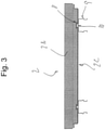
- the trays 2 have grooves 11 on the bottom surface 2C configured to interlock/interface with the guide strips 10 on the ledgers 9 (see figure 3 ), stopping the trays 2 from shifting the position and orientation over time.
- the grooves 11 have widened (chamfered) ends 12 facilitating entry of the guide strips 10 when the trays 2 are placed thereon, as can be seen in Figure 2 , in which a tray 2 is being placed on ledgers 9 by telescopic arms 7B of a shuttle 7 (not shown).
- the grooves 11 have chamfered ends 12 the entry of the guide strips 10 into the grooves 11 when performing storage of the trays 2 is facilitated while the smaller main part 13 of the grooves 11 ensures good guiding and reduction of shifting.
- the grooves 11 are configured to allow for tolerances in ledger position and thermal dilatation (thermal expansion) of the trays 2.
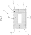
- the trays 2 are full sized (see figure 2 ) and half sized trays (see figure 4 ).
- the grooves 11 in the full sized trays 2 extend in longitudinal direction (see figure 2 ) and the grooves in the half sized trays (see figure 4 ) extend in lateral direction.
- the orientation of the grooves depend on the storage orientation of the goods carriers. This use allows to optimize storage space meaning that based on footprint two half size trays 2 are the same size as a full sized trays. Similar to paper sizes, for example A5 is half of A4 size.
- each goods carrier Preferably only a single goods is placed on or in each goods carrier. It is however also possible to place two or more goods on or in each goods carrier.
- the trays 2 have pockets 14 correspondingly located in respective opposite walls configured to allow interaction with the load handling means 7B of the shuttle 7. So it is possible to "grab" the trays 2 from the side making the pushing and pulling from behind/front unnecessary. This in turn allows a gapless storage of the goods carriers, which increases space usage in the rack (see figure 5 ).
- Such gapless storage has additional advantages in that the goods carriers abutting each other stabilize the respective positions as no space for movement exists between the goods carriers reducing shifting.
- the trays 2 have two corresponding pockets in each respective wall. So there is a pocket 14A in the front end and one pocket 14B in back end of the respective wall. This eases storage and retrieval, as the pockets 14 may be used in different ways. For example the rear pockets 14B in travel direction are used for storage of the trays, i.e. pushing them off the shuttle, allowing for deeper storage if necessary. Whereas the front pockets 14A are used for retrieval of the trays, i.e. pulling them onto the shuttle 7, allowing for shorter extension of the telescopic arms 7B, saving cycle time.
- the pockets 14 are recesses in the side wall 15 or end wall 16.
- the trays 2 have a rectangular base (bottom) with raised circumferential walls, two side walls 15 and two end walls 16 (front and back).
- the shuttle 7 includes a load carrying area 17 for carrying at least one tray 2.
- the load carrying area 17 has telescopic arms 7B (load handling means) arranged on opposite sides and at least one of them is configured with at least one finger 16 that can change between a retracted non-use position and an extended essentially horizontally orientated use position using a linear movement mechanism 18.
- the fingers 16 engage into the pockets 14 in the use position.
- the fingers 16 are linearly retracted or extended by linear movement mechanism 18. This allows to reduce the distance between the telescopic arms 7B and the trays 2 as no room for a swivelling movement as in the prior art is necessary (see figure 6 ). This in turn enables to shorten the extension movement and a simpler design of the telescope extraction.
- FIG 6 which shows a conventional twistable or rotary finger on the left hand side in comparison to a linear movement finger on the right hand side, the rotary finger would contact the upper rim of the respective wall, needing more space to engage the pockets 14, if rotary fingers were used.
- linearly moveable fingers of the present invention need hardly any distance and only need to extend a small portion to bridge the gap between pocket and telescopic arm to engage the tray 2.
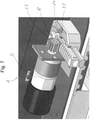
- the linear movement mechanism 18 includes a gear 19 and pinion 20 mechanism driven by an electrical gear motor 21. This drive arrangement is fixed to the telescopic arm on the opposite side of the load carrying area 17.
- the linear movement mechanism 18 also includes a mechanical end stop detector 22 for both retraction and extension movement.
- the mechanical end stops have dampening properties in order to reduce exerted peak forces to finger, pinion, drive gear and motor.
Abstract
System for storage of goods carriers with a rack having storage shelves for the goods carriers on multiple levels, with a rack-servicing machine for storage of goods carriers into the storage shelves and for discharge of goods carriers from the storage shelves, the rack-servicing machine running along tracks extending the longitudinal extension of the rack, preferably in an aisle between two racks, and configured to service at least one level, wherein the goods carriers have at least two pockets correspondingly located in respective opposite side walls configured to allow interaction with the load handling means of the rack-servicing machine.
Description
- The invention relates to a system for storage of goods carriers according to
claim 1. - The use of goods carriers (trays, containers, totes etc.) for storage and handling of goods in order fulfilment systems is known.
- They allow the standardization of material handling processes and devices even for small goods, which could otherwise not be handled safely in an automated fashion.
- Such goods carriers are handled by automated storage and retrieval systems in automated warehouses, distribution centers and order fulfilment systems.
- For example
US 2011/008138 A1 discloses a transferring shuttle, which transfers package(s) between a pair of layered stacked racks in a three dimensional automated warehouse, includes a mobile platform which runs between the stacked racks; elastic mechanisms, which include telescoping rails that extend into the stacked racks and surround a package; and terminal fingers placed at the ends of the rails, which can move between an extended position, which allows the package to be engaged and a contracted position. The rails also contain inner fingers between the terminal fingers. The inner fingers can push the package further into the stacked rack than previously possible. - These fingers swivel between an upright non-use position and an essentially extended horizontal use position, in which the fingers are positioned behind or in front of a goods carriers, tray, container etc. to pull or push it in determined direction.
- Such use of fingers to handle the goods carriers has become an industry standard.
It does however have certain disadvantages.
If the goods carriers are stored double-deep or more, the telescope with the fingers needs to extend far into the rack, which in turn means that either the telescopes have a complicated construction or the automated storage and retrieval systems are larger in width to compensate for the multi-part telescopes. - Additionally, the goods carriers need to have space between them, so that the fingers may be positioned behind a goods carrier to pull it off a shelf onto the automated storage and retrieval system.
Such gap however also leads to possible shifting of position and/or orientation of the goods carriers, which generates faults when trying to pull these of the shelves. - The object of the present invention is therefore to provide a system in which such errors are at least reduced but preferably eliminated and in which the goods carriers may be stored in a more efficient, compact manner (multiple deep) and safely handled, by simplifying the telescopic extractor.
- This object is achieved by the system described in
claim 1. Advantageous embodiments are apparent from the subordinate claims and the description. - It has been recognized that if the goods carriers have at least two pockets correspondingly located in respective opposite walls configured to allow interaction with the load handling means of the rack-servicing machine, it is possible to "grab" the goods carriers from the side rather than pushing and pulling from behind/front. This in turn allows a gapless storage of the goods carriers, which increases reach of servicing machine and space usage in the rack.
Such gapless storage has additional advantages in that the goods carriers abutting each other stabilize the respective positions as no space for movement exists between the goods carriers reducing shifting. - Beneficially the goods carriers have two corresponding pockets in each respective wall, one in each end area of the wall. This eases storage and retrieval, as the pockets may be used in different ways. For example the rear pockets in travel direction may be used for storage of the goods carriers, i.e. pushing them off the rack-servicing machine, allowing for deeper storage if necessary.
Whereas the front pockets may be used for retrieval of the goods carriers, i.e. pulling them onto the rack-servicing machine, allowing for shorter extension of the load handling means of the rack-servicing machine, saving cycle time. - Preferably the pockets are recesses or cavities in the wall. In other words, the goods carrier will have a rectangular base (bottom) with raised circumferential walls, two side walls and two end walls (front and back).
- It is also preferred that the load handling means of the rack-servicing machine includes a load carrying area for carrying at least one goods carrier, the load carrying area having telescopic arms (load handling means) arranged on opposite sides and each configured with at least two fingers that can change between a retracted non-use position and an extended, preferably essentially horizontally orientated, use position using a movement mechanism.
The fingers may be configured to engage into the pockets in the use position.
To do so, it is preferred that the fingers are linearly retracted or extended by a movement mechanism. This allows to reduce the distance between the telescopic arms (load handling means) and the goods carriers as no room for a swivelling movement as in the prior art is necessary. This in turn enables to shorten the extension movement. - An option for the linear movement mechanism includes a driven gear and pinion mechanism.
- The linear movement mechanism may also include an end stop detector. The end stop detector may be mechanical and/or electrical. Preferably the linear movement mechanism includes a mechanical end stop for both retraction and extension movement. A proximity switch may be arranged and used to detect the position of the finger. In case of mechanical limits these shall have dampening properties in order to reduce force peaks and therefore increase life expectancy of the engaged elements.
- The rack of the gear and pinion mechanism is preferably simultaneously used as a finger. Extension and reaction movement is primarily stopped by a mechanical end stop. Additionally one or more electromagnetic sensor(s) signal the current position of the finger. This functionality ensures the safety of the operating system and collisions between good carriers and fingers are reduced.
- To further optimize space utilization, the goods carriers are preferably full sized and half sized goods carriers.
This meaning that based on footprint two half size goods carriers are the same size as a full sized goods carrier. Similar to paper sizes, for example A5 is half of A4 size. Small goods are placed / stored on the half size goods carriers and larger goods on the full sized goods carriers.
This allows to either place a full sized goods carrier or two half sized goods carriers (rotated) in the same space.
Preferably only a single goods is placed on or in each goods carrier. It is however also possible to place two or more goods on or in each goods carrier. - The pockets in the full sized goods carriers will be in the side walls (longer walls). The pockets in the half sized goods carriers will be in the end walls (front and back).
- The rack-servicing machines may be single level servicing automated storage and retrieval machines of the shuttle type. These will preferably be configured to carry a single full sized goods carrier or two half size goods carriers (in rotated orientation, i.e. long side next to long side).
- Preferably the goods carriers are trays, even more preferred trays of the two-piece kind. The trays used have a two-piece design that allows for safe transport and easy defraying. They comprise a frame and within that frame a moveable bottom as detailed in
DE 10 2008 026 326 A1 - Further features and details of the invention will be apparent from the description hereinafter of the drawing, in which
-
Fig. 1 shows a schematic side view of a system according to the invention; -
Fig. 2 shows a schematic top view of a system offigure 1 with a full sized goods carrier being placed; -
Fig. 3 shows a side view of full sized goods carrier being placed on ledgers; -
Fig. 4 shows a bottom view of a half size goods carrier with indication of guide strips; -
Fig. 5 shows a schematic top view of a system offigure 1 with half sized goods carriers on the shelf in a gapless arrangement and -
Fig. 6 shows a comparison of traditional rotary fingers vs the inventive linear fingers as well as -
Fig. 7 shows a schematic perspective view of a linear movement mechanism of the fingers. - In the figures a system designated as a whole with 1 for storage of goods carriers is shown. In the present case the goods carriers are
trays 2. - The
trays 2 used have a two-piece design that allows for safe transport and easy defraying. They comprise a frame 2A and within that frame a moveable bottom 2B as detailed inDE 10 2008 026 326 A1 - The system includes a rack 3 having
storage shelves 4 for thetrays 2 on multiple levels. - The rack 3 has a vertical lift 5 for vertical movement of
trays 2 between levels. Thetrays 2 are dropped off or picked up by the rack-servicing machines besides the lift 5 on buffers (not shown) that interface with the lift 5 (or its carriage).
In one level the lift 5 interfaces with aconveyor 6 for supply and discharge oftrays 2 to the rack 3. - The rack-
servicing machines 7 for storage oftrays 2 into thestorage shelves 4 and for discharge oftrays 2 from thestorage shelves 4 are of the shuttle type and run alongtracks 8 extending the longitudinal extension of the rack 3 in an aisle between two racks 3 and are configured to service at least one level.
Theshuttles 7 are configured to carry a single fullsized tray 2 or two half sized trays 2 (in rotated orientation, i.e. long side next to long side). This depends on the size of the full sized tray. If two full size trays would fit onto the shuttle, then these shall be carried as such as well in order to increase performance. - The
storage shelves 4 are formed withledgers 9 having guide strips 10. - The
ledgers 9 are arranged perpendicular to the longitudinal extension of the rack 3 (or aisle). Twoledgers 9 support eachtray 2 from below. Theledgers 9 are arranged along the storage space of each level/shelf 4 in a pattern. - The guide strips 10 on the
ledgers 9 are formed by upwards facing raised beadings extending the length of theledgers 9 preferably but not necessarily along the middle line. - The
trays 2 have grooves 11 on the bottom surface 2C configured to interlock/interface with the guide strips 10 on the ledgers 9 (seefigure 3 ), stopping thetrays 2 from shifting the position and orientation over time. - The grooves 11 have widened (chamfered) ends 12 facilitating entry of the guide strips 10 when the
trays 2 are placed thereon, as can be seen inFigure 2 , in which atray 2 is being placed onledgers 9 bytelescopic arms 7B of a shuttle 7 (not shown). - As the grooves 11 have chamfered ends 12 the entry of the guide strips 10 into the grooves 11 when performing storage of the
trays 2 is facilitated while the smallermain part 13 of the grooves 11 ensures good guiding and reduction of shifting. - The grooves 11 are configured to allow for tolerances in ledger position and thermal dilatation (thermal expansion) of the
trays 2. - The
trays 2 are full sized (seefigure 2 ) and half sized trays (seefigure 4 ). The grooves 11 in the fullsized trays 2 extend in longitudinal direction (seefigure 2 ) and the grooves in the half sized trays (seefigure 4 ) extend in lateral direction. The orientation of the grooves depend on the storage orientation of the goods carriers. This use allows to optimize storage space meaning that based on footprint twohalf size trays 2 are the same size as a full sized trays. Similar to paper sizes, for example A5 is half of A4 size. - Preferably only a single goods is placed on or in each goods carrier. It is however also possible to place two or more goods on or in each goods carrier.
- The
trays 2 havepockets 14 correspondingly located in respective opposite walls configured to allow interaction with the load handling means 7B of theshuttle 7. So it is possible to "grab" thetrays 2 from the side making the pushing and pulling from behind/front unnecessary. This in turn allows a gapless storage of the goods carriers, which increases space usage in the rack (seefigure 5 ).
Such gapless storage has additional advantages in that the goods carriers abutting each other stabilize the respective positions as no space for movement exists between the goods carriers reducing shifting. - The
trays 2 have two corresponding pockets in each respective wall. So there is apocket 14A in the front end and onepocket 14B in back end of the respective wall. This eases storage and retrieval, as thepockets 14 may be used in different ways. For example therear pockets 14B in travel direction are used for storage of the trays, i.e. pushing them off the shuttle, allowing for deeper storage if necessary.
Whereas the front pockets 14A are used for retrieval of the trays, i.e. pulling them onto theshuttle 7, allowing for shorter extension of thetelescopic arms 7B, saving cycle time. - As can be deduced from
figure 5 , depending on size oftray 2, two trays can be handled at the same time. In the present case two half sized trays can be handled and also carried at the same time. - The
pockets 14 are recesses in theside wall 15 orend wall 16. Thetrays 2 have a rectangular base (bottom) with raised circumferential walls, twoside walls 15 and two end walls 16 (front and back). - The
shuttle 7 includes a load carrying area 17 for carrying at least onetray 2. The load carrying area 17 hastelescopic arms 7B (load handling means) arranged on opposite sides and at least one of them is configured with at least onefinger 16 that can change between a retracted non-use position and an extended essentially horizontally orientated use position using a linear movement mechanism 18.
Thefingers 16 engage into thepockets 14 in the use position. - To do so, the
fingers 16 are linearly retracted or extended by linear movement mechanism 18. This allows to reduce the distance between thetelescopic arms 7B and thetrays 2 as no room for a swivelling movement as in the prior art is necessary (seefigure 6 ). This in turn enables to shorten the extension movement and a simpler design of the telescope extraction. - As can be seen in
figure 6 , which shows a conventional twistable or rotary finger on the left hand side in comparison to a linear movement finger on the right hand side, the rotary finger would contact the upper rim of the respective wall, needing more space to engage thepockets 14, if rotary fingers were used. - In contrast the linearly moveable fingers of the present invention need hardly any distance and only need to extend a small portion to bridge the gap between pocket and telescopic arm to engage the
tray 2. - The linear movement mechanism 18 includes a
gear 19 and pinion 20 mechanism driven by anelectrical gear motor 21. This drive arrangement is fixed to the telescopic arm on the opposite side of the load carrying area 17. - The linear movement mechanism 18 also includes a mechanical
end stop detector 22 for both retraction and extension movement. The mechanical end stops have dampening properties in order to reduce exerted peak forces to finger, pinion, drive gear and motor. There is at least one proximity switch in order to safely recognize at least one defined position of the finger.
Claims (11)
- System for storage of goods carriers with a rack having storage shelves for the goods carriers on multiple levels, with a rack-servicing machine for storage of goods carriers into the storage shelves and for discharge of goods carriers from the storage shelves, the rack-servicing machine running along tracks extending the longitudinal extension of the rack, preferably in an aisle between two racks, and configured to service at least one level, characterized in that
the goods carriers have at least two pockets correspondingly located in respective opposite walls configured to allow interaction with the load handling means of the rack-servicing machine. - System according to claim 1, characterized in that goods carriers have two corresponding pockets in each respective wall, one in each end area of the wall.
- System according to claim 1 or 2, characterized in that pockets are recesses or cavities in the wall.
- System according to any preceding claim, characterized in that the load handling means of the rack-servicing machine includes a load carrying area for carrying at least one goods carrier, the load carrying area having telescopic arms arranged on opposite sides and each configured with at least two fingers that can change between a retracted non-use position and an extended, preferably essentially horizontally orientated, use position using a movement mechanism.
- System according to claim 4, characterized in that the fingers engage into the pockets in the use position.
- System according to any preceding claim, characterized in that the fingers are linearly retracted or extended by a movement mechanism.
- System according to claim 6, characterized in that the linear movement mechanism includes a driven gear and pinion mechanism.
- System according to any preceding claim 6 or 7, characterized in that linear movement mechanism includes a mechanical end stop for both retraction and extension movement.
- System according to claim 8, characterized in that the mechanical end stop has dampening properties and includes at least one proximity switch in order to safely recognize at least one defined position of the finger.
- System according to any preceding claim, characterized in that the goods carriers are full sized and half sized goods carriers.
- System according to any preceding claim, characterized in that the goods carriers are trays.
Priority Applications (8)
| Application Number | Priority Date | Filing Date | Title |
|---|---|---|---|
| EP20192434.7A EP3960656A1 (en) | 2020-08-24 | 2020-08-24 | System for storage of goods carriers |
| CN202180050820.XA CN115884928A (en) | 2020-08-24 | 2021-08-16 | System for storing cargo carriers |
| AU2021334848A AU2021334848A1 (en) | 2020-08-24 | 2021-08-16 | System for storage of goods carriers |
| PCT/EP2021/072751 WO2022043116A1 (en) | 2020-08-24 | 2021-08-16 | System for storage of goods carriers |
| CA3189421A CA3189421A1 (en) | 2020-08-24 | 2021-08-16 | System for storage of goods carriers |
| KR1020237010128A KR20230056745A (en) | 2020-08-24 | 2021-08-16 | Systems for the storage of goods carriers |
| EP21759099.1A EP4200234A1 (en) | 2020-08-24 | 2021-08-16 | System for storage of goods carriers |
| US18/042,414 US20230322489A1 (en) | 2020-08-24 | 2021-08-16 | System for storage of goods carriers |
Applications Claiming Priority (1)
| Application Number | Priority Date | Filing Date | Title |
|---|---|---|---|
| EP20192434.7A EP3960656A1 (en) | 2020-08-24 | 2020-08-24 | System for storage of goods carriers |
Publications (1)
| Publication Number | Publication Date |
|---|---|
| EP3960656A1 true EP3960656A1 (en) | 2022-03-02 |
Family
ID=72234735
Family Applications (2)
| Application Number | Title | Priority Date | Filing Date |
|---|---|---|---|
| EP20192434.7A Withdrawn EP3960656A1 (en) | 2020-08-24 | 2020-08-24 | System for storage of goods carriers |
| EP21759099.1A Pending EP4200234A1 (en) | 2020-08-24 | 2021-08-16 | System for storage of goods carriers |
Family Applications After (1)
| Application Number | Title | Priority Date | Filing Date |
|---|---|---|---|
| EP21759099.1A Pending EP4200234A1 (en) | 2020-08-24 | 2021-08-16 | System for storage of goods carriers |
Country Status (7)
| Country | Link |
|---|---|
| US (1) | US20230322489A1 (en) |
| EP (2) | EP3960656A1 (en) |
| KR (1) | KR20230056745A (en) |
| CN (1) | CN115884928A (en) |
| AU (1) | AU2021334848A1 (en) |
| CA (1) | CA3189421A1 (en) |
| WO (1) | WO2022043116A1 (en) |
Citations (4)
| Publication number | Priority date | Publication date | Assignee | Title |
|---|---|---|---|---|
| US4743157A (en) * | 1985-12-13 | 1988-05-10 | Yoshida Kogyo K. K. | Vehicle with goods loading/unloading apparatus |
| DE102008026326A1 (en) | 2008-05-31 | 2009-12-03 | Dematic Gmbh | Flat load carrier i.e. tray, for retaining conveying goods to be stored in rack and to be transported to conveying system, has base plate movable within frame over height of circular edge of frame between two stops |
| US20110008138A1 (en) | 2008-10-27 | 2011-01-13 | Dematic Gmbh | Transferring shuttle for three dimensional automated warehouse |
| US7991505B2 (en) * | 2003-08-29 | 2011-08-02 | Casepick Systems, Llc | Materials-handling system using autonomous transfer and transport vehicles |
Family Cites Families (3)
| Publication number | Priority date | Publication date | Assignee | Title |
|---|---|---|---|---|
| US4856956A (en) * | 1987-06-18 | 1989-08-15 | Supac Systems, Inc. | Container extraction and transfer mechanism for an automated storage and retrieval system |
| JP4678715B2 (en) * | 2004-12-09 | 2011-04-27 | 西部電機株式会社 | Loading system |
| AT506284A1 (en) * | 2007-12-21 | 2009-07-15 | Tgw Mechanics Gmbh | METHOD FOR STORING LOADING TOOLS AND TRANSPORT DEVICE |
-
2020
- 2020-08-24 EP EP20192434.7A patent/EP3960656A1/en not_active Withdrawn
-
2021
- 2021-08-16 CA CA3189421A patent/CA3189421A1/en active Pending
- 2021-08-16 KR KR1020237010128A patent/KR20230056745A/en unknown
- 2021-08-16 CN CN202180050820.XA patent/CN115884928A/en active Pending
- 2021-08-16 US US18/042,414 patent/US20230322489A1/en active Pending
- 2021-08-16 AU AU2021334848A patent/AU2021334848A1/en active Pending
- 2021-08-16 EP EP21759099.1A patent/EP4200234A1/en active Pending
- 2021-08-16 WO PCT/EP2021/072751 patent/WO2022043116A1/en unknown
Patent Citations (4)
| Publication number | Priority date | Publication date | Assignee | Title |
|---|---|---|---|---|
| US4743157A (en) * | 1985-12-13 | 1988-05-10 | Yoshida Kogyo K. K. | Vehicle with goods loading/unloading apparatus |
| US7991505B2 (en) * | 2003-08-29 | 2011-08-02 | Casepick Systems, Llc | Materials-handling system using autonomous transfer and transport vehicles |
| DE102008026326A1 (en) | 2008-05-31 | 2009-12-03 | Dematic Gmbh | Flat load carrier i.e. tray, for retaining conveying goods to be stored in rack and to be transported to conveying system, has base plate movable within frame over height of circular edge of frame between two stops |
| US20110008138A1 (en) | 2008-10-27 | 2011-01-13 | Dematic Gmbh | Transferring shuttle for three dimensional automated warehouse |
Also Published As
| Publication number | Publication date |
|---|---|
| WO2022043116A1 (en) | 2022-03-03 |
| AU2021334848A1 (en) | 2023-03-09 |
| CA3189421A1 (en) | 2022-03-03 |
| CN115884928A (en) | 2023-03-31 |
| EP4200234A1 (en) | 2023-06-28 |
| KR20230056745A (en) | 2023-04-27 |
| US20230322489A1 (en) | 2023-10-12 |
Similar Documents
| Publication | Publication Date | Title |
|---|---|---|
| EP3653538B1 (en) | Transport vehicle and transport facility | |
| US10589928B2 (en) | Storage and retrieval machine | |
| US20110194917A1 (en) | Storage Rack | |
| US8075238B2 (en) | Device and method for running a warehouse | |
| EP1726539A1 (en) | Apparatus and method for stocking bulky loads | |
| US3608749A (en) | Plural depth storage system with a plurality of article handling means | |
| US3933257A (en) | Warehouse shelving system | |
| CN212558114U (en) | Unmanned distribution system | |
| CN105151613A (en) | Lifting-stacking type automatic stereoscopic storehouse | |
| CN116081155A (en) | Pallet material rack mechanism | |
| EP3960656A1 (en) | System for storage of goods carriers | |
| US11117790B2 (en) | Industrial truck comprising a thrust device | |
| CN111137812A (en) | Carrying trolley | |
| JP6870370B2 (en) | Stacker crane and automated warehouse | |
| JP4678715B2 (en) | Loading system | |
| CN110525866B (en) | Automatic goods shelf conveying system and conveying method thereof | |
| KR20230074264A (en) | Container storage and retrieval system | |
| EP1505009B1 (en) | Apparatus for storing materials | |
| EP2452899B1 (en) | Apparatus for the automated handling of loading units in warehouses equipped with shelf-like structures | |
| EP3960655A1 (en) | System for storage of goods carriers | |
| JPH0364405B2 (en) | ||
| CN215945696U (en) | Goods shelves system and intelligent warehouse that has it | |
| JP2000327112A (en) | Automatic storage and retrieval facilities | |
| CN215325677U (en) | Intelligent tray warehouse | |
| CN117105131A (en) | telescopic fork |
Legal Events
| Date | Code | Title | Description |
|---|---|---|---|
| PUAI | Public reference made under article 153(3) epc to a published international application that has entered the european phase |
Free format text: ORIGINAL CODE: 0009012 |
|
| STAA | Information on the status of an ep patent application or granted ep patent |
Free format text: STATUS: THE APPLICATION HAS BEEN PUBLISHED |
|
| AK | Designated contracting states |
Kind code of ref document: A1 Designated state(s): AL AT BE BG CH CY CZ DE DK EE ES FI FR GB GR HR HU IE IS IT LI LT LU LV MC MK MT NL NO PL PT RO RS SE SI SK SM TR |
|
| STAA | Information on the status of an ep patent application or granted ep patent |
Free format text: STATUS: THE APPLICATION IS DEEMED TO BE WITHDRAWN |
|
| 18D | Application deemed to be withdrawn |
Effective date: 20220903 |