WO2010044132A1 - ハイブリッド車両の制御装置および制御方法 - Google Patents
ハイブリッド車両の制御装置および制御方法 Download PDFInfo
- Publication number
- WO2010044132A1 WO2010044132A1 PCT/JP2008/068539 JP2008068539W WO2010044132A1 WO 2010044132 A1 WO2010044132 A1 WO 2010044132A1 JP 2008068539 W JP2008068539 W JP 2008068539W WO 2010044132 A1 WO2010044132 A1 WO 2010044132A1
- Authority
- WO
- WIPO (PCT)
- Prior art keywords
- control
- rotating electrical
- electrical machine
- travel
- hybrid
- Prior art date
Links
Images


Classifications
-
- B—PERFORMING OPERATIONS; TRANSPORTING
- B60—VEHICLES IN GENERAL
- B60K—ARRANGEMENT OR MOUNTING OF PROPULSION UNITS OR OF TRANSMISSIONS IN VEHICLES; ARRANGEMENT OR MOUNTING OF PLURAL DIVERSE PRIME-MOVERS IN VEHICLES; AUXILIARY DRIVES FOR VEHICLES; INSTRUMENTATION OR DASHBOARDS FOR VEHICLES; ARRANGEMENTS IN CONNECTION WITH COOLING, AIR INTAKE, GAS EXHAUST OR FUEL SUPPLY OF PROPULSION UNITS IN VEHICLES
- B60K6/00—Arrangement or mounting of plural diverse prime-movers for mutual or common propulsion, e.g. hybrid propulsion systems comprising electric motors and internal combustion engines ; Control systems therefor, i.e. systems controlling two or more prime movers, or controlling one of these prime movers and any of the transmission, drive or drive units Informative references: mechanical gearings with secondary electric drive F16H3/72; arrangements for handling mechanical energy structurally associated with the dynamo-electric machine H02K7/00; machines comprising structurally interrelated motor and generator parts H02K51/00; dynamo-electric machines not otherwise provided for in H02K see H02K99/00
- B60K6/20—Arrangement or mounting of plural diverse prime-movers for mutual or common propulsion, e.g. hybrid propulsion systems comprising electric motors and internal combustion engines ; Control systems therefor, i.e. systems controlling two or more prime movers, or controlling one of these prime movers and any of the transmission, drive or drive units Informative references: mechanical gearings with secondary electric drive F16H3/72; arrangements for handling mechanical energy structurally associated with the dynamo-electric machine H02K7/00; machines comprising structurally interrelated motor and generator parts H02K51/00; dynamo-electric machines not otherwise provided for in H02K see H02K99/00 the prime-movers consisting of electric motors and internal combustion engines, e.g. HEVs
- B60K6/42—Arrangement or mounting of plural diverse prime-movers for mutual or common propulsion, e.g. hybrid propulsion systems comprising electric motors and internal combustion engines ; Control systems therefor, i.e. systems controlling two or more prime movers, or controlling one of these prime movers and any of the transmission, drive or drive units Informative references: mechanical gearings with secondary electric drive F16H3/72; arrangements for handling mechanical energy structurally associated with the dynamo-electric machine H02K7/00; machines comprising structurally interrelated motor and generator parts H02K51/00; dynamo-electric machines not otherwise provided for in H02K see H02K99/00 the prime-movers consisting of electric motors and internal combustion engines, e.g. HEVs characterised by the architecture of the hybrid electric vehicle
- B60K6/44—Series-parallel type
- B60K6/445—Differential gearing distribution type
-
- B—PERFORMING OPERATIONS; TRANSPORTING
- B60—VEHICLES IN GENERAL
- B60W—CONJOINT CONTROL OF VEHICLE SUB-UNITS OF DIFFERENT TYPE OR DIFFERENT FUNCTION; CONTROL SYSTEMS SPECIALLY ADAPTED FOR HYBRID VEHICLES; ROAD VEHICLE DRIVE CONTROL SYSTEMS FOR PURPOSES NOT RELATED TO THE CONTROL OF A PARTICULAR SUB-UNIT
- B60W20/00—Control systems specially adapted for hybrid vehicles
- B60W20/40—Controlling the engagement or disengagement of prime movers, e.g. for transition between prime movers
-
- B—PERFORMING OPERATIONS; TRANSPORTING
- B60—VEHICLES IN GENERAL
- B60K—ARRANGEMENT OR MOUNTING OF PROPULSION UNITS OR OF TRANSMISSIONS IN VEHICLES; ARRANGEMENT OR MOUNTING OF PLURAL DIVERSE PRIME-MOVERS IN VEHICLES; AUXILIARY DRIVES FOR VEHICLES; INSTRUMENTATION OR DASHBOARDS FOR VEHICLES; ARRANGEMENTS IN CONNECTION WITH COOLING, AIR INTAKE, GAS EXHAUST OR FUEL SUPPLY OF PROPULSION UNITS IN VEHICLES
- B60K6/00—Arrangement or mounting of plural diverse prime-movers for mutual or common propulsion, e.g. hybrid propulsion systems comprising electric motors and internal combustion engines ; Control systems therefor, i.e. systems controlling two or more prime movers, or controlling one of these prime movers and any of the transmission, drive or drive units Informative references: mechanical gearings with secondary electric drive F16H3/72; arrangements for handling mechanical energy structurally associated with the dynamo-electric machine H02K7/00; machines comprising structurally interrelated motor and generator parts H02K51/00; dynamo-electric machines not otherwise provided for in H02K see H02K99/00
- B60K6/20—Arrangement or mounting of plural diverse prime-movers for mutual or common propulsion, e.g. hybrid propulsion systems comprising electric motors and internal combustion engines ; Control systems therefor, i.e. systems controlling two or more prime movers, or controlling one of these prime movers and any of the transmission, drive or drive units Informative references: mechanical gearings with secondary electric drive F16H3/72; arrangements for handling mechanical energy structurally associated with the dynamo-electric machine H02K7/00; machines comprising structurally interrelated motor and generator parts H02K51/00; dynamo-electric machines not otherwise provided for in H02K see H02K99/00 the prime-movers consisting of electric motors and internal combustion engines, e.g. HEVs
- B60K6/22—Arrangement or mounting of plural diverse prime-movers for mutual or common propulsion, e.g. hybrid propulsion systems comprising electric motors and internal combustion engines ; Control systems therefor, i.e. systems controlling two or more prime movers, or controlling one of these prime movers and any of the transmission, drive or drive units Informative references: mechanical gearings with secondary electric drive F16H3/72; arrangements for handling mechanical energy structurally associated with the dynamo-electric machine H02K7/00; machines comprising structurally interrelated motor and generator parts H02K51/00; dynamo-electric machines not otherwise provided for in H02K see H02K99/00 the prime-movers consisting of electric motors and internal combustion engines, e.g. HEVs characterised by apparatus, components or means specially adapted for HEVs
- B60K6/28—Arrangement or mounting of plural diverse prime-movers for mutual or common propulsion, e.g. hybrid propulsion systems comprising electric motors and internal combustion engines ; Control systems therefor, i.e. systems controlling two or more prime movers, or controlling one of these prime movers and any of the transmission, drive or drive units Informative references: mechanical gearings with secondary electric drive F16H3/72; arrangements for handling mechanical energy structurally associated with the dynamo-electric machine H02K7/00; machines comprising structurally interrelated motor and generator parts H02K51/00; dynamo-electric machines not otherwise provided for in H02K see H02K99/00 the prime-movers consisting of electric motors and internal combustion engines, e.g. HEVs characterised by apparatus, components or means specially adapted for HEVs characterised by the electric energy storing means, e.g. batteries or capacitors
-
- B—PERFORMING OPERATIONS; TRANSPORTING
- B60—VEHICLES IN GENERAL
- B60L—PROPULSION OF ELECTRICALLY-PROPELLED VEHICLES; SUPPLYING ELECTRIC POWER FOR AUXILIARY EQUIPMENT OF ELECTRICALLY-PROPELLED VEHICLES; ELECTRODYNAMIC BRAKE SYSTEMS FOR VEHICLES IN GENERAL; MAGNETIC SUSPENSION OR LEVITATION FOR VEHICLES; MONITORING OPERATING VARIABLES OF ELECTRICALLY-PROPELLED VEHICLES; ELECTRIC SAFETY DEVICES FOR ELECTRICALLY-PROPELLED VEHICLES
- B60L50/00—Electric propulsion with power supplied within the vehicle
- B60L50/10—Electric propulsion with power supplied within the vehicle using propulsion power supplied by engine-driven generators, e.g. generators driven by combustion engines
-
- B—PERFORMING OPERATIONS; TRANSPORTING
- B60—VEHICLES IN GENERAL
- B60L—PROPULSION OF ELECTRICALLY-PROPELLED VEHICLES; SUPPLYING ELECTRIC POWER FOR AUXILIARY EQUIPMENT OF ELECTRICALLY-PROPELLED VEHICLES; ELECTRODYNAMIC BRAKE SYSTEMS FOR VEHICLES IN GENERAL; MAGNETIC SUSPENSION OR LEVITATION FOR VEHICLES; MONITORING OPERATING VARIABLES OF ELECTRICALLY-PROPELLED VEHICLES; ELECTRIC SAFETY DEVICES FOR ELECTRICALLY-PROPELLED VEHICLES
- B60L50/00—Electric propulsion with power supplied within the vehicle
- B60L50/50—Electric propulsion with power supplied within the vehicle using propulsion power supplied by batteries or fuel cells
- B60L50/60—Electric propulsion with power supplied within the vehicle using propulsion power supplied by batteries or fuel cells using power supplied by batteries
- B60L50/66—Arrangements of batteries
-
- B—PERFORMING OPERATIONS; TRANSPORTING
- B60—VEHICLES IN GENERAL
- B60L—PROPULSION OF ELECTRICALLY-PROPELLED VEHICLES; SUPPLYING ELECTRIC POWER FOR AUXILIARY EQUIPMENT OF ELECTRICALLY-PROPELLED VEHICLES; ELECTRODYNAMIC BRAKE SYSTEMS FOR VEHICLES IN GENERAL; MAGNETIC SUSPENSION OR LEVITATION FOR VEHICLES; MONITORING OPERATING VARIABLES OF ELECTRICALLY-PROPELLED VEHICLES; ELECTRIC SAFETY DEVICES FOR ELECTRICALLY-PROPELLED VEHICLES
- B60L58/00—Methods or circuit arrangements for monitoring or controlling batteries or fuel cells, specially adapted for electric vehicles
- B60L58/10—Methods or circuit arrangements for monitoring or controlling batteries or fuel cells, specially adapted for electric vehicles for monitoring or controlling batteries
- B60L58/18—Methods or circuit arrangements for monitoring or controlling batteries or fuel cells, specially adapted for electric vehicles for monitoring or controlling batteries of two or more battery modules
- B60L58/21—Methods or circuit arrangements for monitoring or controlling batteries or fuel cells, specially adapted for electric vehicles for monitoring or controlling batteries of two or more battery modules having the same nominal voltage
-
- B—PERFORMING OPERATIONS; TRANSPORTING
- B60—VEHICLES IN GENERAL
- B60W—CONJOINT CONTROL OF VEHICLE SUB-UNITS OF DIFFERENT TYPE OR DIFFERENT FUNCTION; CONTROL SYSTEMS SPECIALLY ADAPTED FOR HYBRID VEHICLES; ROAD VEHICLE DRIVE CONTROL SYSTEMS FOR PURPOSES NOT RELATED TO THE CONTROL OF A PARTICULAR SUB-UNIT
- B60W10/00—Conjoint control of vehicle sub-units of different type or different function
- B60W10/04—Conjoint control of vehicle sub-units of different type or different function including control of propulsion units
- B60W10/08—Conjoint control of vehicle sub-units of different type or different function including control of propulsion units including control of electric propulsion units, e.g. motors or generators
-
- B—PERFORMING OPERATIONS; TRANSPORTING
- B60—VEHICLES IN GENERAL
- B60W—CONJOINT CONTROL OF VEHICLE SUB-UNITS OF DIFFERENT TYPE OR DIFFERENT FUNCTION; CONTROL SYSTEMS SPECIALLY ADAPTED FOR HYBRID VEHICLES; ROAD VEHICLE DRIVE CONTROL SYSTEMS FOR PURPOSES NOT RELATED TO THE CONTROL OF A PARTICULAR SUB-UNIT
- B60W10/00—Conjoint control of vehicle sub-units of different type or different function
- B60W10/24—Conjoint control of vehicle sub-units of different type or different function including control of energy storage means
- B60W10/26—Conjoint control of vehicle sub-units of different type or different function including control of energy storage means for electrical energy, e.g. batteries or capacitors
-
- B—PERFORMING OPERATIONS; TRANSPORTING
- B60—VEHICLES IN GENERAL
- B60K—ARRANGEMENT OR MOUNTING OF PROPULSION UNITS OR OF TRANSMISSIONS IN VEHICLES; ARRANGEMENT OR MOUNTING OF PLURAL DIVERSE PRIME-MOVERS IN VEHICLES; AUXILIARY DRIVES FOR VEHICLES; INSTRUMENTATION OR DASHBOARDS FOR VEHICLES; ARRANGEMENTS IN CONNECTION WITH COOLING, AIR INTAKE, GAS EXHAUST OR FUEL SUPPLY OF PROPULSION UNITS IN VEHICLES
- B60K1/00—Arrangement or mounting of electrical propulsion units
- B60K1/02—Arrangement or mounting of electrical propulsion units comprising more than one electric motor
-
- B—PERFORMING OPERATIONS; TRANSPORTING
- B60—VEHICLES IN GENERAL
- B60W—CONJOINT CONTROL OF VEHICLE SUB-UNITS OF DIFFERENT TYPE OR DIFFERENT FUNCTION; CONTROL SYSTEMS SPECIALLY ADAPTED FOR HYBRID VEHICLES; ROAD VEHICLE DRIVE CONTROL SYSTEMS FOR PURPOSES NOT RELATED TO THE CONTROL OF A PARTICULAR SUB-UNIT
- B60W20/00—Control systems specially adapted for hybrid vehicles
-
- B—PERFORMING OPERATIONS; TRANSPORTING
- B60—VEHICLES IN GENERAL
- B60W—CONJOINT CONTROL OF VEHICLE SUB-UNITS OF DIFFERENT TYPE OR DIFFERENT FUNCTION; CONTROL SYSTEMS SPECIALLY ADAPTED FOR HYBRID VEHICLES; ROAD VEHICLE DRIVE CONTROL SYSTEMS FOR PURPOSES NOT RELATED TO THE CONTROL OF A PARTICULAR SUB-UNIT
- B60W2510/00—Input parameters relating to a particular sub-units
- B60W2510/24—Energy storage means
- B60W2510/242—Energy storage means for electrical energy
- B60W2510/244—Charge state
-
- Y—GENERAL TAGGING OF NEW TECHNOLOGICAL DEVELOPMENTS; GENERAL TAGGING OF CROSS-SECTIONAL TECHNOLOGIES SPANNING OVER SEVERAL SECTIONS OF THE IPC; TECHNICAL SUBJECTS COVERED BY FORMER USPC CROSS-REFERENCE ART COLLECTIONS [XRACs] AND DIGESTS
- Y02—TECHNOLOGIES OR APPLICATIONS FOR MITIGATION OR ADAPTATION AGAINST CLIMATE CHANGE
- Y02T—CLIMATE CHANGE MITIGATION TECHNOLOGIES RELATED TO TRANSPORTATION
- Y02T10/00—Road transport of goods or passengers
- Y02T10/60—Other road transportation technologies with climate change mitigation effect
- Y02T10/62—Hybrid vehicles
-
- Y—GENERAL TAGGING OF NEW TECHNOLOGICAL DEVELOPMENTS; GENERAL TAGGING OF CROSS-SECTIONAL TECHNOLOGIES SPANNING OVER SEVERAL SECTIONS OF THE IPC; TECHNICAL SUBJECTS COVERED BY FORMER USPC CROSS-REFERENCE ART COLLECTIONS [XRACs] AND DIGESTS
- Y02—TECHNOLOGIES OR APPLICATIONS FOR MITIGATION OR ADAPTATION AGAINST CLIMATE CHANGE
- Y02T—CLIMATE CHANGE MITIGATION TECHNOLOGIES RELATED TO TRANSPORTATION
- Y02T10/00—Road transport of goods or passengers
- Y02T10/60—Other road transportation technologies with climate change mitigation effect
- Y02T10/70—Energy storage systems for electromobility, e.g. batteries
-
- Y—GENERAL TAGGING OF NEW TECHNOLOGICAL DEVELOPMENTS; GENERAL TAGGING OF CROSS-SECTIONAL TECHNOLOGIES SPANNING OVER SEVERAL SECTIONS OF THE IPC; TECHNICAL SUBJECTS COVERED BY FORMER USPC CROSS-REFERENCE ART COLLECTIONS [XRACs] AND DIGESTS
- Y02—TECHNOLOGIES OR APPLICATIONS FOR MITIGATION OR ADAPTATION AGAINST CLIMATE CHANGE
- Y02T—CLIMATE CHANGE MITIGATION TECHNOLOGIES RELATED TO TRANSPORTATION
- Y02T10/00—Road transport of goods or passengers
- Y02T10/60—Other road transportation technologies with climate change mitigation effect
- Y02T10/7072—Electromobility specific charging systems or methods for batteries, ultracapacitors, supercapacitors or double-layer capacitors
Definitions
- the present invention relates to control of a hybrid vehicle, and more particularly, to control of a hybrid vehicle including a plurality of power sources capable of receiving and transmitting power with a rotating electrical machine as a power source.
- Hybrid vehicles are equipped with a power source that can exchange electric power with a rotating electrical machine that is a power source.
- Patent Document 1 discloses a hybrid vehicle including a power supply control system for using a high voltage inverter and a motor in a low voltage battery module.
- a power supply control system disclosed in Japanese Patent Application Laid-Open No. 2003-209969 includes at least one inverter that provides adjusted electric power to an electric traction motor of a vehicle, and each includes a battery, a boost / buck DC / DC A plurality of power supply stages having a converter, wired in parallel, and providing DC power to at least one inverter; The power supply stage is controlled to maintain an output voltage to at least one inverter.
- Patent Document 1 includes at least one inverter that provides adjusted electric power to an electric traction motor of a vehicle, and each includes a battery, a boost / buck DC / DC A plurality of power supply stages having a converter, wired in parallel, and providing DC power to at least one inverter; The power supply stage is controlled to maintain an output voltage to at least one inverter.
- a hybrid vehicle usually has an electric travel mode and a hybrid travel mode as travel modes. These travel modes differ in the voltage range to be supplied to the motor.
- the vehicle in the hybrid travel mode, the vehicle is driven using the power of both the engine and the motor, so that the voltage supplied to the motor can be set lower than in the electric travel mode using only the power of the motor. Become.
- Patent Document 1 discloses a hybrid vehicle having a plurality of power sources capable of receiving and transmitting electric power to and from a motor. No mention is made of how to control the state and what value the output voltage of each power supply is set in consideration of the driving mode and the connection state of a plurality of power supplies.
- the present invention has been made to solve the above-described problem, and an object of the present invention is to secure a necessary power capacity in the electric travel mode in a hybrid vehicle having the electric travel mode and the hybrid travel mode as travel modes.
- an object of the present invention is to secure a necessary power capacity in the electric travel mode in a hybrid vehicle having the electric travel mode and the hybrid travel mode as travel modes.
- it is to provide a control device and a control method capable of setting the power supply voltage at the time of hybrid travel control to an optimum value.
- the control device controls a hybrid vehicle that uses at least one of an internal combustion engine and a rotating electric machine as a power source.
- the control device is connected to the rotating electrical machine and is provided between the main power source capable of transmitting and receiving electric power to and from the rotating electrical machine, a plurality of sub power sources capable of transmitting and receiving power to and from the rotating electrical machine, and the plurality of sub power sources and the rotating electrical machine.
- a switching device configured to be able to connect any one of a plurality of sub-power supplies to the rotating electrical machine according to a given command, a switching control unit that controls the switching device, and at least one of the power of the internal combustion engine and the rotating electrical machine.
- a travel control unit that executes any one of travel control of hybrid travel control for traveling the hybrid vehicle and electric travel control for traveling the hybrid vehicle with the power of the rotating electric machine without using the internal combustion engine.
- the switching control unit controls the switching device so that the number of the plurality of sub power sources connected to the rotating electrical machine is smaller during the hybrid traveling control than during the electric traveling control.
- the switching control unit connects any one of the plurality of sub power sources to the rotating electricity during the electric traveling control, and disconnects the plurality of sub power sources from the rotating electrical machine during the hybrid traveling control.
- the switching control unit is configured such that when the charge state of the first sub power source connected to the rotating electrical machine among the plurality of sub power sources is lower than a predetermined state, the first control unit The sub power supply is disconnected from the rotating electrical machine, and another second sub power supply is connected to the rotating electrical machine.
- the traveling control unit performs hybrid traveling control instead of electric traveling control when all the charging states of the plurality of sub power sources are lower than a predetermined state.
- control device further includes an input unit through which a driver inputs a hybrid travel request indicating that travel by hybrid travel control is requested.
- the travel control unit stops the electric travel control and forcibly executes the hybrid travel control.
- the switching control unit includes the rotating electric machine and any one of the plurality of sub power sources at the time when the hybrid travel request is input. Maintain the connection status.
- the output voltage of the main power supply is set to a value lower than any output voltage of the plurality of sub power supplies.
- the control device is provided between the rotating electrical machine and the main power source, and converts the output voltage of the main power source into a value included in the control voltage range of the rotating electrical machine and outputs the value to the rotating electrical machine.
- a second converter that is provided between the rotating electrical machine and the plurality of sub power sources and converts the output voltages of the plurality of sub power sources into values included in the control voltage range of the rotating electrical machine and outputs the values to the rotating electrical machine.
- the first lower limit value of the optimum control voltage range of the rotating electrical machine during the hybrid travel control is lower than the second lower limit value of the control voltage range of the rotating electrical machine during the electrical travel control.
- the output voltage of the main power supply is set to a first lower limit value, and the output voltages of the plurality of sub power supplies are set to a value between the first lower limit value and the second lower limit value.
- a plurality of battery cells connected in series are provided inside each of the main power source and the plurality of sub power sources.
- Each of the main power supply and the plurality of sub power supplies outputs an output voltage corresponding to the number of battery cells provided therein.
- the main power source includes a number of battery cells in which the output voltage of the main power source is the first lower limit value out of the total number of battery cells necessary to ensure a travelable distance at the time of electric travel control equal to or greater than a predetermined target distance. Is provided.
- the remaining number of battery cells other than the number provided in the main power source out of the total number of necessary battery cells are equally provided in each of the plurality of sub power sources.
- the hybrid vehicle is a plug-in hybrid vehicle capable of charging power from a power source outside the vehicle to a main power source and a plurality of sub power sources.
- a control method is a control method performed by a hybrid vehicle control device using at least one of an internal combustion engine and a rotating electric machine as a power source.
- the control device is connected to the rotating electrical machine and is provided between the rotating electrical machine, a plurality of sub power sources capable of transmitting and receiving power to the rotating electrical machine, and the plurality of subsidiary power supplies and the rotating electrical machine.
- a switching device configured to connect any one of the plurality of sub power sources to the rotating electrical machine in accordance with a given command.
- the control method includes any one of hybrid travel control in which the hybrid vehicle travels with the power of at least one of the internal combustion engine and the rotary electric machine, and electric travel control in which the hybrid vehicle travels with the power of the rotary electric machine without using the internal combustion engine.
- the step of executing the control and the step of controlling the switching device so that the number of the plurality of sub power sources connected to the rotating electrical machine is smaller during the hybrid traveling control than during the electric traveling control.
- the present invention it is possible to set the power supply voltage at the time of hybrid travel control to an optimum value while ensuring the necessary power capacity in the electric travel mode.
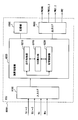
- FIG. 1 is an overall block diagram of a vehicle including a control device according to an embodiment of the present invention. It is a figure which shows the relationship between the voltage control range at the time of EV driving
- 1 power system 2 driving force generator, 10-1 to 10-3 power storage device, 11 charging device, 12-1, 12-2 converter, 13 connector, 14-1 to 14-3 current sensor, 15 paddle, 16 -1 to 16-3, 20 voltage sensor, 17 HV switch, 18-1, 18-2 switching device, 19 AC power supply, 22 converter ECU, 30-1, 30-2 inverter, 32-1, 32-2 MG , 34 Power split device, 36 engine, 38 drive wheel, 100 vehicle, 8000 ECU, 8100 input interface, 8200 arithmetic processing unit, 8210 travel control unit, 8220 SOC calculation unit, 8230 switching control unit, 8300 storage unit, 8400 output interface , MPL main positive bus, MNL main negative bus, C smoothing control Capacitors, RY1, RY2, RY3 system relay.
- FIG. 1 is an overall block diagram of a vehicle provided with a control device according to an embodiment of the present invention.
- vehicle 100 includes a power supply system 1, a driving force generation unit 2, and an ECU (Electronic Control Unit) 8000.
- ECU Electronic Control Unit
- the driving force generator 2 includes a first inverter 30-1, a second inverter 30-2, a first MG (Motor-Generator) 32-1, a second MG 32-2, a power split device 34, an engine 36, Drive wheel 38.
- MG Motor-Generator
- the first MG 32-1, the second MG 32-2, and the engine 36 are connected to the power split device 34.
- the vehicle 100 travels by driving force from at least one of the engine 36 and the second MG 32-2. More specifically, vehicle 100 travels in any one of an electric travel mode (hereinafter also referred to as “EV travel mode”) and a hybrid travel mode (hereinafter also referred to as “HV travel mode”).
- EV travel mode is a travel mode in which the vehicle 100 travels with the power of the second MG 32-2 without using the power of the engine 36.
- the HV travel mode is a travel mode in which the vehicle 100 travels with the power of the engine 36 and the second MG 32-2.
- the ECU 8000 performs either EV traveling control for traveling the vehicle 100 in the EV traveling mode or HV traveling control for traveling the vehicle 100 in the HV traveling mode.
- the power generated by the engine 36 is divided into two paths by the power split device 34. That is, one is a path transmitted to the drive wheel 38 and the other is a path transmitted to the first MG 32-1.
- Each of the first MG 32-1 and the second MG 32-2 is an AC rotating electric machine, for example, a three-phase AC rotating electric machine including a rotor in which a permanent magnet is embedded.
- SOC State Of Charge
- a predetermined range for example, about 40% to 60%.
- the engine 36 is operated, and power is generated by the first MG 32-1 using the power of the engine 36 divided by the power split device 34.
- the electric power generated by the first MG 32-1 is supplied to the power supply system 1.
- the second MG 32-2 generates driving force using at least one of the power supplied from the power supply system 1 and the power generated by the first MG 32-1. Then, the driving force of the second MG 32-2 is transmitted to the driving wheel 38.
- the second MG 32-2 is driven by the drive wheel 38, and the second MG 32-2 operates as a generator.
- second MG 32-2 operates as a regenerative brake that converts braking energy into electric power. Then, the electric power generated by the second MG 32-2 is supplied to the power supply system 1.
- the power split device 34 includes a planetary gear including a sun gear, a pinion gear, a carrier, and a ring gear.
- the pinion gear engages with the sun gear and the ring gear.
- the carrier supports the pinion gear so as to be capable of rotating, and is connected to the crankshaft of the engine 36.
- the sun gear is connected to the rotation shaft of the first MG 32-1.
- the ring gear is connected to the rotation shaft of the second MG 32-2.
- the first inverter 30-1 and the second inverter 30-2 are connected to the main positive bus MPL and the main negative bus MNL. Then, first inverter 30-1 and second inverter 30-2 convert drive power (DC power) supplied from power supply system 1 into AC power and output the AC power to first MG 32-1 and second MG 32-2, respectively. . The first inverter 30-1 and the second inverter 30-2 convert the AC power generated by the first MG 32-1 and the second MG 32-2, respectively, into DC power and output it as regenerative power to the power supply system 1.
- each of the first inverter 30-1 and the second inverter 30-2 includes, for example, a bridge circuit including switching elements for three phases.
- Each inverter drives a corresponding MG by performing a switching operation in accordance with drive signals PWIV1 and PWIV2 from ECU 8000, respectively.
- ECU 8000 calculates vehicle required power Ps based on detection signals of respective sensors (not shown), travel conditions, accelerator opening, and the like, and torques of first MG 32-1 and second MG 32-2 based on the calculated vehicle required power Ps. A target value and a rotational speed target value are calculated. ECU 8000 controls first inverter 30-1 and second inverter 30-2 so that the generated torque and rotation speed of first MG 32-1 and second MG 32-2 become target values.
- the power supply system 1 includes a first power storage device 10-1, a second power storage device 10-2, a third power storage device 10-3, a first converter 12-1, a second converter 12-2, Switching device 18-1, second switching device 18-2, main positive bus MPL, main negative bus MNL, smoothing capacitor C, current sensors 14-1 to 14-3, voltage sensors 16-1 to 16-3, 20, charging device 11, and connector 13.
- the charging device 11 converts electric power from an AC power supply 19 of an electric power company provided outside the vehicle into direct current, and the first power storage device 10-1, the second power storage device 10-2, and the third power storage device 10-3. Output to.
- the ECU 8000 includes the first power storage device 10-1, the second power storage device 10-2, and the third power storage device 10-3.
- the charging device 11 is controlled such that SOCm, SOCs1, and SOCs2, which are values indicating the respective charging states, become upper limit values (for example, about 80%).
- vehicle 100 is a vehicle capable of traveling with electric power supplied from a power source outside the vehicle (hereinafter also referred to as “plug-in vehicle”).
- the vehicle to which the control device according to the present invention is applicable is not limited to a plug-in vehicle.
- Each of the first power storage device 10-1, the second power storage device 10-2, and the third power storage device 10-3 is a DC power source in which a plurality of battery cells such as nickel hydride and lithium ion are connected in series.
- the output voltages of first power storage device 10-1, second power storage device 10-2, and third power storage device 10-3 are adjusted by the number of battery cells provided therein.
- the output voltage (number of battery cells) of each power storage device will be described later.
- any of first power storage device 10-1, second power storage device 10-2, and third power storage device 10-3 may be a rechargeable large-capacity capacitor, for example.
- the first power storage device 10-1 is connected to the first converter 12-1, and the second power storage device 10-2 and the third power storage device 10-3 are connected to the second switching device 18-2.
- First switching device 18-1 is provided between first power storage device 10-1 and first converter 12-1, and in accordance with switching signal SW1 from ECU 8000, first power storage device 10-1 and first converter 12 are connected. Switches the electrical connection state with -1. More specifically, the first switching device 18-1 includes a system relay RY1. When the switching signal SW1 is deactivated, the system relay RY1 is turned on. When the switching signal SW1 is activated, the system relay RY1 is turned on. The switching signal SW1 is activated when an unillustrated ignition switch is turned on by the user. That is, system relay RY1 is kept on when vehicle 100 is traveling.
- Second switching device 18-2 is provided between second power storage device 10-2 and third power storage device 10-3 and second converter 12-2, and in accordance with switching signal SW2 from ECU 8000, second power storage device The electrical connection state between the second converter 12-2 and the second power storage device 10-3 is switched. More specifically, the second switching device 18-2 includes system relays RY2 and RY3. System relay RY2 is arranged between second power storage device 10-2 and second converter 12-2. System relay RY3 is arranged between third power storage device 10-3 and second converter 12-2. ECU 8000 generates switching signal SW2 for controlling on / off of each of system relays RY2 and RY3, and outputs the switching signal SW2 to second switching device 18-2.
- the first converter 12-1 and the second converter 12-2 are connected in parallel to the main positive bus MPL and the main negative bus MNL.
- First converter 12-1 performs voltage conversion between first power storage device 10-1 and main positive bus MPL and main negative bus MNL based on drive signal PWC1 from ECU 8000.
- Smoothing capacitor C is connected between main positive bus MPL and main negative bus MNL, and reduces power fluctuation components included in main positive bus MPL and main negative bus MNL.
- Voltage sensor 20 detects voltage Vh between main positive bus MPL and main negative bus MNL, and outputs the detected value to ECU 8000.
- the voltage Vh is a voltage input to the first inverter 30-1 and the second inverter 30-2.
- this voltage Vh is also referred to as “system voltage Vh”.
- Current sensors 14-1 to 14-3 include current Ib1 input / output to / from first power storage device 10-1, current Ib2 input / output to / from second power storage device 10-2, and third power storage device. Current Ib3 input / output to / from 10-3 is detected, and the detected value is output to ECU 8000.
- Each of current sensors 14-1 to 14-3 detects a current (discharge current) output from the corresponding power storage device as a positive value and a current (charge current) input to the corresponding power storage device as a negative value. Detect as. FIG. 1 shows the case where each of the current sensors 14-1 to 14-3 detects the current of the positive line, but each of the current sensors 14-1 to 14-3 detects the current of the negative line. May be.
- Voltage sensors 16-1 to 16-3 detect voltage Vb1 of first power storage device 10-1, voltage Vb2 of second power storage device 10-2, and voltage Vb3 of third power storage device 10-3, respectively. The detected value is output to ECU 8000.
- the ECU 8000 determines the first converter 12-1 and the second converter 12 based on the detected values from the current sensors 14-1 to 14-3 and the voltage sensors 16-1 to 16-3, 20 and the vehicle required power Ps.
- Drive signals PWC1 and PWC2 for driving -2 respectively
- ECU 8000 uses the generated drive signals PWC1, PWC2, PWIV1, PWIV2, and PWENG as the first converter 12-1, the second converter 12-2, the first inverter 30-1, the second inverter 30-2, Output to the engine 36.
- ECU 8000 is a first power storage device 10-1 connected to first converter 12-1 in a discharge mode in which power is supplied from power supply system 1 to driving force generation unit 2 (that is, vehicle required power Ps> 0). Between the discharge margin power amount of the second power storage device 10-2 and the third power storage device 10-3 connectable to the second converter 12-2 by the second switching device 18-2 Accordingly, a discharge distribution ratio indicating the distribution of power discharged from the first power storage device 10-1 and the power storage device electrically connected to the second converter 12-2 by the second switching device 18-2 is calculated. To do. ECU 8000 controls first converter 12-1 and second converter 12-2 in accordance with the calculated discharge distribution ratio.
- ECU 8000 in the charging mode in which electric power is supplied from driving force generating unit 2 to power supply system 1 (that is, vehicle required power Ps ⁇ 0), the amount of remaining charging power of first power storage device 10-1 and the second switching Connected to the first power storage device 10-1 and the second converter 12-2 according to the ratio of the charge margin power amount of the power storage device electrically connected to the second converter 12-2 by the device 18-2 A charge distribution ratio indicating distribution of electric power charged to the power storage device is calculated. ECU 8000 controls first converter 12-1 and second converter 12-2 in accordance with the calculated charge distribution ratio.
- the vehicle 100 is provided with an HV switch 17.
- the HV switch 17 is a switch for the driver to input an HV request indicating that HV traveling is requested.
- the HV switch 17 When the HV switch 17 is turned on by the driver, the HV switch 17 outputs an HV request signal Rhv to the ECU 8000.
- ECU 8000 executes any travel control of EV travel control and HV travel control based on vehicle required power Ps, SOC of each power source, HV request signal Rhv from HV switch 17, and the like.
- each MG During HV running control, power generation, regeneration, and motor output by each MG are controlled so that the SOC of each power source is included in a predetermined range. For example, as described above, the ECU 8000 increases the amount of power generated by each MG by starting the stopped engine 36 or increasing the output of the operating engine 36 when each power supply needs to be charged. Increase the amount of charge for each power supply.
- ECU 8000 controls system voltage Vh and each MG by controlling at least one of first converter 12-1 and second converter 12-2 in both HV traveling control and EV traveling control. Is adjusted to a value included in the optimum voltage range (hereinafter also simply referred to as “voltage control range”).
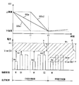
- FIG. 2 shows the relationship between the voltage control range described above and the output voltage of each power storage device.
- first power storage device 10-1 is “master power source”
- second power storage device 10-2 is “first slave power source”
- third power storage device 10-3 is “second slave power source”. Also called.
- the voltage control range ⁇ during EV travel control is a range from the lower limit value Vlow (EV) to the upper limit value Vhi.
- the voltage control range ⁇ during HV traveling control is a range from the lower limit value Vlow (HV) to the upper limit value Vhi.
- the lower limit value Vlow (EV) is higher than the lower limit value Vlow (HV).
- the upper limit value Vhi may be about 650 volts
- the lower limit value Vlow (EV) may be about 500 volts
- the lower limit value Vlow (HV) may be about 200 volts.
- ECU 8000 includes first converter 12-1 and second converter 12-2 so that system voltage Vh is included in voltage control range ⁇ during EV travel control, and system voltage Vh is included in voltage control range ⁇ during HV travel control. Control at least one of the following.
- the output voltage Vm of the master power source (first power storage device 10-1) is set to the lower limit value Vlow (HV) of the voltage control range ⁇ during HV running control.
- the output voltage Vs1 of the first slave power supply (second power storage device 10-2) and the output voltage Vs2 of the second slave power supply (third power storage device 10-3) are the lower limit value Vlow (HV) and the lower limit value Vlow ( EV).
- the distribution of the battery cells of the master power supply, the first slave power supply, and the second slave power supply for realizing such an output voltage will be described below.
- total number of required cells When the number of battery cells (hereinafter also referred to as “total number of required cells”) necessary for realizing a predetermined target travelable distance by EV travel is N, first, the output voltage Vm of the master power supply is set to the lower limit value Vlow ( HV), the number Nm of battery cells of the master power source is determined. Next, the remaining (N ⁇ Nm) battery cells obtained by subtracting the number Nm of battery cells of the master power source from the necessary total number N are distributed to the first slave power source and the second slave power source. In this embodiment, the remaining (N ⁇ Nm) battery cells are equally distributed to the first slave power source and the second slave power source.
- the output voltage of one battery cell is about 3.6 volts
- the total number of required cells N is 288, and the lower limit value Vlow (HV) is about 200 volts
- the number of battery cells Nm of the master power supply is 56, 116 battery cells are distributed to the first slave power supply and the second slave power supply, respectively.
- Vm about 201 volts
- the voltage value Vave indicated by the one-dot chain line in FIG. 2 indicates the output voltage of each power supply when the required total number N of cells is evenly distributed among the three power supplies of the master power supply, the first slave power supply, and the second slave power supply. .
- FIG. 3 shows a functional block diagram of the ECU 8000 which is a vehicle control apparatus according to this embodiment.
- ECU 8000 includes an input interface 8100, a calculation processing unit 8200, a storage unit 8300, and an output interface 8400.
- the input interface 8100 receives the detection results of each sensor and transmits them to the arithmetic processing unit 8200.
- the storage unit 8300 stores various types of information, programs, threshold values, maps, and the like, and data is read from or stored in the arithmetic processing unit 8200 as necessary.
- the arithmetic processing unit 8200 includes a travel control unit 8210, an SOC calculation unit 8220, and a switching control unit 8230.
- the traveling control unit 8210 executes any traveling control of EV traveling control and HV traveling control based on the SOC of each power source, the HV request signal Rhv, and the like. Travel control unit 8210 executes EV travel control when either SOCs1 of the first slave power supply or SOCs2 of the second slave power supply exceeds a predetermined threshold (for example, 20%), and the first slave power supply When both SOCs1 and SOCs2 of the second slave power supply drop below the threshold value, HV running control is executed. In addition, when the HV request signal Rhv is received during EV traveling control, traveling control unit 8210 stops EV traveling control and forcibly executes HV traveling control. In the following description, the HV traveling control executed based on the HV request signal Rhv is also referred to as “forced HV traveling control” in order to distinguish it from normal HV traveling control.
- traveling control unit 8210 switches the control range of the system voltage Vh according to the traveling control to be executed. That is, traveling control unit 8210 includes first converter 12 so that system voltage Vh is included in voltage control range ⁇ described above during EV traveling control, and system voltage Vh is included in voltage control range ⁇ described above during HV traveling control. -1 and / or the second converter 12-2 is controlled.
- the traveling control unit 8210 generates drive signals PWC1, PWC2, PWIV1, PWIV2, and PWENG that realize these controls, and the first converter 12-1, the second converter 12-2, the first inverter 30-1, 2 Output to the inverter 30-2 and the engine 36 via the output interface 8400.
- the SOC calculation unit 8220 is configured to use the SOCm of the master power supply, the SOCs1 of the first slave power supply, the second Calculate SOCs2 of the slave power supply.
- the switching control unit 8230 generates a switching signal SW2 for switching an electrical connection state between the first slave power source and the second slave power source and the second converter 12-2 based on the travel control to be executed, the SOC of each power source, and the like. And output to the second switching device 18-2 via the output interface 8400.
- the switching control unit 8230 connects the first slave power supply and disconnects the second slave power supply (turns on the system relay RY2 and turns on the system relay RY3.
- the switching signal SW2 is generated so as to be turned off.
- the switching control unit 8230 disconnects the first slave power supply and turns off the second slave power supply.
- the switching signal SW2 is generated so as to be connected (the system relay RY2 is turned off and the system relay RY3 is turned on).
- the switching control unit 8230 disconnects both the first slave power supply and the second slave power supply (system relays RY2, RY3).
- the switching signal SW2 is generated so that both are turned off.
- the switching control unit 8230 switches the switching signal for disconnecting both the first slave power supply and the second slave power supply. Instead of generating SW2, the switching signal SW2 at the time when the HV request signal Rhv is received is maintained as it is.
- the functions described above may be realized by software or hardware.
- the above-described function is realized by software, specifically, when the CPU that is the arithmetic processing unit 8200 executes the program stored in the storage unit 8300, the above-described function is realized. Will be described.
- step (hereinafter, step is abbreviated as S) 100 ECU 8000 determines whether or not SOCs1 of the first slave power source exceeds a threshold value. If SOCs1 exceeds the threshold value (YES in S100), the process proceeds to S102. Otherwise (NO in S100), the process proceeds to S104.
- ECU 8000 In S102, ECU 8000 generates a switching signal SW2 for connecting the first slave power source and disconnecting the second slave power source, and outputs the switching signal SW2 to second switching device 18-2. As a result, the master power supply and the first slave power supply are connected to each inverter.
- ECU 8000 determines whether or not SOCs2 of the second slave power supply exceeds a threshold value. If SOCs2 exceeds the threshold value (YES in S104), the process proceeds to S106. Otherwise (NO in S104), the process proceeds to S108.
- ECU 8000 In S106, ECU 8000 generates a switching signal SW2 for disconnecting the first slave power source and connecting the second slave power source, and outputs the switching signal SW2 to second switching device 18-2. As a result, the master power source and the second slave power source are connected to each inverter.
- ECU 8000 executes EV traveling control.
- first converter 12-1 and second converter 12-2 are controlled so that system voltage Vh is included in voltage control range ⁇ described above. More specifically, ECU 8000 controls system voltage Vh to lower limit value Vlow (EV) of voltage control range ⁇ , and raises system voltage Vh within voltage control range ⁇ as necessary.
- Vh system voltage
- Vlow EV
- ECU 8000 determines whether or not HV switch 17 is turned on by the driver during EV traveling control (whether or not HV request signal Rhv is received). If HV switch 17 is turned on (YES in S110), the process proceeds to S112. Otherwise (NO in S110), this process ends.
- ECU 8000 executes forced HV traveling control.
- forced HV traveling control the switching signal SW2 when the HV request signal Rhv is received is maintained as it is.
- ECU 8000 In S114, ECU 8000 generates a switching signal SW2 for disconnecting both the first slave power supply and the second slave power supply, and outputs it to second switching device 18-2. Thereby, only the master power supply is connected to each inverter.
- ECU 8000 executes HV traveling control.
- the first converter 12-1 is controlled so that the system voltage Vh is included in the voltage control range ⁇ described above. More specifically, ECU 8000 controls system voltage Vh to lower limit value Vlow (HV) of voltage control range ⁇ , and raises system voltage Vh within voltage control range ⁇ as necessary.
- HV lower limit value
- ECU 8000 which is the control device according to the present embodiment, based on the above-described structure and flowchart will be described.
- FIG. 5 shows the SOC of each power source, the travel control to be executed, and the connection state of each power source when the vehicle is continuously driven after the SOC of each power source is charged to an upper limit value (for example, a value of about 80%). It is a timing chart which shows.
- the system relay RY1 When the vehicle 100 is running (when the ignition is on), the system relay RY1 is kept on, so that the power source of the master is always connected to each inverter via the first converter 12-1.
- EV traveling control is executed in a state where the first slave power source is connected to second converter 12-2 (S102) ( S108). Therefore, until the time t1 when SOCs1 falls to the threshold value, EV running control is performed with the power of the master power supply and the first slave power supply.
- charging / discharging of the master power supply is controlled so that the SOCm of the master power supply also becomes the lower limit value at the timing when the SOCs2 of the second slave power supply becomes the lower limit value.
- EV traveling control is performed until the SOC of each power source reaches the lower limit value.
- the total number of battery cells provided in each power supply is the required total number N. Therefore, a predetermined target travelable distance can be realized by EV travel.
- the lower limit value Vlow (EV) of the voltage control range ⁇ during EV traveling control is higher than the output voltage Vm of the master power supply, the output voltage Vs1 of the first slave power supply, and the output voltage Vs2 of the second slave power supply. Therefore, as shown by the arrows in FIG. 5, during EV traveling control, Vm, Vs1, and Vs2 are boosted to at least the lower limit value Vlow (EV) by the first converter 12-1 and the second converter 12-2, respectively. .
- both the first slave power supply and the second slave power supply are disconnected from second converter 12-2 (S114), and the EV running control is started from HV. Switching to traveling control is performed (S116). Therefore, after time t2, HV traveling control is performed only by the master power source.
- the output voltage of the master power source becomes Vave shown in FIG. 5, and the lower limit value Vlow (HV) of the voltage control range ⁇ during HV traveling control. Will be exceeded. Therefore, the system voltage Vh at the time of HV traveling control becomes unnecessarily high, and the optimum voltage setting is not achieved.
- the master power source is used for the HV running control, and the output voltage Vm of the master power source out of the necessary N cells in total is the lower limit value Vlow (HV) of the voltage control range ⁇ during the HV running control.
- Nm battery cells are distributed to the master power source, and the remaining (N ⁇ Nm) battery cells are evenly distributed to the first slave power source and the second slave power source.
- the system voltage Vh during the HV running control becomes the lower limit value Vlow (HV) without performing the boosting operation by the first converter 12-1. Therefore, power loss due to boosting can be reduced. Furthermore, it is possible to reduce power consumption by suppressing the system voltage Vh from becoming unnecessarily high as compared to the case where the necessary total number N of cells is evenly distributed among the power sources.
- forced HV traveling control is executed (S112).
- the connection state with each power source is maintained at the time when the HV switch 17 is turned on (when the HV request signal Rhv is received). Therefore, it is possible to run while maintaining the SOC of the main power supply and the slave power supply within a predetermined range.
- Such traveling is effective when the driver wants to maintain the power for some reason, for example, when the power of each power source is required after arrival at the destination.
- the control device only the master power source is connected to the MG at the time of HV traveling control, and the output voltage of the master power source among the necessary number of cells is the voltage at the time of HV traveling control.
- the number of battery cells to be the lower limit value of the control range is distributed to the master power source, and the remaining number of battery cells is evenly distributed to the remaining slave power sources.
- the present invention can also be applied to a hybrid vehicle including three or more slave power supplies.
Abstract
Description
Claims (10)
- 内燃機関(36)および回転電機(32-2)の少なくともいずれかを動力源とするハイブリッド車両の制御装置であって、
前記回転電機(32-2)に接続され、前記回転電機(32-2)と電力を授受可能な主電源(10-1)と、
前記回転電機(32-2)と電力を授受可能な複数の副電源(10-2、10-3)と、
前記複数の副電源(10-2、10-3)と前記回転電機(32-2)との間に設けられ、与えられる指令に従って前記複数の副電源(10-2、10-3)のいずれか1つを前記回転電機(32-2)に接続可能に構成された切替装置(18-2)と、
前記切替装置(18-2)を制御する切替制御部(8230)と、
前記内燃機関(36)および前記回転電機(32-2)の少なくともいずれかの動力で前記ハイブリッド車両を走行させるハイブリッド走行制御、および前記内燃機関(36)を用いずに前記回転電機(32-2)の動力で前記ハイブリッド車両を走行させる電気走行制御のいずれかの走行制御を実行する走行制御部(8210)とを含み、
前記切替制御部(8230)は、前記ハイブリッド走行制御中は、前記電気走行制御中よりも、前記回転電機(32-2)に接続される前記複数の副電源(10-2、10-3)の数が少なくなるように、前記切替装置を制御する、ハイブリッド車両の制御装置。 - 前記切替制御部(8230)は、前記電気走行制御中は、前記複数の副電源(10-2、10-3)のいずれか1つを前記回転電気に接続し、前記ハイブリッド走行制御中は、前記複数の副電源(10-2、10-3)を前記回転電機(32-2)から切り離す、請求の範囲第1項に記載のハイブリッド車両の制御装置。
- 前記切替制御部(8230)は、前記電気走行制御中である場合に、前記複数の副電源(10-2、10-3)のうち前記回転電機(32-2)に接続された第1の副電源(10-2)の充電状態が所定状態よりも低下したとき、前記第1の副電源(10-2)を前記回転電機(32-2)から切り離して他の第2の副電源(10-3)を前記回転電機(32-2)に接続する、請求の範囲第1または2項に記載のハイブリッド車両の制御装置。
- 前記走行制御部(8210)は、前記複数の副電源(10-2、10-3)のすべての充電状態が前記所定状態よりも低下した場合、前記電気走行制御に代えて前記ハイブリッド走行制御を実行する、請求の範囲第3項に記載のハイブリッド車両の制御装置。
- 前記制御装置は、前記ハイブリッド走行制御での走行を要求していることを示すハイブリッド走行走行要求を運転者が入力する入力部(17)をさらに含み、
前記走行制御部(8210)は、前記電気走行制御中に前記ハイブリッド走行要求が入力された場合、前記電気走行制御を停止して前記ハイブリッド走行制御を強制的に実行し、
前記切替制御部(8230)は、前記ハイブリッド走行要求が入力されたことに応じて前記ハイブリッド走行制御が強制的に実行される場合は、前記ハイブリッド走行要求が入力された時点における前記回転電機(32-2)と前記複数の副電源(10-2、10-3)のいずれか1つとの接続状態を維持する、請求の範囲第1項に記載のハイブリッド車両の制御装置。 - 前記主電源(10-1)の出力電圧は、前記複数の副電源(10-2、10-3)のいずれの出力電圧よりも低い値に設定される、請求の範囲第1項に記載のハイブリッド車両の制御装置。
- 前記制御装置は、
前記回転電機(32-2)と前記主電源(10-1)との間に設けられ、前記主電源(10-1)の出力電圧を前記回転電機(32-2)の制御電圧範囲に含まれる値に変換して前記回転電機(32-2)に出力する第1のコンバータ(12-1)と、
前記回転電機(32-2)と前記複数の副電源(10-2、10-3)との間に設けられ、前記複数の副電源(10-2、10-3)の出力電圧を前記回転電機(32-2)の制御電圧範囲に含まれる値に変換して前記回転電機(32-2)に出力する第2のコンバータ(12-2)とをさらに含み、
前記ハイブリッド走行制御時における前記回転電機(32-2)の最適制御電圧範囲の第1の下限値は、前記電気走行制御時における前記回転電機(32-2)の制御電圧範囲の第2の下限値よりも低く、
前記主電源(10-1)の出力電圧は、前記第1の下限値に設定され、
前記複数の副電源(10-2、10-3)の出力電圧は、前記第1の下限値と前記第2の下限値の間の値に設定される、請求の範囲第1項に記載のハイブリッド車両の制御装置。 - 前記主電源(10-1)および前記複数の副電源(10-2、10-3)の各々の内部には、直列に接続された複数の電池セルが備えられ、
前記主電源(10-1)および前記複数の副電源(10-2、10-3)の各々は、内部に備えられた電池セルの数に応じた出力電圧を出力し、
前記主電源(10-1)には、前記電気走行制御時の走行可能距離を所定の目標距離以上に確保するために必要な電池セルの総数のうち、前記主電源(10-1)の出力電圧が前記第1の下限値となる数の電池セルが備えられ、
前記複数の副電源(10-2、10-3)には、前記必要な電池セルの総数のうち、前記主電源(10-1)に備えられた数以外の残余の数の電池セルが前記複数の副電源(10-2、10-3)の各々に均等に備えられる、請求の範囲第1項に記載のハイブリッド車両の制御装置。 - 前記ハイブリッド車両は、車両外部の電源(19)からの電力を前記主電源(10-1)および前記複数の副電源(10-2、10-3)に充電可能なプラグインハイブリッド車両である、請求の範囲第1項に記載のハイブリッド車両の制御装置。
- 内燃機関(36)および回転電機(32-2)の少なくともいずれかを動力源とするハイブリッド車両の制御装置(8000)が行なう制御方法であって、前記制御装置(8000)には、前記回転電機(32-2)に接続され、前記回転電機(32-2)と電力を授受可能な主電源(10-1)と、前記回転電機(32-2)と電力を授受可能な複数の副電源(10-2、10-3)と、前記複数の副電源(10-2、10-3)と前記回転電機(32-2)との間に設けられ、与えられる指令に従って前記複数の副電源(10-2、10-3)のいずれか1つを前記回転電機(32-2)に接続可能に構成された切替装置(18-2)とが備えられ、
前記制御方法は、
前記内燃機関(36)および前記回転電機(32-2)の少なくともいずれかの動力で前記ハイブリッド車両を走行させるハイブリッド走行制御、および前記内燃機関(36)を用いずに前記回転電機(32-2)の動力で前記ハイブリッド車両を走行させる電気走行制御のいずれかの走行制御を実行するステップと、
前記ハイブリッド走行制御中は、前記電気走行制御中よりも、前記回転電機(32-2)に接続される前記複数の副電源(10-2、10-3)の数が少なくなるように、前記切替装置を制御するステップとを含む、ハイブリッド車両の制御方法。
Priority Applications (5)
| Application Number | Priority Date | Filing Date | Title |
|---|---|---|---|
| US12/991,959 US8718847B2 (en) | 2008-10-14 | 2008-10-14 | Control apparatus and control method for hybrid vehicle |
| CN2008801315251A CN102186710B (zh) | 2008-10-14 | 2008-10-14 | 混合动力车辆的控制装置和控制方法 |
| JP2010533733A JP4788842B2 (ja) | 2008-10-14 | 2008-10-14 | ハイブリッド車両の制御装置および制御方法 |
| PCT/JP2008/068539 WO2010044132A1 (ja) | 2008-10-14 | 2008-10-14 | ハイブリッド車両の制御装置および制御方法 |
| EP08877392.4A EP2351676B1 (en) | 2008-10-14 | 2008-10-14 | Hybrid vehicle control device and control method |
Applications Claiming Priority (1)
| Application Number | Priority Date | Filing Date | Title |
|---|---|---|---|
| PCT/JP2008/068539 WO2010044132A1 (ja) | 2008-10-14 | 2008-10-14 | ハイブリッド車両の制御装置および制御方法 |
Publications (1)
| Publication Number | Publication Date |
|---|---|
| WO2010044132A1 true WO2010044132A1 (ja) | 2010-04-22 |
Family
ID=42106310
Family Applications (1)
| Application Number | Title | Priority Date | Filing Date |
|---|---|---|---|
| PCT/JP2008/068539 WO2010044132A1 (ja) | 2008-10-14 | 2008-10-14 | ハイブリッド車両の制御装置および制御方法 |
Country Status (5)
| Country | Link |
|---|---|
| US (1) | US8718847B2 (ja) |
| EP (1) | EP2351676B1 (ja) |
| JP (1) | JP4788842B2 (ja) |
| CN (1) | CN102186710B (ja) |
| WO (1) | WO2010044132A1 (ja) |
Cited By (3)
| Publication number | Priority date | Publication date | Assignee | Title |
|---|---|---|---|---|
| JP2013150448A (ja) * | 2012-01-19 | 2013-08-01 | Toyota Motor Corp | 車両および車両の制御方法 |
| JP2013150447A (ja) * | 2012-01-19 | 2013-08-01 | Toyota Motor Corp | 車両および車両の制御方法 |
| EP2671772A4 (en) * | 2011-02-03 | 2018-05-02 | Toyota Jidosha Kabushiki Kaisha | Hybrid vehicle and control method thereof |
Families Citing this family (15)
| Publication number | Priority date | Publication date | Assignee | Title |
|---|---|---|---|---|
| EP2353922A4 (en) | 2008-10-31 | 2017-03-15 | Toyota Jidosha Kabushiki Kaisha | Electromotive vehicle power supply system, electromotive vehicle, and electromotive vehicle control method |
| US8571733B2 (en) * | 2008-10-31 | 2013-10-29 | Toyota Jidosha Kabushiki Kaisha | Hybrid vehicle and method for controlling the same |
| JP5152408B2 (ja) | 2009-06-10 | 2013-02-27 | トヨタ自動車株式会社 | ハイブリッド車両およびその制御方法 |
| US8760115B2 (en) * | 2009-08-20 | 2014-06-24 | GM Global Technology Operations LLC | Method for charging a plug-in electric vehicle |
| WO2011126076A1 (ja) * | 2010-04-09 | 2011-10-13 | 大日本印刷株式会社 | 薄膜トランジスタ基板 |
| JP5998454B2 (ja) * | 2011-11-07 | 2016-09-28 | ソニー株式会社 | 制御装置、制御方法および制御システム |
| BR112014010959B1 (pt) * | 2011-11-08 | 2020-10-20 | Volvo Lastvagnar Ab | método e disposição em um veículo híbrido |
| JP5772784B2 (ja) * | 2012-10-19 | 2015-09-02 | トヨタ自動車株式会社 | 車両、電源システムおよび電源システムの制御方法 |
| US9434378B2 (en) | 2014-12-23 | 2016-09-06 | Toyota Motor Engineering & Manufacturing North America, Inc. | System and method for improving the vehicle feel, fuel efficiency and performance of a hybrid vehicle |
| US10020759B2 (en) * | 2015-08-04 | 2018-07-10 | The Boeing Company | Parallel modular converter architecture for efficient ground electric vehicles |
| JP6348929B2 (ja) * | 2016-05-23 | 2018-06-27 | 本田技研工業株式会社 | 動力システム及び輸送機器、並びに、電力伝送方法 |
| CN107554345A (zh) * | 2017-09-18 | 2018-01-09 | 江西爱驰亿维实业有限公司 | 双源电池包、管理方法和系统以及电动汽车 |
| US11040628B2 (en) * | 2018-02-05 | 2021-06-22 | Hitachi, Ltd. | Method and system for controlling discharge ratio between primary and secondary battery in a vehicle |
| JP6922820B2 (ja) * | 2018-04-13 | 2021-08-18 | トヨタ自動車株式会社 | 電源制御装置 |
| CN109720236A (zh) * | 2018-12-29 | 2019-05-07 | 凯博易控驱动(苏州)股份有限公司 | 双电机动力电源构架、控制系统和控制器 |
Citations (8)
| Publication number | Priority date | Publication date | Assignee | Title |
|---|---|---|---|---|
| JPH08251714A (ja) * | 1995-03-10 | 1996-09-27 | Mitsubishi Motors Corp | 電気自動車の電源装置 |
| JP2003209969A (ja) | 2001-12-06 | 2003-07-25 | General Motors Corp <Gm> | 電動モータ電源管理システム |
| JP2007062639A (ja) * | 2005-09-01 | 2007-03-15 | Toyota Motor Corp | ハイブリッド自動車 |
| JP2007098981A (ja) * | 2005-09-30 | 2007-04-19 | Toyota Motor Corp | 車両用電源装置 |
| JP2007244093A (ja) * | 2006-03-08 | 2007-09-20 | Nissan Motor Co Ltd | 車両用電力供給装置の電力供給制御方法、及び車両用電力供給装置 |
| JP2007269249A (ja) * | 2006-03-31 | 2007-10-18 | Daihatsu Motor Co Ltd | 車両の走行動力切り替え制御方法 |
| JP2007335151A (ja) | 2006-06-13 | 2007-12-27 | Toyota Motor Corp | 燃料電池車両の電力制御装置 |
| JP2008109840A (ja) | 2006-09-28 | 2008-05-08 | Toyota Motor Corp | 電源システムおよびそれを備えた車両、電源システムの制御方法ならびにその制御方法をコンピュータに実行させるためのプログラムを記録したコンピュータ読取可能な記録媒体 |
Family Cites Families (11)
| Publication number | Priority date | Publication date | Assignee | Title |
|---|---|---|---|---|
| JPH08140202A (ja) * | 1994-11-07 | 1996-05-31 | Hitachi Ltd | 電気車用保護装置及び保護方法 |
| JP3682685B2 (ja) * | 1999-03-10 | 2005-08-10 | スズキ株式会社 | 車両推進装置の制御装置 |
| JP2001065437A (ja) * | 1999-08-25 | 2001-03-16 | Honda Motor Co Ltd | ハイブリッド車両の制御装置 |
| JP4479919B2 (ja) * | 2006-03-29 | 2010-06-09 | 株式会社デンソー | 電気自動車の制御装置 |
| JP4501893B2 (ja) * | 2006-04-24 | 2010-07-14 | トヨタ自動車株式会社 | 電源システムおよび車両 |
| CN2936821Y (zh) * | 2006-08-29 | 2007-08-22 | 比亚迪股份有限公司 | 一种混合动力驱动系统 |
| RU2412514C2 (ru) * | 2006-09-29 | 2011-02-20 | Тойота Дзидося Кабусики Кайся | Устройство источника питания и транспортное средство с устройством источника питания |
| US8234025B2 (en) * | 2006-11-28 | 2012-07-31 | GM Global Technology Operations LLC | Control system for a hybrid powertrain system |
| JP4513812B2 (ja) * | 2007-01-04 | 2010-07-28 | トヨタ自動車株式会社 | 車両の電源装置および車両 |
| JP4569603B2 (ja) * | 2007-01-04 | 2010-10-27 | トヨタ自動車株式会社 | 電源システムおよびそれを備える車両、ならびにその制御方法 |
| CN201128379Y (zh) * | 2007-11-23 | 2008-10-08 | 吉林市北华航天科技有限公司 | 车用太阳能-超级电容混合动力电源 |
-
2008
- 2008-10-14 WO PCT/JP2008/068539 patent/WO2010044132A1/ja active Application Filing
- 2008-10-14 JP JP2010533733A patent/JP4788842B2/ja not_active Expired - Fee Related
- 2008-10-14 US US12/991,959 patent/US8718847B2/en active Active
- 2008-10-14 CN CN2008801315251A patent/CN102186710B/zh not_active Expired - Fee Related
- 2008-10-14 EP EP08877392.4A patent/EP2351676B1/en active Active
Patent Citations (8)
| Publication number | Priority date | Publication date | Assignee | Title |
|---|---|---|---|---|
| JPH08251714A (ja) * | 1995-03-10 | 1996-09-27 | Mitsubishi Motors Corp | 電気自動車の電源装置 |
| JP2003209969A (ja) | 2001-12-06 | 2003-07-25 | General Motors Corp <Gm> | 電動モータ電源管理システム |
| JP2007062639A (ja) * | 2005-09-01 | 2007-03-15 | Toyota Motor Corp | ハイブリッド自動車 |
| JP2007098981A (ja) * | 2005-09-30 | 2007-04-19 | Toyota Motor Corp | 車両用電源装置 |
| JP2007244093A (ja) * | 2006-03-08 | 2007-09-20 | Nissan Motor Co Ltd | 車両用電力供給装置の電力供給制御方法、及び車両用電力供給装置 |
| JP2007269249A (ja) * | 2006-03-31 | 2007-10-18 | Daihatsu Motor Co Ltd | 車両の走行動力切り替え制御方法 |
| JP2007335151A (ja) | 2006-06-13 | 2007-12-27 | Toyota Motor Corp | 燃料電池車両の電力制御装置 |
| JP2008109840A (ja) | 2006-09-28 | 2008-05-08 | Toyota Motor Corp | 電源システムおよびそれを備えた車両、電源システムの制御方法ならびにその制御方法をコンピュータに実行させるためのプログラムを記録したコンピュータ読取可能な記録媒体 |
Non-Patent Citations (1)
| Title |
|---|
| See also references of EP2351676A4 |
Cited By (5)
| Publication number | Priority date | Publication date | Assignee | Title |
|---|---|---|---|---|
| EP2671772A4 (en) * | 2011-02-03 | 2018-05-02 | Toyota Jidosha Kabushiki Kaisha | Hybrid vehicle and control method thereof |
| EP3460994A1 (en) * | 2011-02-03 | 2019-03-27 | Toyota Jidosha Kabushiki Kaisha | Hybrid vehicle and control method thereof |
| JP2013150448A (ja) * | 2012-01-19 | 2013-08-01 | Toyota Motor Corp | 車両および車両の制御方法 |
| JP2013150447A (ja) * | 2012-01-19 | 2013-08-01 | Toyota Motor Corp | 車両および車両の制御方法 |
| US8975839B2 (en) | 2012-01-19 | 2015-03-10 | Toyota Jidosha Kabushiki Kaisha | Vehicle, and control method for vehicle |
Also Published As
| Publication number | Publication date |
|---|---|
| JPWO2010044132A1 (ja) | 2012-03-08 |
| EP2351676A4 (en) | 2018-01-24 |
| US8718847B2 (en) | 2014-05-06 |
| CN102186710A (zh) | 2011-09-14 |
| US20110066311A1 (en) | 2011-03-17 |
| CN102186710B (zh) | 2013-11-20 |
| JP4788842B2 (ja) | 2011-10-05 |
| EP2351676B1 (en) | 2021-12-22 |
| EP2351676A1 (en) | 2011-08-03 |
Similar Documents
| Publication | Publication Date | Title |
|---|---|---|
| JP4788842B2 (ja) | ハイブリッド車両の制御装置および制御方法 | |
| US8742718B2 (en) | Charging apparatus for vehicle | |
| EP2353920B1 (en) | Electrically driven vehicle and electrically driven vehicle control method | |
| US8594873B2 (en) | Power supply system for electric powered vehicle and control method thereof | |
| JP5621845B2 (ja) | 車両用制御装置および車両用制御方法 | |
| US8502412B2 (en) | Power supply system for vehicle and electrically-powered vehicle having the power supply system | |
| WO2010050038A1 (ja) | 電動車両の電源システムおよびその制御方法 | |
| WO2010050044A1 (ja) | 電動車両の電源システムおよびその制御方法 | |
| WO2010143277A1 (ja) | 電動車両の電源システムおよびその制御方法 | |
| WO2010143280A1 (ja) | 電動車両および電動車両の制御方法 | |
| WO2010128550A1 (ja) | 電源システムおよびそれを備える車両 | |
| JP5245780B2 (ja) | 車両 | |
| EP2403103B1 (en) | Control apparatus and method for vehicle | |
| WO2010050040A1 (ja) | 電動車両の電源システムおよびその制御方法 | |
| US20110068740A1 (en) | Power supply system for vehicle, electric vehicle having the same, and method of controlling power supply system for vehicle | |
| JP4569696B2 (ja) | 電動車両およびその制御方法 | |
| EP2353921B1 (en) | Vehicle control device and control method | |
| WO2008133154A1 (ja) | 電気機器および電気機器の制御方法 | |
| JP2010115050A (ja) | 車両の電源システム | |
| US10569656B2 (en) | Regenerative control device | |
| JP2010089719A (ja) | ハイブリッド車両の電源システム | |
| JP6665582B2 (ja) | ハイブリッド車両 | |
| JP2011223719A (ja) | 電源装置 | |
| WO2010089888A1 (ja) | 電源システム | |
| JP2023067409A (ja) | ハイブリッド車両 |
Legal Events
| Date | Code | Title | Description |
|---|---|---|---|
| WWE | Wipo information: entry into national phase |
Ref document number: 200880131525.1 Country of ref document: CN |
|
| 121 | Ep: the epo has been informed by wipo that ep was designated in this application |
Ref document number: 08877392 Country of ref document: EP Kind code of ref document: A1 |
|
| WWE | Wipo information: entry into national phase |
Ref document number: 12991959 Country of ref document: US |
|
| WWE | Wipo information: entry into national phase |
Ref document number: 2010533733 Country of ref document: JP |
|
| NENP | Non-entry into the national phase |
Ref country code: DE |
|
| WWE | Wipo information: entry into national phase |
Ref document number: 2008877392 Country of ref document: EP |