WO2010035673A1 - 高純度塩素の製造方法 - Google Patents
高純度塩素の製造方法 Download PDFInfo
- Publication number
- WO2010035673A1 WO2010035673A1 PCT/JP2009/066189 JP2009066189W WO2010035673A1 WO 2010035673 A1 WO2010035673 A1 WO 2010035673A1 JP 2009066189 W JP2009066189 W JP 2009066189W WO 2010035673 A1 WO2010035673 A1 WO 2010035673A1
- Authority
- WO
- WIPO (PCT)
- Prior art keywords
- chlorine
- zeolite
- cylinder
- oxygen gas
- liquefied chlorine
- Prior art date
- Legal status (The legal status is an assumption and is not a legal conclusion. Google has not performed a legal analysis and makes no representation as to the accuracy of the status listed.)
- Ceased
Links
Images

Classifications
-
- C—CHEMISTRY; METALLURGY
- C01—INORGANIC CHEMISTRY
- C01B—NON-METALLIC ELEMENTS; COMPOUNDS THEREOF; METALLOIDS OR COMPOUNDS THEREOF NOT COVERED BY SUBCLASS C01C
- C01B7/00—Halogens; Halogen acids
- C01B7/01—Chlorine; Hydrogen chloride
- C01B7/07—Purification ; Separation
- C01B7/075—Purification ; Separation of liquid chlorine
-
- B—PERFORMING OPERATIONS; TRANSPORTING
- B01—PHYSICAL OR CHEMICAL PROCESSES OR APPARATUS IN GENERAL
- B01D—SEPARATION
- B01D15/00—Separating processes involving the treatment of liquids with solid sorbents; Apparatus therefor
- B01D15/08—Selective adsorption, e.g. chromatography
-
- C—CHEMISTRY; METALLURGY
- C01—INORGANIC CHEMISTRY
- C01B—NON-METALLIC ELEMENTS; COMPOUNDS THEREOF; METALLOIDS OR COMPOUNDS THEREOF NOT COVERED BY SUBCLASS C01C
- C01B7/00—Halogens; Halogen acids
- C01B7/01—Chlorine; Hydrogen chloride
Definitions
- the present invention relates to a method for producing high purity chlorine. More specifically, the present invention relates to a method for producing high-purity chlorine that can suppress generation of oxygen gas, which is an impurity, after filling liquefied chlorine in a cylinder. High-purity chlorine produced by this production method is used for dry etching and cleaning performed in the production of semiconductor elements such as VLSI, optical fibers, and liquid crystal display panels.
- Patent Document 1 describes the removal of oxygen in liquefied chlorine, but there is no examination or suggestion that oxygen is generated after the removal.
- Patent Document 2 describes the removal of impurities such as moisture by zeolite, but oxygen is not described, and the possibility that impurities are generated again by subsequent storage is also discussed. There is no suggestion.
- Patent Document 2 describes the removal of impurities from liquid nitrogen and liquid helium, but does not describe liquid chlorine.
- JP 2002-316804 A Japanese Patent Laid-Open No. 03-59385 Japanese Patent Laid-Open No. 04-367504 JP 05-155603 A
- the present invention solves the above-mentioned conventional problems, and provides a method for producing high-purity chlorine that can suppress generation of oxygen gas as an impurity after filling a cylinder with liquefied chlorine. Objective.
- the present invention is as follows. 1. A method for producing high-purity chlorine, characterized in that liquefied chlorine is brought into contact with zeolite, purified liquefied chlorine obtained by the contact is filled in a cylinder, and generation of oxygen gas in the cylinder is suppressed. 2.
- the liquefied chlorine before being brought into contact with the zeolite is obtained by liquefying chlorine gas obtained by electrolyzing a salt solution. (1) Thereafter, rectification is performed to separate a non-condensable gas, followed by rectification. The high boiling point impurities are separated and then contacted with the zeolite and then filled into the cylinder, or (2) is then contacted with the zeolite to obtain the purified liquefied chlorine, which is then purified. 2.
- the method for producing high-purity chlorine according to 1 above wherein the non-condensable gas is separated and then rectified to separate impurities of high-boiling components, and then charged into the cylinder. 3.
- the concentration of the oxygen gas contained in the purified liquefied chlorine 25 days after contact with the zeolite was 0.01 to 1.5 vol. 3.
- the concentration of the oxygen gas contained in the purified liquefied chlorine 25 days after contact with the zeolite is 0.01 to 1.0 vol. 5.
- the ratio (X 1 ) of the oxygen gas concentration contained in the liquefied chlorine between 25 days and 1 day after filling the cylinder without contacting the liquefied chlorine with the zeolite is 2.3 to 6.
- the ratio (X 2 ) of the concentration of oxygen gas contained in the purified liquefied chlorine between 25 days and 1 day after filling the cylinder with the purified liquefied chlorine is 1.0 to 2.1.
- the generation of oxygen gas in the cylinder is suppressed by bringing the liquefied chlorine into contact with the zeolite and filling the cylinder with the purified liquefied chlorine obtained by the contact. be able to.
- liquefaction that can suppress the generation of impurities such as oxygen gas even if high purity chlorine is filled in a conventional cylinder and can maintain purity over a long period of time.
- Chlorine can be produced.
- it is purification by contact it is not necessary to perform an intermittent operation like purification by adsorption and release, and continuous production can be performed.
- the liquefied chlorine before contacting with the zeolite is obtained by liquefying chlorine gas obtained by electrolyzing the salt solution.
- the liquefied chlorine obtained thereafter is rectified to separate the non-condensable gas. And then rectified to separate impurities of high-boiling components, and then contacted with zeolite, and then the purified liquefied chlorine obtained by the contact is filled in the cylinder, or (2) the purified liquefaction is then contacted with zeolite. If chlorine is obtained, then purified liquefied chlorine is rectified to separate non-condensable gases, then rectified to separate impurities of high boiling components, and then charged to the cylinder, oxygen in the cylinder The effect of suppressing gas generation can be obtained.
- (1) by performing rectification before the contact step with zeolite, it is possible to suppress the mixing of the zeolite powder to be contacted into the cylinder by the rectification treatment. Furthermore, in (2), it is easy to exchange the used zeolite by performing rectification between the contact step with the zeolite and the cylinder filling step.
- the purity of high-purity chlorine should be maintained over a long period in a period sufficient as a normal storage period of 25 days. Can do.
- the effective diameter of the pores of the zeolite is within a predetermined range, the effect of suppressing the generation of oxygen gas in the cylinder can be further enhanced, and the purity of high purity chlorine can be maintained over a long period of time.
- the ratios X 1 , X 2 , and X 2 / X 1 of the oxygen gas concentration contained in the liquefied chlorine and the purified liquefied chlorine are within a predetermined range, X 1 and X 2 depend on contact with zeolite over time.
- oxygen in the cylinder can be obtained in a period sufficient for a normal storage period of 25 days.
- a gas generation suppressing effect can be obtained, and the purity of high-purity chlorine can be maintained over a long period of time.
- the method for producing high-purity chlorine of the present invention is a method for suppressing oxygen gas generation after filling a cylinder, contacting liquefied chlorine with zeolite, filling the cylinder with the contacted chlorine obtained by this contact, It is characterized by suppressing the generation of oxygen gas inside.
- liquefied chlorine can be produced by an arbitrary production method, and for example, it is obtained by electrolyzing a salt solution to obtain chlorine gas, then dehydrating the chlorine gas with sulfuric acid, and then compressing and liquefying the chlorine gas. be able to.
- zeolite is used to adsorb causative substances that are considered to be brought into contact with liquefied chlorine to generate oxygen gas in the liquefied chlorine, and both natural products and synthetic products can be used.
- the shape of the zeolite can be arbitrarily selected, and examples thereof include pellets, beads, plates, rods, and tubes. Further, zeolite has a structure in which a large number of pores are formed.
- synthetic zeolite such as molecular sieve 3A, molecular sieve 4A, molecular sieve 5A and molecular sieve 13X, and mixtures thereof can be mentioned.
- the molecular sieve 4A, the molecular sieve 5A, the molecular sieve 13X, and a mixture thereof can be exemplified.
- molecular sieve 5A, molecular sieve 13X, and a mixture thereof can be exemplified.
- the maximum effective diameter is preferably 10 nm or less.
- the above “cylinder” is a container for storing purified liquefied chlorine purified by bringing liquefied chlorine into contact with zeolite. Purified liquefied chlorine can be shipped in a state of being filled in a cylinder.
- the material of the cylinder can be arbitrarily selected, and examples thereof include metal such as steel such as steel and stainless steel. Among these, iron cylinders can be a good example because they are inexpensive and widely used.
- the contact condition between the zeolite and the liquefied chlorine can be appropriately selected depending on conditions such as rectification.
- SV superficial velocity
- SV 0.1 to 50 [1 / hour] (preferably 1 to 25 [1 / hour]) Is preferred. This is because if the SV is too large, the effect of suppressing the generation of oxygen gas is reduced, and if the SV is too small, it is necessary to make the removal equipment larger.
- Liquefied chlorine can separate and remove the “non-condensable gas” by rectification.
- This non-condensable gas is an impurity having a lower boiling point than liquefied chlorine such as oxygen and nitrogen.
- the “impurities of high boiling point components” can be separated and removed by rectification.
- the impurities of the high boiling point component are impurities having a boiling point higher than that of liquefied chlorine such as bromine and metal.
- the liquefied chlorine before contacting with the zeolite is liquefied chlorine gas obtained by electrolyzing the salt solution, and then the liquefied product is rectified to separate the non-condensable gas. Subsequently, the rectified product is further rectified to obtain impurities having a high boiling point component. Furthermore, as illustrated in FIG. 2, the purified liquefied chlorine is rectified to separate non-condensable gas after contacting the zeolite and before filling the cylinder, and then the rectified product is further rectified. Thus, impurities having a high boiling point component can be separated and obtained.
- the contact treatment between zeolite and liquefied chlorine is performed before or after the rectification step, the effect of suppressing the generation of oxygen gas in the cylinder can be obtained. Further, when it is carried out before rectification, even if the zeolite powder to be contacted flows out, it is preferable in that the rectification treatment can prevent the powder from being mixed into the cylinder. Moreover, when performing before a cylinder filling after rectification, it is preferable from the point that it is easy to replace
- the concentration of the oxygen gas contained in the purified liquefied chlorine 25 days after contact with the zeolite is, for example, 0.01 to 1.5 vol. ppm (preferably 0.01 to 1.4, more preferably 0.01 to 1.3). Further, for example, 0.01 to 1.0 vol. ppm (preferably 0.01 to 0.9, more preferably 0.01 to 0.8).
- the oxygen gas concentration contained in the gas phase part of the cylinder filled with the purified liquefied chlorine 25 days after contact with the zeolite is, for example, 1 to 220 vol. ppm (preferably 1 to 180, more preferably 1 to 100).
- X 2 / X 1 representing the ratio of suppressing the increase in oxygen gas in the liquefied chlorine compared to the non-contact state due to contact with zeolite can be taken within the range of the values of X 1 and X 2.
- the range is 0.2 to 0.4, and X 1 and X 2 can be values satisfying the range of X 2 / X 1 within the above ranges.
- the effect of suppressing the generation of oxygen gas in the cylinder can be made more than a certain level, and the purity of high purity chlorine can be maintained over a long period of time.
- the concentration of oxygen gas contained in the liquefied chlorine is the concentration of oxygen gas measured in a state where the liquefied chlorine is made into a gas at room temperature.
- X 4 / X 3 representing the ratio of suppressing the increase in oxygen gas in the gas phase of the cylinder compared to the non-contact state due to contact with zeolite is taken within the range of the values of X 4 and X 3.
- the range can be 0.2 to 0.7.
- the effect of suppressing the generation of oxygen gas in the cylinder can be made more than a certain level, and the purity of high purity chlorine can be maintained over a long period of time.
- the analysis was performed by gas chromatography (product name G3900, manufactured by Hitachi, Ltd.) using PID as a detector, 2 m “UniBeads 1S” and 3 m “Molecular Sieve 13XS”, and helium gas as a carrier gas. Performed at ° C.
- the quantitative analysis of oxygen gas is performed on the liquefied chlorine part in the cylinder (hereinafter referred to as the liquid phase part) and the gas phase part in the cylinder, and the concentrations are shown in Table 1 and Table 2, respectively. It was.
- Example 2 purified liquefied chlorine was produced by the same production method as Example 1 except that 13X type synthetic zeolite (“Molecular Sieve 13X”, manufactured by Sakai Kogyo Co., Ltd.) having an effective pore diameter of 1.0 nm was used. And filled into a steel cylinder. Then, the quantitative analysis of oxygen gas was performed by the same method as Example 1. Further, as Comparative Example 1, a steel cylinder was filled without contacting zeolite with the liquefied chlorine raw material.
- 13X type synthetic zeolite (“Molecular Sieve 13X”, manufactured by Sakai Kogyo Co., Ltd.) having an effective pore diameter of 1.0 nm was used. And filled into a steel cylinder. Then, the quantitative analysis of oxygen gas was performed by the same method as Example 1. Further, as Comparative Example 1, a steel cylinder was filled without contacting zeolite with the liquefied chlorine raw material.
- Comparative Example 2 purified liquefied chlorine was obtained by the same production method as in Example 1 except that silica gel having an average pore diameter of 2.5 nm (“Unibeads 1S”, manufactured by GL Sciences Inc.) was used instead of zeolite. The steel cylinder was filled. Then, the quantitative analysis of oxygen gas was performed by the same method as Example 1.
- Oxygen gas concentration in the gas phase part one day after filling the cylinder As shown in Table 2, in Comparative Example 1 in which the oxygen gas concentration in the gas phase part one day after filling the cylinder did not contact the zeolite 92 vol. Example 1 in contact with zeolite was 28 vol. ppm, and Example 2 is 26 vol. It is ppm, and it can be seen that the content of oxygen gas at the time of cylinder filling is smaller than that in Comparative Example 1 as in the liquid phase part. In Comparative Example 2 in which liquefied chlorine was brought into contact with silica gel, the oxygen gas concentration in the gas phase portion was 81 vol. ppm, 28 vol. ppm and 26 vol. It can be seen that the effect of suppressing the oxygen gas content at the time of cylinder filling is smaller than that of ppm.
- Example 1 has a greater effect of suppressing the oxygen gas content than Comparative Example 2.
- Example 2 the oxygen gas concentration is maintained substantially constant in both the liquid phase portion and the gas phase portion, and the generation of oxygen gas in the cylinder is suppressed during a period sufficient as a normal storage period of 25 days. It turns out that an effect can be made more than fixed and purity can be maintained over a long period of time with high purity chlorine. Further, it can be seen that Examples 1 and 2 have a small oxygen gas concentration one day after cylinder filling, although the effective diameter of the pores is smaller than that of Comparative Example 2. In particular, it can be seen that Example 2 having an effective diameter of 1.0 nm has a great effect of suppressing an increase in oxygen gas even when a period of 25 days elapses. This is because, as illustrated in FIG. 3, Comparative Example 2 is a silica gel with a wide pore size distribution, whereas Examples 1 and 2 are molecular sieves (zeolites) with a very narrow pore size distribution. it is conceivable that.
- zeolites molecular sieves
Landscapes
- Chemical & Material Sciences (AREA)
- Organic Chemistry (AREA)
- Inorganic Chemistry (AREA)
- Analytical Chemistry (AREA)
- Chemical Kinetics & Catalysis (AREA)
- Filling Or Discharging Of Gas Storage Vessels (AREA)
- Separation Of Gases By Adsorption (AREA)
- Solid-Sorbent Or Filter-Aiding Compositions (AREA)
- Organic Low-Molecular-Weight Compounds And Preparation Thereof (AREA)
Abstract
Description
液化塩素中の不純物である酸素や窒素等の非凝縮性ガスを除去する方法として、精留による除去方法が開示されている(例えば、特許文献1を参照。)。また、ゼオライトに不純物を吸着させる精製方法も知られている。例えば、液化ヘリウム中に活性炭や合成ゼオライトを接触させて、液化ヘリウム中の微量不純物である水分や炭酸ガスを除去する方法が知られており、特に低温で吸着による除去効果が増すことが開示されている(例えば、特許文献2を参照。)。更に、塩素ガスから酸素等の不純物を除去する方法として、ゼオライトや活性炭に塩素ガスを吸着させた後、導入時とは異なる圧力で吸着している塩素ガスを放出させることによって塩素ガス純度を高める方法が開示されている(例えば、特許文献3及び4を参照。)。
更に、特許文献2において、ゼオライトにより水分等の不純物を除去することについて記載がされているが、酸素については記載されておらず、また、その後の保存により不純物が再度発生することについては検討も示唆もされていない。更に、特許文献2において、液体窒素及び液体ヘリウムの不純物除去についての記載があるが、液化塩素については記載されていない。
1.液化塩素をゼオライトに接触させ、この接触させて得られた精製液化塩素をシリンダに充填させ、該シリンダ内での酸素ガスの発生を抑制することを特徴とする高純度塩素の製造方法。
2.上記ゼオライトに接触させる前の上記液化塩素は、食塩水を電解して得られた塩素ガスを液化させて得られ、(1)その後精留されて非凝縮性ガスが分離され、次いで精留されて高沸点成分の不純物が分離され、その後ゼオライトに接触され、次いで上記シリンダに充填される、若しくは(2)その後上記ゼオライトに接触させて上記精製液化塩素を得て、次いで該精製液化塩素は精留されて非凝縮性ガスが分離され、その後精留されて高沸点成分の不純物が分離され、次いで上記シリンダに充填される上記1記載の高純度塩素の製造方法。
3.上記ゼオライトと接触後25日後における上記精製液化塩素中に含まれる上記酸素ガス濃度は、0.01~1.5vol.ppmである上記1又は上記2記載の高純度塩素の製造方法。
4.上記ゼオライトの細孔の有効直径が0.3nm以上である上記1乃至上記3のいずれかに記載の高純度塩素の製造方法。
5.上記ゼオライトと接触後25日後における上記精製液化塩素中に含まれる上記酸素ガス濃度は、0.01~1.0vol.ppmである上記1乃至上記4のいずれかに記載の高純度塩素の製造方法。
6.上記ゼオライトの細孔の有効直径が0.4nm以上である上記1乃至上記5のいずれかに記載の高純度塩素の製造方法。
7.上記液化塩素を上記ゼオライトに接触させることなく上記シリンダに充填してから25日後と1日後との、該液化塩素中に含まれる酸素ガス濃度の比(X1)が、2.3~6.0であり、上記精製液化塩素を上記シリンダに充填してから25日後と1日後との、該精製液化塩素中に含まれる酸素ガス濃度の比(X2)が、1.0~2.1であり、上記X2/上記X1が、0.2~0.4である上記3乃至上記6のいずれかに記載の高純度塩素の製造方法。
また、所定の期間経過後の液化塩素中に含まれる酸素ガス濃度の範囲を限定する場合は、25日間という通常の保管期間として十分な期間において、高純度塩素を長期に渡って純度を保つことができる。
更に、ゼオライトの細孔の有効直径を所定範囲とする場合は、シリンダ内での酸素ガスの発生抑制効果をより高めることができ、高純度塩素を長期に渡って純度を保つことができる。
また、液化塩素及び精製液化塩素中に含まれる酸素ガス濃度の比X1、X2、及びX2/X1を所定範囲とする場合は、X1及びX2により時間経過に伴うゼオライト接触による酸素ガスの発生抑制効果、並びにX2/X1によりゼオライト接触の有無による酸素ガスの発生抑制効果を得ることができるので、25日間という通常の保管期間として十分な期間において、シリンダ内での酸素ガスの発生抑制効果を得ることができ、高純度塩素を長期に渡って純度を保つことができる。
本発明の高純度塩素の製造方法は、シリンダ充填後の酸素ガス発生抑制方法であり、液化塩素をゼオライトに接触させ、この接触させて得られた接触後塩素を、シリンダに充填させ、該シリンダ内での酸素ガスの発生を抑制することを特徴とする。
上記「液化塩素」は、任意の製造方法により作製することができ、例えば、食塩水を電解して塩素ガスを得て、その後該塩素ガスを硫酸で脱水し、次いで圧縮して液化させて得ることができる。
更に、ゼオライトは、細孔が多数形成されている構造を備えている。この細孔を通過可能な分子の大きさである上記「有効直径」は任意に選択することができ、0.3nm以上が好ましく、複数の有効直径の混合物であってもよい。例えば0.3nm以上の場合は、モレキュラーシーブ3A、モレキュラーシーブ4A、モレキュラーシーブ5A及びモレキュラーシーブ13X等の合成ゼオライト並びにこれらの混合物を挙げることができる。また、0.4nm以上の場合は、モレキュラーシーブ4A、モレキュラーシーブ5A及びモレキュラーシーブ13X及びこれらの混合物を挙げることができる。更に、0.5nm以上の場合は、モレキュラーシーブ5A及びモレキュラーシーブ13X及びこれらの混合物を挙げることができる。また、有効直径の最大値は10nm以下が好ましい。
上記各精留は、ゼオライトと液化塩素との接触処理の前に行ってもよいし、後に行ってもよい。
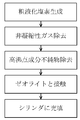
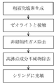
例えば、図1に例示するように、ゼオライトに接触させる前の液化塩素は、食塩水を電解して得られた塩素ガスを液化させ、その後液化物を精留して非凝縮性ガスを分離し、次いで精留物を更に精留して高沸点成分の不純物を分離して得ることができる。更に、図2に例示するように、精製液化塩素は、ゼオライトに接触させた後、且つシリンダに充填する前に、精留して非凝縮性ガスを分離し、その後精留物を更に精留して高沸点成分の不純物を分離して得ることができる。
ゼオライトと液化塩素との接触処理を精留工程の前及び後のどちらで行っても、シリンダ内での酸素ガスの発生抑制の効果を得ることができる。更に、精留前に行う場合は、接触させるゼオライトの粉末が流出する場合が生じても、粉末がシリンダ内に混入することを精留処理で抑制することができる点で好ましい。また、精留後シリンダ充填前に行う場合は、使用したゼオライトを交換することが容易である点から好ましい。
液相部より酸素濃度の変化が把握しやすい気相部については、上記ゼオライトと接触後25日後における上記精製液化塩素を充填したシリンダの気相部に含まれる上記酸素ガス濃度は、例えば1~220vol.ppm(好ましくは1~180、更に好ましくは1~100)とすることができる。
シリンダに充填してから1日後の精製液化塩素中に含まれる酸素ガス濃度Y2(1)と、25日後の精製液化塩素中に含まれる酸素ガス濃度Y2(25)と、の比(X2=Y2(25)/Y2(1))が、1.0~2.1とすることができる。
また、ゼオライトと接触させることによる非接触時と比べての液化塩素中の酸素ガスの増加を抑制した比率を表すX2/X1が、上記X1及びX2の値の範囲内で取り得る範囲である0.2~0.4であり、且つX1及びX2は上記それぞれの範囲内で前記X2/X1の範囲を満たす値とすることができる。
これらの範囲内であれば、シリンダ内での酸素ガスの発生抑制効果を一定以上にすることができ、高純度塩素を長期に渡って純度を保つことができる。
尚、液化塩素中に含まれる酸素ガス濃度は、液化塩素を室温で全量気体にした状態で測定した酸素ガスの濃度とする。
精製液化塩素を充填してから1日後のシリンダの気相部の酸素ガス濃度Y4(1)と、25日後のシリンダの気相部の酸素ガス濃度Y4(25)と、の比(X4=Y4(25)/Y4(1))が、1.0~2.1とすることができる。
また、ゼオライトと接触させることによる非接触時と比べてのシリンダの気相部の酸素ガスの増加を抑制した比率を表すX4/X3が、X4及びX3の値の範囲内で取り得る範囲で例えば0.2~0.7とすることができる。
これらの範囲内であれば、シリンダ内での酸素ガスの発生抑制効果を一定以上にすることができ、高純度塩素を長期に渡って純度を保つことができる。
(1)液化塩素の製造
図1に示すように、食塩水の電気分解により発生した塩素ガスを硫酸で脱水した後、0.7~0.8MPaで圧縮して粗液化塩素を得た。これにより得られた粗液化塩素は、液化率が80~95%であり塩素を99.8%以上含有する。また、粗液化塩素は、不純物として酸素を含有しているため、その後、精留を行うことにより低沸点の非凝縮性ガスである酸素ガス等を除去した。次いで、高沸点成分の不純物である臭素及び金属分等を除去するために、再度精留を行った。これによって含有酸素ガスが0.6vol.ppm(液相部から採取した液化塩素を室温で全量気体にした体積濃度)の液化塩素を得た。
その後、有効直径が0.3nmの3A型合成ゼオライト(モレキュラーシーブ3A、巴工業製)150mLを充填した吸着塔に上記製造方法で製造した液化塩素をSV=13[1/時間]で接触させ、実施例1の精製液化塩素を得た。その後、鋼鉄製シリンダ(容量10L)に容量の6割となる8.5kgを充填した。次いで、室温で保管して、1日、13日及び25日経過後に、酸素ガスの定量分析を行った。分析は、検出器としてPIDを、カラムとして2mの「ユニビーズ1S」及び3mの「モレキュラーシーブ13XS」を、キャリアーガスとしてヘリウムガスを用いたガスクロマトグラフィ(製品名G3900、日立製作所製)により、温度60℃で行った。また、酸素ガスの定量分析は、シリンダ内の液化塩素部(以下、液相部とする)、及び、シリンダ内の気相部に対して行い、濃度を、それぞれ、表1及び表2に示した。
更に、比較例1として、液化塩素原料にゼオライトを接触させずに鋼鉄製シリンダに充填した。また、比較例2として、ゼオライトの代わりに、平均細孔径2.5nmのシリカゲル(「Unibeads 1S」、ジーエルサイエンス社製)を用いた他は、実施例1と同じ製造方法で精製液化塩素を得て、鋼鉄製シリンダに充填した。その後、実施例1と同じ方法で酸素ガスの定量分析を行った。


表1に示すように、シリンダに充填してから1日後の液相部の酸素ガス濃度が、ゼオライトを接触させなかった比較例1では、0.7vol.ppmであったのに対し、ゼオライトと接触させた実施例1及び実施例2はいずれも0.2vol.ppmであり、シリンダ充填時点の酸素ガスの含有量が比較例1と比べて少ないことが分かる。
また、シリカゲルに液化塩素を接触させた比較例2は、液相部の酸素ガス濃度が0.6vol.ppmであり、実施例1及び2の0.2vol.ppmと比較してシリンダ充填時点の酸素ガスの含有量の抑制効果が小さいことが分かる。
表1に示すように、シリンダに充填してから25日後の液相部の酸素ガス濃度が、ゼオライトを接触させなかった比較例1では、2.1vol.ppmであったのに対し、ゼオライトと接触させた実施例1及び実施例2はそれぞれ1.3vol.ppm、及び0.2vol.ppmであり、比較例1よりも酸素ガスの含有量が少ないことが分かる。
一方、ゼオライトと接触させなかった比較例1は、液相部の25日後と1日後の酸素ガス濃度の比X1が2.1/0.7=3.0と増加していることが分かる。つまり、実施例2は、液相部のゼオライト接触による酸素ガスの増加抑制比率X2/X1においては1.0/3.0=0.3と、比較例1と比べて著しく少ないことが分かる。
表2に示すように、シリンダに充填してから1日後の気相部の酸素ガス濃度が、ゼオライトを接触させなかった比較例1では、92vol.ppmであったのに対し、ゼオライトと接触させた実施例1が28vol.ppm、及び実施例2が26vol.ppmであり、シリンダ充填時点の酸素ガスの含有量が液相部と同様に比較例1と比べて少ないことが分かる。
また、シリカゲルに液化塩素を接触させた比較例2は、気相部の酸素ガス濃度が81vol.ppmであり、実施例1の28vol.ppm及び実施例2の26vol.ppmと比較してシリンダ充填時点の酸素ガスの含有量の抑制効果が小さいことが分かる。
表2に示すように、シリンダに充填してから25日後の気相部の酸素ガス濃度が、ゼオライトを接触させなかった比較例1では、330vol.ppmであったのに対し、ゼオライトと接触させた実施例1及び実施例2はそれぞれ169vol.ppm、及び26vol.ppmであり、液相部と同様に比較例1よりも酸素ガスの含有量が少ないことが分かる。
更に、実施例1及び比較例2の充填後1日後と25日後との比較を行うと、液相部における酸素ガス濃度の増加量は、それぞれ1.3-0.2=1.1vol.ppm、及び1.6-0.6=1.0vol.ppmと略同じ値となった。しかし、より微細な変化を観察することができる気相部においては、実施例1の酸素ガス濃度の増加量が169-28=141vol.ppmであるのに対し、比較例2では245-81=161vol.ppmと大きな差があらわれており、実施例1は比較例2よりも酸素ガスの含有量の抑制効果が大きいことが分かる。
一方、ゼオライトと接触させなかった比較例1は、気相部の25日後と1日後の酸素ガス濃度の比X3が330/92=3.6と増加していることが分かる。つまり、実施例2は、気相部のゼオライト接触による酸素ガスの増加抑制比率X4/X3においては1.0/3.6=0.3と、液相部と同様に比較例1と比べて著しく少ないことが分かる。
尚、気相部の酸素ガスが増加したのは、液化塩素に存在する酸素ガスが放出されたためであると考えられる。
また、実施例1及び2は、比較例2に対して細孔の有効直径が小さいにもかかわらず、シリンダ充填1日後の酸素ガス濃度が少ないことが分かる。特に、有効直径が1.0nmの実施例2は、25日間という期間が経過しても酸素ガスの増加を抑制する効果が大きいことが分かる。
これは、図3に例示するように、比較例2が細孔径の分布が広いシリカゲルであるのに対し、実施例1及び2は、細孔径の分布が極めて狭いモレキュラーシーブ(ゼオライト)であるためと考えられる。
Claims (7)
- 液化塩素をゼオライトに接触させ、この接触させて得られた精製液化塩素をシリンダに充填させ、該シリンダ内での酸素ガスの発生を抑制することを特徴とする高純度塩素の製造方法。
- 上記ゼオライトに接触させる前の上記液化塩素は、食塩水を電解して得られた塩素ガスを液化させて得られ、
(1)その後精留されて非凝縮性ガスが分離され、次いで精留されて高沸点成分の不純物が分離され、その後ゼオライトに接触され、次いで上記シリンダに充填される、
若しくは(2)その後上記ゼオライトに接触させて上記精製液化塩素を得て、次いで該精製液化塩素は精留されて非凝縮性ガスが分離され、その後精留されて高沸点成分の不純物が分離され、次いで上記シリンダに充填される請求項1記載の高純度塩素の製造方法。 - 上記ゼオライトと接触後25日後における上記精製液化塩素中に含まれる上記酸素ガス濃度は、0.01~1.5vol.ppmである請求項1又は2記載の高純度塩素の製造方法。
- 上記ゼオライトの細孔の有効直径が0.3nm以上である請求項1乃至3のいずれか一項に記載の高純度塩素の製造方法。
- 上記ゼオライトと接触後25日後における上記精製液化塩素中に含まれる上記酸素ガス濃度は、0.01~1.0vol.ppmである請求項1乃至4のいずれか一項に記載の高純度塩素の製造方法。
- 上記ゼオライトの細孔の有効直径が0.4nm以上である請求項1乃至5のいずれか一項に記載の高純度塩素の製造方法。
- 上記液化塩素を上記ゼオライトに接触させることなく上記シリンダに充填してから25日後と1日後との、該液化塩素中に含まれる酸素ガス濃度の比(X1)が、2.3~6.0であり、
上記精製液化塩素を上記シリンダに充填してから25日後と1日後との、該精製液化塩素中に含まれる酸素ガス濃度の比(X2)が、1.0~2.1であり、
上記X2/上記X1が、0.2~0.4である請求項3乃至6のいずれか一項に記載の高純度塩素の製造方法。
Priority Applications (1)
| Application Number | Priority Date | Filing Date | Title |
|---|---|---|---|
| CN2009801376565A CN102164850A (zh) | 2008-09-24 | 2009-09-16 | 高纯度氯的制造方法 |
Applications Claiming Priority (2)
| Application Number | Priority Date | Filing Date | Title |
|---|---|---|---|
| JP2008244798A JP5544696B2 (ja) | 2008-09-24 | 2008-09-24 | 液化塩素の製造方法 |
| JP2008-244798 | 2008-09-24 |
Publications (1)
| Publication Number | Publication Date |
|---|---|
| WO2010035673A1 true WO2010035673A1 (ja) | 2010-04-01 |
Family
ID=42059674
Family Applications (1)
| Application Number | Title | Priority Date | Filing Date |
|---|---|---|---|
| PCT/JP2009/066189 Ceased WO2010035673A1 (ja) | 2008-09-24 | 2009-09-16 | 高純度塩素の製造方法 |
Country Status (5)
| Country | Link |
|---|---|
| JP (1) | JP5544696B2 (ja) |
| KR (1) | KR101609011B1 (ja) |
| CN (1) | CN102164850A (ja) |
| TW (1) | TWI457285B (ja) |
| WO (1) | WO2010035673A1 (ja) |
Cited By (1)
| Publication number | Priority date | Publication date | Assignee | Title |
|---|---|---|---|---|
| US20230016848A1 (en) * | 2019-12-18 | 2023-01-19 | Covestro Intellectual Property Gmbh & Co. Kg | Method of cleaning an apparatus used in the concentration of a mineral acid |
Families Citing this family (1)
| Publication number | Priority date | Publication date | Assignee | Title |
|---|---|---|---|---|
| US20180354790A1 (en) * | 2015-12-22 | 2018-12-13 | Showa Denko K.K. | Hydrogen chloride mixture, method for producing the same, and filling container |
Citations (5)
| Publication number | Priority date | Publication date | Assignee | Title |
|---|---|---|---|---|
| JPS5265194A (en) * | 1975-11-25 | 1977-05-30 | Tetsuo Takaishi | Method of purifying chlorine or hydrogen chloride for semiconductors |
| JPH08119604A (ja) * | 1994-10-19 | 1996-05-14 | Japan Pionics Co Ltd | ハロゲンガスの精製方法 |
| JP2002316804A (ja) * | 2001-04-19 | 2002-10-31 | Sumitomo Chem Co Ltd | 塩素精製法 |
| WO2005044725A1 (ja) * | 2003-11-05 | 2005-05-19 | Toagosei Co., Ltd. | 高純度液体塩素の製造方法 |
| WO2006035571A1 (ja) * | 2004-09-29 | 2006-04-06 | Showa Denko K.K. | 高純度液化塩素の製造方法 |
-
2008
- 2008-09-24 JP JP2008244798A patent/JP5544696B2/ja not_active Expired - Fee Related
-
2009
- 2009-09-16 CN CN2009801376565A patent/CN102164850A/zh active Pending
- 2009-09-16 KR KR1020117006747A patent/KR101609011B1/ko not_active Expired - Fee Related
- 2009-09-16 WO PCT/JP2009/066189 patent/WO2010035673A1/ja not_active Ceased
- 2009-09-22 TW TW098131924A patent/TWI457285B/zh not_active IP Right Cessation
Patent Citations (5)
| Publication number | Priority date | Publication date | Assignee | Title |
|---|---|---|---|---|
| JPS5265194A (en) * | 1975-11-25 | 1977-05-30 | Tetsuo Takaishi | Method of purifying chlorine or hydrogen chloride for semiconductors |
| JPH08119604A (ja) * | 1994-10-19 | 1996-05-14 | Japan Pionics Co Ltd | ハロゲンガスの精製方法 |
| JP2002316804A (ja) * | 2001-04-19 | 2002-10-31 | Sumitomo Chem Co Ltd | 塩素精製法 |
| WO2005044725A1 (ja) * | 2003-11-05 | 2005-05-19 | Toagosei Co., Ltd. | 高純度液体塩素の製造方法 |
| WO2006035571A1 (ja) * | 2004-09-29 | 2006-04-06 | Showa Denko K.K. | 高純度液化塩素の製造方法 |
Cited By (2)
| Publication number | Priority date | Publication date | Assignee | Title |
|---|---|---|---|---|
| US20230016848A1 (en) * | 2019-12-18 | 2023-01-19 | Covestro Intellectual Property Gmbh & Co. Kg | Method of cleaning an apparatus used in the concentration of a mineral acid |
| US12441614B2 (en) * | 2019-12-18 | 2025-10-14 | Covestro Deutschland Ag | Method of cleaning an apparatus used in the concentration of a mineral acid |
Also Published As
| Publication number | Publication date |
|---|---|
| KR101609011B1 (ko) | 2016-04-04 |
| CN102164850A (zh) | 2011-08-24 |
| JP5544696B2 (ja) | 2014-07-09 |
| TWI457285B (zh) | 2014-10-21 |
| TW201016607A (en) | 2010-05-01 |
| JP2010076953A (ja) | 2010-04-08 |
| KR20110057177A (ko) | 2011-05-31 |
Similar Documents
| Publication | Publication Date | Title |
|---|---|---|
| EP2961688B1 (en) | Adsorbent composition for argon purification | |
| JP7590678B2 (ja) | トリメチルアミンの精製方法 | |
| JP2003286013A (ja) | ガス状三フッ化窒素の精製法 | |
| CN108349755A (zh) | 用于从通过1230xa得到1234yf的方法的无水或含水氢氯酸副产物中去除氟化有机物的方法 | |
| JP5544696B2 (ja) | 液化塩素の製造方法 | |
| US7384618B2 (en) | Purification of nitrogen trifluoride | |
| EP3336057B1 (en) | Method for producing hydrogen chloride | |
| US9174853B2 (en) | Method for producing high purity germane by a continuous or semi-continuous process | |
| CN106044710A (zh) | 一种电子级氯化氢的提纯方法 | |
| CN215101986U (zh) | 一种高纯电子级氯气纯化生产装置 | |
| JP5495642B2 (ja) | 二フッ化カルボニルの精製方法 | |
| KR102612966B1 (ko) | 신규의 옥타플루오로시클로부탄(c4f8) 정제방법 | |
| JP2006143571A (ja) | 塩素ガス、次亜塩素酸ナトリウム水溶液および液体塩素の製造方法 | |
| CN115676786B (zh) | 常温下基于银分子筛吸附的氦氖分离工艺 | |
| JP2007045702A (ja) | クリプトン及び/又はキセノンの製造方法及び装置 | |
| JP2005314132A (ja) | 次亜塩素酸ナトリウム水溶液の製造方法 | |
| JP2004051431A (ja) | 次亜塩素酸ナトリウム水溶液の製造方法 | |
| RU2244705C2 (ru) | Способ очистки гексафторбутадиена | |
| CN112279234B (zh) | 碳酰氟与二氧化碳的共沸组合物 | |
| CN111704108A (zh) | 高纯氯气的连续化生产工艺 | |
| JPH04925B2 (ja) | ||
| JP2003128412A (ja) | 四弗化ケイ素の精製方法 | |
| JP2016166157A (ja) | フッ素化炭化水素化合物充填済みガス充填容器 | |
| KR101520729B1 (ko) | 일산화탄소 흡수액의 제조방법 및 상기 흡수액을 이용하여 전로가스로부터 일산화탄소를 분리 및 회수하는 방법 | |
| CN121669156A (zh) | 一种复合吸附剂及其制备方法 |
Legal Events
| Date | Code | Title | Description |
|---|---|---|---|
| WWE | Wipo information: entry into national phase |
Ref document number: 200980137656.5 Country of ref document: CN |
|
| 121 | Ep: the epo has been informed by wipo that ep was designated in this application |
Ref document number: 09816088 Country of ref document: EP Kind code of ref document: A1 |
|
| ENP | Entry into the national phase |
Ref document number: 20117006747 Country of ref document: KR Kind code of ref document: A |
|
| NENP | Non-entry into the national phase |
Ref country code: DE |
|
| 122 | Ep: pct application non-entry in european phase |
Ref document number: 09816088 Country of ref document: EP Kind code of ref document: A1 |