WO2010035527A1 - ゲーム装置、ゲーム装置の制御方法、プログラム及び情報記憶媒体 - Google Patents
ゲーム装置、ゲーム装置の制御方法、プログラム及び情報記憶媒体 Download PDFInfo
- Publication number
- WO2010035527A1 WO2010035527A1 PCT/JP2009/055198 JP2009055198W WO2010035527A1 WO 2010035527 A1 WO2010035527 A1 WO 2010035527A1 JP 2009055198 W JP2009055198 W JP 2009055198W WO 2010035527 A1 WO2010035527 A1 WO 2010035527A1
- Authority
- WO
- WIPO (PCT)
- Prior art keywords
- game
- image
- player
- attention area
- display control
- Prior art date
Links
Images


Classifications
-
- A—HUMAN NECESSITIES
- A63—SPORTS; GAMES; AMUSEMENTS
- A63F—CARD, BOARD, OR ROULETTE GAMES; INDOOR GAMES USING SMALL MOVING PLAYING BODIES; VIDEO GAMES; GAMES NOT OTHERWISE PROVIDED FOR
- A63F13/00—Video games, i.e. games using an electronically generated display having two or more dimensions
- A63F13/50—Controlling the output signals based on the game progress
- A63F13/53—Controlling the output signals based on the game progress involving additional visual information provided to the game scene, e.g. by overlay to simulate a head-up display [HUD] or displaying a laser sight in a shooting game
- A63F13/537—Controlling the output signals based on the game progress involving additional visual information provided to the game scene, e.g. by overlay to simulate a head-up display [HUD] or displaying a laser sight in a shooting game using indicators, e.g. showing the condition of a game character on screen
- A63F13/5372—Controlling the output signals based on the game progress involving additional visual information provided to the game scene, e.g. by overlay to simulate a head-up display [HUD] or displaying a laser sight in a shooting game using indicators, e.g. showing the condition of a game character on screen for tagging characters, objects or locations in the game scene, e.g. displaying a circle under the character controlled by the player
-
- A—HUMAN NECESSITIES
- A63—SPORTS; GAMES; AMUSEMENTS
- A63F—CARD, BOARD, OR ROULETTE GAMES; INDOOR GAMES USING SMALL MOVING PLAYING BODIES; VIDEO GAMES; GAMES NOT OTHERWISE PROVIDED FOR
- A63F13/00—Video games, i.e. games using an electronically generated display having two or more dimensions
- A63F13/50—Controlling the output signals based on the game progress
- A63F13/53—Controlling the output signals based on the game progress involving additional visual information provided to the game scene, e.g. by overlay to simulate a head-up display [HUD] or displaying a laser sight in a shooting game
-
- A—HUMAN NECESSITIES
- A63—SPORTS; GAMES; AMUSEMENTS
- A63F—CARD, BOARD, OR ROULETTE GAMES; INDOOR GAMES USING SMALL MOVING PLAYING BODIES; VIDEO GAMES; GAMES NOT OTHERWISE PROVIDED FOR
- A63F13/00—Video games, i.e. games using an electronically generated display having two or more dimensions
- A63F13/50—Controlling the output signals based on the game progress
- A63F13/52—Controlling the output signals based on the game progress involving aspects of the displayed game scene
-
- A—HUMAN NECESSITIES
- A63—SPORTS; GAMES; AMUSEMENTS
- A63F—CARD, BOARD, OR ROULETTE GAMES; INDOOR GAMES USING SMALL MOVING PLAYING BODIES; VIDEO GAMES; GAMES NOT OTHERWISE PROVIDED FOR
- A63F13/00—Video games, i.e. games using an electronically generated display having two or more dimensions
- A63F13/55—Controlling game characters or game objects based on the game progress
- A63F13/56—Computing the motion of game characters with respect to other game characters, game objects or elements of the game scene, e.g. for simulating the behaviour of a group of virtual soldiers or for path finding
-
- A—HUMAN NECESSITIES
- A63—SPORTS; GAMES; AMUSEMENTS
- A63F—CARD, BOARD, OR ROULETTE GAMES; INDOOR GAMES USING SMALL MOVING PLAYING BODIES; VIDEO GAMES; GAMES NOT OTHERWISE PROVIDED FOR
- A63F13/00—Video games, i.e. games using an electronically generated display having two or more dimensions
- A63F13/80—Special adaptations for executing a specific game genre or game mode
- A63F13/812—Ball games, e.g. soccer or baseball
-
- A—HUMAN NECESSITIES
- A63—SPORTS; GAMES; AMUSEMENTS
- A63F—CARD, BOARD, OR ROULETTE GAMES; INDOOR GAMES USING SMALL MOVING PLAYING BODIES; VIDEO GAMES; GAMES NOT OTHERWISE PROVIDED FOR
- A63F13/00—Video games, i.e. games using an electronically generated display having two or more dimensions
- A63F13/50—Controlling the output signals based on the game progress
- A63F13/53—Controlling the output signals based on the game progress involving additional visual information provided to the game scene, e.g. by overlay to simulate a head-up display [HUD] or displaying a laser sight in a shooting game
- A63F13/537—Controlling the output signals based on the game progress involving additional visual information provided to the game scene, e.g. by overlay to simulate a head-up display [HUD] or displaying a laser sight in a shooting game using indicators, e.g. showing the condition of a game character on screen
- A63F13/5378—Controlling the output signals based on the game progress involving additional visual information provided to the game scene, e.g. by overlay to simulate a head-up display [HUD] or displaying a laser sight in a shooting game using indicators, e.g. showing the condition of a game character on screen for displaying an additional top view, e.g. radar screens or maps
-
- A—HUMAN NECESSITIES
- A63—SPORTS; GAMES; AMUSEMENTS
- A63F—CARD, BOARD, OR ROULETTE GAMES; INDOOR GAMES USING SMALL MOVING PLAYING BODIES; VIDEO GAMES; GAMES NOT OTHERWISE PROVIDED FOR
- A63F2300/00—Features of games using an electronically generated display having two or more dimensions, e.g. on a television screen, showing representations related to the game
- A63F2300/30—Features of games using an electronically generated display having two or more dimensions, e.g. on a television screen, showing representations related to the game characterized by output arrangements for receiving control signals generated by the game device
- A63F2300/303—Features of games using an electronically generated display having two or more dimensions, e.g. on a television screen, showing representations related to the game characterized by output arrangements for receiving control signals generated by the game device for displaying additional data, e.g. simulating a Head Up Display
-
- A—HUMAN NECESSITIES
- A63—SPORTS; GAMES; AMUSEMENTS
- A63F—CARD, BOARD, OR ROULETTE GAMES; INDOOR GAMES USING SMALL MOVING PLAYING BODIES; VIDEO GAMES; GAMES NOT OTHERWISE PROVIDED FOR
- A63F2300/00—Features of games using an electronically generated display having two or more dimensions, e.g. on a television screen, showing representations related to the game
- A63F2300/60—Methods for processing data by generating or executing the game program
- A63F2300/64—Methods for processing data by generating or executing the game program for computing dynamical parameters of game objects, e.g. motion determination or computation of frictional forces for a virtual car
-
- A—HUMAN NECESSITIES
- A63—SPORTS; GAMES; AMUSEMENTS
- A63F—CARD, BOARD, OR ROULETTE GAMES; INDOOR GAMES USING SMALL MOVING PLAYING BODIES; VIDEO GAMES; GAMES NOT OTHERWISE PROVIDED FOR
- A63F2300/00—Features of games using an electronically generated display having two or more dimensions, e.g. on a television screen, showing representations related to the game
- A63F2300/60—Methods for processing data by generating or executing the game program
- A63F2300/66—Methods for processing data by generating or executing the game program for rendering three dimensional images
- A63F2300/6653—Methods for processing data by generating or executing the game program for rendering three dimensional images for altering the visibility of an object, e.g. preventing the occlusion of an object, partially hiding an object
-
- A—HUMAN NECESSITIES
- A63—SPORTS; GAMES; AMUSEMENTS
- A63F—CARD, BOARD, OR ROULETTE GAMES; INDOOR GAMES USING SMALL MOVING PLAYING BODIES; VIDEO GAMES; GAMES NOT OTHERWISE PROVIDED FOR
- A63F2300/00—Features of games using an electronically generated display having two or more dimensions, e.g. on a television screen, showing representations related to the game
- A63F2300/80—Features of games using an electronically generated display having two or more dimensions, e.g. on a television screen, showing representations related to the game specially adapted for executing a specific type of game
- A63F2300/8011—Ball
Definitions
- the present invention relates to a game device that executes a game in which a plurality of game characters appear, a method for controlling the game device, a program, and an information storage medium.
- a game device that executes a game in which a plurality of game characters appear is known.
- a soccer game in which a plurality of player characters appear is known (the following Patent Document 1).
- the present invention has been made in view of the above problems, and allows a player to grasp the positional relationship of each game character and the direction of each game character even when the game characters are densely located in a certain area.
- One of the purposes is to provide a game device, a game device control method, a program, and an information storage medium.
- a game apparatus includes a game execution unit that executes a game in which a plurality of game characters appear, and a display control unit that displays a game screen including an image of the game character.
- the display control means restricts the display of the image of the game character located in the attention area when a game character of a reference number or more is located in the given attention area, An alternative image having a smaller area is displayed on the game screen.
- the method for controlling a game device includes a step of executing a game in which a plurality of game characters appear, and a display control step for displaying a game screen including an image of the game character,
- the display control step restricts the display of the image of the game character positioned in the attention area when there are more than the reference number of game characters in the given attention area, and the area is larger than the image.
- the program according to the present invention is a stationary game machine (home game machine) as a game execution means for executing a game in which a plurality of game characters appear, and a display control means for displaying a game screen including an image of the game character.
- a stationary game machine home game machine
- the display control means for displaying a game screen including an image of the game character.
- the display control means has a game character of a reference number or more within a given region of interest.
- the information storage medium according to the present invention is a computer-readable information storage medium recording the above program.
- the present invention relates to a game apparatus including a game execution unit that executes a game in which a plurality of game characters appear, and a display control unit that displays a game screen including an image of the game character.
- a game execution unit that executes a game in which a plurality of game characters appear
- a display control unit that displays a game screen including an image of the game character.
- the display of the image of the game character located in the attention area is restricted, and the area is larger than the image.
- a small substitute image is displayed on the game screen.
- an alternative image having a smaller area than the image is displayed on the game screen. Therefore, according to the present invention, the player can grasp the positional relationship of each game character and the direction of each game character even when the game characters are densely located in a certain area.
- the game is a sport game performed using a moving object
- the game character is a player character
- the game device satisfies the conditions relating to the moving mode of the moving object.
- the game device In association therewith further includes a condition storage means for storing the part of the player character, wherein the display control means is adapted to satisfy a condition that the moving mode of the moving object is satisfied among the parts of the player character located in the attention area. You may make it display the said alternative image in the position in the game screen according to the position of the related site
- the plurality of game characters include a game character associated with an operation target group of a player, and a game character associated with an opponent group opposed to the operation target group
- the display control means may restrict display of an image of a game character associated with the opponent group among game characters located in the attention area and display the substitute image.
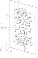
- FIG. 1 shows a hardware configuration of a portable game machine 10 (game device) according to an embodiment of the present invention.
- the portable game machine 10 includes a bus 12, a microprocessor 14, a main memory 16, an image processing unit 18, a liquid crystal monitor 20, an input / output processing unit 22, an audio processing unit 24, a speaker 26, and a wireless communication interface 28.
- This is a known computer game system that includes an optical disc playback unit 30, an optical disc 32, and an operation input unit. These are housed in a casing together with a battery, and the portable game machine 10 is driven by the battery. According to the portable game machine 10, the player can play the game regardless of the place.
- the bus 12 is used for exchanging addresses and data among the units of the portable game machine 10.
- the microprocessor 14, the main memory 16, the image processing unit 18, and the input / output processing unit 22 are connected by the bus 12 so that mutual data communication is possible.
- the microprocessor 14 controls each part of the portable game machine 10 based on an operating system stored in a ROM (not shown) and a game program stored in the optical disc 32.
- the main memory 16 includes, for example, a RAM, and a game program and game data read from the optical disc 32 are written as necessary.
- the main memory 16 is also used for work of the microprocessor 14.
- the image processing unit 18 includes a VRAM, and draws an image on the VRAM based on the image data sent from the microprocessor 14. Then, the image processing unit 18 displays the image drawn on the VRAM as a game screen on the liquid crystal monitor 20 at a predetermined timing.
- the liquid crystal monitor 20 is a known liquid crystal monitor.
- the input / output processing unit 22 is an interface for the microprocessor 14 to exchange data with the audio processing unit 24, the wireless communication interface 28, the optical disc playback unit 30, and the operation input unit 34.
- An audio processing unit 24, a wireless communication interface 28, an optical disc playback unit 30, and an operation input unit 34 are connected to the input / output processing unit 22.
- the audio processing unit 24 includes a sound buffer, and outputs various audio data such as game music, game sound effects, and messages read from the optical disc 32 and stored in the sound buffer from the speaker 26.
- the wireless communication interface 28 is an interface for wirelessly connecting the portable game machine 10 to another portable game machine 10 or connecting the portable game machine 10 to a communication network such as the Internet.
- the wireless communication interface 28 is an interface for wireless communication conforming to, for example, the IEEE 802.11 standard.
- the optical disc playback unit 30 reads out the game program and game data stored in the optical disc 32 in accordance with instructions from the microprocessor 14.
- the optical disc 32 is used to supply the game program and game data to the portable game machine 10, but any other information storage medium such as a game card may be used. It is also possible to supply game programs and game data to the portable game machine 10 from a remote location via a communication network such as the Internet. Furthermore, it is also possible to supply a game program and game data to the portable game machine 10 from a stationary game machine, a personal computer, etc. using various data communications such as infrared communication.
- the operation input unit 34 is an input means for a player to input a game operation.
- the operation input unit 34 includes, for example, a direction instruction key and one or a plurality of buttons.
- the input / output processing unit 22 scans the state of the operation input unit 34 at regular intervals (for example, every 1/60 seconds), and passes an operation signal representing the scan result to the microprocessor 14 via the bus 12.
- the microprocessor 14 determines the game operation of the player based on the operation signal.
- a player object game character associated with a team to be operated by a player (hereinafter referred to as an operation target team) is operated to operate the operation target team (operation target).
- a soccer game is provided that aims to generate more scoring events than the opponent team (opposition group) that is hostile to the group. This soccer game is realized by executing a soccer game program read from the optical disc 32.
- FIG. 2 is a diagram showing an example of a game space constructed in the main memory 16 in order to provide the soccer game.
- the game space may be a two-dimensional space.
- an XW axis, a YW axis, and a ZW axis are set in the game space.
- the position in the game space is specified by the XW coordinate value, YW coordinate value, and ZW coordinate value (world coordinate value) of the position.
- a field object 36 indicating a soccer field is arranged in the game space.
- the field object 36 is arranged in parallel to the XW-ZW plane.
- the field object 36 includes a center mark 38 at the center thereof.
- the goal object 46 is associated with the opponent team.
- the goal object 48 is associated with the operation target team. When the ball object 44 moves to the goal object 46, a score event of the operation target team occurs, and when the ball object 44 moves to the goal object 48, a score event of the opponent team occurs.
- Each player object 40, 42 has a virtual skeleton defined by, for example, a skeleton model.
- the positions of the player objects 40 and 42 in the game space are specified by the world coordinate values of the pelvis in the skeleton model.
- each player object 40 depending on the rotation angle of each bone (rotation angle of the child bone with respect to the parent bone), the relative position of each joint viewed from the pelvis, etc. determined based on the rotation angle of each bone. 42 postures are identified.
- the player object 40 belonging to the operation target team is associated with the operation target team
- the player object 42 belonging to the opponent team is associated with the opponent team.
- the player object 40 associated with the operation target team is referred to as an operation target object 40
- the player object 42 associated with the opponent team is referred to as an opponent object 42.
- the operation target object 40 and the opponent object 42 are not distinguished from each other, they are described as “player objects”.
- any one of the operation target objects 40 is an operation target of the player.
- the operation target object 40 that is the operation target of the player is referred to as a player object.
- the player object performs various operations based on operation signals input from the operation input unit 34. For example, when a predetermined button (not shown) is pressed while the ball object 44 is held, the player object performs a pass action and moves toward a position around one of the other operation target objects 40. The ball object 44 is kicked out.
- the angle at which the player object kicks up the ball object 44 is set to increase in accordance with the length of time that the predetermined button is pressed.
- the ball object 44 moves in the air when the predetermined button is pressed for a long time, and moves on the field object 36 when the predetermined button is pressed for a short time. It becomes.
- player objects other than the player object also perform various operations according to a predetermined algorithm.
- the player object is switched by the player's operation. It is also switched by the movement of the ball object 44. For example, when the player object performs a pass action and kicks the ball object 44, the player object is switched to another operation target object 40. In the present embodiment, when the player object performs a pass action, the player object is selected from the other operation target objects 40 selected based on the movement destination position of the ball object 44 predicted from the movement direction of the ball object 44 or the like. Switch.
- the ball object 44 when the ball object 44 is not held by any player object, the ball object 44 is held by the player object only when the ball object 44 and any part of the player object collide. Or the movement direction of the ball object 44 changes. For example, when the ball object 44 collides with the foot of the player object performing the shooting action, the ball object 44 moves toward the goal object 46.
- a virtual camera 49 is arranged above the field object 36.
- the virtual camera 49 is set above the center mark 38.
- the microprocessor 14 causes the liquid crystal monitor 20 to display a game screen representing a state in which the game space is viewed from the virtual camera 49.
- the visual line direction of the virtual camera 49 is set so that the player can easily grasp the position of each player object placed on the field object 36.
- the visual line direction of the virtual camera 49 is set to the negative direction of the YW axis (that is, the direction toward the center mark 38).
- the line-of-sight direction of the virtual camera 49 may not be the negative direction of the YW axis.
- the line-of-sight direction of the virtual camera 49 may be “a direction in which the angle formed with the negative direction of the YW axis is a predetermined angle (for example, 10 degrees) or less”.
- the line-of-sight direction of the virtual camera 49 may change during a soccer game.
- the microprocessor 14 may appropriately change the line-of-sight direction of the virtual camera 49 within a range in which the angle formed with the negative direction of the YW axis does not exceed the predetermined angle.
- the height of the virtual camera 49 from the field object 36 (that is, the YW coordinate value of the virtual camera 49) is set so that the entire field object 36 is included in the visual field range of the virtual camera 49. ing.
- a game screen including the entire field object 36 is displayed on the liquid crystal monitor 20 as shown in FIG.
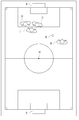
- FIG. 3 shows an example of a game screen displayed on the liquid crystal monitor 20.
- the game screen includes an image of each player object, an image of the ball object 44, and the like.
- the entire field object 36 does not necessarily have to be included in the visual field range of the virtual camera 49.
- the microprocessor 14 may move the virtual camera 49 in parallel with the XW-ZW plane according to the movement of the ball object 44 so that at least the ball object 44 is included in the visual field range of the virtual camera 49.
- a position guide image 50 having a smaller area than the image of each player object is displayed on the game screen instead of the image of each player object.
- an arrow-shaped image that indicates the front direction of each player object is displayed on the game screen as the position guide image 50.
- FIG. 4 shows an example of the game screen when the position guide image 50 is displayed.
- the player can grasp the positional relationship of each player object and the direction of each player object even when a plurality of player objects are densely packed. It is like that.
- the player object image is indicated by a broken line, but the player object image is not actually displayed.
- the position guide image 50 has an arrow shape, but the position guide image 50 may have any shape.
- the position guide image 50 may have a circular shape or a rectangular shape, or a triangular shape that indicates the front direction of each player object.
- FIG. 5 is a functional block diagram mainly showing functions related to the present invention among the functions realized in the portable game machine 10.
- the portable game machine 10 includes a game data storage unit 52, a game data update unit 54 (game execution means), and a game screen display control unit 56 (display control means).
- the game screen display control unit 56 includes a congestion determination unit 58, a game screen generation unit 60, and a game screen output unit 62. These functions are realized by the program read from the optical disc 32 being executed by the microprocessor 14.
- the game data storage unit 52 is realized mainly by the main memory 16 and the optical disc 32.
- the game data storage unit 52 stores various game data.
- the game data storage unit 52 stores data stored in advance on the optical disc 32 (for example, “motion data of each player object (rotation angle of each bone at each timing”, “texture image to be attached to each object”), and “ Further, the game situation data indicating the current situation of the game space (for example, “position, movement direction, movement speed, and posture of each player object (ID of motion data being reproduced)” is stored.
- the playback position of the motion data “position, moving direction and moving speed of the ball object 44”, “data for specifying the player object holding the ball object 44”, “specifying the player object” Data for “virtual camera 49”, etc.) That.
- the game data update unit 54 is realized mainly by the microprocessor 14.
- the game data update unit 54 updates the game situation data stored in the game data storage unit 52 based on the operation signal input from the operation input unit 34 and a predetermined algorithm.
- the game data update unit 54 executes the soccer game. For example, when the predetermined button is pressed while the player object is holding the ball object 44, the game data update unit 54 determines the initial movement direction and the initial movement speed of the ball object 44. In the present embodiment, the initial movement direction is determined so that the angle between the initial movement direction and the XW-ZW plane increases as the time for which the predetermined button is pressed is longer. After that, the game data update unit 54 performs a predetermined physics calculation and updates the subsequent movement direction, movement speed, and position of the ball object 44.
- the game screen display control unit 56 is realized mainly by the microprocessor 14 and the image processing unit 18.
- the game screen display control unit 56 causes the liquid crystal monitor 20 to display a game screen representing a state where the game space is viewed from the virtual camera 49.
- the game screen display control part 56 when the player object more than the reference number N (N is an integer greater than or equal to 2) is located in a given attention area, the player object located in the attention area The display of at least one of the images is restricted, and the position guide image 50 is displayed on the game screen.
- the game screen display control unit 56 when the player object of the reference number N or more is located in the attention area, the position guidance image instead of the image of the player object located in the attention area. 50 is displayed on the game screen.
- the density determination unit 58, the game screen generation unit 60, and the game screen output unit 62 included in the game screen display control unit 56 will be described.
- the congestion determination unit 58 is realized mainly by the microprocessor 14.
- the congestion determination unit 58 determines whether or not a predetermined congestion condition is satisfied.
- the crowding condition is a condition that is satisfied when player objects of the reference number N or more are located in the attention area.
- the congestion determination unit 58 performs the pass action when the predetermined button is pressed when the player object holds the ball object 44 (the player object holding the ball object 44 performs a pass action). In this case, based on the initial moving direction and initial moving speed of the ball object 44, a reference position serving as a reference for determining the attention area is determined. Then, the congestion determination unit 58 determines whether or not the congestion condition is satisfied with the region including the reference position as a region of interest.
- the congestion determination unit 58 determines the reference position based on the drop point of the ball object 44 predicted from the initial movement speed and the initial movement direction of the ball object 44. For example, the congestion determination unit 58 determines the drop point itself of the ball object 44 as the reference position. Further, for example, the congestion determination unit 58 selects an operation target object 40 (hereinafter referred to as a notable player object) that becomes a player object next to the player object that performed the pass action based on the drop point of the ball object 44. Then, the reference position is determined based on the position of the noted player object.
- an operation target object 40 hereinafter referred to as a notable player object
- the congestion determination unit 58 may determine the position of the opponent object 42 having the smallest distance from the notable player object as the reference position, or the notable player object The position itself may be determined as the reference position. When the position of the focused player object itself becomes the reference position, selecting the focused player object itself corresponds to determining the reference position.
- the attention player object is, for example, the operation target object 40 having the shortest distance from the drop point of the ball object 44.
- the congestion determination unit 58 determines whether the congestion condition is satisfied. For example, when the position of the focused player object is not the reference position, the congestion determination unit 58 determines whether or not the congestion condition is satisfied by determining whether or not N or more player objects are positioned in the focused area. Determine. In this case, the density determination unit 58 determines that the density condition is satisfied if N or more player objects are located in the attention area. Further, for example, when the position of the target player object is the reference position, it is obvious that the target player object is located in the target area. It is determined whether or not “N ⁇ 1” bodies or more are located in the attention area.
- FIG. 6 is a diagram illustrating an example of a positional relationship between the reference position and each player object.
- Point O represents the reference position
- point P represents the player object
- point Q represents the position of the operation target object 40 other than the player object
- point R represents the position of the opponent object 42.
- the position of the noted player object is the reference position O
- the position P of the player object is the reference position O.
- the position of the pelvis in the skeleton model of each player object is the position of each player object.
- a region surrounded by a broken line represents the attention region 51.
- an area where the distance from the point O is equal to or less than the reference distance L is set as the attention area 51.
- the point O, the point P, the point Q, and the point R are the reference position, the player object, the operation target object 40 other than the player object, and the “position in the game space (world coordinate space) of the opponent object 42, respectively. Or “position on the game screen (screen coordinate plane)”.
- the attention area 51 is represented as a spherical or circular area centered on the reference position O, but the shape of the attention area 51 is any shape (for example, the reference position O is the center of gravity). It may be a cubic shape, a square shape, or the like.
- the game screen generation unit 60 is realized mainly by the microprocessor 14 and the image processing unit 18.
- the game screen generation unit 60 generates an image representing a state in which the game space is viewed from the virtual camera 49 based on the game situation data stored in the game data storage unit 52.
- the game screen generation unit 60 generates an image by rendering processing after performing coordinate conversion from the world coordinate system to the screen coordinate system by geometry processing. Then, the game screen generation unit 60 draws the image thus generated on the VRAM.
- the game screen generation unit 60 displays an image on the VRAM so that the position guide image 50 is displayed on the game screen instead of the image of the player object located in the attention area 51 when the congestion condition is satisfied. Draw.
- the game screen generation unit 60 sets the player object positioned in the attention area 51 to be transparent, and generates an image representing a state in which the game space is viewed from the virtual camera 49. Then, the game screen generating unit 60 draws this image on the VRAM, and then draws the position guide image 50 by overwriting at the position indicated by the screen coordinate value of the player object located in the attention area 51.
- the position indicated by the screen coordinate value is referred to as a screen position.
- the game screen generation unit 60 replaces the player object located in the attention area 51 with a position guide object (for example, a width in the direction parallel to the XW-ZW plane) smaller than the shoulder width of the player object.
- a position guide object for example, a width in the direction parallel to the XW-ZW plane
- a ball object having a diameter smaller than the shoulder width of the player object is arranged, and an image representing a state in which the game space is viewed from the virtual camera 49 is generated and drawn on the VRAM.
- the position guide image 50 having a smaller area than the image is displayed on the game screen.
- the game screen output unit 62 is realized mainly by the image processing unit 18.
- the game screen output unit 62 displays an image drawn on the VRAM on the liquid crystal monitor 20 as a game screen.
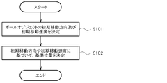
- Processing executed in portable game machine 7 and 8 are flowcharts showing processing executed in the portable game machine 10. The processing shown in FIGS. 7 and 8 is executed by the microprocessor 14 operating in accordance with a program stored in the optical disc 32.
- the microprocessor 14 determines the initial moving direction and the initial moving speed of the ball object 44 (S101). Here, the microprocessor 14 determines the initial movement direction so that the angle between the initial movement direction and the XW-ZW plane becomes larger as the predetermined button is pressed longer.
- the microprocessor 14 determines the reference position O based on the initial movement direction and the initial movement speed (S102). For example, the microprocessor 14 performs a predetermined physical calculation and calculates the drop point of the ball object 44 based on the position of the ball object 44, the initial movement direction, and the initial movement speed. Based on this, the microprocessor 14 determines the reference position O based on this drop point. For example, the microprocessor 14 determines the drop point itself as the reference position O. Further, for example, the microprocessor 14 determines the position P of the noted player object (that is, the operation target object 40 to be the next player object) having the smallest distance from the falling point as the reference position O. Further, for example, the microprocessor 14 determines the position R of the opponent object 42 having the smallest distance from the noted player object as the reference position O.
- the microprocessor 14 updates the game situation data (S201). For example, the microprocessor 14 updates the moving direction and moving speed of the ball object 44 based on the result of the physical calculation. Further, the microprocessor 14 updates the position of the ball object 44 based on the moving direction and moving speed of the ball object 44.
- the microprocessor 14 determines whether or not the congestion condition is satisfied by executing the step of S202.
- the microprocessor 14 determines whether or not the player object is positioned in the target area 51 by N bodies or more. For example, the microprocessor 14 determines whether or not there are N or more player objects whose distance from the reference position O is equal to or less than the reference distance L, so that N or more player objects are positioned in the attention area 51. It is determined whether or not. When N or more player objects are located in the attention area 51, the microprocessor 14 determines that the congestion condition is satisfied.
- the microprocessor 14 performs a player object other than the noticeable player object. It is determined whether “N ⁇ 1” bodies or more are located in the attention area 51. For example, the microprocessor 14 determines whether or not there are “N ⁇ 1” or more player objects whose distance from the target player object (that is, the reference position O) is equal to or less than the reference distance L. It is determined whether or not player objects other than the object are located in the attention area 51 by “N ⁇ 1” bodies or more. If there are “N ⁇ 1” or more player objects in the attention area 51 other than the attention player object, the microprocessor 14 determines that the congestion condition is satisfied.
- the microprocessor 14 (display control means) generates an image representing a state in which the game space is viewed from the virtual camera 49 (S203). Specifically, the microprocessor 14 performs coordinate conversion from the world coordinate system to the screen coordinate system by geometry processing, and then generates an image by rendering processing. When the image is generated in this way, the microprocessor 14 (display control means) draws this image on the VRAM (S204). As a result, the image shown in FIG. 3 is formed on the VRAM.
- the microprocessor 14 sets the player object located in the attention area 51 to be transparent, and generates an image representing the game space viewed from the virtual camera 49 (S205). Then, drawing is performed on the VRAM (S206). For example, in step S205, the microprocessor 14 sets these player objects to be transparent by setting the ⁇ value of the player objects located within the attention area 51 to “0”. On this basis, the microprocessor 14 generates an image representing the game space viewed from the virtual camera 49 in the same manner as in step S203.
- step S207 the microprocessor 14 (display control means) overwrites and draws the position guide image 50 on the screen position of the player object located in the attention area 51 (S207).
- the microprocessor 14 color-codes the position guidance image 50 of the operation target object 40 located in the attention area 51 and the position guidance image 50 of the opponent object 42 located in the attention area 51. To do.
- the image shown in FIG. 4 is formed on the VRAM.
- the microprocessor 14 may further color-code the position guide image 50 of the target player object and the position guide image 50 of the operation target object 40 located in the target area 51.
- the image processing unit 18 causes the liquid crystal monitor 20 to display an image drawn on the VRAM as a game screen (S208).
- a reduced image of the image of the player object located in the attention area 51 may be displayed on the game screen.
- the microprocessor 14 generates an image obtained by viewing the player object located in the attention area 51 from the virtual camera 49 (hereinafter referred to as a character image), and then, in step S207, the character image is displayed.
- the reduced image may be overwritten and drawn at the screen position of the player object located in the attention area 51. This makes it easier for the player to grasp the positional relationship of each player object located in the attention area 51 and the direction of each player object without impairing the reality regarding display of the game screen.
- the microprocessor 14 may change the size of the attention area 51 in accordance with the reference position O.
- the reference number N is set to a constant value, depending on the value of the reference number N, the reality regarding the display of the game screen may be excessively impaired.
- the microprocessor 14 may change the value of the reference number N in accordance with the reference position O.
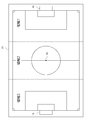
- the field object 36 is partitioned into a plurality of regions from region 1 to region 3.
- a position condition table is prepared which stores a parameter value for determining the size of the attention area 51 and a reference number N value.
- the value of the reference distance L is stored in the position condition table as the parameter value.
- FIG. 10 is a diagram showing an example of the position condition table.
- the microprocessor 14 specifies a position condition that the reference position O satisfies, and uses the value of the reference distance L and the value of the reference number N associated with the position condition to perform the processing shown in FIG. Should be executed.
- the size of the attention area 51 and the reference number N change according to the reference position O.
- the reference number N changes according to the size of the attention area 51.
- the size of the attention area 51 when the ball object 44 is moving in the vicinity of the goal objects 46 and 48, and the ball object 44 is moved around the center mark 38 is larger than the size of the attention area 51 in the case of the Therefore, the player can position the player object over a wider range when the ball object 44 is moving near the goal objects 46 and 48 than when the ball object 44 is moving near the center mark 38. It becomes easy to grasp.
- the display of the image of the player object located in the attention area 51 is not limited. Even if the height changes, the reality regarding the display of the game screen is not impaired.
- the display of the image of all the player objects located in the attention area 51 was restrict
- the player particularly grasps the positional relationship between the player object and the opponent object 42 in order to cause the player object to reliably hold or shoot the moving ball object 44.
- the display of the image of the opponent object 42 among the player objects located in the attention area 51 may be limited.
- the microprocessor 14 sets the opponent object 42 among the player objects located in the attention area 51 to be transparent in the step of S205, while the screen of the opponent object 42 is set in the step of S207.
- the position guide image 50 may be overwritten and drawn at the position.
- the player can grasp the positional relationship between the player object and the opponent object 42 positioned in the attention area 51 and the direction of each opponent object 42. As a result, the player can reliably hold or shoot the moving ball object 44 by the player object. Further, since only the display of the image of the opponent object 42 located in the attention area 51 is restricted, the display of the images of all the player objects located in the attention area 51 is restricted. Thus, the reality regarding the display of the game screen is not impaired.
- the mode for limiting the display of the player object located in the attention area 51 is not limited to this mode.
- the image of the player object located in the attention area 51 may be displayed in a translucent manner.
- the microprocessor 14 sets the ⁇ value of the player object located in the attention area 51 to a value other than “0” and “1” (for example, 0.5). That's fine. This makes it easier for the player to grasp the positional relationship of each player object located in the attention area 51 and the direction of each player object without impairing the reality regarding display of the game screen.
- the microprocessor 14 displays the position guide image 50 at the screen position of the “pelvis” of the player object located in the attention area 51, to be precise.
- the ball object 44 is held by the player object when the ball object 44 collides with any part of the player object.
- the moving direction of the ball object 44 changes. Therefore, for example, in order for the player object to securely hold or shoot the ball object 44 moving on the field object 36, the player's foot of each player object located in the attention area 51 is used. It is necessary to grasp the position of the.
- the microprocessor 14 may change the position of the position guide image 50 in the game screen according to the movement mode of the ball object 44.
- a movement mode condition table in which the movement mode conditions related to the movement mode of the ball object 44 and the part of the player object are associated with each other is stored in advance in the main memory 16 (condition storage means).
- FIG. 11 shows an example of the contents of the movement mode condition table.
- the movement mode condition table stores a condition relating to the angle between the initial movement direction of the ball object 44 and the XW-ZW plane as the movement mode condition.
- a predetermined angle ⁇ for example, 5 degrees
- the movement mode condition associated with the “foot” is satisfied.
- the movement mode condition associated with “pelvis (head)” is satisfied.
- the microprocessor 14 (display control means) identifies a movement mode condition that satisfies the initial movement direction of the ball object 44, and in step S207, the screen position of the part associated with the movement mode condition.
- the position guide image 50 may be overwritten.
- the microprocessor 14 determines the screen position of the part based on the relative position of each joint viewed from the pelvis and the position of the pelvis, which is determined based on the rotation angle of each bone of the player object. After calculating the world coordinate value, the world coordinate value may be calculated by screen conversion.
- the position of the position guide image 50 in the game screen changes according to the movement mode of the ball object 44.
- the player can reliably hold or shoot the moving ball object 44 by the player object.
- the movement mode condition is a condition related to the angle between the initial movement direction of the ball object 44 and the XW-ZW plane, but the movement mode condition may be other conditions.
- FIG. 13 is an example of the game screen in this mode.
- the microprocessor 14 displays a first gauge image 72 that expands as the YW coordinate value of the head of the player object increases, and a second gauge image 74 that expands as the YW coordinate value of the ball object 44 increases. Display on the screen.
- the microprocessor 14 may arrange the first gauge image 72 and the second gauge image 74 on the reference line 70 and perform overwriting on the VRAM.
- the microprocessor 14 determines the height value H1 of the first gauge image 72 so as to increase as the YW coordinate value of the head of the player object increases, and increases as the YW coordinate value of the ball object 44 increases.
- the height value H2 of the second gauge image 74 is determined in advance.
- the microprocessor 14 calculates the value of the height H1 by substituting the YW coordinate value of the head of the player object into a predetermined mathematical formula.
- the microprocessor 14 also calculates the value of the height H2 by substituting the YW coordinate value of the ball object 44 into the above formula.
- the player measures the difference between the height of the head of the player object and the height of the ball object 44 from the difference between the height H1 of the first gauge image 72 and the height H2 of the second gauge image 74. Will be able to. As a result, the player can measure the timing for heading the player object.
- the portable game machine 10 corresponds to a game device
- the game device is not limited to the portable game machine 10, and is not limited to the home game machine, the arcade game machine, the mobile phone, and the portable information terminal ( PDA) or personal computer.
- the game provided by the portable game machine 10 is any game as long as it is a game in which a plurality of game characters appear. May be.
- the game provided by the portable game machine 10 may be a gun shooting game in which a plurality of game characters appear.
- the bullet corresponds to a moving object.
- games provided on the portable game machine 10 are sports games other than soccer games (for example, basketball games, ice hockey games, American football games, rugby games, volleyball games, handball games, water polo games, etc.). There may be.
- the ball or the pack corresponds to the moving object.
Priority Applications (2)
| Application Number | Priority Date | Filing Date | Title |
|---|---|---|---|
| EP09815946A EP2253358B1 (de) | 2008-09-25 | 2009-03-17 | Spielvorrichtung, steuerungsverfahren für die spielvorrichtung, programm, informationsspeichermedium |
| US12/937,092 US8506371B2 (en) | 2008-09-25 | 2009-03-17 | Game device, game device control method, program, information storage medium |
Applications Claiming Priority (2)
| Application Number | Priority Date | Filing Date | Title |
|---|---|---|---|
| JP2008246860A JP5229801B2 (ja) | 2008-09-25 | 2008-09-25 | ゲーム装置、ゲーム装置の制御方法、及びプログラム |
| JP2008-246860 | 2008-09-25 |
Publications (1)
| Publication Number | Publication Date |
|---|---|
| WO2010035527A1 true WO2010035527A1 (ja) | 2010-04-01 |
Family
ID=42059537
Family Applications (1)
| Application Number | Title | Priority Date | Filing Date |
|---|---|---|---|
| PCT/JP2009/055198 WO2010035527A1 (ja) | 2008-09-25 | 2009-03-17 | ゲーム装置、ゲーム装置の制御方法、プログラム及び情報記憶媒体 |
Country Status (5)
| Country | Link |
|---|---|
| US (1) | US8506371B2 (de) |
| EP (1) | EP2253358B1 (de) |
| JP (1) | JP5229801B2 (de) |
| TW (1) | TWI378813B (de) |
| WO (1) | WO2010035527A1 (de) |
Families Citing this family (8)
| Publication number | Priority date | Publication date | Assignee | Title |
|---|---|---|---|---|
| JP5552469B2 (ja) * | 2011-09-27 | 2014-07-16 | 株式会社コナミデジタルエンタテインメント | ゲーム装置、及びプログラム |
| JP5345728B1 (ja) * | 2012-12-28 | 2013-11-20 | 株式会社バンダイ | ゲームシステム、プログラム、及びオブジェクト |
| JP5519825B1 (ja) * | 2013-05-09 | 2014-06-11 | 株式会社バンダイ | ゲームシステム、プログラム、及びオブジェクト |
| JP7127777B2 (ja) * | 2018-08-27 | 2022-08-30 | 任天堂株式会社 | 情報処理プログラム、情報処理装置、情報処理システム、および情報処理方法 |
| CN110721472A (zh) * | 2019-10-08 | 2020-01-24 | 上海莉莉丝科技股份有限公司 | 一种寻路方法、装置、设备以及记录介质 |
| JP6905568B2 (ja) * | 2019-11-21 | 2021-07-21 | 株式会社コーエーテクモゲームス | ゲームプログラム、ゲーム処理方法及び情報処理装置 |
| CN111768479B (zh) * | 2020-07-29 | 2021-05-28 | 腾讯科技(深圳)有限公司 | 图像处理方法、装置、计算机设备以及存储介质 |
| US11148055B1 (en) * | 2020-09-11 | 2021-10-19 | Riot Games, Inc. | Targeting of an individual object among a plurality of objects in a multi-player online video game |
Citations (6)
| Publication number | Priority date | Publication date | Assignee | Title |
|---|---|---|---|---|
| JP2002063577A (ja) * | 2000-08-15 | 2002-02-28 | Nippon Telegr & Teleph Corp <Ntt> | 画像解析システム,画像解析方法および画像解析プログラム記録媒体 |
| JP2004073241A (ja) * | 2002-08-09 | 2004-03-11 | Namco Ltd | ゲームシステム、プログラム及び情報記憶媒体 |
| JP2004321601A (ja) * | 2003-04-25 | 2004-11-18 | Namco Ltd | ゲーム情報、情報記憶媒体及びゲーム装置 |
| JP2006312088A (ja) * | 1999-01-29 | 2006-11-16 | Scale:Kk | 時系列データ処理装置及び方法 |
| WO2007111089A1 (ja) * | 2006-03-27 | 2007-10-04 | Konami Digital Entertainment Co., Ltd. | ゲームシステム、ゲーム装置、ゲーム装置の制御方法及び情報記憶媒体 |
| JP2007260157A (ja) | 2006-03-28 | 2007-10-11 | Konami Digital Entertainment:Kk | ゲーム装置、ゲーム装置の制御方法及びプログラム |
Family Cites Families (10)
| Publication number | Priority date | Publication date | Assignee | Title |
|---|---|---|---|---|
| WO2000044449A1 (fr) | 1999-01-29 | 2000-08-03 | Scale Inc. | Dispositif et procede de traitement des donnees en series chronologiques |
| JP3372243B2 (ja) * | 2000-01-28 | 2003-01-27 | 株式会社スクウェア | 球技系ゲームのプログラムを記録したコンピュータ読み取り可能な記録媒体、球技系ゲーム処理装置およびその方法 |
| JP3345600B2 (ja) | 2000-04-10 | 2002-11-18 | コナミ株式会社 | ゲームシステムおよびコンピュータ読取可能な記憶媒体 |
| US7193629B2 (en) | 2001-05-18 | 2007-03-20 | Sony Computer Entertainment Inc. | Display apparatus |
| JP3927821B2 (ja) * | 2002-01-25 | 2007-06-13 | 株式会社バンダイナムコゲームス | プログラム、情報記憶媒体及びゲーム装置 |
| JP3637031B2 (ja) * | 2002-04-03 | 2005-04-06 | 任天堂株式会社 | ゲーム装置およびゲームプログラム |
| JP2003325981A (ja) * | 2002-05-09 | 2003-11-18 | Nintendo Co Ltd | 多人数参加型ゲームシステムおよび多人数参加型ゲームプログラム |
| US7386799B1 (en) * | 2002-11-21 | 2008-06-10 | Forterra Systems, Inc. | Cinematic techniques in avatar-centric communication during a multi-user online simulation |
| JP4242318B2 (ja) * | 2004-04-26 | 2009-03-25 | 任天堂株式会社 | 3次元画像生成装置および3次元画像生成プログラム |
| KR100841315B1 (ko) * | 2006-02-16 | 2008-06-26 | 엘지전자 주식회사 | 방송 프로그램 정보를 처리하는 이동통신단말기와 데이터 관리 서버, 및 이동통신단말기를 이용한 방송 프로그램 정보 처리 방법 |
-
2008
- 2008-09-25 JP JP2008246860A patent/JP5229801B2/ja active Active
-
2009
- 2009-03-17 US US12/937,092 patent/US8506371B2/en active Active
- 2009-03-17 WO PCT/JP2009/055198 patent/WO2010035527A1/ja active Application Filing
- 2009-03-17 EP EP09815946A patent/EP2253358B1/de not_active Not-in-force
- 2009-04-03 TW TW098111124A patent/TWI378813B/zh not_active IP Right Cessation
Patent Citations (6)
| Publication number | Priority date | Publication date | Assignee | Title |
|---|---|---|---|---|
| JP2006312088A (ja) * | 1999-01-29 | 2006-11-16 | Scale:Kk | 時系列データ処理装置及び方法 |
| JP2002063577A (ja) * | 2000-08-15 | 2002-02-28 | Nippon Telegr & Teleph Corp <Ntt> | 画像解析システム,画像解析方法および画像解析プログラム記録媒体 |
| JP2004073241A (ja) * | 2002-08-09 | 2004-03-11 | Namco Ltd | ゲームシステム、プログラム及び情報記憶媒体 |
| JP2004321601A (ja) * | 2003-04-25 | 2004-11-18 | Namco Ltd | ゲーム情報、情報記憶媒体及びゲーム装置 |
| WO2007111089A1 (ja) * | 2006-03-27 | 2007-10-04 | Konami Digital Entertainment Co., Ltd. | ゲームシステム、ゲーム装置、ゲーム装置の制御方法及び情報記憶媒体 |
| JP2007260157A (ja) | 2006-03-28 | 2007-10-11 | Konami Digital Entertainment:Kk | ゲーム装置、ゲーム装置の制御方法及びプログラム |
Non-Patent Citations (1)
| Title |
|---|
| See also references of EP2253358A4 |
Also Published As
| Publication number | Publication date |
|---|---|
| US20110034245A1 (en) | 2011-02-10 |
| EP2253358A1 (de) | 2010-11-24 |
| EP2253358B1 (de) | 2012-12-05 |
| TW201012515A (en) | 2010-04-01 |
| JP2010075417A (ja) | 2010-04-08 |
| EP2253358A4 (de) | 2011-07-13 |
| TWI378813B (en) | 2012-12-11 |
| JP5229801B2 (ja) | 2013-07-03 |
| US8506371B2 (en) | 2013-08-13 |
Similar Documents
| Publication | Publication Date | Title |
|---|---|---|
| JP5229801B2 (ja) | ゲーム装置、ゲーム装置の制御方法、及びプログラム | |
| EP1825893B1 (de) | Spielvorrichtung, computersteuerverfahren und informationsspeichermedium | |
| US9180371B2 (en) | Game device, game device control method, program, and information storage medium | |
| JP4463227B2 (ja) | プログラム、情報記憶媒体及びゲーム装置 | |
| JP5396212B2 (ja) | ゲーム装置、ゲーム装置の制御方法、及びプログラム | |
| JP5039627B2 (ja) | ゲーム画像送信装置、ゲーム画像送信装置の制御方法、及びプログラム | |
| US8485898B2 (en) | Game device, method for controlling game device, program, and information storage medium | |
| JP4964317B2 (ja) | ゲーム装置、ゲーム装置の制御方法、及びプログラム | |
| US8827786B2 (en) | Game device, method of controlling a game device, and information storage medium | |
| JP2012249918A (ja) | ゲーム装置、ゲーム装置の制御方法、及びプログラム | |
| JP5552469B2 (ja) | ゲーム装置、及びプログラム | |
| JP3533393B1 (ja) | ゲームプログラム、情報記憶媒体及びゲーム装置 | |
| JP5425725B2 (ja) | ゲーム装置、及びプログラム | |
| JP5027180B2 (ja) | ゲーム装置、ゲーム装置の制御方法及びプログラム | |
| JP4025716B2 (ja) | プログラム、情報記憶媒体及びゲーム装置 | |
| JP5536467B2 (ja) | ゲーム装置、ゲーム装置の制御方法及びプログラム | |
| JP3920902B2 (ja) | プログラム、情報記憶媒体及びゲーム装置 | |
| JP2010082183A (ja) | ゲーム装置、ゲーム装置の制御方法及びプログラム | |
| JP5425604B2 (ja) | ゲーム装置、ゲーム装置の制御方法及びプログラム | |
| JP4074235B2 (ja) | プログラム、情報記憶媒体及びゲーム装置 | |
| JP5325957B2 (ja) | 画像処理装置、画像処理装置の制御方法、及びプログラム |
Legal Events
| Date | Code | Title | Description |
|---|---|---|---|
| 121 | Ep: the epo has been informed by wipo that ep was designated in this application |
Ref document number: 09815946 Country of ref document: EP Kind code of ref document: A1 |
|
| WWE | Wipo information: entry into national phase |
Ref document number: 2009815946 Country of ref document: EP |
|
| WWE | Wipo information: entry into national phase |
Ref document number: 12937092 Country of ref document: US |
|
| NENP | Non-entry into the national phase |
Ref country code: DE |