WO2010029990A1 - ステアリングロック装置 - Google Patents
ステアリングロック装置 Download PDFInfo
- Publication number
- WO2010029990A1 WO2010029990A1 PCT/JP2009/065901 JP2009065901W WO2010029990A1 WO 2010029990 A1 WO2010029990 A1 WO 2010029990A1 JP 2009065901 W JP2009065901 W JP 2009065901W WO 2010029990 A1 WO2010029990 A1 WO 2010029990A1
- Authority
- WO
- WIPO (PCT)
- Prior art keywords
- stopper
- lock
- stopper pin
- pin
- lock member
- Prior art date
Links
Images


Classifications
-
- B—PERFORMING OPERATIONS; TRANSPORTING
- B60—VEHICLES IN GENERAL
- B60R—VEHICLES, VEHICLE FITTINGS, OR VEHICLE PARTS, NOT OTHERWISE PROVIDED FOR
- B60R25/00—Fittings or systems for preventing or indicating unauthorised use or theft of vehicles
- B60R25/01—Fittings or systems for preventing or indicating unauthorised use or theft of vehicles operating on vehicle systems or fittings, e.g. on doors, seats or windscreens
- B60R25/02—Fittings or systems for preventing or indicating unauthorised use or theft of vehicles operating on vehicle systems or fittings, e.g. on doors, seats or windscreens operating on the steering mechanism
-
- Y—GENERAL TAGGING OF NEW TECHNOLOGICAL DEVELOPMENTS; GENERAL TAGGING OF CROSS-SECTIONAL TECHNOLOGIES SPANNING OVER SEVERAL SECTIONS OF THE IPC; TECHNICAL SUBJECTS COVERED BY FORMER USPC CROSS-REFERENCE ART COLLECTIONS [XRACs] AND DIGESTS
- Y10—TECHNICAL SUBJECTS COVERED BY FORMER USPC
- Y10T—TECHNICAL SUBJECTS COVERED BY FORMER US CLASSIFICATION
- Y10T70/00—Locks
- Y10T70/50—Special application
- Y10T70/5611—For control and machine elements
- Y10T70/5646—Rotary shaft
- Y10T70/565—Locked stationary
- Y10T70/5655—Housing-carried lock
- Y10T70/5664—Latching bolt
-
- Y—GENERAL TAGGING OF NEW TECHNOLOGICAL DEVELOPMENTS; GENERAL TAGGING OF CROSS-SECTIONAL TECHNOLOGIES SPANNING OVER SEVERAL SECTIONS OF THE IPC; TECHNICAL SUBJECTS COVERED BY FORMER USPC CROSS-REFERENCE ART COLLECTIONS [XRACs] AND DIGESTS
- Y10—TECHNICAL SUBJECTS COVERED BY FORMER USPC
- Y10T—TECHNICAL SUBJECTS COVERED BY FORMER US CLASSIFICATION
- Y10T70/00—Locks
- Y10T70/50—Special application
- Y10T70/5889—For automotive vehicles
- Y10T70/5956—Steering mechanism with switch
Definitions
- the present invention relates to a steering lock device that locks the rotation of a steering shaft for an automobile.
- the steering lock device 100 has a component housing chamber formed by a main frame 101 and a cover 102.
- a lock member 103 In the component housing chamber, a lock member 103, a winding spring 104, a stopper 105, and a trigger 106 are provided.
- the lock member 103 is displaced between a lock position where rotation of a steering shaft (not shown) is prevented and an unlock position where rotation of the steering shaft is allowed.
- the winding spring 104 urges the lock member 103 in the locking direction (downward in FIG. 10).
- the stopper 105 holds the lock member 103 at the lock position.
- the rod-shaped trigger 106 is formed integrally with the cover 102 and holds the stopper 105 in a non-operating state.
- the stopper 105 includes a stopper pin 107 and a stopper spring 108.
- the stopper pin 107 is supported so as to be movable in a direction orthogonal to the moving direction of the lock member 103, and can be fitted into the recess 103 a of the lock member 103.
- the stopper spring 108 is a winding spring that urges the stopper pin 107 in the direction of the lock member 103.
- the stopper pin 107 is urged in the direction of the lock member 103 (left direction in FIG. 10) by the stopper spring 108.
- the stopper 105 is operated by the engagement between the tip of the trigger 106 and the stopper pin 107. It is held in a state that does not.
- the steering lock device 100 it is possible that something is inserted from the trigger hole 109 that opens after the trigger 106 is pulled out together with the cover 102, and the stopper spring 108 is removed.
- the stopper spring 108 is removed, the stopper pin 107 becomes movable, so that the lock member 103 may be pulled out and unlocked due to the disengagement between the stopper pin 107 and the lock member 103.
- an object of the present invention is to provide a steering lock that can prevent unauthorized unlocking of the lock member by holding the lock member in the locked position even if the stopper spring that biases the stopper pin is removed, and can prevent vehicle theft during parking. To provide an apparatus.
- a feature of the present invention is that the lock member is disposed in a lock insertion hole formed in the main frame and is slidable between a lock position that prevents rotation of the steering shaft and an unlock position that allows rotation of the steering shaft. And a pin insertion portion formed on the lock member, and a stopper accommodating portion formed on the main frame, and engages with the pin insertion portion and an unlatched position that allows the lock member to slide.
- a stopper pin that is slidable between a latch position that holds the member in the lock position and is biased from the unlatched position toward the latch position by a stopper spring housed in the stopper housing portion; It is detachable and engages with the stopper pin to bring the stopper pin into the unlatched position.
- a first step portion that engages with the stopper pin located at the latch position is provided around the opening of the stopper accommodating portion and on the unlocking position side of the wall surface of the lock insertion hole facing the opening.
- the first step portion that engages with the stopper pin located at the latch position is provided on the opening peripheral tail of the stopper accommodating portion and on the unlock position side of the wall surface of the lock insertion hole facing the opening. For this reason, even if the stopper spring is removed together with the trigger to move the lock member to the unlock position, the stopper pin is displaced together with the lock member and engages with the first step portion. As a result, the stopper pin is not returned to the unlatched position, and the lock member is securely held at the locked position. Therefore, even if the stopper spring is removed together with the trigger, the lock member is securely held at the lock position, and the lock member is prevented from being illegally unlocked, so that vehicle theft during parking can be prevented.
- a second step portion that engages with the stopper pin located at the latch position is provided around the opening of the stopper accommodating portion and on the lock position side of the wall surface of the lock insertion hole facing the opening. Is preferable.
- the second step portion that engages with the stopper pin located at the latch position is provided around the opening of the stopper accommodating portion and on the lock position side of the wall surface of the lock insertion hole facing the opening. For this reason, even if the stopper spring is removed together with the trigger, the stopper pin falls by its own weight while being inserted into the pin insertion portion and engages with the second step portion. As a result, the stopper pin is not returned to the unlatched position, and the lock member is securely held at the locked position. Accordingly, unauthorized unlocking of the lock member can be further prevented, and vehicle theft during parking can be further prevented.
- the first direction is a direction orthogonal to both the sliding direction of the locking member and the sliding direction of the stopper pin, and the periphery of the opening of the stopper accommodating portion and the lock insertion hole wall surface facing the opening are A third step portion that engages with the stopper pin located at the latch position is provided on the first direction side, and an inclined portion that is inclined along the first direction is provided at the pin insertion portion of the lock member. It is preferable that
- the 3rd step part will be provided in the above-mentioned 1st direction side of the circumference of the opening of a stopper storage part, and the lock penetration hole wall surface which counters the opening.
- the pin insertion portion of the lock member is provided with an inclined portion that is inclined along the first direction described above. For this reason, even if the stopper spring is removed together with the trigger to move the lock member to the unlock position, the stopper pin is displaced in the first direction by the inclined portion and engages with the third step portion. As a result, the stopper pin is not returned to the unlatched position, and the lock member is securely held at the lock position. Accordingly, unauthorized unlocking of the lock member can be further prevented, and vehicle theft during parking can be further prevented.
- the stopper pin has a substantially cylindrical outer shape, and a central portion of the inclined portion has a chevron shape protruding from the locked position toward the unlocked position.
- the stopper pin since the stopper pin does not stay on the top of the angled inclined portion, the stopper pin is not returned to the unlatched position, and the lock member is securely held at the locked position. Accordingly, unauthorized unlocking of the lock member can be further prevented, and vehicle theft during parking can be further prevented.
- FIG. 4 is a cross-sectional view taken along the line IV-IV in FIG.
- FIG. 4 is a cross-sectional view taken along the line IV-IV in FIG. 3B (when the cover is removed).
- FIG. 6 is a sectional view taken along line VI-VI in FIG. 5. It is a principal part enlarged view which shows the VII part in FIG.
- FIG. 6 is a cross-sectional view taken along line VI-VI in FIG.
- FIG. 7 is a main part enlarged view showing a VII part in FIG. 6 (a state in which the lock member is to be pulled out after the cover is removed). It is sectional drawing of the conventional steering lock apparatus.
- the steering lock device 1 of the present embodiment includes a main frame 2 and a cover 3.
- the main frame 2 and the cover 3 are assembled with each other, and a component housing chamber 3a is formed therein.
- the steering lock device 1 includes a lock member 4, an actuator 5, a winding spring (biasing unit) 6, a stopper 7, and a trigger 8 (see FIG. 4).
- the lock member 4 is displaced between a lock position that prevents rotation of a steering shaft (not shown) and an unlock position that allows rotation of the steering shaft.
- the actuator 5 is disposed in the component housing chamber 3a and displaces the lock member 4 to the lock position or the unlock position.
- the winding spring 6 is attached to the inside of the cover 3 and urges the lock member 4 in the locking direction (downward in FIG. 4).
- the stopper 7 holds the lock member 4 at the lock position.
- the trigger 8 is integrally formed on the inner surface of the cover 3 and holds the stopper 7 in a non-actuated state (unlatched position).
- the main frame 2 is provided with a lock insertion hole 2a, a trigger insertion hole 2b, and a sub-frame assembly portion 2c.
- the lock member 4 is slidably inserted into the lock insertion hole 2a.
- the trigger 8 is slidably inserted into the trigger insertion hole 2b.
- the subframe 11 is assembled to the subframe assembly portion 2c.
- a stopper accommodating portion 14 described later is opened on the wall surface of the lock insertion hole 2a.
- the stopper accommodating portion 14 is formed with a first step portion 21, a second step portion 22, and a third step portion 23.
- the 1st step part 21 is located in the unlocking side (upward direction of Drawing 4) of locking member 4 in the opening of stopper storage part 14 on lock penetration hole 2a inner surface.
- the 2nd step part 22 is located in the lock side (downward direction of FIG. 4) of the lock member 4 in the opening part mentioned above.
- the 3rd step part 23 is located in the side (left-right direction of FIG. 6) in the opening part mentioned above.
- the stopper pin 12 can be engaged with the first step portion 21, the second step portion 22, and the third step portion 23.
- the third step portion 23 has the first direction (see FIG. 6 in the left-right direction).
- the lock member 4 is a hard plate member, and is formed with an engagement end portion 4b and a spring receiving portion 4c.
- the engagement end 4b is formed at the tip of the lock member 4 and can engage with the steering shaft.
- the spring receiving portion 4 c is formed at the proximal end of the lock member 4 and comes into contact with the winding spring 6.
- the lock member 4 is disposed in a lock insertion hole 2 a formed in the main frame 2.
- the lock member 4 is slidable between a lock position where rotation of the steering shaft is prevented and an unlock position where rotation of the steering shaft is allowed.
- the lock member 4 is formed with a pin insertion portion 4a.
- the pin insertion portion 4a is formed so as to penetrate the lock member 4 in the plate thickness direction (sliding direction of the stopper pin 12).
- the pin insertion part 4a is formed as a notch at the side edge along the sliding direction of the lock member 4 (see FIG. 7).
- the inner surface of the pin insertion portion 4a on the lock side (lower side in FIG. 7) is provided with an inclined portion 4d that is inclined along the first direction described above.
- the central portion of the inclined portion 4d is formed in a mountain shape that protrudes from the lock side toward the unlock side (upper side in FIG. 7).
- the pin insertion part 4a is formed as a notch in this embodiment, it may be formed as a through hole.
- the stopper 7 includes a subframe 11, a stopper pin 12, and a stopper spring 13.
- the subframe 11 includes a cylindrical stopper accommodating portion 14.
- the sub frame 11 is attached to the main frame 2.
- the stopper accommodating portion 14 is orthogonal to the lock insertion hole 2 a in a state where the sub frame 11 is mounted on the main frame 2.
- the stopper pin 12 and the stopper spring 13 are accommodated in the stopper accommodating portion 14.
- the stopper pin 12 has a cylindrical shape having a bottom.
- the stopper pin 12 slides between an unlatched position (FIG. 4) located in the stopper accommodating portion 14 and a latch position (FIG. 5) located outside the stopper accommodating portion 14.
- a stopper spring (winding spring in this embodiment) 13 is accommodated in the stopper pin 12.
- the stopper pin 12 is urged by the stopper spring 13 from the unlatched position toward the latched position (right direction in FIG. 4).
- the stopper pin 12 is in the unlatched position, the stopper pin 12 and the locking member 4 are not engaged regardless of the position of the locking member 4 (see FIG. 4).
- the stopper pin 12 is in the latch position, the stopper pin 12 is located in the pin insertion portion 4a of the lock member 4 in the lock position (see FIG. 5).
- the trigger 8 is detachable from the main frame 2.
- the trigger 8 is normally inserted into a trigger insertion hole 2b provided in the main frame 2.
- the tip 8a of the trigger 8 is engaged with the end surface 12a of the stopper pin 12 in the stopper accommodating portion 14, and the stopper pin 12 is held at the unlatched position. .
- the stopper spring 13 is compressed inside the stopper pin 12.
- the stopper 7 is held in an inoperative state by the trigger 8 (see FIG. 4).
- the trigger 8 formed integrally with the cover 3 and the winding spring 6 are also removed.
- the engagement between the tip of the trigger 8 and the stopper pin 12 is released, and the stopper pin 12 is moved to the latch position by the stopper spring 13.
- the stopper pin 12 is inserted into the pin insertion portion 4a of the lock member 4 (see FIG. 5).
- the stopper pin 12 inclined portion 4d Is pushed out to the third step portion 23 (see FIG. 9). Since the stopper pin 12 is caught by the third step portion 23, it is not moved to the unlatched position. Even if the stopper pin 12 is moved by applying vibration, the stopper pin 12 moves to the opposite slope due to the angled shape of the inclined portion 4d. For this reason, even if vibration is applied, the stopper pin 12 is not moved to the unlatched position but is held at the latched position. In this way, the engagement between the stopper pin 12 and the lock member 4 is securely held, and the lock member 4 is held in the locked position without being pulled out.
- the stopper pin 12 and the stepped portions 21, 22, and 23 are engaged and the lock member 4 is engaged. Is held in the locked position. As a result, unauthorized unlocking of the lock member 4 can be prevented, and vehicle theft during parking can be prevented.
- each step is provided around the opening of the stopper housing and on the wall surface of the lock insertion hole facing the opening.
- the pin insertion portion 4a is provided with the mountain-shaped inclined portion 4d inclined along the first direction described above, and the stopper pin 12 is made substantially cylindrical, so that the stopper spring 13 is removed and the lock member 4 is unlocked. Even if the stopper pin 12 is moved to the locked position, the stopper pin 12 can be displaced in the first direction by the inclined portion 4d and engaged with the third step portion 23. For this reason, the stopper pin 12 cannot be moved to the unlock position, and the lock member 4 is held in the lock position. Accordingly, unauthorized unlocking of the lock member 4 can be more reliably prevented, and vehicle theft during parking can be further prevented.
- the stopper pin 12 since the stopper pin 12 does not stay on the apex of the angled inclined portion 4d, the stopper pin 12 cannot be moved to the unlock position, and the lock member is securely held at the lock position. Thereby, unauthorized unlocking of the lock member can be further prevented.
- the trigger 8 is formed integrally with the cover 3, but the trigger 8 and the winding spring 6 may be formed integrally.
Abstract
ステアリングロック装置は、本体フレームと、本体フレームに形成されたロック挿通孔と、ロック挿通孔内にスライド自在に配設されたロック部材と、ロック部材に形成されたピン挿通部と、メインフレーム2に形成されたストッパ収容部と、ストッパ収容部に収容されたストッパピンと、メインフレームに着脱自在に配設されたトリガーとを備えている。ストッパピンは、ストッパバネによってラッチ位置に向けて付勢されており、ラッチ位置に位置した状態で、ロック位置に位置するロック部材のピン挿通部と係合する。トリガーは、メインフレームに装着された状態で、ストッパピンと係合してストッパピンをアンラッチ位置に保持する。ストッパ収容部の開口周囲、および、該開口と対向するロック挿通孔壁面のアンロック位置側に、ラッチ位置に位置するストッパピンと係合する第1段部が設けられている。カバー又はロック部材を付勢する巻バネが取り外されてもロック部材はストッパピンによってロック位置に確実に保持されるので、ロック部材の不正なアンロックが阻止され得る。
Description
本発明は、自動車用ステアリングシャフトの回転をロックするステアリングロック装置に関する。
従来のステアリングロック装置として、米国特許第7121126号公報に開示されたものが知られている。図10に示されるように、このステアリングロック装置100は、メインフレーム101及びカバー102によって形成される部品収容室を有している。この部品収容室内には、ロック部材103と、巻バネ104と、ストッパ105と、トリガー106とが設けられている。ロック部材103は、ステアリングシャフト(図示せず)の回転を阻止するロック位置とステアリングシャフトの回転を許容するアンロック位置との間で変位する。巻バネ104は、ロック部材103を施錠方向(図10の下方向)に付勢する。ストッパ105は、ロック部材103をロック位置で保持する。棒状のトリガー106は、カバー102と一体に形成されており、ストッパ105を作動しない状態に保持する。
また、ストッパ105は、ストッパピン107と、ストッパバネ108とを備えている。ストッパピン107は、ロック部材103の移動方向に直交する方向に移動自在に支持されており、ロック部材103の凹部103aに嵌入可能である。ストッパバネ108は、ストッパピン107をロック部材103の方向に付勢する巻バネからなる。なお、ストッパピン107は、ストッパバネ108によってロック部材103の方向(図10の左方向)に付勢されるが、通常は、トリガー106の先端とストッパピン107との係合によって、ストッパ105が作動しない状態に保持されている。
ロック部材103でステアリングシャフトをロックすることによって、駐車中の車両盗難を防止できる。ロック部材103を直接操作してアンロック位置側に移動させようとしてカバー102をメインフレーム101から取り外しても、カバー102とともにトリガー106が引抜かれて、ストッパピン107は、ストッパバネ108によって移動されてロック部材103の凹部103aに嵌入する。この結果、ロック部材103がロック位置で保持されるので、ロック部材103の不正なアンロックが抑制され、ステアリングシャフトのロック状態の強制解除が阻止され得る。
しかし、上記ステアリングロック装置100では、カバー102とともにトリガー106が引抜かれた後に開口するトリガー孔109から何かが差し込まれてストッパバネ108が除去されることもあり得る。ストッパバネ108が除去されるとストッパピン107が移動自在となるので、ストッパピン107とロック部材103との係合解除によってロック部材103が引抜かれ、アンロックされてしまうおそれがあった。
そこで、本発明の目的は、ストッパピンを付勢するストッパバネが除去されてもロック部材をロック位置に保持することでロック部材の不正アンロックを阻止でき、駐車中における車両盗難を防止できるステアリングロック装置を提供することにある。
本発明の特徴は、メインフレームに形成されたロック挿通孔内に配設され、ステアリングシャフトの回転を阻止するロック位置とステアリングシャフトの回転を許容するアンロック位置との間でスライド可能なロック部材と、前記ロック部材に形成されたピン挿通部と、該メインフレームに形成されたストッパ収容部に収容され、前記ロック部材のスライドを許容するアンラッチ位置と前記ピン挿通部と係合して前記ロック部材を前記ロック位置に保持するラッチ位置との間でスライド可能で、前記ストッパ収容部に収容されたストッパバネによって前記アンラッチ位置から前記ラッチ位置に向けて付勢されているストッパピンと、該メインフレームに着脱自在に配設され、前記ストッパピンと係合して該ストッパピンをアンラッチ位置に保持するトリガーと、を備えたステアリングロック装置を提供する。前記ストッパ収容部の開口周囲、および、該開口と対向するロック挿通孔壁面の前記アンロック位置側には、前記ラッチ位置に位置する前記ストッパピンと係合する第1段部が設けられている。
上記特徴によれば、ストッパ収容部の開口周囲尾、および、開口と対向するロック挿通孔壁面のアンロック位置側に、ラッチ位置に位置するストッパピンと係合する第1段部が設けられる。このため、ロック部材をアンロック位置へ移動させようとトリガーとともにストッパバネが取り除かれても、ストッパピンがロック部材とともに変位して第1段部と係合する。この結果、ストッパピンはアンラッチ位置に戻されることはなく、ロック部材はロック位置に確実に保持される。従って、トリガーとともにストッパバネが取除かれたても、ロック部材はロック位置に確実に保持され、ロック部材の不正なアンロックが阻止され、駐車中における車両盗難が防止され得る。
ここで、前記ストッパ収容部の開口周囲、および、該開口と対向するロック挿通孔壁面の前記ロック位置側に、前記ラッチ位置に位置する前記ストッパピンと係合する第2段部が設けられている、ことが好ましい。
このようにすれば、ストッパ収容部の開口周囲、および、開口と対向するロック挿通孔壁面のロック位置側に、ラッチ位置に位置するストッパピンと係合する第2段部が設けられる。このため、トリガーとともにストッパバネが取除かれても、ストッパピンがピン挿通部に挿通されたまま自重落下して第2段部と係合する。この結果、ストッパピンはアンラッチ位置に戻されることはなく、ロック部材はロック位置に確実に保持される。従って、ロック部材の不正なアンロックがより一層阻止され、駐車中における車両盗難がより一層防止され得る。
また、前記ロック部材のスライド方向と前記ストッパピンのスライド方向との双方に直交する方向とを第1方向とし、前記ストッパ収容部の開口周囲、および、該開口と対向するロック挿通孔壁面の前記第1方向側に、前記ラッチ位置に位置する前記ストッパピンと係合する第3段部が設けられており、前記ロック部材のピン挿通部に、前記第1方向に沿って傾斜する傾斜部が設けられている、ことが好ましい。
このようにすれば、ストッパ収容部の開口周囲、および、開口と対向するロック挿通孔壁面の上述した第1方向側に第3段部が設けられる。また、ロック部材のピン挿通部には、上述した第1方向に沿って傾斜する傾斜部を設けられる。このため、ロック部材をアンロック位置へ移動させようとトリガーとともにストッパバネが取り除かれても、ストッパピンが傾斜部によって第1方向に変位され、第3段部と係合する。この結果、ストッパピンはアンラッチ位置に戻されることはなく、ロック部材がロック位置に確実に保持される。従って、ロック部材の不正なアンロックがより一層阻止され、駐車中における車両盗難がより一層防止され得る。
さらに、前記ストッパピンが、ほぼ円柱状の外形を有し、前記傾斜部の中央部分が、前記ロック位置から前記アンロック位置に向けて突出された山形形状を有している、ことが好ましい。
このようにすれば、ストッパピンが山形の傾斜部の頂点上に留まることはないので、ストッパピンはアンラッチ位置に戻されることはなく、ロック部材がロック位置に確実に保持される。従って、ロック部材の不正なアンロックがより一層阻止され、駐車中における車両盗難がより一層防止され得る。
以下、本発明のステアリングロック装置の一実施形態を図面に基づいて説明する。
図1に示されるように、本実施形態のステアリングロック装置1は、メインフレーム2及びカバー3を有している。メインフレーム2及びカバー3は、互いに組み付けられて、その内部に部品収容室3aが形成される。また、ステアリングロック装置1は、ロック部材4と、アクチュエータ5と、巻バネ(付勢ユニット)6と、ストッパ7と、トリガー8(図4参照)とを備えている。ロック部材4は、ステアリングシャフト(図示せず)の回転を阻止するロック位置とステアリングシャフトの回転を許容するアンロック位置との間で変位する。アクチュエータ5は、部品収容室3a内に配設され、ロック部材4をロック位置又はアンロック位置へ変位させる。巻バネ6は、カバー3の内側に取り付けられ、ロック部材4をロック方向(図4の下方向)に付勢している。ストッパ7は、ロック部材4をロック位置に保持する。トリガー8は、カバー3の内面上に一体的に形成されており、ストッパ7を非作動状態(アンラッチ位置)に保持する。
図1~図4に示されるように、メインフレーム2には、ロック挿通孔2aと、トリガー挿通孔2bと、サブフレーム組付部2cとが設けられている。ロック挿通孔2aには、ロック部材4がスライド自在に挿通される。トリガー挿通孔2bには、トリガー8がスライド自在に挿通される。サブフレーム組付部2cには、サブフレーム11が組付けられる。ロック挿通孔2aの壁面には、後述するストッパ収容部14が開口されている。
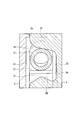
ストッパ収容部14には、第1段部21と、第2段部22と、第3段部23とが形成されている。第1段部21は、ロック挿通孔2a内面上のストッパ収容部14の開口部における、ロック部材4のアンロック側(図4の上方向)に位置する。第2段部22は、上述した開口部における、ロック部材4のロック側(図4の下方向)に位置する。第3段部23は、上述した開口部における、側方(図6の左右方向)に位置する。第1段部21、第2段部22、及び、第3段部23には、ストッパピン12が係合可能である。なお、ロック部材4のスライド方向とストッパピン12のスライド方向との双方に対して直交する方向を第1方向と定義すると、第3段部23は、上述した開口部における、第1方向(図6の左右方向)に位置する。
図1にし召されるように、ロック部材4は、硬質な板部材であり、係合端部4bと、バネ受部4cとが形成されている。係合端部4bは、ロック部材4の先端に形成されており、ステアリングシャフトと係合し得る。バネ受部4cは、ロック部材4の基端に形成されており、巻バネ6と当接する。ロック部材4は、メインフレーム2に形成されたロック挿通孔2a内に配設されている。ロック部材4は、ステアリングシャフトの回転を阻止するロック位置とステアリングシャフトの回転を許容するアンロック位置との間でスライド可能である。
また、ロック部材4には、ピン挿通部4aが形成されている。ピン挿通部4aは、ロック部材4を板厚方向(ストッパピン12のスライド方向)に貫通するように形成されている。本実施形態では、ピン挿通部4aは、ロック部材4のスライド方向に沿う側縁に切り欠きとして形成されている(図7参照)。ピン挿通部4aのロック側(図7下方)の内面には、上述した第1方向に沿って傾斜する傾斜部4dが設けられている。傾斜部4dの中央部分は、ロック側からアンロック側(図7上方)に向けて突出する山形に形成されている。なお、ピン挿通部4aは、本実施形態では切り欠きとして形成されているが、貫通孔として形成されていても良い。
図1に示されるように、ストッパ7は、サブフレーム11と、ストッパピン12と、ストッパバネ13とから構成されている。サブフレーム11は、円筒状のストッパ収容部14を備えている。サブフレーム11は、メインフレーム2に装着される。ストッパ収容部14は、サブフレーム11がメインフレーム2に装着された状態でロック挿通孔2aと直交する。ストッパピン12及びストッパバネ13が、ストッパ収容部14内に収容される。
図4及び図5に示されるように、ストッパピン12は、底を有する円筒形状を有している。ストッパピン12は、ストッパ収容部14内に位置するアンラッチ位置(図4)とストッパ収容部14外に位置するラッチ位置(図5)との間をスライドする。ストッパピン12の内部にはストッパバネ(本実施形態では巻バネ)13が収容される。ストッパピン12は、ストッパバネ13によってアンラッチ位置からラッチ位置に向けて(図4の右方向)付勢されている。ストッパピン12がアンラッチ位置にあるときは、ロック部材4がどの位置にあってもストッパピン12とロック部材4とは係合しない(図4参照)。一方、ストッパピン12がラッチ位置にあるときは、ストッパピン12はロック位置のロック部材4のピン挿通部4a内に位置する(図5参照)。
図4に示されるように、トリガー8は、メインフレーム2に対して着脱可能である。トリガー8は、通常時にはメインフレーム2に設けられたトリガー挿通孔2bに挿入されている。トリガー8がトリガー挿通孔2bに挿入された状態では、トリガー8の先端8aはストッパ収容部14内のストッパピン12の端面12aと係合しており、ストッパピン12はアンラッチ位置に保持されている。このとき、ストッパバネ13は、ストッパピン12内部で圧縮されている。
次に、前記ステアリングロック装置1の動作を説明する。ロック部材4がロック位置にあってステアリングシャフトをロックしているときは、ストッパ7がトリガー8によって非作動状態に保持されている(図4参照)。カバー3をメインフレーム2から取り外すと、カバー3と一体に形成されたトリガー8、及び、巻バネ6も取り外される。この結果、トリガー8の先端とストッパピン12との係合が解除され、ストッパピン12がストッパバネ13によってラッチ位置に移動される。ストッパピン12は、ロック部材4のピン挿通部4aに嵌入される(図5参照)。この状態下でロック部材4を引抜こうとしても、ストッパピン12とロック部材4とが係合し、ストッパピン12の両端が第1段部21に引っかかるので、ロック部材4は抜取られることなくロック位置に保持される。
また、上述した状態下で、トリガー挿通孔2bを通じてストッパバネ13が取除かれると、ストッパピン12は、落下して第2段部22と係合する。そして、ストッパピン12と第2段部22との係合によってストッパピン12はアンラッチ位置の移動が抑止され、ラッチ位置に保持される。したがって、ストッパピン12とロック部材4との係合は保持され、ロック部材4は抜取られることなくロック位置に保持される(図5~図7参照)。
さらに、ロック部材4を動かしてストッパピン12を持ち上げることでロック部材4と第2段部22との係合を外してストッパピン12をアンラッチ位置に移動させようとしても、ストッパピン12傾斜部4dによって第3段部23に押し出される(図9参照)。ストッパピン12は、第3段部23に引っかかるので、アンラッチ位置に移動されることはない。また、振動を与えてストッパピン12を移動させようとしても、ストッパピン12は傾斜部4dの山形形状によって反対側の斜面に移動してしまう。このため、振動を与えてもストッパピン12はアンラッチ位置に移動されず、ラッチ位置に保持される。このように、ストッパピン12とロック部材4との係合は確実に保持され、ロック部材4は抜取られることなくロック位置に保持される。
以上、本発明では、カバー3をメインフレーム2から取り外した場合のみならず、ストッパバネ13を取除いた場合でも、ストッパピン12と各段部21,22,23とが係合してロック部材4をロック位置に保持する。この結果、ロック部材4の不正なアンロックが阻止され、駐車中における車両盗難が防止され得る。
上記実施形態では、各段部が、ストッパ収容部の開口部の周囲、および、該開口部と対向するロック挿通孔の壁面に設けられている。このような単純な構成によって、部品点数を増加させることなく、不正なアンロックを防止することができる。
また、ピン挿通部4aに上述した第1方向に沿って傾斜する山形の傾斜部4dを設け、かつ、ストッパピン12をほぼ円筒形とすることで、ストッパバネ13を取除いてロック部材4をアンロック位置へ移動させようとしてもストッパピン12を傾斜部4dによって第1方向へ変位させて第3段部23と係合させることができる。このため、ストッパピン12をアンロック位置に移動させることができず、ロック部材4はロック位置に保持される。従って、ロック部材4の不正なアンロックをより一層確実に阻止でき、駐車中における車両盗難をより一層防止できる。さらに、ストッパピン12は山形の傾斜部4dの頂点上に留まることはないので、ストッパピン12をアンロック位置に移動させることができず、ロック部材はロック位置に確実に保持される。これによって、ロック部材の不正なアンロックをより一層阻止できる。
以上、本発明の好適な実施形態について説明したが、本発明は上記実施形態には限定されず、種々の変形が可能である。例えば、上記実施形態では、トリガー8はカバー3と一体的に形成されたが、トリガー8と巻バネ6とが一体に形成されてもよい。
Claims (6)
- ステアリングロック装置であって、
メインフレームに形成されたロック挿通孔内に配設され、ステアリングシャフトの回転を阻止するロック位置とステアリングシャフトの回転を許容するアンロック位置との間でスライド可能なロック部材と、
前記ロック部材に形成されたピン挿通部と、
該メインフレームに形成されたストッパ収容部に収容され、前記ロック部材のスライドを許容するアンラッチ位置と前記ピン挿通部と係合して前記ロック部材を前記ロック位置に保持するラッチ位置との間でスライド可能で、前記ストッパ収容部に収容されたストッパバネによって前記アンラッチ位置から前記ラッチ位置に向けて付勢されているストッパピンと、
該メインフレームに着脱自在に配設され、前記ストッパピンと係合して該ストッパピンをアンラッチ位置に保持するトリガーと、を備え、
前記ストッパ収容部の開口周囲、および、該開口と対向するロック挿通孔壁面の前記アンロック位置側に、前記ラッチ位置に位置する前記ストッパピンと係合する第1段部が設けられている。 - 請求項1に記載のステアリングロック装置であって、
前記ストッパ収容部の開口周囲、および、該開口と対向するロック挿通孔壁面の前記ロック位置側に、前記ラッチ位置に位置する前記ストッパピンと係合する第2段部が設けられている。 - 請求項1に記載のステアリングロック装置であって、
前記ロック部材のスライド方向と前記ストッパピンのスライド方向との双方に直交する方向とを第1方向とし、
前記ストッパ収容部の開口周囲、および、該開口と対向するロック挿通孔壁面の前記第1方向側に、前記ラッチ位置に位置する前記ストッパピンと係合する第3段部が設けられており、
前記ロック部材のピン挿通部に、前記第1方向に沿って傾斜する傾斜部が設けられている。 - 請求項2に記載のステアリングロック装置であって、
前記ロック部材のスライド方向と前記ストッパピンのスライド方向との双方に直交する方向とを第1方向とし、
前記ストッパ収容部の開口周囲、および、該開口と対向するロック挿通孔壁面の前記第1方向側に、前記ラッチ位置に位置する前記ストッパピンと係合する第3段部が設けられており、
前記ロック部材のピン挿通部に、前記第1方向に沿って傾斜する傾斜部が設けられている。 - 請求項3記載のステアリングロック装置であって、
前記ストッパピンが、ほぼ円柱状の外形を有し、
前記傾斜部の中央部分が、前記ロック位置から前記アンロック位置に向けて突出された山形形状を有している。 - 請求項4記載のステアリングロック装置であって、
前記ストッパピンが、ほぼ円柱状の外形を有し、
前記傾斜部の中央部分が、前記ロック位置から前記アンロック位置に向けて突出された山形形状を有している。
Priority Applications (2)
| Application Number | Priority Date | Filing Date | Title |
|---|---|---|---|
| US13/062,959 US8646295B2 (en) | 2008-09-12 | 2009-09-11 | Steering lock device |
| EP20090813136 EP2330000B1 (en) | 2008-09-12 | 2009-09-11 | Steering lock device |
Applications Claiming Priority (2)
| Application Number | Priority Date | Filing Date | Title |
|---|---|---|---|
| JP2008235005A JP5385571B2 (ja) | 2008-09-12 | 2008-09-12 | ステアリングロック装置 |
| JP2008-235005 | 2008-09-12 |
Publications (1)
| Publication Number | Publication Date |
|---|---|
| WO2010029990A1 true WO2010029990A1 (ja) | 2010-03-18 |
Family
ID=42005240
Family Applications (1)
| Application Number | Title | Priority Date | Filing Date |
|---|---|---|---|
| PCT/JP2009/065901 WO2010029990A1 (ja) | 2008-09-12 | 2009-09-11 | ステアリングロック装置 |
Country Status (4)
| Country | Link |
|---|---|
| US (1) | US8646295B2 (ja) |
| EP (1) | EP2330000B1 (ja) |
| JP (1) | JP5385571B2 (ja) |
| WO (1) | WO2010029990A1 (ja) |
Cited By (2)
| Publication number | Priority date | Publication date | Assignee | Title |
|---|---|---|---|---|
| WO2013161466A1 (ja) * | 2012-04-27 | 2013-10-31 | 株式会社 アルファ | ステアリングロック装置 |
| WO2013161465A1 (ja) * | 2012-04-27 | 2013-10-31 | 株式会社 アルファ | ステアリングロック装置 |
Families Citing this family (13)
| Publication number | Priority date | Publication date | Assignee | Title |
|---|---|---|---|---|
| DE102007034481A1 (de) * | 2007-07-20 | 2009-01-22 | Huf Hülsbeck & Fürst Gmbh & Co. Kg | Verriegelungsvorrichtung mit Arretierungsteil |
| US8424348B2 (en) * | 2010-01-27 | 2013-04-23 | Strattec Security Corporation | Steering lock |
| US20140069224A1 (en) | 2012-09-07 | 2014-03-13 | Strattec Security Corporation | Steering lock |
| FR2978403A1 (fr) * | 2011-07-25 | 2013-02-01 | Valeo Securite Habitacle | Dispositif antivol pour colonne de direction et colonne de direction associee |
| JP5935115B2 (ja) * | 2011-11-28 | 2016-06-15 | 株式会社ユーシン | 電動ステアリングロック装置 |
| FR2984822B1 (fr) * | 2011-12-21 | 2014-04-11 | Valeo Securite Habitacle | Antivol de direction pour vehicule automobile a supercondamnation et procede de montage associe |
| US8966948B2 (en) * | 2012-12-03 | 2015-03-03 | Hyundai Motor Company | Electrical steering column lock |
| JP5986909B2 (ja) * | 2012-12-05 | 2016-09-06 | 株式会社アルファ | ステアリングロック装置 |
| ITTO20130766A1 (it) * | 2013-09-23 | 2015-03-24 | Trw Automotive Italia S R L | Bloccasterzo meccanico per veicoli |
| EP3053786B1 (en) * | 2013-10-03 | 2017-11-08 | Alpha Corporation | Steering lock device |
| JP6258125B2 (ja) * | 2014-05-27 | 2018-01-10 | 株式会社アルファ | ステアリングロック装置 |
| JP6355510B2 (ja) * | 2014-09-30 | 2018-07-11 | 株式会社ユーシン | ステアリングロック装置 |
| JP7002373B2 (ja) * | 2018-03-13 | 2022-01-20 | 本田技研工業株式会社 | 車両用部品の取付構造 |
Citations (3)
| Publication number | Priority date | Publication date | Assignee | Title |
|---|---|---|---|---|
| JPH11310104A (ja) * | 1998-04-27 | 1999-11-09 | Toyota Motor Corp | ステアリングロック装置 |
| WO2008056728A1 (fr) * | 2006-11-10 | 2008-05-15 | Alpha Corporation | Dispositif antivol sur la direction |
| JP2008238949A (ja) * | 2007-03-27 | 2008-10-09 | Alpha Corp | ステアリングロック装置 |
Family Cites Families (8)
| Publication number | Priority date | Publication date | Assignee | Title |
|---|---|---|---|---|
| US1542560A (en) * | 1921-06-03 | 1925-06-16 | William D Krautter | Lock |
| US2295807A (en) * | 1941-09-22 | 1942-09-15 | Houdaille Hershey Corp | Steering post and ignition lock assembly |
| US2343976A (en) * | 1941-12-19 | 1944-03-14 | Briggs & Stratton Corp | Combined steering post and ignition lock |
| JPH0412842Y2 (ja) * | 1986-07-14 | 1992-03-26 | ||
| US5415019A (en) * | 1993-04-08 | 1995-05-16 | Perez; Roberto | Steering column locking apparatus |
| US6516640B2 (en) * | 2000-12-05 | 2003-02-11 | Strattec Security Corporation | Steering column lock apparatus and method |
| DE10247803B3 (de) * | 2002-10-14 | 2004-01-29 | Huf Hülsbeck & Fürst Gmbh & Co. Kg | Vorrichtung zum Sperren der Lenkspindel eines Kraftfahrzeugs |
| US7140213B2 (en) * | 2004-02-21 | 2006-11-28 | Strattec Security Corporation | Steering column lock apparatus and method |
-
2008
- 2008-09-12 JP JP2008235005A patent/JP5385571B2/ja not_active Expired - Fee Related
-
2009
- 2009-09-11 WO PCT/JP2009/065901 patent/WO2010029990A1/ja active Application Filing
- 2009-09-11 US US13/062,959 patent/US8646295B2/en not_active Expired - Fee Related
- 2009-09-11 EP EP20090813136 patent/EP2330000B1/en not_active Not-in-force
Patent Citations (3)
| Publication number | Priority date | Publication date | Assignee | Title |
|---|---|---|---|---|
| JPH11310104A (ja) * | 1998-04-27 | 1999-11-09 | Toyota Motor Corp | ステアリングロック装置 |
| WO2008056728A1 (fr) * | 2006-11-10 | 2008-05-15 | Alpha Corporation | Dispositif antivol sur la direction |
| JP2008238949A (ja) * | 2007-03-27 | 2008-10-09 | Alpha Corp | ステアリングロック装置 |
Cited By (6)
| Publication number | Priority date | Publication date | Assignee | Title |
|---|---|---|---|---|
| WO2013161466A1 (ja) * | 2012-04-27 | 2013-10-31 | 株式会社 アルファ | ステアリングロック装置 |
| WO2013161465A1 (ja) * | 2012-04-27 | 2013-10-31 | 株式会社 アルファ | ステアリングロック装置 |
| JP2013230728A (ja) * | 2012-04-27 | 2013-11-14 | Alpha Corp | ステアリングロック装置 |
| CN104245439A (zh) * | 2012-04-27 | 2014-12-24 | 株式会社阿尔发 | 转向锁定装置 |
| US9073507B2 (en) | 2012-04-27 | 2015-07-07 | Alpha Corporation | Steering lock device |
| US9108586B2 (en) | 2012-04-27 | 2015-08-18 | Alpha Corporation | Steering lock device |
Also Published As
| Publication number | Publication date |
|---|---|
| US20110167885A1 (en) | 2011-07-14 |
| JP2010064692A (ja) | 2010-03-25 |
| JP5385571B2 (ja) | 2014-01-08 |
| US8646295B2 (en) | 2014-02-11 |
| EP2330000B1 (en) | 2015-04-22 |
| EP2330000A4 (en) | 2013-02-27 |
| EP2330000A1 (en) | 2011-06-08 |
Similar Documents
| Publication | Publication Date | Title |
|---|---|---|
| WO2010029990A1 (ja) | ステアリングロック装置 | |
| JP5956819B2 (ja) | ステアリングロック装置 | |
| JP5114322B2 (ja) | ステアリングロック装置 | |
| JP5965202B2 (ja) | ステアリングロック装置 | |
| JP4777204B2 (ja) | キー装置 | |
| JP2008222001A (ja) | ステアリングロック装置 | |
| JP2005220702A (ja) | リモコン装置 | |
| JP4912282B2 (ja) | ステアリングロック装置 | |
| JP2007113332A (ja) | 扉用錠装置 | |
| JP2506972Y2 (ja) | 自動販売機用錠前 | |
| JP2006316614A (ja) | 電動式の南京錠 | |
| JP2007038905A (ja) | 電動ステアリングロック装置 | |
| JP4478528B2 (ja) | ケース用施錠装置 | |
| US6460384B1 (en) | Automatic transmission shift rod lock structure | |
| JP6805468B2 (ja) | ステアリングロック装置 | |
| JP6215180B2 (ja) | ラッチ組立体 | |
| JP4460376B2 (ja) | ケース用施錠装置 | |
| JP6831736B2 (ja) | ステアリングロック装置 | |
| JP5392916B2 (ja) | 開閉扉用ロック装置 | |
| JP5180018B2 (ja) | ステアリングロック装置 | |
| JP4386803B2 (ja) | ステアリングロック装置 | |
| TW202332828A (zh) | 栓鎖 | |
| JP2006045770A (ja) | ケース用施錠装置 | |
| JP2007182693A (ja) | 扉用錠装置 | |
| JP2006027359A (ja) | ステアリングロック装置 |
Legal Events
| Date | Code | Title | Description |
|---|---|---|---|
| 121 | Ep: the epo has been informed by wipo that ep was designated in this application |
Ref document number: 09813136 Country of ref document: EP Kind code of ref document: A1 |
|
| WWE | Wipo information: entry into national phase |
Ref document number: 13062959 Country of ref document: US |
|
| NENP | Non-entry into the national phase |
Ref country code: DE |
|
| WWE | Wipo information: entry into national phase |
Ref document number: 2009813136 Country of ref document: EP |