WO2010024299A1 - 表示装置 - Google Patents
表示装置 Download PDFInfo
- Publication number
- WO2010024299A1 WO2010024299A1 PCT/JP2009/064883 JP2009064883W WO2010024299A1 WO 2010024299 A1 WO2010024299 A1 WO 2010024299A1 JP 2009064883 W JP2009064883 W JP 2009064883W WO 2010024299 A1 WO2010024299 A1 WO 2010024299A1
- Authority
- WO
- WIPO (PCT)
- Prior art keywords
- display device
- liquid crystal
- crystal display
- heat
- display panel
- Prior art date
- Legal status (The legal status is an assumption and is not a legal conclusion. Google has not performed a legal analysis and makes no representation as to the accuracy of the status listed.)
- Ceased
Links
Images







Classifications
-
- G—PHYSICS
- G02—OPTICS
- G02F—OPTICAL DEVICES OR ARRANGEMENTS FOR THE CONTROL OF LIGHT BY MODIFICATION OF THE OPTICAL PROPERTIES OF THE MEDIA OF THE ELEMENTS INVOLVED THEREIN; NON-LINEAR OPTICS; FREQUENCY-CHANGING OF LIGHT; OPTICAL LOGIC ELEMENTS; OPTICAL ANALOGUE/DIGITAL CONVERTERS
- G02F1/00—Devices or arrangements for the control of the intensity, colour, phase, polarisation or direction of light arriving from an independent light source, e.g. switching, gating or modulating; Non-linear optics
- G02F1/01—Devices or arrangements for the control of the intensity, colour, phase, polarisation or direction of light arriving from an independent light source, e.g. switching, gating or modulating; Non-linear optics for the control of the intensity, phase, polarisation or colour
- G02F1/13—Devices or arrangements for the control of the intensity, colour, phase, polarisation or direction of light arriving from an independent light source, e.g. switching, gating or modulating; Non-linear optics for the control of the intensity, phase, polarisation or colour based on liquid crystals, e.g. single liquid crystal display cells
- G02F1/133—Constructional arrangements; Operation of liquid crystal cells; Circuit arrangements
- G02F1/1333—Constructional arrangements; Manufacturing methods
- G02F1/133382—Heating or cooling of liquid crystal cells other than for activation, e.g. circuits or arrangements for temperature control, stabilisation or uniform distribution over the cell
-
- G—PHYSICS
- G02—OPTICS
- G02F—OPTICAL DEVICES OR ARRANGEMENTS FOR THE CONTROL OF LIGHT BY MODIFICATION OF THE OPTICAL PROPERTIES OF THE MEDIA OF THE ELEMENTS INVOLVED THEREIN; NON-LINEAR OPTICS; FREQUENCY-CHANGING OF LIGHT; OPTICAL LOGIC ELEMENTS; OPTICAL ANALOGUE/DIGITAL CONVERTERS
- G02F1/00—Devices or arrangements for the control of the intensity, colour, phase, polarisation or direction of light arriving from an independent light source, e.g. switching, gating or modulating; Non-linear optics
- G02F1/01—Devices or arrangements for the control of the intensity, colour, phase, polarisation or direction of light arriving from an independent light source, e.g. switching, gating or modulating; Non-linear optics for the control of the intensity, phase, polarisation or colour
- G02F1/13—Devices or arrangements for the control of the intensity, colour, phase, polarisation or direction of light arriving from an independent light source, e.g. switching, gating or modulating; Non-linear optics for the control of the intensity, phase, polarisation or colour based on liquid crystals, e.g. single liquid crystal display cells
- G02F1/133—Constructional arrangements; Operation of liquid crystal cells; Circuit arrangements
- G02F1/1333—Constructional arrangements; Manufacturing methods
- G02F1/133308—Support structures for LCD panels, e.g. frames or bezels
-
- G—PHYSICS
- G02—OPTICS
- G02B—OPTICAL ELEMENTS, SYSTEMS OR APPARATUS
- G02B6/00—Light guides; Structural details of arrangements comprising light guides and other optical elements, e.g. couplings
- G02B6/0001—Light guides; Structural details of arrangements comprising light guides and other optical elements, e.g. couplings specially adapted for lighting devices or systems
- G02B6/0011—Light guides; Structural details of arrangements comprising light guides and other optical elements, e.g. couplings specially adapted for lighting devices or systems the light guides being planar or of plate-like form
- G02B6/0033—Means for improving the coupling-out of light from the light guide
- G02B6/005—Means for improving the coupling-out of light from the light guide provided by one optical element, or plurality thereof, placed on the light output side of the light guide
- G02B6/0051—Diffusing sheet or layer
-
- G—PHYSICS
- G02—OPTICS
- G02B—OPTICAL ELEMENTS, SYSTEMS OR APPARATUS
- G02B6/00—Light guides; Structural details of arrangements comprising light guides and other optical elements, e.g. couplings
- G02B6/0001—Light guides; Structural details of arrangements comprising light guides and other optical elements, e.g. couplings specially adapted for lighting devices or systems
- G02B6/0011—Light guides; Structural details of arrangements comprising light guides and other optical elements, e.g. couplings specially adapted for lighting devices or systems the light guides being planar or of plate-like form
- G02B6/0081—Mechanical or electrical aspects of the light guide and light source in the lighting device peculiar to the adaptation to planar light guides, e.g. concerning packaging
- G02B6/0085—Means for removing heat created by the light source from the package
-
- G—PHYSICS
- G02—OPTICS
- G02F—OPTICAL DEVICES OR ARRANGEMENTS FOR THE CONTROL OF LIGHT BY MODIFICATION OF THE OPTICAL PROPERTIES OF THE MEDIA OF THE ELEMENTS INVOLVED THEREIN; NON-LINEAR OPTICS; FREQUENCY-CHANGING OF LIGHT; OPTICAL LOGIC ELEMENTS; OPTICAL ANALOGUE/DIGITAL CONVERTERS
- G02F1/00—Devices or arrangements for the control of the intensity, colour, phase, polarisation or direction of light arriving from an independent light source, e.g. switching, gating or modulating; Non-linear optics
- G02F1/01—Devices or arrangements for the control of the intensity, colour, phase, polarisation or direction of light arriving from an independent light source, e.g. switching, gating or modulating; Non-linear optics for the control of the intensity, phase, polarisation or colour
- G02F1/13—Devices or arrangements for the control of the intensity, colour, phase, polarisation or direction of light arriving from an independent light source, e.g. switching, gating or modulating; Non-linear optics for the control of the intensity, phase, polarisation or colour based on liquid crystals, e.g. single liquid crystal display cells
- G02F1/133—Constructional arrangements; Operation of liquid crystal cells; Circuit arrangements
- G02F1/1333—Constructional arrangements; Manufacturing methods
- G02F1/133308—Support structures for LCD panels, e.g. frames or bezels
- G02F1/133317—Intermediate frames, e.g. between backlight housing and front frame
-
- G—PHYSICS
- G02—OPTICS
- G02F—OPTICAL DEVICES OR ARRANGEMENTS FOR THE CONTROL OF LIGHT BY MODIFICATION OF THE OPTICAL PROPERTIES OF THE MEDIA OF THE ELEMENTS INVOLVED THEREIN; NON-LINEAR OPTICS; FREQUENCY-CHANGING OF LIGHT; OPTICAL LOGIC ELEMENTS; OPTICAL ANALOGUE/DIGITAL CONVERTERS
- G02F1/00—Devices or arrangements for the control of the intensity, colour, phase, polarisation or direction of light arriving from an independent light source, e.g. switching, gating or modulating; Non-linear optics
- G02F1/01—Devices or arrangements for the control of the intensity, colour, phase, polarisation or direction of light arriving from an independent light source, e.g. switching, gating or modulating; Non-linear optics for the control of the intensity, phase, polarisation or colour
- G02F1/13—Devices or arrangements for the control of the intensity, colour, phase, polarisation or direction of light arriving from an independent light source, e.g. switching, gating or modulating; Non-linear optics for the control of the intensity, phase, polarisation or colour based on liquid crystals, e.g. single liquid crystal display cells
- G02F1/133—Constructional arrangements; Operation of liquid crystal cells; Circuit arrangements
- G02F1/1333—Constructional arrangements; Manufacturing methods
- G02F1/1335—Structural association of cells with optical devices, e.g. polarisers or reflectors
- G02F1/133528—Polarisers
-
- G—PHYSICS
- G02—OPTICS
- G02F—OPTICAL DEVICES OR ARRANGEMENTS FOR THE CONTROL OF LIGHT BY MODIFICATION OF THE OPTICAL PROPERTIES OF THE MEDIA OF THE ELEMENTS INVOLVED THEREIN; NON-LINEAR OPTICS; FREQUENCY-CHANGING OF LIGHT; OPTICAL LOGIC ELEMENTS; OPTICAL ANALOGUE/DIGITAL CONVERTERS
- G02F1/00—Devices or arrangements for the control of the intensity, colour, phase, polarisation or direction of light arriving from an independent light source, e.g. switching, gating or modulating; Non-linear optics
- G02F1/01—Devices or arrangements for the control of the intensity, colour, phase, polarisation or direction of light arriving from an independent light source, e.g. switching, gating or modulating; Non-linear optics for the control of the intensity, phase, polarisation or colour
- G02F1/13—Devices or arrangements for the control of the intensity, colour, phase, polarisation or direction of light arriving from an independent light source, e.g. switching, gating or modulating; Non-linear optics for the control of the intensity, phase, polarisation or colour based on liquid crystals, e.g. single liquid crystal display cells
- G02F1/133—Constructional arrangements; Operation of liquid crystal cells; Circuit arrangements
- G02F1/1333—Constructional arrangements; Manufacturing methods
- G02F1/1335—Structural association of cells with optical devices, e.g. polarisers or reflectors
- G02F1/1336—Illuminating devices
- G02F1/133628—Illuminating devices with cooling means
-
- G—PHYSICS
- G02—OPTICS
- G02F—OPTICAL DEVICES OR ARRANGEMENTS FOR THE CONTROL OF LIGHT BY MODIFICATION OF THE OPTICAL PROPERTIES OF THE MEDIA OF THE ELEMENTS INVOLVED THEREIN; NON-LINEAR OPTICS; FREQUENCY-CHANGING OF LIGHT; OPTICAL LOGIC ELEMENTS; OPTICAL ANALOGUE/DIGITAL CONVERTERS
- G02F1/00—Devices or arrangements for the control of the intensity, colour, phase, polarisation or direction of light arriving from an independent light source, e.g. switching, gating or modulating; Non-linear optics
- G02F1/01—Devices or arrangements for the control of the intensity, colour, phase, polarisation or direction of light arriving from an independent light source, e.g. switching, gating or modulating; Non-linear optics for the control of the intensity, phase, polarisation or colour
- G02F1/13—Devices or arrangements for the control of the intensity, colour, phase, polarisation or direction of light arriving from an independent light source, e.g. switching, gating or modulating; Non-linear optics for the control of the intensity, phase, polarisation or colour based on liquid crystals, e.g. single liquid crystal display cells
- G02F1/133—Constructional arrangements; Operation of liquid crystal cells; Circuit arrangements
- G02F1/1333—Constructional arrangements; Manufacturing methods
- G02F1/1339—Gaskets; Spacers; Sealing of cells
-
- H—ELECTRICITY
- H04—ELECTRIC COMMUNICATION TECHNIQUE
- H04N—PICTORIAL COMMUNICATION, e.g. TELEVISION
- H04N5/00—Details of television systems
- H04N5/64—Constructional details of receivers, e.g. cabinets or dust covers
-
- H—ELECTRICITY
- H05—ELECTRIC TECHNIQUES NOT OTHERWISE PROVIDED FOR
- H05K—PRINTED CIRCUITS; CASINGS OR CONSTRUCTIONAL DETAILS OF ELECTRIC APPARATUS; MANUFACTURE OF ASSEMBLAGES OF ELECTRICAL COMPONENTS
- H05K7/00—Constructional details common to different types of electric apparatus
- H05K7/20—Modifications to facilitate cooling, ventilating, or heating
-
- G—PHYSICS
- G02—OPTICS
- G02F—OPTICAL DEVICES OR ARRANGEMENTS FOR THE CONTROL OF LIGHT BY MODIFICATION OF THE OPTICAL PROPERTIES OF THE MEDIA OF THE ELEMENTS INVOLVED THEREIN; NON-LINEAR OPTICS; FREQUENCY-CHANGING OF LIGHT; OPTICAL LOGIC ELEMENTS; OPTICAL ANALOGUE/DIGITAL CONVERTERS
- G02F1/00—Devices or arrangements for the control of the intensity, colour, phase, polarisation or direction of light arriving from an independent light source, e.g. switching, gating or modulating; Non-linear optics
- G02F1/01—Devices or arrangements for the control of the intensity, colour, phase, polarisation or direction of light arriving from an independent light source, e.g. switching, gating or modulating; Non-linear optics for the control of the intensity, phase, polarisation or colour
- G02F1/13—Devices or arrangements for the control of the intensity, colour, phase, polarisation or direction of light arriving from an independent light source, e.g. switching, gating or modulating; Non-linear optics for the control of the intensity, phase, polarisation or colour based on liquid crystals, e.g. single liquid crystal display cells
- G02F1/133—Constructional arrangements; Operation of liquid crystal cells; Circuit arrangements
- G02F1/1333—Constructional arrangements; Manufacturing methods
- G02F1/133302—Rigid substrates, e.g. inorganic substrates
-
- G—PHYSICS
- G02—OPTICS
- G02F—OPTICAL DEVICES OR ARRANGEMENTS FOR THE CONTROL OF LIGHT BY MODIFICATION OF THE OPTICAL PROPERTIES OF THE MEDIA OF THE ELEMENTS INVOLVED THEREIN; NON-LINEAR OPTICS; FREQUENCY-CHANGING OF LIGHT; OPTICAL LOGIC ELEMENTS; OPTICAL ANALOGUE/DIGITAL CONVERTERS
- G02F1/00—Devices or arrangements for the control of the intensity, colour, phase, polarisation or direction of light arriving from an independent light source, e.g. switching, gating or modulating; Non-linear optics
- G02F1/01—Devices or arrangements for the control of the intensity, colour, phase, polarisation or direction of light arriving from an independent light source, e.g. switching, gating or modulating; Non-linear optics for the control of the intensity, phase, polarisation or colour
- G02F1/13—Devices or arrangements for the control of the intensity, colour, phase, polarisation or direction of light arriving from an independent light source, e.g. switching, gating or modulating; Non-linear optics for the control of the intensity, phase, polarisation or colour based on liquid crystals, e.g. single liquid crystal display cells
- G02F1/133—Constructional arrangements; Operation of liquid crystal cells; Circuit arrangements
- G02F1/1333—Constructional arrangements; Manufacturing methods
- G02F1/133308—Support structures for LCD panels, e.g. frames or bezels
- G02F1/133314—Back frames
-
- G—PHYSICS
- G02—OPTICS
- G02F—OPTICAL DEVICES OR ARRANGEMENTS FOR THE CONTROL OF LIGHT BY MODIFICATION OF THE OPTICAL PROPERTIES OF THE MEDIA OF THE ELEMENTS INVOLVED THEREIN; NON-LINEAR OPTICS; FREQUENCY-CHANGING OF LIGHT; OPTICAL LOGIC ELEMENTS; OPTICAL ANALOGUE/DIGITAL CONVERTERS
- G02F1/00—Devices or arrangements for the control of the intensity, colour, phase, polarisation or direction of light arriving from an independent light source, e.g. switching, gating or modulating; Non-linear optics
- G02F1/01—Devices or arrangements for the control of the intensity, colour, phase, polarisation or direction of light arriving from an independent light source, e.g. switching, gating or modulating; Non-linear optics for the control of the intensity, phase, polarisation or colour
- G02F1/13—Devices or arrangements for the control of the intensity, colour, phase, polarisation or direction of light arriving from an independent light source, e.g. switching, gating or modulating; Non-linear optics for the control of the intensity, phase, polarisation or colour based on liquid crystals, e.g. single liquid crystal display cells
- G02F1/133—Constructional arrangements; Operation of liquid crystal cells; Circuit arrangements
- G02F1/1333—Constructional arrangements; Manufacturing methods
- G02F1/133308—Support structures for LCD panels, e.g. frames or bezels
- G02F1/13332—Front frames
Definitions
- the present invention relates to a display device.
- a liquid crystal display (LCD: Liquid Crystal Display) provided in a conventional liquid crystal display device has a color filter substrate colored with red, green, and blue, a liquid crystal panel having a liquid crystal layer, and the back side of the liquid crystal panel. It is comprised by the backlight etc. which are arrange
- the twist of the liquid crystal molecules in the liquid crystal layer is controlled by changing the voltage, and the white light of the backlight transmitted through the liquid crystal layer according to the twist of the liquid crystal molecules is colored in each color filter Pass through.
- the white light of the backlight passes through the color filter, it becomes red, green, and blue light, and an image is displayed.
- CCFL Cold Cathode Fluorescent Lighting
- LEDs Light Emitting Diodes
- the heat generated by the light source must be efficiently dissipated.
- a fan is provided inside the liquid crystal display device in order to efficiently dissipate the heat generated by the light source, power is required to operate the fan, and the fan makes it difficult to reduce the thickness of the device. was there.
- a method of providing a heat dissipation fin inside the liquid crystal display device instead of a fan has been proposed.
- a heat dissipation fin is provided inside the liquid crystal display device. Even if it was provided, it was not difficult to make the device thinner.
- the present invention has been made in view of the above problems, and an object of the present invention is to generate heat generated by the heat source when the heat source is arranged on at least one side of the display panel. It is an object of the present invention to provide a new and improved display device capable of effectively diverging.
- a display panel for displaying an image, a heat source provided on a side surface of at least one side of the display panel, and an endothermic part for absorbing heat generated by the heat source; , Provided on the back side of the display panel, made of metal, a part of which is in close contact with the heat absorption part, and a front plate made of metal, provided on the front side of the display panel, between the front plate and the heat absorption part And a middle chassis provided on the display.
- the display panel displays an image
- the heat source is provided on the side surface of at least one side of the display panel
- the heat absorption unit absorbs heat generated by the heat source.
- the back plate is provided on the back side of the display panel and is made of metal, and a part thereof is in close contact with the heat absorbing portion
- the front plate is provided on the front side of the display panel and is made of metal.
- the middle chassis is provided between the front plate and the heat absorbing part.
- the middle chassis may be made of a material having a thermal conductivity lower than that of the heat absorbing part.
- a panel control board for controlling the driving of the display panel may be further provided, and the panel control board may be located at the back center portion of the back plate.
- a panel driver board that controls display of an image on the display panel; and a flexible board that connects between the panel control board and the panel driver board, and the back plate has a width, length, and thickness of the flexible board. You may provide the recessed part which has a corresponding hollow and lets a flexible substrate pass.
- the peripheral portion of the front plate may have a tapered portion such that the back side becomes smaller from the front side to the back side.
- the heat source may further include a light irradiation unit that emits visible light, diffuses light emitted from the heat source, irradiates the display panel, and displays an image on the display panel.
- the present invention when a heat source such as an LED is disposed on at least one side of the display panel, it is possible to effectively dissipate heat generated by the heat source.
- the object is to provide a new and improved display device.
- FIG. 1 is an explanatory view showing a liquid crystal display device 100 according to an embodiment of the present invention from the front.
- FIG. 2 is an explanatory view showing the liquid crystal display device 100 according to one embodiment of the present invention from the side.
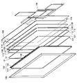
- FIG. 3 is an exploded perspective view of the liquid crystal display device 100 according to the embodiment of the present invention.
- FIG. 4 is an explanatory diagram for explaining the outline of the substrate arrangement of the liquid crystal display device 100 according to the embodiment of the present invention.
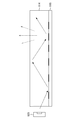
- FIG. 5 is an explanatory diagram for explaining the positional relationship between the light source 112, the light guide plate 114, and the reflection plate 115.
- FIG. 6 is an explanatory diagram for explaining the positional relationship among the light source 112, the light guide plate 114, and the reflection plate 115.
- FIG. 1 is an explanatory view showing a liquid crystal display device 100 according to an embodiment of the present invention from the front.
- FIG. 2 is an explanatory view showing the liquid crystal display device 100 according to one embodiment of the present invention from the
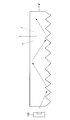
- FIG. 7 is an explanatory diagram showing the light guide plate 114 ′ having a reflective shape formed on the back side.
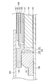
- FIG. 8 is an explanatory diagram illustrating a configuration of a heat dissipation mechanism for heat generated from the light source 112 with a cross-sectional view.
- FIG. 9A is an explanatory view illustrating the shape of the rear cover 106 in the liquid crystal display device 100 according to the embodiment of the present invention.
- FIG. 9B is an explanatory view illustrating the shape of the rear cover 106 in the liquid crystal display device 100 according to the embodiment of the present invention.
- FIG. 9C is an explanatory view illustrating the shape of the rear cover 106 in the liquid crystal display device 100 according to the embodiment of the present invention.
- FIG. 9A is an explanatory view illustrating the shape of the rear cover 106 in the liquid crystal display device 100 according to the embodiment of the present invention.
- FIG. 9B is an explanatory view illustrating the shape of the rear cover 106 in the liquid crystal display device 100
- FIG. 10A is an explanatory view showing the shape of the peripheral edge portion of the front bezel 104 in the liquid crystal display device 100 according to the embodiment of the present invention in a perspective view.
- FIG. 10B is an explanatory diagram showing cross-sectional shapes of the front bezel 104 and the rear cover 106 in the liquid crystal display device 100 according to the embodiment of the present invention.
- FIG. 10C is an explanatory diagram showing cross-sectional shapes of the front bezel 104 and the rear cover 106 in the liquid crystal display device 100 according to the embodiment of the present invention.
- FIG. 11 is an explanatory diagram illustrating a connection structure between the chassis 108 and the stand 110 in the liquid crystal display device 100 according to the embodiment of the present invention.
- FIG. 12 is an explanatory diagram illustrating a connection structure between the chassis 108 and the stand 110 in the liquid crystal display device 100 according to the embodiment of the present invention.
- FIG. 1 is an explanatory view showing a liquid crystal display device 100 according to an embodiment of the present invention from the front
- FIG. 2 is an explanatory view showing a liquid crystal display device 100 according to an embodiment of the present invention from the side.
- the appearance of the liquid crystal display device 100 according to an embodiment of the present invention will be described with reference to FIGS. 1 and 2.
- the liquid crystal display device 100 is an example of the display device of the present invention. Light is applied to a display panel having a liquid crystal layer, and voltage is applied to the liquid crystal molecules in the liquid crystal layer to change the direction of the liquid crystal molecules. A shutter is realized and an image is displayed.
- the liquid crystal display device 100 according to an embodiment of the present invention includes a display panel 102, a front bezel 104, a rear cover 106, a chassis 108, and a stand 110. Composed.
- the front bezel 104 side is referred to as the front side
- the rear cover 106 side is referred to as the back side.
- the display panel 102 displays moving images or still images (hereinafter collectively referred to simply as “images”).
- the display panel 102 includes a liquid crystal layer in which liquid crystal molecules are encapsulated, a glass substrate for applying a voltage to the liquid crystal molecules, a polarizing plate that polarizes white light emitted from a light source, and white light emitted from the polarizing plate. And a color filter for coloring.
- the display panel 102 is not limited to the configuration described above, and may be a liquid crystal panel having various configurations conventionally provided. The configuration of the display panel 102 according to the present embodiment will be described in detail later.
- the front bezel 104 is an example of the front plate of the present invention, and is a frame for fixing the display panel 102 provided on the front side of the display panel 102. Note that the front bezel 104 is provided with an opening, and an image displayed on the display panel 102 can be viewed through the opening.
- the rear cover 106 is an example of the back plate of the present invention, and is a cover for fixing the display panel 102 provided on the back side of the display panel 102.
- the chassis 108 is provided on the back side of the rear cover 106 and is mounted with various substrates for driving the display panel 102.
- the front bezel 104 and the rear cover 106 are made of a metal having high thermal conductivity, such as aluminum. By forming the front bezel 104 and the rear cover 106 from metal, electromagnetic waves generated from various circuits and electronic components provided in the liquid crystal display device 100 can be shielded. Therefore, unnecessary radiation generated from various circuits and electronic components provided in the liquid crystal display device 100 can be reduced.
- Anodizing may be applied to the front side of the front bezel 104.
- the stand 110 is a stand for fixing and installing the liquid crystal display device 100.
- the stand 110 is configured to be connectable to the chassis 108.
- the chassis 108 can be fixed to the stand 110, and the chassis 108 can be detached from the stand 110 and fixed to the wall. Therefore, the chassis 108 is provided with a fastening portion for fixing to the wall.
- the stand 110 may incorporate a speaker. By incorporating a speaker in the stand 110, sound can be output from the stand 110.
- FIG. 3 is an exploded perspective view of the liquid crystal display device 100 according to the embodiment of the present invention.
- the configuration of the liquid crystal display device 100 according to an embodiment of the present invention will be described with reference to FIG.
- the liquid crystal display device 100 includes a front bezel 104, a rear cover 106, a chassis 108, a display panel 102, a light source 112, a heat sink 130, a light guide plate 114, a reflector 115, And a middle chassis 131.
- the display panel 102 includes a liquid crystal cell 121 and a panel driver substrate 122.
- the light source 112 is provided at a position along the four sides of the display panel 102 as shown in FIG.
- a white LED that emits white light may be used, or an LED that emits light of each of the three primary colors red, blue, and green may be used.
- a light emitting element other than an LED may be used. In the following description, a case where a white LED is used as the light source 112 will be described.
- the white light emitted from the light source 112 provided along the four sides of the display panel 102 is diffused by the light guide plate 114 and reflected by the reflection plate 115 so that the display panel 102 is evenly irradiated.
- the light guide plate 114 is provided on the back side of the display panel 102.
- a silicone rubber resin may be integrally formed by molding.
- a polycarbonate resin (PC) or an acrylic resin which is a transparent thermoplastic resin conventionally used in terms of high permeability, moldability, low water absorption (moisture absorption), environmental resistance, and low birefringence.
- a silicone rubber resin material exhibiting a performance equal to or higher than (polymethyl methacrylate (PMMA)) may be used. Examples of such a silicone rubber resin material include polydimethylsiloxane (PDMS), polyalkylalkenylsiloxane, and polyalkylphenylsiloxane.
- the transparency and refractive index of the light guide plate 114 are appropriate, and as a result, the light guide plate 114 has an excellent function of guiding light.
- the constituent material is polydimethylsiloxane (PDMS)
- the light guide plate 5 is transparent and has a refractive index of 1.4 or more, and has a function of guiding light better than the conventional light guide plate. Become a thing.
- the light guide plate 114 diffuses white light emitted from the light sources 112 provided on the four sides as described above, and irradiates the light toward the display panel 102.
- the light source 112 emits light from the side surface side of the light guide plate 114.
- the light source 112 is an LED that emits light of the three primary colors red, blue, and green
- the light emitted from each LED is mixed in the light guide plate 114 and displayed as white light. You may comprise so that the panel 102 may be irradiated.
- a reflector 115 is provided on the back side of the light guide plate 114.
- an optical sheet is provided on the front side of the light guide plate 114.
- a diffusion material is printed on the back side of the light guide plate 114. The light from the light source 112 is diffused by the diffusing material printed on the back side of the light guide plate 114 and is applied to the display panel 102.
- the liquid crystal cell 121 has a structure in which a liquid crystal layer is sealed between two glass substrates, and the two glass substrates have a structure sandwiched between polarizing plates.
- the alignment state of the liquid crystal layer sealed in the liquid crystal cell 121 changes, so that the liquid crystal cell 121 can pass or block light emitted from the light source 112. it can.
- the middle chassis 131 is a member provided between the front bezel 104 and the heat sink 130.
- the middle chassis 131 may be molded using a material having a lower thermal conductivity than metal, such as a synthetic resin.
- the light source 112 is provided at positions along the four sides of the display panel 102.
- the arrangement of the light source 112 is not limited to this example.
- the light source 112 may be arranged only on one side of the display panel 102, may be arranged only on two sides, or may be arranged only on three sides.
- FIG. 4 is an explanatory diagram for explaining the outline of the substrate arrangement of the liquid crystal display device 100 according to the embodiment of the present invention.
- an outline of the substrate arrangement of the liquid crystal display device 100 according to the embodiment of the present invention will be described with reference to FIG.
- the liquid crystal display device 100 includes a panel control board 151, a panel driver board 122, a signal board 153, a power board 154, an LED driver board 155, It is comprised including. And each board
- the panel control board 151 the signal board 153, the power board 154, and the LED driver board 155 are mounted on the chassis.
- the panel control board 151 is mounted on the center of the back surface of the liquid crystal display device 100 and is connected to the panel driver board 122 and the flexible board 156.
- FIGS. 5 and 6 are explanatory diagrams for explaining the positional relationship among the light source 112, the light guide plate 114, and the reflection plate 115 in the liquid crystal display device 100 according to the embodiment of the present invention.
- the light source 112, the light guide plate 114, and the reflection plate 115 in the liquid crystal display device 100 according to the embodiment of the present invention will be described with reference to FIGS.
- FIG. 5 is a view of the light source 112 and the light guide plate 114 as viewed from the front side of the liquid crystal display device 100
- FIG. 6 is a view of the light source 112, the light guide plate 114, and the reflection plate as viewed from the side surface side of the liquid crystal display device 100. It is a figure which shows the shape of the cross section of 115.
- the light source 112 is provided at a position along each side of the light guide plate 114.
- Each light source 112 includes a plurality of LEDs 123 that emit white light and an LED circuit board 124 for driving the LEDs 123.
- the LED circuit board 124 is, for example, a glass epoxy board or a metal core board such as aluminum, has a substantially rectangular shape, and may be formed in a thin plate shape.
- the LEDs 123 are provided on the LED circuit board 124 in substantially a line in the longitudinal direction.
- the LED circuit board 124 that receives the light emission instruction from the LED driver board 155 controls the LED 123 to emit light, whereby the LED 123 emits white light.
- the LED 123 that emits white light can emit white light toward the light guide plate 114.
- the light guide plate 114 diffuses white light emitted from the LEDs 123 included in the light source 112 and irradiates the display panel 102 with white light.
- a diffusion material is printed on the back side of the light guide plate 114 as shown in FIG.
- a reflector 115 is provided on the back side of the optical plate 114.
- the diffusion material is printed on the back side of the light guide plate 114, and the reflection plate 115 is provided on the back side of the light guide plate 114, thereby efficiently diffusing white light from the light source 112 and irradiating the display panel 102. can do.
- the diffuser is printed on the back side of the light guide plate 114 and the reflection plate 115 is provided on the back side of the light guide plate 114, so that the white light from the light source 112 is efficiently diffused.
- the invention is not limited to such examples.
- a reflective shape may be formed on the back side of the light guide plate to reflect white light from the light source.
- FIG. 7 is an explanatory diagram showing the light guide plate 114 ′ having a reflective shape formed on the back side. By making the back side of the light guide plate 114 ′ as shown in FIG. 7 into an appropriate shape, the white light from the light source 112 can be efficiently diffused and irradiated onto the display panel 102.
- the LEDs 123 are arranged in a row in the light source 112, but it goes without saying that the arrangement of the LEDs is not limited to this example in the present invention.
- the arrangement of the LEDs may be changed as appropriate in accordance with the properties of the LEDs used as the light source and the size of the display panel.
- the configuration of the light source 112, the light guide plate 114, and the reflection plate 115 in the liquid crystal display device 100 according to the embodiment of the present invention has been described above. Next, a heat dissipation mechanism for heat generated from the light source 112 according to an embodiment of the present invention will be described.
- an LED that emits white light can be used as the light source 112.
- the larger the screen size that is, the larger the size of the display panel 102, the more LEDs 123 per row of the light source 112 illuminate the entire display panel 102. It is also necessary to increase the number of Accordingly, the larger the screen size, the more heat generated from the LED 123. Therefore, the light source 112 is an example of the heat source of the present invention.
- the liquid crystal display device 100 needs to efficiently release the heat generated from the LED 123 to suppress an internal temperature rise.
- the heat generated from the light source 112 is absorbed by the heat sink, and the heat absorbed by the heat sink is further released from the front bezel 104 and the rear cover 106, thereby efficiently releasing the heat generated from the LED 123 of the light source 112. It is characterized by letting.
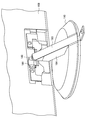
- FIG. 8 is an explanatory diagram illustrating a configuration of a heat dissipation mechanism for heat generated from the light source 112 according to an embodiment of the present invention using a cross-sectional view.
- the configuration of a heat dissipation mechanism for heat generated from the light source 112 according to an embodiment of the present invention will be described with reference to FIG.
- the upper side of the drawing is the front side of the liquid crystal display device 100
- the lower side of the drawing is the back side of the liquid crystal display device 100.
- the light guide plate 114, the optical sheet 117, and the display panel 102 are also illustrated.
- an optical sheet 117 is provided on the front side of the light guide plate 114.
- the light source 112 is provided on the side surface side of the light guide plate 114, and the light from the light source 112 is irradiated on the side surface side of the light guide plate 114.
- the optical sheet 117 is a sheet for performing various optical functions with respect to light emitted from the light source 112 and applied to the display panel 102 through the light guide plate 114.
- the optical sheet 117 is, for example, a functional sheet that decomposes the display light supplied from the LED 123 and incident on the display panel 102 into polarized light components orthogonal to the incident light, and compensates for the phase difference of the light wave to widen the viewing angle and prevent coloration.
- a plurality of optical sheets having various optical functions such as a functional sheet for achieving the above or a functional sheet for diffusing display light may be laminated.
- the display panel 102 includes polarizing plates 161 and 164 and glass substrates 162 and 163.
- the glass substrates 162 and 163 are formed so as to receive a voltage from the panel driver substrate 122.
- the glass substrate 163 on the back side includes a signal line and a scanning line arranged in a matrix on the glass substrate on the back side, a thin film transistor as a switching element arranged at the intersection of the signal line and the scanning line, a pixel electrode May be formed.
- a counter electrode or a color filter may be formed on the glass substrate 162 on the front side.
- a liquid crystal layer is formed between the glass substrates 162 and 163 by enclosing the liquid crystal between the glass substrates 162 and 163.
- the alignment state of the liquid crystal molecules in the liquid crystal layer formed between the glass substrates 162 and 163 can be changed.
- the polarizing plate 161 disposed on the front side of the glass substrate 162 and the polarizing plate 164 disposed on the back side of the glass substrate 163 allow only light in the vibration direction that matches the polarization direction of the polarizing plates 161 and 164 to pass. be able to.
- the heat sink 130 is bonded to the surface of the LED circuit board 124 opposite to the surface on the LED 123 side.
- the heat sink 130 it is desirable to use a metal having excellent thermal conductivity.
- the heat sink 130 may be formed by molding an aluminum block. Needless to say, the shape of the heat sink 130 is not limited to the shape illustrated in FIG. 8.
- the heat sink 130 is provided along each side of the display panel 102 corresponding to the light source 112. Therefore, when the light source 112 is provided only on one side of the display panel 102, the heat sink 130 is also provided only on that side.
- a thermal conductive material having excellent thermal conductivity may be used for bonding the LED circuit board 124 and the heat sink 130.
- a heat conductive material excellent in heat conductivity a double-sided tape using a material excellent in heat conductivity may be used.
- the back side of the heat sink 130 and the front side of the rear cover 106 are bonded.
- a thermal conductive material having excellent thermal conductivity may be used in the same manner as the adhesion between the LED circuit board 124 and the heat sink 130.
- the heat conductive material excellent in thermal conductivity used for bonding the LED circuit board 124 and the heat sink 130 may be a double-sided tape using a material excellent in thermal conductivity.
- the shape of the heat sink 130 is such that, for example, as shown in FIG. 8, the width of the surface in contact with the rear cover 106 is larger than the width of the surface in contact with the LED circuit board 124 in order to efficiently discharge the heat generated in the LED 123. You may form so that becomes longer. By forming the heat sink 130 so that the width of the surface in contact with the rear cover 106 is longer, the heat absorbed from the LED 123 can be efficiently transmitted to the rear cover 106.
- the liquid crystal display device 100 includes a middle chassis 131 on the front side of the heat sink 130.
- the middle chassis 131 may be molded from a material having a lower thermal conductivity than metal, for example, and may be molded using, for example, a synthetic resin as such a material.
- the middle chassis 131 is provided between the front bezel 104 and the heat sink 130.
- the heat absorbed by the heat sink 130 is transmitted to the rear cover 106, and the heat transmitted to the rear cover 106 can be released from the surface of the rear cover 106.
- the heat absorbed by the heat sink 130 is also transmitted to the middle chassis 131. Also, it can be released from the front bezel 104.
- the middle chassis 131 When the middle chassis 131 is molded with a material having a lower thermal conductivity than the heat sink 130, the heat from the heat sink 130 transmitted to the front bezel 104 is smaller than the heat transmitted to the rear cover 106 due to the low thermal conductivity of the middle chassis 131. It becomes difficult to be transmitted. Therefore, when the middle chassis 131 is molded with a material having a lower thermal conductivity than the heat sink 130, the amount of heat released from the front bezel 104 is smaller than that of the rear cover 106.
- the middle chassis 131 is molded with a material having a lower thermal conductivity than the heat sink 130, the temperature rise of the front bezel 104 can be suppressed as compared with the rear cover 106, and thus the temperature increase on the front side of the liquid crystal display device 100 is suppressed.
- the heat from the light source 112 can be efficiently discharged from the back side of the liquid crystal display device 100.
- the liquid crystal display device 100 according to the present embodiment As shown in FIG. 8, the heat sink 130, the rear cover 106, and the middle chassis 131 are in close contact, and no air layer is provided. Therefore, the liquid crystal display device 100 according to the present embodiment can contribute to thinning.
- the heat dissipation mechanism in this way, it is not necessary to provide a fan for discharging heat. Therefore, no noise is generated when the heat is exhausted by the fan in the liquid crystal display device 100 according to the present embodiment. Further, since the liquid crystal display device 100 according to the present embodiment does not use a fan for exhausting heat, no electric power is required for operating the fan. As a result, the liquid crystal display device 100 according to the present embodiment can achieve low power consumption.
- rubber coating may be applied to the back side of the rear cover 106 (that is, the surface of the rear cover 106). Rubber coating has the effect of lowering the temperature of touch when touched. In the liquid crystal display device 100 according to the present embodiment, a large amount of heat is transmitted to the rear cover 106, and therefore the temperature of the rear cover 106 increases. Therefore, by applying rubber coating to the surface of the rear cover 106, the temperature of the sensation when the rear cover 106 is touched can be lowered.
- the liquid crystal display device 100 according to the present embodiment has a circuit arrangement as shown in FIG.
- the light source 112 since the light source 112 is disposed at a position along each side of the display panel 102, the temperature of the peripheral portion rises due to the heat generated by the light source 112, while the liquid crystal display device 100. There is almost no influence of the heat generated by the light source 112 on the inner side of the peripheral edge.
- the liquid crystal display device 100 arranges a substrate for operating the liquid crystal display device 100 in a portion inside the peripheral portion of the liquid crystal display device 100, and the substrate. Heat is released from the chassis 108. Therefore, as shown in FIG. 4, the heat generated inside the liquid crystal display device 100 is balanced as a whole by disposing the substrate in a portion inside the peripheral portion of the liquid crystal display device 100 of the liquid crystal display device 100. It can be discharged well.
- FIGS. 9A to 9C are explanatory views for explaining the shape of the rear cover 106 in the liquid crystal display device 100 according to the embodiment of the present invention.
- the shape of the rear cover 106 according to the embodiment of the present invention will be described with reference to FIGS. 9A to 9C.
- the panel control board 151 is mounted on the center of the back surface of the liquid crystal display device 100 and is connected to the panel driver board 152 and the flexible board 156.
- the panel control board 151 is mounted on the center of the back surface of the liquid crystal display device 100 and is connected to the panel driver board 152 and the flexible board 156.
- the concave portion having a recess is formed in a part of the rear cover 106, and the flexible substrate 156 is passed through the concave portion, thereby reducing the influence of unnecessary radiation from the circuit board. Can do.
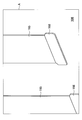
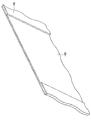
- FIG. 9A is an explanatory view showing a rear cover 106 provided with a recess 165 having a depression in a perspective view from the front side in the liquid crystal display device 100 according to the present embodiment.
- FIG. 9B is an explanatory diagram showing, in an enlarged manner, the rear cover 106 provided with a recess 165 having a recess in the liquid crystal display device 100 according to the present embodiment.
- FIG. 9B is an enlarged view of the portion indicated by the symbol A in FIG. 9A.
- FIG. 9C is an explanatory diagram showing a cross-sectional shape of the rear cover 106 provided with a recess 165 having a recess in the liquid crystal display device 100 according to the present embodiment.
- a recess 165 having a recess is provided in the rear cover 106, and a flexible substrate 156 connecting the panel control board 151 and the panel driver board 122 mounted on the chassis 108 is passed through the recess 165.
- a flexible substrate 156 connecting the panel control board 151 and the panel driver board 122 mounted on the chassis 108 is passed through the recess 165.
- the flexible substrate 156 can be passed through the recess on the back side of the reflector 115, and the light guide plate 114 and the reflector in the portion through which the flexible substrate 156 passes.
- the thickness of 115 is not affected. Therefore, the optical influence in the portion where the flexible substrate 156 passes can be prevented with respect to the light emitted from the light source 112.
- the rear cover 106 may be provided with a hole 166 for allowing the flexible substrate 156 to pass therethrough.
- 9A and 9B show a hole 166 for passing the flexible substrate 156 from the back side under the recess 165. Needless to say, the shape of the hole through which the flexible substrate 156 passes is not limited to that shown in FIGS. 9A and 9B.
- the shape of the rear cover 106 in the liquid crystal display device 100 according to the embodiment of the present invention has been described above. Next, the shape of the peripheral portion of the front bezel 104 in the liquid crystal display device 100 according to the embodiment of the present invention will be described. .
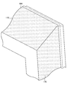
- FIG. 10A is an explanatory view showing the shape of the peripheral edge of the front bezel 104 in the liquid crystal display device 100 according to the embodiment of the present invention in a perspective view.
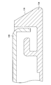
- 10B and 10C are explanatory views showing the cross-sectional shapes of the front bezel 104 and the rear cover 106 in the liquid crystal display device 100 according to the embodiment of the present invention.
- a tapered portion 170 is formed on the peripheral portion on the back side of the front bezel 104 in the liquid crystal display device 100 according to the embodiment of the present invention.
- the tapered portion 170 has a predetermined inclination so that the back side becomes smaller from the front side to the back side.
- the front bezel 104 is formed with a tapered portion 170 having a predetermined inclination so that the back side becomes smaller from the front side to the back side.
- the front bezel 104 and the rear cover 106 may have a structure in which a spacer 172 is sandwiched therebetween and locked with a screw 171.
- the structure for locking the front bezel 104 and the rear cover 106 is not limited to this example, and the material of the spacer 172 is not limited to a predetermined material.
- the inclination of the tapered portion 170 is not limited to that shown in FIGS. 10A to 10C.
- An appropriate inclination can be determined from the relationship between the visual effect described above and the strength of the front bezel 104.
- FIG. 11 is an explanatory diagram showing a state before the chassis 108 and the stand 110 are connected, as viewed from the back side of the liquid crystal display device 100 in the liquid crystal display device 100 according to the embodiment of the present invention.
- FIG. 12 is an explanatory diagram showing a perspective view of the liquid crystal display device 100 according to the embodiment of the present invention when the state after the chassis 108 and the stand 110 are connected is viewed from the back side of the liquid crystal display device 100. It is.
- the chassis 108 is provided with a connector 181 and the stand 110 is provided with a connector 182.
- the chassis 108 and the stand 110 are connected.
- the chassis 108 and the stand 110 When the chassis 108 and the stand 110 are connected, the chassis 108 and the stand 110 are also electrically connected by the connectors 181 and 182. By electrically connecting the chassis 108 and the stand 110 with the connectors 181 and 182, sound can be output from a speaker (not shown) built in the stand 110.
- the stand 110 may be provided with a cover.
- the cover 183 may be provided on the arm portion 184 of the stand 110 so as to be opened and closed. By providing the cover 183 so that it can be opened and closed, a power cable and other cables can be accommodated in the arm portion 184.
- connection structure between the chassis 108 and the stand 110 in the liquid crystal display device 100 according to the embodiment of the present invention has been described above.
- the heat generated from the light source 112 is formed of a metal having high thermal conductivity and excellent moldability, for example, aluminum. Absorbed by the heat sink 130 formed. The heat absorbed by the heat sink 130 is transmitted to the rear cover 106 formed of a metal having high thermal conductivity and excellent moldability, for example, aluminum, and is released from the rear cover 106.
- the heat generated from the light source 112 can be efficiently discharged from the liquid crystal display device 100 without providing a heat dissipation mechanism such as a fan or a fin.
- the heat absorbed by the heat sink 130 can also be released from the front bezel 104, but the middle chassis is between the heat sink 130 and the front bezel 104.
- the middle chassis 131 may be formed of a material having a lower thermal conductivity than the heat sink 130, such as a synthetic resin.
- the middle chassis 131 by forming the middle chassis 131 with a material having a lower thermal conductivity than the heat sink 130, the heat transmitted to the front bezel 104 is less than the heat transmitted to the rear cover 106. Therefore, the heat discharged from the front bezel 104 is less than the heat discharged from the rear cover 106, and a significant temperature increase on the front side of the liquid crystal display device 100 can be suppressed.
- a liquid crystal display device using liquid crystal is illustrated as an example of the display device, but the present invention is not limited to such an example.
- the present invention can be applied to a display device in which a heat source is provided along each side of the display panel.
- the present invention is applicable to display devices.
Landscapes
- Physics & Mathematics (AREA)
- Nonlinear Science (AREA)
- Optics & Photonics (AREA)
- General Physics & Mathematics (AREA)
- Crystallography & Structural Chemistry (AREA)
- Chemical & Material Sciences (AREA)
- Mathematical Physics (AREA)
- Engineering & Computer Science (AREA)
- Liquid Crystal (AREA)
- Thermal Sciences (AREA)
- Microelectronics & Electronic Packaging (AREA)
- Multimedia (AREA)
- Signal Processing (AREA)
- Devices For Indicating Variable Information By Combining Individual Elements (AREA)
Abstract
Description
102 表示パネル
104 フロントベゼル
106 リアカバー
108 シャーシ
110 スタンド
112 光源
114 導光板
115 反射板
117 光学シート
121 液晶セル
122 パネルドライバ基板
123 LED
124 LED回路基板
130 ヒートシンク
131 ミドルシャーシ
151 パネル制御基板
153 信号基板
154 電源基板
155 LEDドライバ基板
156 フレキシブル基板
161 偏光板
162 ガラス基板
163 ガラス基板
164 偏光板
165 凹部
170 テーパー部
171 ネジ
172 スペーサ
181、182 コネクタ
183 カバー
184 アーム部
〔1〕本発明の一実施形態にかかる液晶表示装置の説明
〔2〕本発明の一実施形態にかかる液晶表示装置における放熱機構の説明
〔3〕本発明の一実施形態にかかる液晶表示装置の構造の説明
〔4〕まとめ
まず、本発明の一実施形態にかかる液晶表示装置の外観について説明する。図1は、本発明の一実施形態にかかる液晶表示装置100を正面から示す説明図であり、図2は、本発明の一実施形態にかかる液晶表示装置100を側面から示す説明図である。以下、図1および図2を用いて、本発明の一実施形態にかかる液晶表示装置100の外観について説明する。
本実施形態においては、光源112として白色光を発光するLEDを用いることができる。図5に示した光源112においては、画面のサイズが大きくなればなるほど、すなわち表示パネル102の大きさが大きくなればなるほど、表示パネル102全体に光を照射するために、光源112一列あたりのLED123の数も増やす必要がある。従って、画面のサイズが大きくなればなるほど、LED123から発生する熱も多くなる。よって、光源112は本発明の熱源の一例である。
次に、本発明の一実施形態にかかる液晶表示装置100におけるリアカバー106の形状について説明する。
以上説明したように、本発明の一実施形態にかかる液晶表示装置100によれば、光源112から発生する熱を、熱伝導率が高く成形性に優れた金属、例えばアルミニウムで形成されたヒートシンク130で吸収する。そして、ヒートシンク130で吸収した熱を、熱伝導率が高く成形性に優れた金属、例えばアルミニウムで形成されたリアカバー106へ伝達し、リアカバー106から放出する。このように、光源112から発生した熱を伝達させることで、ファンやフィン等の放熱機構を設けること無く、光源112から発生した熱を効率よく液晶表示装置100から排出させることができる。
Claims (6)
- 画像を表示する表示パネルと、
前記表示パネルの少なくとも一辺の側面側に設けられる熱源と、
前記熱源で発生する熱を吸熱する吸熱部と、
前記表示パネルの背面側に設けられ、金属からなり、一部が前記吸熱部に密着する背面板と、
前記表示パネルの前面側に設けられ、金属からなる前面板と、
前記前面板と前記吸熱部との間に設けられるミドルシャーシと、
を備える、表示装置。 - 前記ミドルシャーシは、前記吸熱部の熱伝導率より低い熱伝導率を有する材料からなる、請求項1に記載の表示装置。
- 前記表示パネルの駆動を制御するパネル制御基板をさらに備え、
前記パネル制御基板は前記背面板の背面中央部分に位置する、請求項1に記載の表示装置。 - 前記表示パネルの画像の表示を制御するパネルドライバ基板と、
前記パネル制御基板と前記パネルドライバ基板との間を接続するフレキシブル基板と、
をさらに備え、
前記背面板は、前記フレキシブル基板の幅、長さ及び厚さに相当する窪みを有し、前記フレキシブル基板を通す凹部を備える、請求項3に記載の表示装置。 - 前記前面板の周縁部は、前記前面側から前記背面側にかけて前記背面側が小さくなるようなテーパー部を有している、請求項1に記載の表示装置。
- 前記熱源は可視光を発光し、
前記熱源から発せられる光を拡散し前記表示パネルに照射して前記表示パネルに画像を表示させる光照射部をさらに備える、請求項1に記載の表示装置。
Priority Applications (9)
| Application Number | Priority Date | Filing Date | Title |
|---|---|---|---|
| CN200980131501.0A CN102124396B (zh) | 2008-08-27 | 2009-08-26 | 显示设备 |
| RU2011105159/28A RU2468402C2 (ru) | 2008-08-27 | 2009-08-26 | Устройство отображения |
| KR1020117002926A KR101681790B1 (ko) | 2008-08-27 | 2009-08-26 | 표시 장치 |
| US13/059,067 US8811017B2 (en) | 2008-08-27 | 2009-08-26 | Display apparatus |
| BRPI0917636-5A BRPI0917636B1 (pt) | 2008-08-27 | 2009-08-26 | Dispositivo de exibição |
| KR1020167032827A KR101904633B1 (ko) | 2008-08-27 | 2009-08-26 | 표시 장치 |
| US14/447,263 US9395572B2 (en) | 2008-08-27 | 2014-07-30 | Display apparatus |
| US15/181,808 US10175520B2 (en) | 2008-08-27 | 2016-06-14 | Display apparatus |
| US16/142,410 US12422709B2 (en) | 2008-08-27 | 2018-09-26 | Display apparatus |
Applications Claiming Priority (2)
| Application Number | Priority Date | Filing Date | Title |
|---|---|---|---|
| JP2008218501A JP2010054718A (ja) | 2008-08-27 | 2008-08-27 | 表示装置 |
| JP2008-218501 | 2008-08-27 |
Related Child Applications (2)
| Application Number | Title | Priority Date | Filing Date |
|---|---|---|---|
| US13/059,067 A-371-Of-International US8811017B2 (en) | 2008-08-27 | 2009-08-26 | Display apparatus |
| US14/447,263 Continuation US9395572B2 (en) | 2008-08-27 | 2014-07-30 | Display apparatus |
Publications (1)
| Publication Number | Publication Date |
|---|---|
| WO2010024299A1 true WO2010024299A1 (ja) | 2010-03-04 |
Family
ID=41721466
Family Applications (1)
| Application Number | Title | Priority Date | Filing Date |
|---|---|---|---|
| PCT/JP2009/064883 Ceased WO2010024299A1 (ja) | 2008-08-27 | 2009-08-26 | 表示装置 |
Country Status (7)
| Country | Link |
|---|---|
| US (4) | US8811017B2 (ja) |
| JP (1) | JP2010054718A (ja) |
| KR (2) | KR101904633B1 (ja) |
| CN (2) | CN103913878B (ja) |
| BR (1) | BRPI0917636B1 (ja) |
| RU (1) | RU2468402C2 (ja) |
| WO (1) | WO2010024299A1 (ja) |
Cited By (3)
| Publication number | Priority date | Publication date | Assignee | Title |
|---|---|---|---|---|
| US20130107161A1 (en) * | 2011-10-26 | 2013-05-02 | Samsung Electronics Co., Ltd. | Liquid crystal display |
| RU2510100C2 (ru) * | 2010-06-23 | 2014-03-20 | Сони Корпорейшн | Твердотельное устройство формирования изображений и электронное устройство |
| US10775552B2 (en) | 2016-02-09 | 2020-09-15 | Sony Corporation | Display device |
Families Citing this family (454)
| Publication number | Priority date | Publication date | Assignee | Title |
|---|---|---|---|---|
| US9060770B2 (en) | 2003-05-20 | 2015-06-23 | Ethicon Endo-Surgery, Inc. | Robotically-driven surgical instrument with E-beam driver |
| US20070084897A1 (en) | 2003-05-20 | 2007-04-19 | Shelton Frederick E Iv | Articulating surgical stapling instrument incorporating a two-piece e-beam firing mechanism |
| US11890012B2 (en) | 2004-07-28 | 2024-02-06 | Cilag Gmbh International | Staple cartridge comprising cartridge body and attached support |
| US8215531B2 (en) | 2004-07-28 | 2012-07-10 | Ethicon Endo-Surgery, Inc. | Surgical stapling instrument having a medical substance dispenser |
| US9072535B2 (en) | 2011-05-27 | 2015-07-07 | Ethicon Endo-Surgery, Inc. | Surgical stapling instruments with rotatable staple deployment arrangements |
| US11998198B2 (en) | 2004-07-28 | 2024-06-04 | Cilag Gmbh International | Surgical stapling instrument incorporating a two-piece E-beam firing mechanism |
| US11246590B2 (en) | 2005-08-31 | 2022-02-15 | Cilag Gmbh International | Staple cartridge including staple drivers having different unfired heights |
| US7669746B2 (en) | 2005-08-31 | 2010-03-02 | Ethicon Endo-Surgery, Inc. | Staple cartridges for forming staples having differing formed staple heights |
| US9237891B2 (en) | 2005-08-31 | 2016-01-19 | Ethicon Endo-Surgery, Inc. | Robotically-controlled surgical stapling devices that produce formed staples having different lengths |
| US11484312B2 (en) | 2005-08-31 | 2022-11-01 | Cilag Gmbh International | Staple cartridge comprising a staple driver arrangement |
| US7934630B2 (en) | 2005-08-31 | 2011-05-03 | Ethicon Endo-Surgery, Inc. | Staple cartridges for forming staples having differing formed staple heights |
| US10159482B2 (en) | 2005-08-31 | 2018-12-25 | Ethicon Llc | Fastener cartridge assembly comprising a fixed anvil and different staple heights |
| US20070106317A1 (en) | 2005-11-09 | 2007-05-10 | Shelton Frederick E Iv | Hydraulically and electrically actuated articulation joints for surgical instruments |
| US7845537B2 (en) | 2006-01-31 | 2010-12-07 | Ethicon Endo-Surgery, Inc. | Surgical instrument having recording capabilities |
| US11793518B2 (en) | 2006-01-31 | 2023-10-24 | Cilag Gmbh International | Powered surgical instruments with firing system lockout arrangements |
| US8186555B2 (en) | 2006-01-31 | 2012-05-29 | Ethicon Endo-Surgery, Inc. | Motor-driven surgical cutting and fastening instrument with mechanical closure system |
| US7753904B2 (en) | 2006-01-31 | 2010-07-13 | Ethicon Endo-Surgery, Inc. | Endoscopic surgical instrument with a handle that can articulate with respect to the shaft |
| US11278279B2 (en) | 2006-01-31 | 2022-03-22 | Cilag Gmbh International | Surgical instrument assembly |
| US20110024477A1 (en) | 2009-02-06 | 2011-02-03 | Hall Steven G | Driven Surgical Stapler Improvements |
| US20120292367A1 (en) | 2006-01-31 | 2012-11-22 | Ethicon Endo-Surgery, Inc. | Robotically-controlled end effector |
| US8820603B2 (en) | 2006-01-31 | 2014-09-02 | Ethicon Endo-Surgery, Inc. | Accessing data stored in a memory of a surgical instrument |
| US11224427B2 (en) | 2006-01-31 | 2022-01-18 | Cilag Gmbh International | Surgical stapling system including a console and retraction assembly |
| US20110290856A1 (en) | 2006-01-31 | 2011-12-01 | Ethicon Endo-Surgery, Inc. | Robotically-controlled surgical instrument with force-feedback capabilities |
| US8708213B2 (en) | 2006-01-31 | 2014-04-29 | Ethicon Endo-Surgery, Inc. | Surgical instrument having a feedback system |
| US8992422B2 (en) | 2006-03-23 | 2015-03-31 | Ethicon Endo-Surgery, Inc. | Robotically-controlled endoscopic accessory channel |
| US8322455B2 (en) | 2006-06-27 | 2012-12-04 | Ethicon Endo-Surgery, Inc. | Manually driven surgical cutting and fastening instrument |
| US8485412B2 (en) | 2006-09-29 | 2013-07-16 | Ethicon Endo-Surgery, Inc. | Surgical staples having attached drivers and stapling instruments for deploying the same |
| US10568652B2 (en) | 2006-09-29 | 2020-02-25 | Ethicon Llc | Surgical staples having attached drivers of different heights and stapling instruments for deploying the same |
| US11980366B2 (en) | 2006-10-03 | 2024-05-14 | Cilag Gmbh International | Surgical instrument |
| US8632535B2 (en) | 2007-01-10 | 2014-01-21 | Ethicon Endo-Surgery, Inc. | Interlock and surgical instrument including same |
| US11291441B2 (en) | 2007-01-10 | 2022-04-05 | Cilag Gmbh International | Surgical instrument with wireless communication between control unit and remote sensor |
| US8652120B2 (en) | 2007-01-10 | 2014-02-18 | Ethicon Endo-Surgery, Inc. | Surgical instrument with wireless communication between control unit and sensor transponders |
| US8684253B2 (en) | 2007-01-10 | 2014-04-01 | Ethicon Endo-Surgery, Inc. | Surgical instrument with wireless communication between a control unit of a robotic system and remote sensor |
| US20080169332A1 (en) | 2007-01-11 | 2008-07-17 | Shelton Frederick E | Surgical stapling device with a curved cutting member |
| US11039836B2 (en) | 2007-01-11 | 2021-06-22 | Cilag Gmbh International | Staple cartridge for use with a surgical stapling instrument |
| US8727197B2 (en) | 2007-03-15 | 2014-05-20 | Ethicon Endo-Surgery, Inc. | Staple cartridge cavity configuration with cooperative surgical staple |
| US8893946B2 (en) | 2007-03-28 | 2014-11-25 | Ethicon Endo-Surgery, Inc. | Laparoscopic tissue thickness and clamp load measuring devices |
| US11857181B2 (en) | 2007-06-04 | 2024-01-02 | Cilag Gmbh International | Robotically-controlled shaft based rotary drive systems for surgical instruments |
| US8931682B2 (en) | 2007-06-04 | 2015-01-13 | Ethicon Endo-Surgery, Inc. | Robotically-controlled shaft based rotary drive systems for surgical instruments |
| US7753245B2 (en) | 2007-06-22 | 2010-07-13 | Ethicon Endo-Surgery, Inc. | Surgical stapling instruments |
| US11849941B2 (en) | 2007-06-29 | 2023-12-26 | Cilag Gmbh International | Staple cartridge having staple cavities extending at a transverse angle relative to a longitudinal cartridge axis |
| US7866527B2 (en) | 2008-02-14 | 2011-01-11 | Ethicon Endo-Surgery, Inc. | Surgical stapling apparatus with interlockable firing system |
| US11986183B2 (en) | 2008-02-14 | 2024-05-21 | Cilag Gmbh International | Surgical cutting and fastening instrument comprising a plurality of sensors to measure an electrical parameter |
| US8573465B2 (en) | 2008-02-14 | 2013-11-05 | Ethicon Endo-Surgery, Inc. | Robotically-controlled surgical end effector system with rotary actuated closure systems |
| US9179912B2 (en) | 2008-02-14 | 2015-11-10 | Ethicon Endo-Surgery, Inc. | Robotically-controlled motorized surgical cutting and fastening instrument |
| US8758391B2 (en) | 2008-02-14 | 2014-06-24 | Ethicon Endo-Surgery, Inc. | Interchangeable tools for surgical instruments |
| RU2493788C2 (ru) | 2008-02-14 | 2013-09-27 | Этикон Эндо-Серджери, Инк. | Хирургический режущий и крепежный инструмент, имеющий радиочастотные электроды |
| US7819298B2 (en) | 2008-02-14 | 2010-10-26 | Ethicon Endo-Surgery, Inc. | Surgical stapling apparatus with control features operable with one hand |
| US8636736B2 (en) | 2008-02-14 | 2014-01-28 | Ethicon Endo-Surgery, Inc. | Motorized surgical cutting and fastening instrument |
| US20130153641A1 (en) | 2008-02-15 | 2013-06-20 | Ethicon Endo-Surgery, Inc. | Releasable layer of material and surgical end effector having the same |
| US11272927B2 (en) | 2008-02-15 | 2022-03-15 | Cilag Gmbh International | Layer arrangements for surgical staple cartridges |
| US8210411B2 (en) | 2008-09-23 | 2012-07-03 | Ethicon Endo-Surgery, Inc. | Motor-driven surgical cutting instrument |
| US11648005B2 (en) | 2008-09-23 | 2023-05-16 | Cilag Gmbh International | Robotically-controlled motorized surgical instrument with an end effector |
| US9005230B2 (en) | 2008-09-23 | 2015-04-14 | Ethicon Endo-Surgery, Inc. | Motorized surgical instrument |
| US9386983B2 (en) | 2008-09-23 | 2016-07-12 | Ethicon Endo-Surgery, Llc | Robotically-controlled motorized surgical instrument |
| US8608045B2 (en) | 2008-10-10 | 2013-12-17 | Ethicon Endo-Sugery, Inc. | Powered surgical cutting and stapling apparatus with manually retractable firing system |
| US8517239B2 (en) | 2009-02-05 | 2013-08-27 | Ethicon Endo-Surgery, Inc. | Surgical stapling instrument comprising a magnetic element driver |
| JP2012517287A (ja) | 2009-02-06 | 2012-08-02 | エシコン・エンド−サージェリィ・インコーポレイテッド | 被駆動式手術用ステープラの改良 |
| US8444036B2 (en) | 2009-02-06 | 2013-05-21 | Ethicon Endo-Surgery, Inc. | Motor driven surgical fastener device with mechanisms for adjusting a tissue gap within the end effector |
| US8851354B2 (en) | 2009-12-24 | 2014-10-07 | Ethicon Endo-Surgery, Inc. | Surgical cutting instrument that analyzes tissue thickness |
| US8220688B2 (en) | 2009-12-24 | 2012-07-17 | Ethicon Endo-Surgery, Inc. | Motor-driven surgical cutting instrument with electric actuator directional control assembly |
| JP2012014947A (ja) * | 2010-06-30 | 2012-01-19 | Sharp Corp | 照明装置及びそれを備えた画像表示装置 |
| US8783543B2 (en) | 2010-07-30 | 2014-07-22 | Ethicon Endo-Surgery, Inc. | Tissue acquisition arrangements and methods for surgical stapling devices |
| US9113865B2 (en) | 2010-09-30 | 2015-08-25 | Ethicon Endo-Surgery, Inc. | Staple cartridge comprising a layer |
| US11298125B2 (en) | 2010-09-30 | 2022-04-12 | Cilag Gmbh International | Tissue stapler having a thickness compensator |
| US10405854B2 (en) | 2010-09-30 | 2019-09-10 | Ethicon Llc | Surgical stapling cartridge with layer retention features |
| US11925354B2 (en) | 2010-09-30 | 2024-03-12 | Cilag Gmbh International | Staple cartridge comprising staples positioned within a compressible portion thereof |
| US10945731B2 (en) | 2010-09-30 | 2021-03-16 | Ethicon Llc | Tissue thickness compensator comprising controlled release and expansion |
| US12213666B2 (en) | 2010-09-30 | 2025-02-04 | Cilag Gmbh International | Tissue thickness compensator comprising layers |
| US9241714B2 (en) | 2011-04-29 | 2016-01-26 | Ethicon Endo-Surgery, Inc. | Tissue thickness compensator and method for making the same |
| US9232941B2 (en) | 2010-09-30 | 2016-01-12 | Ethicon Endo-Surgery, Inc. | Tissue thickness compensator comprising a reservoir |
| US9629814B2 (en) | 2010-09-30 | 2017-04-25 | Ethicon Endo-Surgery, Llc | Tissue thickness compensator configured to redistribute compressive forces |
| US11812965B2 (en) | 2010-09-30 | 2023-11-14 | Cilag Gmbh International | Layer of material for a surgical end effector |
| US9364233B2 (en) | 2010-09-30 | 2016-06-14 | Ethicon Endo-Surgery, Llc | Tissue thickness compensators for circular surgical staplers |
| US9320523B2 (en) | 2012-03-28 | 2016-04-26 | Ethicon Endo-Surgery, Llc | Tissue thickness compensator comprising tissue ingrowth features |
| US8695866B2 (en) | 2010-10-01 | 2014-04-15 | Ethicon Endo-Surgery, Inc. | Surgical instrument having a power control circuit |
| JP5611018B2 (ja) * | 2010-12-10 | 2014-10-22 | シャープ株式会社 | 表示装置 |
| JP5032651B2 (ja) | 2010-12-27 | 2012-09-26 | 株式会社東芝 | テレビジョン受像機、及び電子機器 |
| JP5159872B2 (ja) | 2010-12-27 | 2013-03-13 | 株式会社東芝 | テレビジョン受像機 |
| JP5845795B2 (ja) * | 2011-10-12 | 2016-01-20 | 船井電機株式会社 | 表示装置 |
| JP2012208254A (ja) * | 2011-03-29 | 2012-10-25 | Funai Electric Co Ltd | 表示装置用照明装置および表示装置 |
| BR112013027794B1 (pt) | 2011-04-29 | 2020-12-15 | Ethicon Endo-Surgery, Inc | Conjunto de cartucho de grampos |
| JP5892736B2 (ja) | 2011-05-24 | 2016-03-23 | ソニー株式会社 | 表示装置 |
| US11207064B2 (en) | 2011-05-27 | 2021-12-28 | Cilag Gmbh International | Automated end effector component reloading system for use with a robotic system |
| JP2012253094A (ja) | 2011-05-31 | 2012-12-20 | Sony Corp | 電子機器 |
| US9621838B2 (en) | 2011-10-25 | 2017-04-11 | Funai Electric Co., Ltd. | Display device and television apparatus |
| KR20130090713A (ko) * | 2012-02-06 | 2013-08-14 | 삼성전자주식회사 | 디스플레이 장치 및 그 제조방법 |
| US9044230B2 (en) | 2012-02-13 | 2015-06-02 | Ethicon Endo-Surgery, Inc. | Surgical cutting and fastening instrument with apparatus for determining cartridge and firing motion status |
| US9322976B2 (en) * | 2012-02-17 | 2016-04-26 | Sharp Kabushiki Kaisha | Lighting device, display device and television device |
| MX358135B (es) | 2012-03-28 | 2018-08-06 | Ethicon Endo Surgery Inc | Compensador de grosor de tejido que comprende una pluralidad de capas. |
| CN104379068B (zh) | 2012-03-28 | 2017-09-22 | 伊西康内外科公司 | 包括组织厚度补偿件的保持器组件 |
| MX350846B (es) | 2012-03-28 | 2017-09-22 | Ethicon Endo Surgery Inc | Compensador de grosor de tejido que comprende cápsulas que definen un ambiente de baja presión. |
| US9101358B2 (en) | 2012-06-15 | 2015-08-11 | Ethicon Endo-Surgery, Inc. | Articulatable surgical instrument comprising a firing drive |
| US11197671B2 (en) | 2012-06-28 | 2021-12-14 | Cilag Gmbh International | Stapling assembly comprising a lockout |
| US9204879B2 (en) | 2012-06-28 | 2015-12-08 | Ethicon Endo-Surgery, Inc. | Flexible drive member |
| US20140001231A1 (en) | 2012-06-28 | 2014-01-02 | Ethicon Endo-Surgery, Inc. | Firing system lockout arrangements for surgical instruments |
| US9282974B2 (en) | 2012-06-28 | 2016-03-15 | Ethicon Endo-Surgery, Llc | Empty clip cartridge lockout |
| US12383267B2 (en) | 2012-06-28 | 2025-08-12 | Cilag Gmbh International | Robotically powered surgical device with manually-actuatable reversing system |
| US9226751B2 (en) | 2012-06-28 | 2016-01-05 | Ethicon Endo-Surgery, Inc. | Surgical instrument system including replaceable end effectors |
| JP6290201B2 (ja) | 2012-06-28 | 2018-03-07 | エシコン・エンド−サージェリィ・インコーポレイテッドEthicon Endo−Surgery,Inc. | 空クリップカートリッジ用のロックアウト |
| US9289256B2 (en) | 2012-06-28 | 2016-03-22 | Ethicon Endo-Surgery, Llc | Surgical end effectors having angled tissue-contacting surfaces |
| BR112014032776B1 (pt) | 2012-06-28 | 2021-09-08 | Ethicon Endo-Surgery, Inc | Sistema de instrumento cirúrgico e kit cirúrgico para uso com um sistema de instrumento cirúrgico |
| EP2701475A1 (de) * | 2012-08-22 | 2014-02-26 | Ruf Telematik AG | Gehäuse zur Aufnahme eines Flachbildschirms |
| JP2013061673A (ja) * | 2012-12-05 | 2013-04-04 | Toshiba Corp | テレビジョン受像機 |
| MX368026B (es) | 2013-03-01 | 2019-09-12 | Ethicon Endo Surgery Inc | Instrumento quirúrgico articulable con vías conductoras para la comunicación de la señal. |
| RU2669463C2 (ru) | 2013-03-01 | 2018-10-11 | Этикон Эндо-Серджери, Инк. | Хирургический инструмент с мягким упором |
| US9351726B2 (en) | 2013-03-14 | 2016-05-31 | Ethicon Endo-Surgery, Llc | Articulation control system for articulatable surgical instruments |
| US9629629B2 (en) | 2013-03-14 | 2017-04-25 | Ethicon Endo-Surgey, LLC | Control systems for surgical instruments |
| US9801626B2 (en) | 2013-04-16 | 2017-10-31 | Ethicon Llc | Modular motor driven surgical instruments with alignment features for aligning rotary drive shafts with surgical end effector shafts |
| BR112015026109B1 (pt) | 2013-04-16 | 2022-02-22 | Ethicon Endo-Surgery, Inc | Instrumento cirúrgico |
| US20150053737A1 (en) | 2013-08-23 | 2015-02-26 | Ethicon Endo-Surgery, Inc. | End effector detection systems for surgical instruments |
| MX369362B (es) | 2013-08-23 | 2019-11-06 | Ethicon Endo Surgery Llc | Dispositivos de retraccion de miembros de disparo para instrumentos quirurgicos electricos. |
| US9962161B2 (en) | 2014-02-12 | 2018-05-08 | Ethicon Llc | Deliverable surgical instrument |
| US20160198071A1 (en) * | 2014-02-21 | 2016-07-07 | Microsoft Technology Licensing, Llc | Compliant support for component alignment |
| BR112016019387B1 (pt) | 2014-02-24 | 2022-11-29 | Ethicon Endo-Surgery, Llc | Sistema de instrumento cirúrgico e cartucho de prendedores para uso com um instrumento cirúrgico de fixação |
| BR112016021943B1 (pt) | 2014-03-26 | 2022-06-14 | Ethicon Endo-Surgery, Llc | Instrumento cirúrgico para uso por um operador em um procedimento cirúrgico |
| US10013049B2 (en) | 2014-03-26 | 2018-07-03 | Ethicon Llc | Power management through sleep options of segmented circuit and wake up control |
| US12232723B2 (en) | 2014-03-26 | 2025-02-25 | Cilag Gmbh International | Systems and methods for controlling a segmented circuit |
| US9750499B2 (en) | 2014-03-26 | 2017-09-05 | Ethicon Llc | Surgical stapling instrument system |
| US20150272557A1 (en) | 2014-03-26 | 2015-10-01 | Ethicon Endo-Surgery, Inc. | Modular surgical instrument system |
| US10561422B2 (en) | 2014-04-16 | 2020-02-18 | Ethicon Llc | Fastener cartridge comprising deployable tissue engaging members |
| US10327764B2 (en) | 2014-09-26 | 2019-06-25 | Ethicon Llc | Method for creating a flexible staple line |
| US20150297223A1 (en) | 2014-04-16 | 2015-10-22 | Ethicon Endo-Surgery, Inc. | Fastener cartridges including extensions having different configurations |
| JP6532889B2 (ja) | 2014-04-16 | 2019-06-19 | エシコン エルエルシーEthicon LLC | 締結具カートリッジ組立体及びステープル保持具カバー配置構成 |
| CN106456176B (zh) | 2014-04-16 | 2019-06-28 | 伊西康内外科有限责任公司 | 包括具有不同构型的延伸部的紧固件仓 |
| CN106456158B (zh) | 2014-04-16 | 2019-02-05 | 伊西康内外科有限责任公司 | 包括非一致紧固件的紧固件仓 |
| USD744892S1 (en) * | 2014-05-26 | 2015-12-08 | Filip Technologies, Inc. | Band extension |
| AU2015277337B2 (en) * | 2014-06-16 | 2018-05-31 | Manufacturing Resources International, Inc. | Transparent LCD assembly with display case |
| BR112017004361B1 (pt) | 2014-09-05 | 2023-04-11 | Ethicon Llc | Sistema eletrônico para um instrumento cirúrgico |
| US9724094B2 (en) | 2014-09-05 | 2017-08-08 | Ethicon Llc | Adjunct with integrated sensors to quantify tissue compression |
| US11311294B2 (en) | 2014-09-05 | 2022-04-26 | Cilag Gmbh International | Powered medical device including measurement of closure state of jaws |
| US10105142B2 (en) | 2014-09-18 | 2018-10-23 | Ethicon Llc | Surgical stapler with plurality of cutting elements |
| US11523821B2 (en) | 2014-09-26 | 2022-12-13 | Cilag Gmbh International | Method for creating a flexible staple line |
| JP6648119B2 (ja) | 2014-09-26 | 2020-02-14 | エシコン エルエルシーEthicon LLC | 外科ステープル留めバットレス及び付属物材料 |
| US10649273B2 (en) | 2014-10-08 | 2020-05-12 | Manufacturing Resources International, Inc. | LED assembly for transparent liquid crystal display and static graphic |
| US10076325B2 (en) | 2014-10-13 | 2018-09-18 | Ethicon Llc | Surgical stapling apparatus comprising a tissue stop |
| KR102233127B1 (ko) * | 2014-10-14 | 2021-03-26 | 엘지디스플레이 주식회사 | 가이드 패널 및 이를 포함한 액정 표시 장치 |
| US9924944B2 (en) | 2014-10-16 | 2018-03-27 | Ethicon Llc | Staple cartridge comprising an adjunct material |
| US10517594B2 (en) | 2014-10-29 | 2019-12-31 | Ethicon Llc | Cartridge assemblies for surgical staplers |
| US11141153B2 (en) | 2014-10-29 | 2021-10-12 | Cilag Gmbh International | Staple cartridges comprising driver arrangements |
| US9844376B2 (en) | 2014-11-06 | 2017-12-19 | Ethicon Llc | Staple cartridge comprising a releasable adjunct material |
| US10736636B2 (en) | 2014-12-10 | 2020-08-11 | Ethicon Llc | Articulatable surgical instrument system |
| US9987000B2 (en) | 2014-12-18 | 2018-06-05 | Ethicon Llc | Surgical instrument assembly comprising a flexible articulation system |
| US9844375B2 (en) | 2014-12-18 | 2017-12-19 | Ethicon Llc | Drive arrangements for articulatable surgical instruments |
| US10085748B2 (en) | 2014-12-18 | 2018-10-02 | Ethicon Llc | Locking arrangements for detachable shaft assemblies with articulatable surgical end effectors |
| US10188385B2 (en) | 2014-12-18 | 2019-01-29 | Ethicon Llc | Surgical instrument system comprising lockable systems |
| US10245027B2 (en) | 2014-12-18 | 2019-04-02 | Ethicon Llc | Surgical instrument with an anvil that is selectively movable about a discrete non-movable axis relative to a staple cartridge |
| RU2703684C2 (ru) | 2014-12-18 | 2019-10-21 | ЭТИКОН ЭНДО-СЕРДЖЕРИ, ЭлЭлСи | Хирургический инструмент с упором, который выполнен с возможностью избирательного перемещения относительно кассеты со скобами вокруг дискретной неподвижной оси |
| US9844374B2 (en) | 2014-12-18 | 2017-12-19 | Ethicon Llc | Surgical instrument systems comprising an articulatable end effector and means for adjusting the firing stroke of a firing member |
| US10180463B2 (en) | 2015-02-27 | 2019-01-15 | Ethicon Llc | Surgical apparatus configured to assess whether a performance parameter of the surgical apparatus is within an acceptable performance band |
| US10159483B2 (en) | 2015-02-27 | 2018-12-25 | Ethicon Llc | Surgical apparatus configured to track an end-of-life parameter |
| US11154301B2 (en) | 2015-02-27 | 2021-10-26 | Cilag Gmbh International | Modular stapling assembly |
| US10617412B2 (en) | 2015-03-06 | 2020-04-14 | Ethicon Llc | System for detecting the mis-insertion of a staple cartridge into a surgical stapler |
| US10245033B2 (en) | 2015-03-06 | 2019-04-02 | Ethicon Llc | Surgical instrument comprising a lockable battery housing |
| US10548504B2 (en) | 2015-03-06 | 2020-02-04 | Ethicon Llc | Overlaid multi sensor radio frequency (RF) electrode system to measure tissue compression |
| US9808246B2 (en) | 2015-03-06 | 2017-11-07 | Ethicon Endo-Surgery, Llc | Method of operating a powered surgical instrument |
| US9924961B2 (en) | 2015-03-06 | 2018-03-27 | Ethicon Endo-Surgery, Llc | Interactive feedback system for powered surgical instruments |
| US9993248B2 (en) | 2015-03-06 | 2018-06-12 | Ethicon Endo-Surgery, Llc | Smart sensors with local signal processing |
| US10687806B2 (en) | 2015-03-06 | 2020-06-23 | Ethicon Llc | Adaptive tissue compression techniques to adjust closure rates for multiple tissue types |
| US10441279B2 (en) | 2015-03-06 | 2019-10-15 | Ethicon Llc | Multiple level thresholds to modify operation of powered surgical instruments |
| US9901342B2 (en) | 2015-03-06 | 2018-02-27 | Ethicon Endo-Surgery, Llc | Signal and power communication system positioned on a rotatable shaft |
| JP2020121162A (ja) | 2015-03-06 | 2020-08-13 | エシコン エルエルシーEthicon LLC | 測定の安定性要素、クリープ要素、及び粘弾性要素を決定するためのセンサデータの時間依存性評価 |
| US10390825B2 (en) | 2015-03-31 | 2019-08-27 | Ethicon Llc | Surgical instrument with progressive rotary drive systems |
| US11058425B2 (en) | 2015-08-17 | 2021-07-13 | Ethicon Llc | Implantable layers for a surgical instrument |
| JP6505233B2 (ja) * | 2015-09-03 | 2019-04-24 | 堺ディスプレイプロダクト株式会社 | 表示装置 |
| US10327769B2 (en) | 2015-09-23 | 2019-06-25 | Ethicon Llc | Surgical stapler having motor control based on a drive system component |
| US10238386B2 (en) | 2015-09-23 | 2019-03-26 | Ethicon Llc | Surgical stapler having motor control based on an electrical parameter related to a motor current |
| US10363036B2 (en) | 2015-09-23 | 2019-07-30 | Ethicon Llc | Surgical stapler having force-based motor control |
| US10105139B2 (en) | 2015-09-23 | 2018-10-23 | Ethicon Llc | Surgical stapler having downstream current-based motor control |
| US10299878B2 (en) | 2015-09-25 | 2019-05-28 | Ethicon Llc | Implantable adjunct systems for determining adjunct skew |
| US10980539B2 (en) | 2015-09-30 | 2021-04-20 | Ethicon Llc | Implantable adjunct comprising bonded layers |
| US11890015B2 (en) | 2015-09-30 | 2024-02-06 | Cilag Gmbh International | Compressible adjunct with crossing spacer fibers |
| US10172620B2 (en) | 2015-09-30 | 2019-01-08 | Ethicon Llc | Compressible adjuncts with bonding nodes |
| US10736633B2 (en) | 2015-09-30 | 2020-08-11 | Ethicon Llc | Compressible adjunct with looping members |
| US10265068B2 (en) | 2015-12-30 | 2019-04-23 | Ethicon Llc | Surgical instruments with separable motors and motor control circuits |
| US10292704B2 (en) | 2015-12-30 | 2019-05-21 | Ethicon Llc | Mechanisms for compensating for battery pack failure in powered surgical instruments |
| US10368865B2 (en) | 2015-12-30 | 2019-08-06 | Ethicon Llc | Mechanisms for compensating for drivetrain failure in powered surgical instruments |
| JP6168176B2 (ja) * | 2016-02-01 | 2017-07-26 | 船井電機株式会社 | 表示装置 |
| BR112018016098B1 (pt) | 2016-02-09 | 2023-02-23 | Ethicon Llc | Instrumento cirúrgico |
| US11213293B2 (en) | 2016-02-09 | 2022-01-04 | Cilag Gmbh International | Articulatable surgical instruments with single articulation link arrangements |
| US10413291B2 (en) | 2016-02-09 | 2019-09-17 | Ethicon Llc | Surgical instrument articulation mechanism with slotted secondary constraint |
| US10258331B2 (en) | 2016-02-12 | 2019-04-16 | Ethicon Llc | Mechanisms for compensating for drivetrain failure in powered surgical instruments |
| US11224426B2 (en) | 2016-02-12 | 2022-01-18 | Cilag Gmbh International | Mechanisms for compensating for drivetrain failure in powered surgical instruments |
| US10448948B2 (en) | 2016-02-12 | 2019-10-22 | Ethicon Llc | Mechanisms for compensating for drivetrain failure in powered surgical instruments |
| US11064997B2 (en) | 2016-04-01 | 2021-07-20 | Cilag Gmbh International | Surgical stapling instrument |
| US10617413B2 (en) | 2016-04-01 | 2020-04-14 | Ethicon Llc | Closure system arrangements for surgical cutting and stapling devices with separate and distinct firing shafts |
| US10426467B2 (en) | 2016-04-15 | 2019-10-01 | Ethicon Llc | Surgical instrument with detection sensors |
| US11607239B2 (en) | 2016-04-15 | 2023-03-21 | Cilag Gmbh International | Systems and methods for controlling a surgical stapling and cutting instrument |
| US10405859B2 (en) | 2016-04-15 | 2019-09-10 | Ethicon Llc | Surgical instrument with adjustable stop/start control during a firing motion |
| US11179150B2 (en) | 2016-04-15 | 2021-11-23 | Cilag Gmbh International | Systems and methods for controlling a surgical stapling and cutting instrument |
| US10335145B2 (en) | 2016-04-15 | 2019-07-02 | Ethicon Llc | Modular surgical instrument with configurable operating mode |
| US10456137B2 (en) | 2016-04-15 | 2019-10-29 | Ethicon Llc | Staple formation detection mechanisms |
| US10828028B2 (en) | 2016-04-15 | 2020-11-10 | Ethicon Llc | Surgical instrument with multiple program responses during a firing motion |
| US10492783B2 (en) | 2016-04-15 | 2019-12-03 | Ethicon, Llc | Surgical instrument with improved stop/start control during a firing motion |
| US10357247B2 (en) | 2016-04-15 | 2019-07-23 | Ethicon Llc | Surgical instrument with multiple program responses during a firing motion |
| US10433840B2 (en) | 2016-04-18 | 2019-10-08 | Ethicon Llc | Surgical instrument comprising a replaceable cartridge jaw |
| US20170296173A1 (en) | 2016-04-18 | 2017-10-19 | Ethicon Endo-Surgery, Llc | Method for operating a surgical instrument |
| US11317917B2 (en) | 2016-04-18 | 2022-05-03 | Cilag Gmbh International | Surgical stapling system comprising a lockable firing assembly |
| JP2019527849A (ja) | 2016-07-08 | 2019-10-03 | マニュファクチャリング・リソーシズ・インターナショナル・インコーポレーテッド | 一体型電子ディスプレイを有するミラー |
| US10500000B2 (en) | 2016-08-16 | 2019-12-10 | Ethicon Llc | Surgical tool with manual control of end effector jaws |
| JP2018094703A (ja) * | 2016-12-16 | 2018-06-21 | セイコーエプソン株式会社 | ロボット |
| US10426471B2 (en) | 2016-12-21 | 2019-10-01 | Ethicon Llc | Surgical instrument with multiple failure response modes |
| US10758230B2 (en) | 2016-12-21 | 2020-09-01 | Ethicon Llc | Surgical instrument with primary and safety processors |
| JP7010956B2 (ja) | 2016-12-21 | 2022-01-26 | エシコン エルエルシー | 組織をステープル留めする方法 |
| US10568626B2 (en) | 2016-12-21 | 2020-02-25 | Ethicon Llc | Surgical instruments with jaw opening features for increasing a jaw opening distance |
| US10499914B2 (en) | 2016-12-21 | 2019-12-10 | Ethicon Llc | Staple forming pocket arrangements |
| US20180168623A1 (en) | 2016-12-21 | 2018-06-21 | Ethicon Endo-Surgery, Llc | Surgical stapling systems |
| US10918385B2 (en) | 2016-12-21 | 2021-02-16 | Ethicon Llc | Surgical system comprising a firing member rotatable into an articulation state to articulate an end effector of the surgical system |
| US10881401B2 (en) | 2016-12-21 | 2021-01-05 | Ethicon Llc | Staple firing member comprising a missing cartridge and/or spent cartridge lockout |
| US10667811B2 (en) | 2016-12-21 | 2020-06-02 | Ethicon Llc | Surgical stapling instruments and staple-forming anvils |
| US11090048B2 (en) | 2016-12-21 | 2021-08-17 | Cilag Gmbh International | Method for resetting a fuse of a surgical instrument shaft |
| JP7010957B2 (ja) | 2016-12-21 | 2022-01-26 | エシコン エルエルシー | ロックアウトを備えるシャフトアセンブリ |
| US11134942B2 (en) | 2016-12-21 | 2021-10-05 | Cilag Gmbh International | Surgical stapling instruments and staple-forming anvils |
| US20180168609A1 (en) | 2016-12-21 | 2018-06-21 | Ethicon Endo-Surgery, Llc | Firing assembly comprising a fuse |
| US11419606B2 (en) | 2016-12-21 | 2022-08-23 | Cilag Gmbh International | Shaft assembly comprising a clutch configured to adapt the output of a rotary firing member to two different systems |
| JP2020501815A (ja) | 2016-12-21 | 2020-01-23 | エシコン エルエルシーEthicon LLC | 外科用ステープル留めシステム |
| US10617414B2 (en) | 2016-12-21 | 2020-04-14 | Ethicon Llc | Closure member arrangements for surgical instruments |
| US10779823B2 (en) | 2016-12-21 | 2020-09-22 | Ethicon Llc | Firing member pin angle |
| US10639035B2 (en) | 2016-12-21 | 2020-05-05 | Ethicon Llc | Surgical stapling instruments and replaceable tool assemblies thereof |
| MX2019007311A (es) | 2016-12-21 | 2019-11-18 | Ethicon Llc | Sistemas de engrapado quirurgico. |
| US20180168615A1 (en) | 2016-12-21 | 2018-06-21 | Ethicon Endo-Surgery, Llc | Method of deforming staples from two different types of staple cartridges with the same surgical stapling instrument |
| CN110114014B (zh) | 2016-12-21 | 2022-08-09 | 爱惜康有限责任公司 | 包括端部执行器闭锁件和击发组件闭锁件的外科器械系统 |
| CN110099619B (zh) | 2016-12-21 | 2022-07-15 | 爱惜康有限责任公司 | 用于外科端部执行器和可替换工具组件的闭锁装置 |
| US10881396B2 (en) | 2017-06-20 | 2021-01-05 | Ethicon Llc | Surgical instrument with variable duration trigger arrangement |
| US10624633B2 (en) | 2017-06-20 | 2020-04-21 | Ethicon Llc | Systems and methods for controlling motor velocity of a surgical stapling and cutting instrument |
| US11517325B2 (en) | 2017-06-20 | 2022-12-06 | Cilag Gmbh International | Closed loop feedback control of motor velocity of a surgical stapling and cutting instrument based on measured displacement distance traveled over a specified time interval |
| US10881399B2 (en) | 2017-06-20 | 2021-01-05 | Ethicon Llc | Techniques for adaptive control of motor velocity of a surgical stapling and cutting instrument |
| US10779820B2 (en) | 2017-06-20 | 2020-09-22 | Ethicon Llc | Systems and methods for controlling motor speed according to user input for a surgical instrument |
| US11382638B2 (en) | 2017-06-20 | 2022-07-12 | Cilag Gmbh International | Closed loop feedback control of motor velocity of a surgical stapling and cutting instrument based on measured time over a specified displacement distance |
| US10888321B2 (en) | 2017-06-20 | 2021-01-12 | Ethicon Llc | Systems and methods for controlling velocity of a displacement member of a surgical stapling and cutting instrument |
| USD879808S1 (en) | 2017-06-20 | 2020-03-31 | Ethicon Llc | Display panel with graphical user interface |
| US10327767B2 (en) | 2017-06-20 | 2019-06-25 | Ethicon Llc | Control of motor velocity of a surgical stapling and cutting instrument based on angle of articulation |
| US10646220B2 (en) | 2017-06-20 | 2020-05-12 | Ethicon Llc | Systems and methods for controlling displacement member velocity for a surgical instrument |
| US11653914B2 (en) | 2017-06-20 | 2023-05-23 | Cilag Gmbh International | Systems and methods for controlling motor velocity of a surgical stapling and cutting instrument according to articulation angle of end effector |
| US10307170B2 (en) | 2017-06-20 | 2019-06-04 | Ethicon Llc | Method for closed loop control of motor velocity of a surgical stapling and cutting instrument |
| US12490980B2 (en) | 2017-06-20 | 2025-12-09 | Cilag Gmbh International | Surgical instrument having controllable articulation velocity |
| US10368864B2 (en) | 2017-06-20 | 2019-08-06 | Ethicon Llc | Systems and methods for controlling displaying motor velocity for a surgical instrument |
| US11071554B2 (en) | 2017-06-20 | 2021-07-27 | Cilag Gmbh International | Closed loop feedback control of motor velocity of a surgical stapling and cutting instrument based on magnitude of velocity error measurements |
| USD879809S1 (en) | 2017-06-20 | 2020-03-31 | Ethicon Llc | Display panel with changeable graphical user interface |
| US10813639B2 (en) | 2017-06-20 | 2020-10-27 | Ethicon Llc | Closed loop feedback control of motor velocity of a surgical stapling and cutting instrument based on system conditions |
| USD890784S1 (en) | 2017-06-20 | 2020-07-21 | Ethicon Llc | Display panel with changeable graphical user interface |
| US10980537B2 (en) | 2017-06-20 | 2021-04-20 | Ethicon Llc | Closed loop feedback control of motor velocity of a surgical stapling and cutting instrument based on measured time over a specified number of shaft rotations |
| US10390841B2 (en) | 2017-06-20 | 2019-08-27 | Ethicon Llc | Control of motor velocity of a surgical stapling and cutting instrument based on angle of articulation |
| US11090046B2 (en) | 2017-06-20 | 2021-08-17 | Cilag Gmbh International | Systems and methods for controlling displacement member motion of a surgical stapling and cutting instrument |
| US11324503B2 (en) | 2017-06-27 | 2022-05-10 | Cilag Gmbh International | Surgical firing member arrangements |
| US10856869B2 (en) | 2017-06-27 | 2020-12-08 | Ethicon Llc | Surgical anvil arrangements |
| US11266405B2 (en) | 2017-06-27 | 2022-03-08 | Cilag Gmbh International | Surgical anvil manufacturing methods |
| US10772629B2 (en) | 2017-06-27 | 2020-09-15 | Ethicon Llc | Surgical anvil arrangements |
| US10993716B2 (en) | 2017-06-27 | 2021-05-04 | Ethicon Llc | Surgical anvil arrangements |
| US11090049B2 (en) | 2017-06-27 | 2021-08-17 | Cilag Gmbh International | Staple forming pocket arrangements |
| US10716614B2 (en) | 2017-06-28 | 2020-07-21 | Ethicon Llc | Surgical shaft assemblies with slip ring assemblies with increased contact pressure |
| US10211586B2 (en) | 2017-06-28 | 2019-02-19 | Ethicon Llc | Surgical shaft assemblies with watertight housings |
| US11000279B2 (en) | 2017-06-28 | 2021-05-11 | Ethicon Llc | Surgical instrument comprising an articulation system ratio |
| US10765427B2 (en) | 2017-06-28 | 2020-09-08 | Ethicon Llc | Method for articulating a surgical instrument |
| BR112019027065B1 (pt) | 2017-06-28 | 2023-12-26 | Ethicon Llc | Instrumento cirúrgico e sistema cirúrgico |
| USD869655S1 (en) | 2017-06-28 | 2019-12-10 | Ethicon Llc | Surgical fastener cartridge |
| US10903685B2 (en) | 2017-06-28 | 2021-01-26 | Ethicon Llc | Surgical shaft assemblies with slip ring assemblies forming capacitive channels |
| USD851762S1 (en) | 2017-06-28 | 2019-06-18 | Ethicon Llc | Anvil |
| US11246592B2 (en) | 2017-06-28 | 2022-02-15 | Cilag Gmbh International | Surgical instrument comprising an articulation system lockable to a frame |
| USD906355S1 (en) | 2017-06-28 | 2020-12-29 | Ethicon Llc | Display screen or portion thereof with a graphical user interface for a surgical instrument |
| US20190000461A1 (en) | 2017-06-28 | 2019-01-03 | Ethicon Llc | Surgical cutting and fastening devices with pivotable anvil with a tissue locating arrangement in close proximity to an anvil pivot axis |
| EP4070740B1 (en) | 2017-06-28 | 2025-03-26 | Cilag GmbH International | Surgical instrument comprising selectively actuatable rotatable couplers |
| US11259805B2 (en) | 2017-06-28 | 2022-03-01 | Cilag Gmbh International | Surgical instrument comprising firing member supports |
| USD854151S1 (en) | 2017-06-28 | 2019-07-16 | Ethicon Llc | Surgical instrument shaft |
| US11564686B2 (en) | 2017-06-28 | 2023-01-31 | Cilag Gmbh International | Surgical shaft assemblies with flexible interfaces |
| US11007022B2 (en) | 2017-06-29 | 2021-05-18 | Ethicon Llc | Closed loop velocity control techniques based on sensed tissue parameters for robotic surgical instrument |
| US10932772B2 (en) | 2017-06-29 | 2021-03-02 | Ethicon Llc | Methods for closed loop velocity control for robotic surgical instrument |
| US10898183B2 (en) | 2017-06-29 | 2021-01-26 | Ethicon Llc | Robotic surgical instrument with closed loop feedback techniques for advancement of closure member during firing |
| US10398434B2 (en) | 2017-06-29 | 2019-09-03 | Ethicon Llc | Closed loop velocity control of closure member for robotic surgical instrument |
| US10258418B2 (en) | 2017-06-29 | 2019-04-16 | Ethicon Llc | System for controlling articulation forces |
| US11471155B2 (en) | 2017-08-03 | 2022-10-18 | Cilag Gmbh International | Surgical system bailout |
| US11944300B2 (en) | 2017-08-03 | 2024-04-02 | Cilag Gmbh International | Method for operating a surgical system bailout |
| US11304695B2 (en) | 2017-08-03 | 2022-04-19 | Cilag Gmbh International | Surgical system shaft interconnection |
| US11974742B2 (en) | 2017-08-03 | 2024-05-07 | Cilag Gmbh International | Surgical system comprising an articulation bailout |
| US10765429B2 (en) | 2017-09-29 | 2020-09-08 | Ethicon Llc | Systems and methods for providing alerts according to the operational state of a surgical instrument |
| US10729501B2 (en) | 2017-09-29 | 2020-08-04 | Ethicon Llc | Systems and methods for language selection of a surgical instrument |
| USD917500S1 (en) | 2017-09-29 | 2021-04-27 | Ethicon Llc | Display screen or portion thereof with graphical user interface |
| USD907647S1 (en) | 2017-09-29 | 2021-01-12 | Ethicon Llc | Display screen or portion thereof with animated graphical user interface |
| USD907648S1 (en) | 2017-09-29 | 2021-01-12 | Ethicon Llc | Display screen or portion thereof with animated graphical user interface |
| US11399829B2 (en) | 2017-09-29 | 2022-08-02 | Cilag Gmbh International | Systems and methods of initiating a power shutdown mode for a surgical instrument |
| US10743872B2 (en) | 2017-09-29 | 2020-08-18 | Ethicon Llc | System and methods for controlling a display of a surgical instrument |
| US10796471B2 (en) | 2017-09-29 | 2020-10-06 | Ethicon Llc | Systems and methods of displaying a knife position for a surgical instrument |
| US11134944B2 (en) | 2017-10-30 | 2021-10-05 | Cilag Gmbh International | Surgical stapler knife motion controls |
| US11090075B2 (en) | 2017-10-30 | 2021-08-17 | Cilag Gmbh International | Articulation features for surgical end effector |
| US10842490B2 (en) | 2017-10-31 | 2020-11-24 | Ethicon Llc | Cartridge body design with force reduction based on firing completion |
| US10779903B2 (en) | 2017-10-31 | 2020-09-22 | Ethicon Llc | Positive shaft rotation lock activated by jaw closure |
| US10779826B2 (en) | 2017-12-15 | 2020-09-22 | Ethicon Llc | Methods of operating surgical end effectors |
| US10869666B2 (en) | 2017-12-15 | 2020-12-22 | Ethicon Llc | Adapters with control systems for controlling multiple motors of an electromechanical surgical instrument |
| US10779825B2 (en) | 2017-12-15 | 2020-09-22 | Ethicon Llc | Adapters with end effector position sensing and control arrangements for use in connection with electromechanical surgical instruments |
| US11033267B2 (en) | 2017-12-15 | 2021-06-15 | Ethicon Llc | Systems and methods of controlling a clamping member firing rate of a surgical instrument |
| US10966718B2 (en) | 2017-12-15 | 2021-04-06 | Ethicon Llc | Dynamic clamping assemblies with improved wear characteristics for use in connection with electromechanical surgical instruments |
| US10828033B2 (en) | 2017-12-15 | 2020-11-10 | Ethicon Llc | Handheld electromechanical surgical instruments with improved motor control arrangements for positioning components of an adapter coupled thereto |
| US10743874B2 (en) | 2017-12-15 | 2020-08-18 | Ethicon Llc | Sealed adapters for use with electromechanical surgical instruments |
| US11071543B2 (en) | 2017-12-15 | 2021-07-27 | Cilag Gmbh International | Surgical end effectors with clamping assemblies configured to increase jaw aperture ranges |
| US10687813B2 (en) | 2017-12-15 | 2020-06-23 | Ethicon Llc | Adapters with firing stroke sensing arrangements for use in connection with electromechanical surgical instruments |
| US11006955B2 (en) | 2017-12-15 | 2021-05-18 | Ethicon Llc | End effectors with positive jaw opening features for use with adapters for electromechanical surgical instruments |
| US10743875B2 (en) | 2017-12-15 | 2020-08-18 | Ethicon Llc | Surgical end effectors with jaw stiffener arrangements configured to permit monitoring of firing member |
| US11197670B2 (en) | 2017-12-15 | 2021-12-14 | Cilag Gmbh International | Surgical end effectors with pivotal jaws configured to touch at their respective distal ends when fully closed |
| US10729509B2 (en) | 2017-12-19 | 2020-08-04 | Ethicon Llc | Surgical instrument comprising closure and firing locking mechanism |
| US11020112B2 (en) | 2017-12-19 | 2021-06-01 | Ethicon Llc | Surgical tools configured for interchangeable use with different controller interfaces |
| US10835330B2 (en) | 2017-12-19 | 2020-11-17 | Ethicon Llc | Method for determining the position of a rotatable jaw of a surgical instrument attachment assembly |
| US10716565B2 (en) | 2017-12-19 | 2020-07-21 | Ethicon Llc | Surgical instruments with dual articulation drivers |
| US11045270B2 (en) | 2017-12-19 | 2021-06-29 | Cilag Gmbh International | Robotic attachment comprising exterior drive actuator |
| USD910847S1 (en) | 2017-12-19 | 2021-02-16 | Ethicon Llc | Surgical instrument assembly |
| US12336705B2 (en) | 2017-12-21 | 2025-06-24 | Cilag Gmbh International | Continuous use self-propelled stapling instrument |
| US11076853B2 (en) | 2017-12-21 | 2021-08-03 | Cilag Gmbh International | Systems and methods of displaying a knife position during transection for a surgical instrument |
| US11751867B2 (en) | 2017-12-21 | 2023-09-12 | Cilag Gmbh International | Surgical instrument comprising sequenced systems |
| US11129680B2 (en) | 2017-12-21 | 2021-09-28 | Cilag Gmbh International | Surgical instrument comprising a projector |
| US11311290B2 (en) | 2017-12-21 | 2022-04-26 | Cilag Gmbh International | Surgical instrument comprising an end effector dampener |
| WO2019230515A1 (ja) * | 2018-05-31 | 2019-12-05 | パナソニックIpマネジメント株式会社 | 画像表示装置 |
| USD882563S1 (en) | 2018-06-27 | 2020-04-28 | Apple Inc. | Electronic device |
| KR102560666B1 (ko) * | 2018-07-23 | 2023-07-27 | 엘지전자 주식회사 | 디스플레이 디바이스 |
| JP6621881B1 (ja) * | 2018-08-03 | 2019-12-18 | 株式会社バンダイ | 液晶表示装置及びこれを用いた玩具 |
| US11039834B2 (en) | 2018-08-20 | 2021-06-22 | Cilag Gmbh International | Surgical stapler anvils with staple directing protrusions and tissue stability features |
| US10842492B2 (en) | 2018-08-20 | 2020-11-24 | Ethicon Llc | Powered articulatable surgical instruments with clutching and locking arrangements for linking an articulation drive system to a firing drive system |
| US11291440B2 (en) | 2018-08-20 | 2022-04-05 | Cilag Gmbh International | Method for operating a powered articulatable surgical instrument |
| US11253256B2 (en) | 2018-08-20 | 2022-02-22 | Cilag Gmbh International | Articulatable motor powered surgical instruments with dedicated articulation motor arrangements |
| US11324501B2 (en) | 2018-08-20 | 2022-05-10 | Cilag Gmbh International | Surgical stapling devices with improved closure members |
| US11207065B2 (en) | 2018-08-20 | 2021-12-28 | Cilag Gmbh International | Method for fabricating surgical stapler anvils |
| US10912559B2 (en) | 2018-08-20 | 2021-02-09 | Ethicon Llc | Reinforced deformable anvil tip for surgical stapler anvil |
| US10856870B2 (en) | 2018-08-20 | 2020-12-08 | Ethicon Llc | Switching arrangements for motor powered articulatable surgical instruments |
| US20200054321A1 (en) | 2018-08-20 | 2020-02-20 | Ethicon Llc | Surgical instruments with progressive jaw closure arrangements |
| US11045192B2 (en) | 2018-08-20 | 2021-06-29 | Cilag Gmbh International | Fabricating techniques for surgical stapler anvils |
| US11083458B2 (en) | 2018-08-20 | 2021-08-10 | Cilag Gmbh International | Powered surgical instruments with clutching arrangements to convert linear drive motions to rotary drive motions |
| USD914878S1 (en) | 2018-08-20 | 2021-03-30 | Ethicon Llc | Surgical instrument anvil |
| US10779821B2 (en) | 2018-08-20 | 2020-09-22 | Ethicon Llc | Surgical stapler anvils with tissue stop features configured to avoid tissue pinch |
| KR102660928B1 (ko) | 2018-12-04 | 2024-04-24 | 엘지디스플레이 주식회사 | 디스플레이 장치 |
| US11172929B2 (en) | 2019-03-25 | 2021-11-16 | Cilag Gmbh International | Articulation drive arrangements for surgical systems |
| US11147553B2 (en) | 2019-03-25 | 2021-10-19 | Cilag Gmbh International | Firing drive arrangements for surgical systems |
| US11147551B2 (en) | 2019-03-25 | 2021-10-19 | Cilag Gmbh International | Firing drive arrangements for surgical systems |
| US11696761B2 (en) | 2019-03-25 | 2023-07-11 | Cilag Gmbh International | Firing drive arrangements for surgical systems |
| US11426251B2 (en) | 2019-04-30 | 2022-08-30 | Cilag Gmbh International | Articulation directional lights on a surgical instrument |
| US11452528B2 (en) | 2019-04-30 | 2022-09-27 | Cilag Gmbh International | Articulation actuators for a surgical instrument |
| US11471157B2 (en) | 2019-04-30 | 2022-10-18 | Cilag Gmbh International | Articulation control mapping for a surgical instrument |
| US11253254B2 (en) | 2019-04-30 | 2022-02-22 | Cilag Gmbh International | Shaft rotation actuator on a surgical instrument |
| US11648009B2 (en) | 2019-04-30 | 2023-05-16 | Cilag Gmbh International | Rotatable jaw tip for a surgical instrument |
| US11903581B2 (en) | 2019-04-30 | 2024-02-20 | Cilag Gmbh International | Methods for stapling tissue using a surgical instrument |
| US11432816B2 (en) | 2019-04-30 | 2022-09-06 | Cilag Gmbh International | Articulation pin for a surgical instrument |
| US11241235B2 (en) | 2019-06-28 | 2022-02-08 | Cilag Gmbh International | Method of using multiple RFID chips with a surgical assembly |
| US11246678B2 (en) | 2019-06-28 | 2022-02-15 | Cilag Gmbh International | Surgical stapling system having a frangible RFID tag |
| US11464601B2 (en) | 2019-06-28 | 2022-10-11 | Cilag Gmbh International | Surgical instrument comprising an RFID system for tracking a movable component |
| US11523822B2 (en) | 2019-06-28 | 2022-12-13 | Cilag Gmbh International | Battery pack including a circuit interrupter |
| US11291451B2 (en) | 2019-06-28 | 2022-04-05 | Cilag Gmbh International | Surgical instrument with battery compatibility verification functionality |
| US11553971B2 (en) | 2019-06-28 | 2023-01-17 | Cilag Gmbh International | Surgical RFID assemblies for display and communication |
| US11224497B2 (en) | 2019-06-28 | 2022-01-18 | Cilag Gmbh International | Surgical systems with multiple RFID tags |
| US11298132B2 (en) | 2019-06-28 | 2022-04-12 | Cilag GmbH Inlernational | Staple cartridge including a honeycomb extension |
| US11051807B2 (en) | 2019-06-28 | 2021-07-06 | Cilag Gmbh International | Packaging assembly including a particulate trap |
| US11298127B2 (en) | 2019-06-28 | 2022-04-12 | Cilag GmbH Interational | Surgical stapling system having a lockout mechanism for an incompatible cartridge |
| US11771419B2 (en) | 2019-06-28 | 2023-10-03 | Cilag Gmbh International | Packaging for a replaceable component of a surgical stapling system |
| US11478241B2 (en) | 2019-06-28 | 2022-10-25 | Cilag Gmbh International | Staple cartridge including projections |
| US11497492B2 (en) | 2019-06-28 | 2022-11-15 | Cilag Gmbh International | Surgical instrument including an articulation lock |
| US11660163B2 (en) | 2019-06-28 | 2023-05-30 | Cilag Gmbh International | Surgical system with RFID tags for updating motor assembly parameters |
| US11376098B2 (en) | 2019-06-28 | 2022-07-05 | Cilag Gmbh International | Surgical instrument system comprising an RFID system |
| US11259803B2 (en) | 2019-06-28 | 2022-03-01 | Cilag Gmbh International | Surgical stapling system having an information encryption protocol |
| US11684434B2 (en) | 2019-06-28 | 2023-06-27 | Cilag Gmbh International | Surgical RFID assemblies for instrument operational setting control |
| US11638587B2 (en) | 2019-06-28 | 2023-05-02 | Cilag Gmbh International | RFID identification systems for surgical instruments |
| US11219455B2 (en) | 2019-06-28 | 2022-01-11 | Cilag Gmbh International | Surgical instrument including a lockout key |
| US11627959B2 (en) | 2019-06-28 | 2023-04-18 | Cilag Gmbh International | Surgical instruments including manual and powered system lockouts |
| US11426167B2 (en) | 2019-06-28 | 2022-08-30 | Cilag Gmbh International | Mechanisms for proper anvil attachment surgical stapling head assembly |
| US11399837B2 (en) | 2019-06-28 | 2022-08-02 | Cilag Gmbh International | Mechanisms for motor control adjustments of a motorized surgical instrument |
| US12004740B2 (en) | 2019-06-28 | 2024-06-11 | Cilag Gmbh International | Surgical stapling system having an information decryption protocol |
| US11529139B2 (en) | 2019-12-19 | 2022-12-20 | Cilag Gmbh International | Motor driven surgical instrument |
| US11234698B2 (en) | 2019-12-19 | 2022-02-01 | Cilag Gmbh International | Stapling system comprising a clamp lockout and a firing lockout |
| US11576672B2 (en) | 2019-12-19 | 2023-02-14 | Cilag Gmbh International | Surgical instrument comprising a closure system including a closure member and an opening member driven by a drive screw |
| US11931033B2 (en) | 2019-12-19 | 2024-03-19 | Cilag Gmbh International | Staple cartridge comprising a latch lockout |
| US12035913B2 (en) | 2019-12-19 | 2024-07-16 | Cilag Gmbh International | Staple cartridge comprising a deployable knife |
| US11844520B2 (en) | 2019-12-19 | 2023-12-19 | Cilag Gmbh International | Staple cartridge comprising driver retention members |
| US11304696B2 (en) | 2019-12-19 | 2022-04-19 | Cilag Gmbh International | Surgical instrument comprising a powered articulation system |
| US11529137B2 (en) | 2019-12-19 | 2022-12-20 | Cilag Gmbh International | Staple cartridge comprising driver retention members |
| US11701111B2 (en) | 2019-12-19 | 2023-07-18 | Cilag Gmbh International | Method for operating a surgical stapling instrument |
| US11291447B2 (en) | 2019-12-19 | 2022-04-05 | Cilag Gmbh International | Stapling instrument comprising independent jaw closing and staple firing systems |
| US11607219B2 (en) | 2019-12-19 | 2023-03-21 | Cilag Gmbh International | Staple cartridge comprising a detachable tissue cutting knife |
| US11559304B2 (en) | 2019-12-19 | 2023-01-24 | Cilag Gmbh International | Surgical instrument comprising a rapid closure mechanism |
| US11911032B2 (en) | 2019-12-19 | 2024-02-27 | Cilag Gmbh International | Staple cartridge comprising a seating cam |
| US11464512B2 (en) | 2019-12-19 | 2022-10-11 | Cilag Gmbh International | Staple cartridge comprising a curved deck surface |
| US11446029B2 (en) | 2019-12-19 | 2022-09-20 | Cilag Gmbh International | Staple cartridge comprising projections extending from a curved deck surface |
| US11504122B2 (en) | 2019-12-19 | 2022-11-22 | Cilag Gmbh International | Surgical instrument comprising a nested firing member |
| USD976401S1 (en) | 2020-06-02 | 2023-01-24 | Cilag Gmbh International | Staple cartridge |
| USD975278S1 (en) | 2020-06-02 | 2023-01-10 | Cilag Gmbh International | Staple cartridge |
| USD975851S1 (en) | 2020-06-02 | 2023-01-17 | Cilag Gmbh International | Staple cartridge |
| USD975850S1 (en) | 2020-06-02 | 2023-01-17 | Cilag Gmbh International | Staple cartridge |
| USD966512S1 (en) | 2020-06-02 | 2022-10-11 | Cilag Gmbh International | Staple cartridge |
| USD967421S1 (en) | 2020-06-02 | 2022-10-18 | Cilag Gmbh International | Staple cartridge |
| USD974560S1 (en) | 2020-06-02 | 2023-01-03 | Cilag Gmbh International | Staple cartridge |
| US11586253B2 (en) | 2020-07-24 | 2023-02-21 | Dell Products L.P. | Information handling system display narrow border assembly |
| US11638582B2 (en) | 2020-07-28 | 2023-05-02 | Cilag Gmbh International | Surgical instruments with torsion spine drive arrangements |
| WO2022025929A1 (en) * | 2020-07-31 | 2022-02-03 | Hewlett-Packard Development Company, L.P. | Display panel apparatuses with reduced thicknesses |
| US11717289B2 (en) | 2020-10-29 | 2023-08-08 | Cilag Gmbh International | Surgical instrument comprising an indicator which indicates that an articulation drive is actuatable |
| US11517390B2 (en) | 2020-10-29 | 2022-12-06 | Cilag Gmbh International | Surgical instrument comprising a limited travel switch |
| US11452526B2 (en) | 2020-10-29 | 2022-09-27 | Cilag Gmbh International | Surgical instrument comprising a staged voltage regulation start-up system |
| US11844518B2 (en) | 2020-10-29 | 2023-12-19 | Cilag Gmbh International | Method for operating a surgical instrument |
| US12053175B2 (en) | 2020-10-29 | 2024-08-06 | Cilag Gmbh International | Surgical instrument comprising a stowed closure actuator stop |
| US11896217B2 (en) | 2020-10-29 | 2024-02-13 | Cilag Gmbh International | Surgical instrument comprising an articulation lock |
| US11534259B2 (en) | 2020-10-29 | 2022-12-27 | Cilag Gmbh International | Surgical instrument comprising an articulation indicator |
| USD980425S1 (en) | 2020-10-29 | 2023-03-07 | Cilag Gmbh International | Surgical instrument assembly |
| USD1013170S1 (en) | 2020-10-29 | 2024-01-30 | Cilag Gmbh International | Surgical instrument assembly |
| US11779330B2 (en) | 2020-10-29 | 2023-10-10 | Cilag Gmbh International | Surgical instrument comprising a jaw alignment system |
| US11617577B2 (en) | 2020-10-29 | 2023-04-04 | Cilag Gmbh International | Surgical instrument comprising a sensor configured to sense whether an articulation drive of the surgical instrument is actuatable |
| US11931025B2 (en) | 2020-10-29 | 2024-03-19 | Cilag Gmbh International | Surgical instrument comprising a releasable closure drive lock |
| US11744581B2 (en) | 2020-12-02 | 2023-09-05 | Cilag Gmbh International | Powered surgical instruments with multi-phase tissue treatment |
| US11849943B2 (en) | 2020-12-02 | 2023-12-26 | Cilag Gmbh International | Surgical instrument with cartridge release mechanisms |
| US12471982B2 (en) | 2020-12-02 | 2025-11-18 | Cilag Gmbh International | Method for tissue treatment by surgical instrument |
| US11627960B2 (en) | 2020-12-02 | 2023-04-18 | Cilag Gmbh International | Powered surgical instruments with smart reload with separately attachable exteriorly mounted wiring connections |
| US11678882B2 (en) | 2020-12-02 | 2023-06-20 | Cilag Gmbh International | Surgical instruments with interactive features to remedy incidental sled movements |
| US11653920B2 (en) | 2020-12-02 | 2023-05-23 | Cilag Gmbh International | Powered surgical instruments with communication interfaces through sterile barrier |
| US11653915B2 (en) | 2020-12-02 | 2023-05-23 | Cilag Gmbh International | Surgical instruments with sled location detection and adjustment features |
| US11890010B2 (en) | 2020-12-02 | 2024-02-06 | Cllag GmbH International | Dual-sided reinforced reload for surgical instruments |
| US11737751B2 (en) | 2020-12-02 | 2023-08-29 | Cilag Gmbh International | Devices and methods of managing energy dissipated within sterile barriers of surgical instrument housings |
| US11944296B2 (en) | 2020-12-02 | 2024-04-02 | Cilag Gmbh International | Powered surgical instruments with external connectors |
| US11696757B2 (en) | 2021-02-26 | 2023-07-11 | Cilag Gmbh International | Monitoring of internal systems to detect and track cartridge motion status |
| US11701113B2 (en) | 2021-02-26 | 2023-07-18 | Cilag Gmbh International | Stapling instrument comprising a separate power antenna and a data transfer antenna |
| US11793514B2 (en) | 2021-02-26 | 2023-10-24 | Cilag Gmbh International | Staple cartridge comprising sensor array which may be embedded in cartridge body |
| US11950779B2 (en) | 2021-02-26 | 2024-04-09 | Cilag Gmbh International | Method of powering and communicating with a staple cartridge |
| US11980362B2 (en) | 2021-02-26 | 2024-05-14 | Cilag Gmbh International | Surgical instrument system comprising a power transfer coil |
| US11812964B2 (en) | 2021-02-26 | 2023-11-14 | Cilag Gmbh International | Staple cartridge comprising a power management circuit |
| US11925349B2 (en) | 2021-02-26 | 2024-03-12 | Cilag Gmbh International | Adjustment to transfer parameters to improve available power |
| US11751869B2 (en) | 2021-02-26 | 2023-09-12 | Cilag Gmbh International | Monitoring of multiple sensors over time to detect moving characteristics of tissue |
| US12108951B2 (en) | 2021-02-26 | 2024-10-08 | Cilag Gmbh International | Staple cartridge comprising a sensing array and a temperature control system |
| US11950777B2 (en) | 2021-02-26 | 2024-04-09 | Cilag Gmbh International | Staple cartridge comprising an information access control system |
| US11723657B2 (en) | 2021-02-26 | 2023-08-15 | Cilag Gmbh International | Adjustable communication based on available bandwidth and power capacity |
| US12324580B2 (en) | 2021-02-26 | 2025-06-10 | Cilag Gmbh International | Method of powering and communicating with a staple cartridge |
| US11730473B2 (en) | 2021-02-26 | 2023-08-22 | Cilag Gmbh International | Monitoring of manufacturing life-cycle |
| US11744583B2 (en) | 2021-02-26 | 2023-09-05 | Cilag Gmbh International | Distal communication array to tune frequency of RF systems |
| US11749877B2 (en) | 2021-02-26 | 2023-09-05 | Cilag Gmbh International | Stapling instrument comprising a signal antenna |
| US11826012B2 (en) | 2021-03-22 | 2023-11-28 | Cilag Gmbh International | Stapling instrument comprising a pulsed motor-driven firing rack |
| US11759202B2 (en) | 2021-03-22 | 2023-09-19 | Cilag Gmbh International | Staple cartridge comprising an implantable layer |
| US11723658B2 (en) | 2021-03-22 | 2023-08-15 | Cilag Gmbh International | Staple cartridge comprising a firing lockout |
| US11737749B2 (en) | 2021-03-22 | 2023-08-29 | Cilag Gmbh International | Surgical stapling instrument comprising a retraction system |
| US11826042B2 (en) | 2021-03-22 | 2023-11-28 | Cilag Gmbh International | Surgical instrument comprising a firing drive including a selectable leverage mechanism |
| US11806011B2 (en) | 2021-03-22 | 2023-11-07 | Cilag Gmbh International | Stapling instrument comprising tissue compression systems |
| US11717291B2 (en) | 2021-03-22 | 2023-08-08 | Cilag Gmbh International | Staple cartridge comprising staples configured to apply different tissue compression |
| US11793516B2 (en) | 2021-03-24 | 2023-10-24 | Cilag Gmbh International | Surgical staple cartridge comprising longitudinal support beam |
| US11849945B2 (en) | 2021-03-24 | 2023-12-26 | Cilag Gmbh International | Rotary-driven surgical stapling assembly comprising eccentrically driven firing member |
| US11786243B2 (en) | 2021-03-24 | 2023-10-17 | Cilag Gmbh International | Firing members having flexible portions for adapting to a load during a surgical firing stroke |
| US11896218B2 (en) | 2021-03-24 | 2024-02-13 | Cilag Gmbh International | Method of using a powered stapling device |
| US12102323B2 (en) | 2021-03-24 | 2024-10-01 | Cilag Gmbh International | Rotary-driven surgical stapling assembly comprising a floatable component |
| US11786239B2 (en) | 2021-03-24 | 2023-10-17 | Cilag Gmbh International | Surgical instrument articulation joint arrangements comprising multiple moving linkage features |
| US11849944B2 (en) | 2021-03-24 | 2023-12-26 | Cilag Gmbh International | Drivers for fastener cartridge assemblies having rotary drive screws |
| US11857183B2 (en) | 2021-03-24 | 2024-01-02 | Cilag Gmbh International | Stapling assembly components having metal substrates and plastic bodies |
| US11944336B2 (en) | 2021-03-24 | 2024-04-02 | Cilag Gmbh International | Joint arrangements for multi-planar alignment and support of operational drive shafts in articulatable surgical instruments |
| US11832816B2 (en) | 2021-03-24 | 2023-12-05 | Cilag Gmbh International | Surgical stapling assembly comprising nonplanar staples and planar staples |
| US11896219B2 (en) | 2021-03-24 | 2024-02-13 | Cilag Gmbh International | Mating features between drivers and underside of a cartridge deck |
| US11744603B2 (en) | 2021-03-24 | 2023-09-05 | Cilag Gmbh International | Multi-axis pivot joints for surgical instruments and methods for manufacturing same |
| US11903582B2 (en) | 2021-03-24 | 2024-02-20 | Cilag Gmbh International | Leveraging surfaces for cartridge installation |
| US20220378425A1 (en) | 2021-05-28 | 2022-12-01 | Cilag Gmbh International | Stapling instrument comprising a control system that controls a firing stroke length |
| US11957337B2 (en) | 2021-10-18 | 2024-04-16 | Cilag Gmbh International | Surgical stapling assembly with offset ramped drive surfaces |
| US11877745B2 (en) | 2021-10-18 | 2024-01-23 | Cilag Gmbh International | Surgical stapling assembly having longitudinally-repeating staple leg clusters |
| US12239317B2 (en) | 2021-10-18 | 2025-03-04 | Cilag Gmbh International | Anvil comprising an arrangement of forming pockets proximal to tissue stop |
| US11980363B2 (en) | 2021-10-18 | 2024-05-14 | Cilag Gmbh International | Row-to-row staple array variations |
| US11937816B2 (en) | 2021-10-28 | 2024-03-26 | Cilag Gmbh International | Electrical lead arrangements for surgical instruments |
| US12089841B2 (en) | 2021-10-28 | 2024-09-17 | Cilag CmbH International | Staple cartridge identification systems |
| US12432790B2 (en) | 2021-10-28 | 2025-09-30 | Cilag Gmbh International | Method and device for transmitting UART communications over a security short range wireless communication |
| KR20230111999A (ko) * | 2022-01-19 | 2023-07-26 | 삼성전자주식회사 | 디스플레이 장치 |
| KR20230112410A (ko) * | 2022-01-20 | 2023-07-27 | 삼성전자주식회사 | 장착 부재 및 이를 포함하는 디스플레이 장치 |
Citations (5)
| Publication number | Priority date | Publication date | Assignee | Title |
|---|---|---|---|---|
| JP2006163101A (ja) * | 2004-12-09 | 2006-06-22 | Sanyo Epson Imaging Devices Corp | 液晶表示装置 |
| JP2006195296A (ja) * | 2005-01-14 | 2006-07-27 | Toshiba Matsushita Display Technology Co Ltd | 液晶表示装置 |
| JP2006235653A (ja) * | 2006-06-05 | 2006-09-07 | Mitsubishi Electric Corp | 液晶表示装置 |
| JP2006267936A (ja) * | 2005-03-25 | 2006-10-05 | Sharp Corp | 液晶表示装置 |
| JP2008165101A (ja) * | 2007-01-04 | 2008-07-17 | Hitachi Displays Ltd | Led照明装置及びこれを用いた液晶表示装置 |
Family Cites Families (35)
| Publication number | Priority date | Publication date | Assignee | Title |
|---|---|---|---|---|
| US5012274A (en) * | 1987-12-31 | 1991-04-30 | Eugene Dolgoff | Active matrix LCD image projection system |
| US5971566A (en) * | 1996-07-23 | 1999-10-26 | Matsushita Electric Industrial Co., Ltd. | Plasma display device and its manufacturing method |
| JP3039372U (ja) | 1997-01-08 | 1997-07-15 | 船井電機株式会社 | テレビジョンキャビネット |
| JP3237561B2 (ja) * | 1997-02-28 | 2001-12-10 | 三菱電機株式会社 | ディスプレイパネル装置 |
| KR100461185B1 (ko) * | 2002-06-07 | 2004-12-13 | 삼성전자주식회사 | 모니터장치 |
| JP2004077955A (ja) * | 2002-08-21 | 2004-03-11 | Nec Kagoshima Ltd | 液晶表示装置 |
| KR100534115B1 (ko) * | 2003-08-01 | 2005-12-08 | 삼성전자주식회사 | 디스플레이 장치 |
| JP4590283B2 (ja) * | 2004-05-21 | 2010-12-01 | シャープ株式会社 | バックライトユニット及びそれを備えた液晶表示装置 |
| JP4020397B2 (ja) * | 2004-06-14 | 2007-12-12 | 惠次 飯村 | 点光源を用いた面光源 |
| EP1617699A3 (en) * | 2004-07-12 | 2013-11-27 | Sony Corporation | Flat panel display apparatus, stand and speaker apparatus |
| KR20060027124A (ko) * | 2004-09-22 | 2006-03-27 | 삼성에스디아이 주식회사 | 필터용 필름을 구비하는 플라즈마 디스플레이 모듈 및이를 구비하는 플라즈마 디스플레이 장치 |
| JP2006113657A (ja) | 2004-10-12 | 2006-04-27 | Canon Inc | 情報処理装置 |
| KR100669756B1 (ko) * | 2004-11-11 | 2007-01-16 | 삼성에스디아이 주식회사 | 플라즈마 표시장치 조립체 |
| JP4586541B2 (ja) * | 2005-01-14 | 2010-11-24 | 船井電機株式会社 | 液晶ディスプレイモジュール、液晶テレビジョン装置 |
| JP2006208723A (ja) | 2005-01-27 | 2006-08-10 | Minebea Co Ltd | 液晶表示装置 |
| KR101119186B1 (ko) * | 2005-04-06 | 2012-03-20 | 삼성전자주식회사 | 표시패널, 이를 갖는 표시장치 및 이의 제조 방법 |
| KR100731482B1 (ko) * | 2005-05-31 | 2007-06-21 | 삼성에스디아이 주식회사 | 구동회로기판 및 이를 구비한 평판형 디스플레이 장치 |
| JP4564891B2 (ja) | 2005-06-02 | 2010-10-20 | シャープ株式会社 | 薄型表示装置及び液晶表示装置 |
| KR20060129787A (ko) * | 2005-06-13 | 2006-12-18 | 삼성전자주식회사 | 액정표시장치 |
| KR20070023271A (ko) * | 2005-08-24 | 2007-02-28 | 삼성전자주식회사 | 표시 장치 및 이의 제조 방법 |
| US7473022B2 (en) * | 2005-10-26 | 2009-01-06 | Fawoo Technology Co., Ltd. | Backlight unit capable of easily forming curved and three-dimensional shape |
| WO2007074847A1 (ja) * | 2005-12-27 | 2007-07-05 | Matsushita Electric Industrial Co., Ltd. | プラズマディスプレイ装置 |
| JP2007178148A (ja) | 2005-12-27 | 2007-07-12 | Sharp Corp | 薄型表示装置 |
| TWI333580B (en) * | 2006-02-08 | 2010-11-21 | Chimei Innolux Corp | Backlight module and liquid crystal display using the same |
| CN101021634A (zh) * | 2006-02-13 | 2007-08-22 | 唯冠科技(深圳)有限公司 | 模块化平板显示装置 |
| JP2007248820A (ja) | 2006-03-16 | 2007-09-27 | Matsushita Electric Ind Co Ltd | 液晶表示装置 |
| KR100768229B1 (ko) * | 2006-05-02 | 2007-10-18 | 삼성에스디아이 주식회사 | 플라즈마 표시장치 |
| JP2007328281A (ja) | 2006-06-09 | 2007-12-20 | Sharp Corp | ディスプレイ装置 |
| JP2008020557A (ja) * | 2006-07-11 | 2008-01-31 | Epson Imaging Devices Corp | 液晶表示モジュール |
| JP2008158307A (ja) | 2006-12-25 | 2008-07-10 | Toshiba Corp | 表示装置 |
| JP4973213B2 (ja) * | 2007-01-31 | 2012-07-11 | 三菱電機株式会社 | 光源装置、面状光源装置および表示装置 |
| JP5382486B2 (ja) * | 2007-05-02 | 2014-01-08 | Nltテクノロジー株式会社 | 液晶表示装置 |
| US8089582B2 (en) * | 2007-05-31 | 2012-01-03 | Hitachi Displays, Ltd. | Liquid crystal display device comprising at least one groove having an end portion that stops short of the non-adjacent opposite side surfaces and extends in a direction perpendicular to the non-adjacent side surfaces |
| KR100838089B1 (ko) * | 2007-07-30 | 2008-06-16 | 삼성에스디아이 주식회사 | 회로 기판 조립체 및 이를 구비하는 플라즈마 디스플레이장치 |
| RU2455559C1 (ru) * | 2008-07-07 | 2012-07-10 | Шарп Кабусики Кайся | Рамный комплект, осветительное устройство и жидкокристаллическое дисплейное устройство |
-
2008
- 2008-08-27 JP JP2008218501A patent/JP2010054718A/ja active Pending
-
2009
- 2009-08-26 CN CN201410142690.4A patent/CN103913878B/zh active Active
- 2009-08-26 RU RU2011105159/28A patent/RU2468402C2/ru not_active IP Right Cessation
- 2009-08-26 CN CN200980131501.0A patent/CN102124396B/zh active Active
- 2009-08-26 WO PCT/JP2009/064883 patent/WO2010024299A1/ja not_active Ceased
- 2009-08-26 KR KR1020167032827A patent/KR101904633B1/ko active Active
- 2009-08-26 US US13/059,067 patent/US8811017B2/en active Active
- 2009-08-26 KR KR1020117002926A patent/KR101681790B1/ko active Active
- 2009-08-26 BR BRPI0917636-5A patent/BRPI0917636B1/pt active IP Right Grant
-
2014
- 2014-07-30 US US14/447,263 patent/US9395572B2/en active Active
-
2016
- 2016-06-14 US US15/181,808 patent/US10175520B2/en active Active
-
2018
- 2018-09-26 US US16/142,410 patent/US12422709B2/en active Active
Patent Citations (5)
| Publication number | Priority date | Publication date | Assignee | Title |
|---|---|---|---|---|
| JP2006163101A (ja) * | 2004-12-09 | 2006-06-22 | Sanyo Epson Imaging Devices Corp | 液晶表示装置 |
| JP2006195296A (ja) * | 2005-01-14 | 2006-07-27 | Toshiba Matsushita Display Technology Co Ltd | 液晶表示装置 |
| JP2006267936A (ja) * | 2005-03-25 | 2006-10-05 | Sharp Corp | 液晶表示装置 |
| JP2006235653A (ja) * | 2006-06-05 | 2006-09-07 | Mitsubishi Electric Corp | 液晶表示装置 |
| JP2008165101A (ja) * | 2007-01-04 | 2008-07-17 | Hitachi Displays Ltd | Led照明装置及びこれを用いた液晶表示装置 |
Cited By (3)
| Publication number | Priority date | Publication date | Assignee | Title |
|---|---|---|---|---|
| RU2510100C2 (ru) * | 2010-06-23 | 2014-03-20 | Сони Корпорейшн | Твердотельное устройство формирования изображений и электронное устройство |
| US20130107161A1 (en) * | 2011-10-26 | 2013-05-02 | Samsung Electronics Co., Ltd. | Liquid crystal display |
| US10775552B2 (en) | 2016-02-09 | 2020-09-15 | Sony Corporation | Display device |
Also Published As
| Publication number | Publication date |
|---|---|
| KR101681790B1 (ko) | 2016-12-01 |
| US9395572B2 (en) | 2016-07-19 |
| JP2010054718A (ja) | 2010-03-11 |
| KR101904633B1 (ko) | 2018-10-04 |
| CN102124396B (zh) | 2014-05-14 |
| CN103913878B (zh) | 2017-04-12 |
| BRPI0917636A2 (pt) | 2020-08-11 |
| CN103913878A (zh) | 2014-07-09 |
| US8811017B2 (en) | 2014-08-19 |
| RU2011105159A (ru) | 2012-08-20 |
| KR20160142400A (ko) | 2016-12-12 |
| US12422709B2 (en) | 2025-09-23 |
| CN102124396A (zh) | 2011-07-13 |
| US20110141697A1 (en) | 2011-06-16 |
| BRPI0917636B1 (pt) | 2022-08-16 |
| KR20110058776A (ko) | 2011-06-01 |
| US20190072812A1 (en) | 2019-03-07 |
| US20160291398A1 (en) | 2016-10-06 |
| RU2468402C2 (ru) | 2012-11-27 |
| US10175520B2 (en) | 2019-01-08 |
| US20140347620A1 (en) | 2014-11-27 |
Similar Documents
| Publication | Publication Date | Title |
|---|---|---|
| KR101681790B1 (ko) | 표시 장치 | |
| JP5056372B2 (ja) | バックライト装置及び液晶表示装置 | |
| TWI418898B (zh) | 背光單元及使用該背光單元之液晶顯示器 | |
| US7883232B2 (en) | Light-emitting diode backlight assembly and liquid crystal display device using the same | |
| KR101511493B1 (ko) | 액정 표시 모듈 및 이를 포함하는 표시 장치 세트 및 액정 표시 모듈의 조립 방법 | |
| US20140043848A1 (en) | Backlight device and display device including the same | |
| KR20100120407A (ko) | 액정표시장치 | |
| KR20120054280A (ko) | 액정표시장치 | |
| JP2015125182A (ja) | 表示装置 | |
| JP5040638B2 (ja) | バックライト装置及び液晶表示装置 | |
| WO2013002117A1 (ja) | バックライト装置及び該バックライト装置を備える液晶表示装置 | |
| KR101320854B1 (ko) | 액정표시장치 | |
| CN103162161B (zh) | 背光模组以及液晶显示装置 | |
| JP5839026B2 (ja) | 表示装置 | |
| KR20110026733A (ko) | 백라이트 유닛 및 이를 이용한 액정표시장치 | |
| KR20090126891A (ko) | 서포트메인 및 이를 포함하는 액정표시장치모듈 | |
| WO2012073787A1 (ja) | 照明装置、表示装置及びテレビ受信装置 | |
| WO2012102096A1 (ja) | エッジライト型照明装置及び表示装置 | |
| KR20140028309A (ko) | 액정표시장치 모듈 | |
| JP6749095B2 (ja) | 液晶表示装置 | |
| CN116449606A (zh) | 背光模组及显示装置 | |
| KR20070059268A (ko) | 액정표시장치 | |
| KR20070060210A (ko) | 액정표시장치 | |
| KR20080008785A (ko) | 액정표시장치 | |
| KR20140020014A (ko) | 백라이트 장치, 이를 포함하는 표시 장치 및 백라이트 장치 제조 방법 |
Legal Events
| Date | Code | Title | Description |
|---|---|---|---|
| WWE | Wipo information: entry into national phase |
Ref document number: 200980131501.0 Country of ref document: CN |
|
| 121 | Ep: the epo has been informed by wipo that ep was designated in this application |
Ref document number: 09809950 Country of ref document: EP Kind code of ref document: A1 |
|
| ENP | Entry into the national phase |
Ref document number: 20117002926 Country of ref document: KR Kind code of ref document: A |
|
| WWE | Wipo information: entry into national phase |
Ref document number: 2011105159 Country of ref document: RU Ref document number: 1029/DELNP/2011 Country of ref document: IN |
|
| WWE | Wipo information: entry into national phase |
Ref document number: 13059067 Country of ref document: US |
|
| NENP | Non-entry into the national phase |
Ref country code: DE |
|
| 122 | Ep: pct application non-entry in european phase |
Ref document number: 09809950 Country of ref document: EP Kind code of ref document: A1 |
|
| ENP | Entry into the national phase |
Ref document number: PI0917636 Country of ref document: BR Kind code of ref document: A2 Effective date: 20110211 |