WO2010024182A1 - 培養装置 - Google Patents
培養装置 Download PDFInfo
- Publication number
- WO2010024182A1 WO2010024182A1 PCT/JP2009/064595 JP2009064595W WO2010024182A1 WO 2010024182 A1 WO2010024182 A1 WO 2010024182A1 JP 2009064595 W JP2009064595 W JP 2009064595W WO 2010024182 A1 WO2010024182 A1 WO 2010024182A1
- Authority
- WO
- WIPO (PCT)
- Prior art keywords
- shelf
- culture
- culture chamber
- gas
- piece
- Prior art date
- Legal status (The legal status is an assumption and is not a legal conclusion. Google has not performed a legal analysis and makes no representation as to the accuracy of the status listed.)
- Ceased
Links
Images











Classifications
-
- C—CHEMISTRY; METALLURGY
- C12—BIOCHEMISTRY; BEER; SPIRITS; WINE; VINEGAR; MICROBIOLOGY; ENZYMOLOGY; MUTATION OR GENETIC ENGINEERING
- C12M—APPARATUS FOR ENZYMOLOGY OR MICROBIOLOGY; APPARATUS FOR CULTURING MICROORGANISMS FOR PRODUCING BIOMASS, FOR GROWING CELLS OR FOR OBTAINING FERMENTATION OR METABOLIC PRODUCTS, i.e. BIOREACTORS OR FERMENTERS
- C12M41/00—Means for regulation, monitoring, measurement or control, e.g. flow regulation
- C12M41/12—Means for regulation, monitoring, measurement or control, e.g. flow regulation of temperature
- C12M41/14—Incubators; Climatic chambers
-
- C—CHEMISTRY; METALLURGY
- C12—BIOCHEMISTRY; BEER; SPIRITS; WINE; VINEGAR; MICROBIOLOGY; ENZYMOLOGY; MUTATION OR GENETIC ENGINEERING
- C12M—APPARATUS FOR ENZYMOLOGY OR MICROBIOLOGY; APPARATUS FOR CULTURING MICROORGANISMS FOR PRODUCING BIOMASS, FOR GROWING CELLS OR FOR OBTAINING FERMENTATION OR METABOLIC PRODUCTS, i.e. BIOREACTORS OR FERMENTERS
- C12M23/00—Constructional details, e.g. recesses, hinges
- C12M23/48—Holding appliances; Racks; Supports
-
- C—CHEMISTRY; METALLURGY
- C12—BIOCHEMISTRY; BEER; SPIRITS; WINE; VINEGAR; MICROBIOLOGY; ENZYMOLOGY; MUTATION OR GENETIC ENGINEERING
- C12M—APPARATUS FOR ENZYMOLOGY OR MICROBIOLOGY; APPARATUS FOR CULTURING MICROORGANISMS FOR PRODUCING BIOMASS, FOR GROWING CELLS OR FOR OBTAINING FERMENTATION OR METABOLIC PRODUCTS, i.e. BIOREACTORS OR FERMENTERS
- C12M37/00—Means for sterilizing, maintaining sterile conditions or avoiding chemical or biological contamination
-
- C—CHEMISTRY; METALLURGY
- C12—BIOCHEMISTRY; BEER; SPIRITS; WINE; VINEGAR; MICROBIOLOGY; ENZYMOLOGY; MUTATION OR GENETIC ENGINEERING
- C12M—APPARATUS FOR ENZYMOLOGY OR MICROBIOLOGY; APPARATUS FOR CULTURING MICROORGANISMS FOR PRODUCING BIOMASS, FOR GROWING CELLS OR FOR OBTAINING FERMENTATION OR METABOLIC PRODUCTS, i.e. BIOREACTORS OR FERMENTERS
- C12M41/00—Means for regulation, monitoring, measurement or control, e.g. flow regulation
- C12M41/12—Means for regulation, monitoring, measurement or control, e.g. flow regulation of temperature
-
- Y—GENERAL TAGGING OF NEW TECHNOLOGICAL DEVELOPMENTS; GENERAL TAGGING OF CROSS-SECTIONAL TECHNOLOGIES SPANNING OVER SEVERAL SECTIONS OF THE IPC; TECHNICAL SUBJECTS COVERED BY FORMER USPC CROSS-REFERENCE ART COLLECTIONS [XRACs] AND DIGESTS
- Y10—TECHNICAL SUBJECTS COVERED BY FORMER USPC
- Y10S—TECHNICAL SUBJECTS COVERED BY FORMER USPC CROSS-REFERENCE ART COLLECTIONS [XRACs] AND DIGESTS
- Y10S435/00—Chemistry: molecular biology and microbiology
- Y10S435/809—Incubators or racks or holders for culture plates or containers
Definitions
- the present invention relates to a culture apparatus.
- This culturing apparatus includes, for example, a shelf on which a culture is placed, a shelf holder that horizontally holds the shelf board, and a plurality of shelf columns that horizontally hold the shelf holder inside the culture chamber. (For example, see Japanese Patent Application Laid-Open No. 2004-275).
- an object of the present invention is to facilitate dissemination of sterilizing gas to a shelf plate and a shelf holder, and further to a portion where the shelf holder and the shelf support come into contact with each other.
- FIG. 1 It is the figure of the inner surface of an inner box, the shelf support
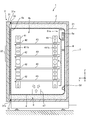
- the culture apparatus 1 includes a shelf plate 43, a shelf holder 42, and a shelf column 41 in the culture chamber 4 b.
- this culture chamber 4b for example, cultures such as cells and microorganisms are cultured.
- the culture chamber 4 b is formed inside the inner box 4, and the inner box 4 is accommodated inside the outer box 2 in a state insulated from the outside air.
- the inner box 4 is a substantially rectangular box made of, for example, stainless steel
- the outer box 2 is a box made of, for example, stainless steel and substantially similar to the inner box 4.
- An inner door 4a is provided at an opening on the front side (+ Y side) of the inner box 4 so as to be opened and closed via a predetermined hinge (not shown).
- the inner door 4a is made of, for example, tempered glass and has a flat plate shape. When the inner door 4a is closed with a packing (not shown) with respect to the opening of the inner box 4, the inside of the inner box 4 becomes airtight with respect to the outside.
- An outer door 3 is provided at an opening on the front side of the outer box 2 so as to be opened and closed via a predetermined hinge (not shown).
- the outer door 3 is made of, for example, metal and has a flat plate shape.
- the shelf plate 43 is a plate member made of, for example, stainless steel for placing the culture.
- the shelf receiver 42 is a member made of, for example, stainless steel for supporting the shelf plate 43 and holding the shelf plate 43 horizontally (parallel to the XY plane), and is arranged on one side (+ X side) of the culture chamber 4b.
- the longitudinal direction is disposed in the horizontal direction (Y-axis direction).
- the shelf receiver 42 and a shelf receiver 42 ′ (see FIG. 8 described later) disposed on the other side surface ( ⁇ X side) of the culture chamber 4b are located at the center between the opposing side surfaces in the culture chamber 4b. They have mirror-symmetric shapes with respect to a plane (not shown) parallel to the side surface.
- the shelf receivers 42 and 42 ′ are provided as a pair on the left and right sides in the X direction so as to support the shelf plate 43.
- the description of the shelf receiver 42 ′ is omitted because it is the same as the description of the shelf receiver 42 except for the description with reference to FIG.
- a heat insulating material (not shown) for heat insulation is provided on the inner surface of the outer box 2, and an air circulation path is provided between the heat insulating material and the inner box 4 for further heat insulation.
- the air jacket 6 is formed.
- the air jacket 6 is provided with a heater (not shown) for adjusting the temperature in the culture chamber 4b.
- a sensor (not shown) for detecting the temperature in the culture chamber 4b is injected on the outer surface of the rear side ( ⁇ Y side) of the outer box 2, and a gas such as carbon dioxide is injected into the culture chamber 4b.
- a sensor box 7 having a nozzle (not shown) and a sensor (not shown) for detecting the concentration of carbon dioxide or the like in the culture chamber 4b.
- the outer door 3 includes a metal door body 31 provided with a heat insulating material (not shown) for keeping warm, a heater (not shown) for adjusting the temperature in the culture chamber 4b, and the like, It has packing 33 attached to convex part 31a facing the opening of outer case 2 in door body 31.
- the outer door 3 further has a control panel 32 on the front side of the door body 31.
- the control panel 32 has keys (not shown) for setting the temperature in the culture chamber 4b, the concentration of carbon dioxide, and the like, and a display (not shown) for displaying these current values.
- the air on the shelf plate 43 side above the culture chamber 4b is sucked into the inlet 51a by the rotation of the fan 5a in a certain direction. And then flows into the duct 44 from the upper side to the lower side and is humidified by the humidified water in the humidifying tray 45, and then the humidified air passes through the hole 46a on the front side of the cover 46. Thus, it returns to the shelf plate 43 side.
- the inside of the culture chamber 4b is maintained at, for example, a substantially uniform temperature, humidity, and gas concentration such as carbon dioxide.
- the gas generator 47 includes, for example, a tank (not shown) for storing hydrogen peroxide solution (an aqueous solution in which hydrogen peroxide gas is dissolved), and an ultrasonic wave for atomizing the hydrogen peroxide solution in the tank. And a vibrator (not shown).
- the folding plate 411 is formed into a mountain fold when viewed from the folding plate 411 toward the contact piece 413 with a center line 411a in the width direction (Y-axis direction) orthogonal to the longitudinal direction (Z-axis direction) as a fold. It is a bent plate-shaped member.
- the bending angle ⁇ shown in FIG. 3A is, for example, 170 degrees.
- the bent plate 411 has a plurality of rectangular insertion holes 411b along the center line 411a, for example, at regular intervals.
- the bent plate 411 has a hole 411c having a shape in which circles with different diameters shifted from the center are overlapped at both ends in the Z-axis direction.
- the pair of side pieces 412 is a plate-like member that is bent while being connected to both side ends along the Y-axis direction of the bending plate 411 and extends substantially in the X-axis direction.
- the pair of side pieces 412 are bent in a direction in which the gap along the Y-axis direction becomes narrower as the distance from the folding plate 411 to the side surface of the culture chamber 4b decreases.
- the shelf column 41 has a mountain-shaped cross-sectional shape in which the side surface on the side supporting the pair of shelf receivers 42, 42 'swells in the center, The side surface on the side supporting the receivers 42, 42 'is bent at the center.
- the shelf support 42 is formed by, for example, punching and bending a single plate member. It is.
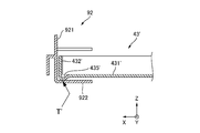
- the shelf receiver 42 includes a vertical plate 421 (the other piece) and a placement piece 422 (one piece). Further, the shelf receiver 42 includes a guide piece 423, a pair of locking pieces 424 and locking pieces 425, and a stop piece 426.
- the mounting piece 422 is bent in the direction away from the side surface of the culture chamber 4b (ie, the direction approaching the shelf plate 43) ( ⁇ X direction) while being connected to the lower end ( ⁇ Z side end) of the vertical plate 421. It is a plate-like member that forms an angle ⁇ ′ with respect to the vertical plate 421 and extends obliquely upward (+ Z side) from the side surface of the culture chamber 4 b toward the inside, and supports the shelf plate 43.
- the bending angle ⁇ ′ shown in FIG. 3A is, for example, 80 degrees. That is, as is apparent from FIG. 4A, each of the pair of shelf supports 42 and 42 ′ has a cross-sectional shape in which the angle between the vertical plate 421 and the mounting piece 422 is an acute L-shape. Presents.
- the guide piece 423 is a plate-like member that is bent in a direction away from the side surface of the culture chamber 4 b while being connected to the upper end (+ Z side end) of the vertical plate 421, and extends orthogonally to the vertical plate 421.
- the locking piece 424 is a tongue piece defined by three-side gaps 424a, 424b, and 424c at the front end (+ Y side) end of the vertical plate 421 and connected by a fold line 424d on one side, This tongue piece is bent at a fold 424d in a direction approaching the side surface of the culture chamber 4b (+ X direction), and extends in an up-down direction in an L shape.
- the bottom plate 431 is a plate-like member that is bent 90 ° or more downward ( ⁇ Z side) while connecting to the + Y side end of the 431, and the back piece 434 is connected to the ⁇ Y side end of the bottom plate 431 and 90 ° or more upward. It is a bent plate-shaped member.
- the bottom plate 431 has a plurality of holes 431a through which air circulating in the culture chamber 4b passes.
- the two shelf columns 41 are arranged in parallel in the horizontal direction (Y-axis direction) along the side surface of the culture chamber 4 b, and the shelf holder 42 has a height.
- the locking piece 424 and the locking piece 425 are respectively locked to the pair of equal insertion holes 411b, thereby being held in the horizontal direction along the side surface of the culture chamber 4b.
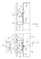
- a surface (+ X side) closer to the side surface of the culture chamber 4 b in the pair of contact pieces 413 of the shelf column 41 and the inner surface of the inner box 4 are lines along the longitudinal direction.
- Each line is in contact with Q.
- the + X side end of the lower surface of the bottom plate 431 is in line contact with a line T along the front-rear direction (Y-axis direction).
- the shelf plate 43 is mounted on the pair of shelf receivers 42 and 42 'with a mirror-symmetrical relationship with a plane parallel to the side surface (not shown) at the center between the opposing side surfaces in the culture chamber 4b.
- the tip of the placement piece 422 ′ at the time of placement placed on the side away from the side surface of the culture chamber 4b (+ X side) and the ⁇ X side end of the lower surface of the bottom plate 431 are in line contact with a line T along the front-rear direction is doing. That is, when the shelf 43 is placed on the pair of shelf receivers 42 and 42 ′, the pair of placement pieces 422 and 422 ′ extends obliquely upward as the distance from the side surfaces of the culture chamber 4 b increases.
- the shelf plate 43 is held horizontally while both side ends of the lower surface thereof are in line contact with the tips of the placement piece 422 and the placement piece 422 ′.
- the position of the shelf 43 in the front-rear direction (Y-axis direction) in the culture chamber 4b is the rear end ( ⁇ Y side end) of the bottom plate 431 of the shelf 43. It is determined by making line contact with and abutting on the stop piece 426 of 42. This line contact is due to the back piece 434 of the shelf plate 43 being bent 90 degrees or more upward (+ Z side) while being connected to the rear side end ( ⁇ Y side end) of the bottom plate 431. This line contact also leads to an improvement in the sterilizing effect of the culture apparatus 1 and the like.
- the pair of mounting pieces 422 and 422 ′ extend obliquely upward as they are separated from the respective side surfaces of the culture chamber 4b (angle ⁇ ′ ( ⁇ 90 degrees in FIG. 4A)).
- angle ⁇ ′ ⁇ 90 degrees in FIG. 4A
- the mounting piece 422 is bent so as to be orthogonal to the vertical plate 421, the tip on the side separated from the side surface of the culture chamber 4b is bent again, for example, upward (+ Z side), and the shelf is placed at the tip. It may be in line contact with the lower surface of the bottom plate 431 of the plate 43.
- the inner surface of the inner box 4, the shelf column 41, the shelf holder 42, and the shelf plate 43 are in line contact with each other with lines P, Q, R, S, and T. Is not to be done.
- the contact may be a point contact.
- 10 is a view of the inner surface of the inner box 4, the shelf column 81, and the shelf support 82 as viewed from the same direction as FIG. 7, and
- FIG. 11 is an inner surface of the inner box 4 in the same cross section as FIG.
- FIG. 6 is a cross-sectional view of the shelf column 81, the shelf receiver 82, and the shelf board 43.
- the inner surface of the inner box 4 is in point contact at a point Q ′.
- a substantially hemispherical protrusion 811a on the surface (parallel to the YZ surface) of the flat plate 811 of the shelf column 81 that is separated from the side surface of the culture chamber 4b (+ X side), and + X of the vertical plate 821 of the shelf support 82 Point contact is made with the side surface at point P ′.
- the substantially hemispherical protrusion 822 a on the upper surface (parallel to the XY surface) of the mounting piece 822 of the shelf receiver 82 and the + X side end of the lower surface of the bottom plate 431 of the shelf plate 43 are Point contact is made at point T ′′.
- protrusions 811a, 811b, 813a, and 822a illustrated in FIGS. 10 and 11 are formed with a tool similar in shape to the protrusion from the surface opposite to the side on which the protrusion is formed, for example, with respect to the plate member. What is necessary is just to form by pressing to such an extent that a permite
- the temperature in the culture chamber and the concentration of gas such as carbon dioxide (CO 2 ) and oxygen (O 2 ) are maintained constant, and the culture chamber is sterilized to culture cultures such as cells and microorganisms. Is done.
- the gas concentration in the culture chamber is detected by a sensor, and the gas supply into the culture chamber is controlled so that the gas concentration is kept constant.
- an atmospheric gas mainly composed of air in the culture chamber hereinafter simply referred to as gas
- the gas concentration is detected by a sensor and then returned to the culture chamber.
- a suction device such as a pump or a fan is used to suck the gas from the culture chamber into the pipe and return it to the culture chamber again (see, for example, JP-A-2007-259715).
- the suction device As described above, by using the suction device, the gas in the culture chamber can be forcibly guided to the pipe, and the flow rate of the gas in the pipe can be controlled to a speed suitable for detection by the sensor.
- the suction device As the suction device is required, the cost and power consumption increase, and if the suction device fails, the gas concentration cannot be detected accurately, making it difficult to maintain a constant gas concentration in the culture chamber. End up. Then, this invention aims at detecting the density
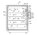
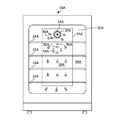
- a culture chamber 26A The space in the inner box 14A sealed by the inner door 20A is a culture chamber 26A.
- a shelf 28A having a large number of ventilation holes is provided in the culture chamber 26A, and the container containing the culture is placed on the shelf 28A with the outer door 22A and the inner door 20A being opened. Then, the culture placed on the shelf 28A is cultured in the culture chamber 26A with the outer door 22A and the inner door 20A being closed. During culture, only the outer door 22A is opened, and the inside of the culture chamber 26A can be observed with the inner door 20A closed.
- a fan (sirocco fan) 32A for circulating the gas in the culture chamber 26A is provided on the back surface 30A in the inner box 14A.
- a motor 33A for driving the fan 32A is provided in the space 18A.
- a wall plate 34A is provided so as to cover a part of the fan 32A and the back surface 30A.
- the wall plate 34A is provided with a suction port 36A in the vicinity of a portion covering the fan 32A, and a duct 38A (air passage) through which the gas sucked from the suction port 36A flows is formed.
- the gas in the culture chamber 26A is sucked from the suction port 36A above the back surface 30A by the rotation of the fan 32A, flows from the top to the bottom in the duct 38A, and returns to the culture chamber 26A from below the back surface 30A.
- the gas discharged from the lower portion of the duct 38A flows through the ventilation hole of the shelf 28A from the bottom surface 40A of the inner box 14A toward the top surface 42A, and is sucked again from the suction port 36A. Thereby, the gas in the culture chamber 26A circulates.
- a flexible tube 56A connection pipe
- a flexible tube 56A is inserted into the through holes 52A and 54A from the back surface 44A side of the outer box 12A so that the outer periphery of the tube 56A is in close contact with the inner periphery of the through holes 52A and 54A. ing. That is, the gas in the culture chamber 26A can be circulated through the tube 56A.
- a concentration sensor 58A for detecting the concentration of the CO 2 gas flowing in the tube 56A is provided at a portion of the tube 56A protruding outside the outer box 12A.
- an infrared type can be used for the density sensor 58A. In the case of the infrared type, by heating the ceramic heater, an infrared ray of about 4.3 ⁇ m absorbed by the CO 2 gas is generated and irradiated to the gas flowing through the tube 56A, and the amount of infrared light that has passed through the gas is received by the light receiving element. By detecting, the concentration of CO 2 gas can be measured.
- a sensor other than the infrared type such as a heat conduction type, can be used as the concentration sensor 58A.
- the portion of the tube 56A that protrudes to the outside of the outer box 12A exists in a closed space 61A that is covered with a heater 60A (heating device).
- the temperature is maintained at about 37 ° C. and the humidity is about 95%.
- the inside of the tube 56A may be condensed. Therefore, the inside of the closed space 61A where the portion protruding outside the outer box 12A of the tube 56A exists is heated and maintained at about 45 ° C., for example, by the heater 60A.
- the temperature inside the closed space 61A constant, there is an effect of making the sensitivity of the density sensor 58A constant.
- the injection port 48A is disposed upstream of the through holes 52A and 54A in the gas flow direction in the duct 38A.
- the injection port 48A is disposed so as to inject CO 2 gas toward the left side toward the back surface 30A at a position shifted to the left side toward the back surface 30A from the position connecting the fan 32A and the through holes 52A and 54A. ing. That is, the CO 2 gas is injected from the injection port 48A in a direction different from the flow direction of the gas circulating in the culture chamber 26A.
- the CO 2 gas injected from the injection port 48A flows downward from the inside of the duct 38A while being mixed with the gas sucked from the suction port 36A by the air flow of the fan 32A, and is supplied to the culture chamber 26A. Since the injection port 48A is disposed at a position close to the fan 32A, the CO 2 gas injected from the injection port 48A is easily stirred, and a response when adjusting the concentration of the CO 2 gas in the culture chamber 26A. The sex can be improved. Further, since the direction in which the CO 2 gas is injected from the injection port 48A is different from the direction of gas flow in the duct 38A, the high-concentration CO 2 gas injected from the injection port 48A passes through the through holes 52A and 54A. Direct flow into the vicinity is suppressed, and the detection accuracy of the concentration of CO 2 gas in the culture chamber 26A can be improved.
- the graph shown by the solid line in FIG. 15 shows the CO when the outer door 22A and the inner door 20A are opened for 30 seconds and then closed from the state where the CO 2 gas concentration in the culture chamber 26A is maintained at about 5%. It shows a transition of 2 gas concentration.
- the graph shown with the continuous line of FIG. 16 makes the open time of the outer door 22A and the inner door 20A 60 seconds.
- the graphs shown by the broken lines in FIGS. 15 and 16 are the same as those of the culture apparatus 10A except that a pump is provided that sucks the gas in the culture chamber 26A from the through hole 52A and returns it to the through hole 54A. Shows the transition of the CO 2 gas concentration.
- the control device 72A controls the opening and closing of the valve 70A based on the detection value of the concentration sensor 58A, thereby returning the CO 2 gas concentration in the culture chamber 26A to about 5%.
- the time for the CO 2 gas concentration to return to about 5% after the outer door 22A and the inner door 20A are closed is also used in the culture apparatus 10A of this embodiment that does not include a pump. It is almost the same as the configuration provided.
- the culture apparatus 10A does not include a suction device such as a pump, the gas flows through the tube 56A at a speed suitable for detection by the concentration sensor 58A, and the CO 2 gas concentration can be detected with high accuracy.
- the duct 38A is provided on the back surface 30A side of the inner box 14A, but may be provided on the side surface side.
- the fan 32A may be disposed on the top surface 42A of the inner box 14A, and the through holes 52A and 54A may be provided on the back surface 30A or the side surface of the inner box 14A. Further, the through holes 52A and 54A may be provided on the top surface of the inner box 14A.
- the through holes 52A and 54A are arranged on the same straight line as viewed from the fan 32A, but may not be on the same straight line as long as the flow rates are different. Further, the through holes 52A and 54A may be provided on different surfaces instead of the same surface in the inner box 14A.
- pillar 41, shelf receptacles 42 and 42 ', and the shelf board 43 of 1st Embodiment are fully sterilized with sterilization gas in the inner box 14A. It may be adopted.
- the culture apparatus for culturing a culture such as cells and microorganisms in a culture chamber.
- the culture apparatus includes a fan that circulates air in the culture chamber and a duct that guides the air circulated in the culture chamber from the upper side to the lower side of the culture chamber.
- a fan circulates the air in the culture chamber to maintain a uniform concentration of gas such as carbon dioxide in the air in the culture chamber, or to maintain a uniform temperature higher than the outside air temperature in the culture chamber, for example.
- gas such as carbon dioxide
- air discharged downward from the duct with a fan as a driving force for example, by turning upward the direction of the airflow at the water surface of the humidifying tray placed on the bottom surface of the culture chamber, The humidity of the culture placed in this updraft is maintained.
- hydrogen peroxide (H 2 O 2 ) gas having a sterilizing effect is generated in order to sterilize the previous culture or bacteria caused by this, and the culture chamber is filled with hydrogen peroxide gas at a predetermined concentration. It may satisfy and maintain this state for a predetermined time.
- a gas generator that generates hydrogen peroxide gas has been disclosed (for example, see Japanese Patent Application No. 2007-259715).
- This gas generator has a tank in which hydrogen peroxide solution (aqueous solution in which hydrogen peroxide is dissolved) is stored and an ultrasonic vibrator that atomizes the hydrogen peroxide solution to generate gas. Hydrogen peroxide gas is generated by the vibration of the sonic transducer.
- the humidifying tray used at the time of culturing was removed from the bottom surface of the culture chamber, and a gas generator filled with a hydrogen peroxide solution was placed on the bottom surface and sealed.
- the ultrasonic vibrator of the gas generator is operated for a predetermined time in the culture chamber.
- FIG. 17 is a side sectional view of an example of the culture device 1B of the third embodiment.
- FIG. 18A is a plan view of an example of the gas generator 10B of the third embodiment.
- FIG. 18B is a partial cross-sectional view taken along the line AA ′ of the gas generator 10B of FIG.
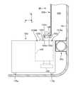
- FIG. 19 is an enlarged view of the gas generator 10B of FIG. 17 and the vicinity thereof.
- the culture apparatus 1B includes a duct 43B, a fan 5Ba, and a gas generator 10B.
- this culture apparatus 1B cultures cultures, such as a cell and a microorganism, in the culture chamber 4Bb of the inner box 4B.
- the inner box 4B is a substantially rectangular box made of, for example, stainless steel, and a culture chamber 4Bb is formed therein.
- the inner box 4B is provided with an inner door 4Ba whose opening can be opened and closed via a predetermined hinge (not shown).
- the inner door 4Ba is made of, for example, tempered glass and has a flat plate shape.
- the culture chamber 4Bb illustrated in FIG. 17 is partitioned in the vertical direction (Z-axis direction) by a plurality of, for example, stainless steel shelves 42B for placing the culture.
- the shelf 42B has a plurality of holes (not shown) penetrating in the vertical direction, and is supported by, for example, a stainless steel shelf receiver 41B provided in pairs on the inner surface of the inner box 4B on the ⁇ X side. .
- the duct 43B is composed of, for example, a rear side wall ( ⁇ Y side) of the inner box 4B and a stainless steel wall plate 5B, and forms an air passage between them.
- the wall plate 5B illustrated in FIG. 17 is divided into an upper upper end portion 51B, a central portion 52B, and a lower lower end portion 53B.
- the upper end 51B is shaped to surround the fan 5Ba with a predetermined distance from the blades and has a suction port 51Ba.
- the central portion 52B has a horizontal section (X, Y axis direction) having a portion that contacts the inner surface of the rear side of the inner box 4B on the ⁇ X side and a portion that faces the inner surface with a certain distance therebetween. It has a U shape.
- the lower end 53B is a short piece that is bent at the lower end of the flat plate portion along the vertical direction and extends in the horizontal direction + Y side, and is separated from the bottom surface of the inner box 4B by a predetermined distance in the vertical direction.
- an ultraviolet lamp 5Bb for irradiating the air passing through the duct 43B with ultraviolet rays is attached to the inner surface of the duct 43B illustrated in FIG. 17 (on the ⁇ Z side) and the rear side of the inner box 4B.
- the fan 5Ba is, for example, a sirocco fan provided with the Y-axis direction as a rotation axis with respect to the inner surface of the upper side (+ Z side) of the duct 43B and the rear side of the inner box 4B.
- a predetermined power source such as a motor
- the air in the culture chamber flows into the duct 43B through the suction port 51Ba, and flows in the duct 43B from above to below.
- a circulation path returning to the culture chamber through the opening below 43B is formed.
- the inner box 4B described above is accommodated in an outer box 2B having a substantially rectangular shape made of, for example, stainless steel.
- the outer box 2B is a box made of, for example, metal and substantially similar to the inner box 4B, and a heat insulating material (not shown) for heat insulation is provided inside thereof.
- a heat insulating material (not shown) for heat insulation is provided inside thereof.
- an air jacket 6B as an air circulation path is formed for further heat insulation.
- the air jacket 6B has a temperature in the culture chamber 4Bb.
- a heater (not shown) for adjustment is attached.
- the outer box 2B is provided with an outer door 3B that can be opened and closed through a predetermined hinge (not shown).
- the outer door 3B includes a metal door body 31B provided with a heat insulating material (not shown) for heat insulation, a heater (not shown) for adjusting the temperature in the culture chamber 4Bb, and the like, and the door. It has packing 33B attached to convex part 31Ba facing the opening of outer box 2B in main part 31B.
- the outer door 3B further has a control panel 32B on the front side of the door body 31B.
- the control panel 32B has, for example, a key for setting the temperature in the culture chamber 4Bb, the concentration of carbon dioxide, a display for displaying these current values, etc., and the temperature, concentration, etc. It has a control part (not shown) which controls a sensor etc. for detecting this.
- a sensor for example, a sensor (not shown) for detecting the temperature in the culture chamber 4Bb, a sensor (not shown) for detecting the concentration of carbon dioxide, a heater (not shown)
- a sensor box 7B having an illustration) is provided on the outer surface on the rear side of the outer box 2B.
- These sensors are attached from the outside of the outer box 2B through, for example, a hole (not shown) drilled from the outer surface on the rear side of the outer box 2B to the inner surface on the rear side of the inner box 4B.
- these sensors are electrically connected to the control unit included in the control panel 32B described above via predetermined wiring (not shown).
- This control unit controls the operation of the heater, the fan 5Ba, the ultrasonic vibrator 15B of the gas generator 10B, and the like. Further, the outer surface of the rear side of the outer box 2B and the sensor box 7B are covered with a cover 21B having a heat insulating material (not shown) on the inner side.
- the gas generator 10B of the present embodiment includes a tank 14B in which hydrogen peroxide solution is stored, and a gas ( And an opening 121B of the tank 14B.
- the opening 121B has an inlet 121Ba for introducing air into the tank 14B, and hydrogen peroxide gas from the tank 14B. It is divided into the discharge port 121Bb which discharges
- the suppression plate 13B, the locking pin 13Ba, and the ultrasonic transducer 15B illustrated in FIG. 18B and FIG. 19 are not a cross-section at AA ′ but an X-axis for convenience of the following description. It represents the side as seen in the direction.
- a substantially rectangular opening top plate 12B made of metal has a tank 14B with an ultrasonic transducer 15B attached downward ( ⁇ Z side) and an opening 121B upward (+ Z side).
- a wiring connector 19B for supplying power from a power source is attached to the side surface on the + X side of the open housing 11B.
- the space defined by the opening top plate 12B to which the tank 14B is attached and the opening housing 11B is airtight to the outside.
- an ultrasonic transducer 15B, a control board 16B that controls the operation of the ultrasonic transducer 15B, a wiring 17B that electrically connects the ultrasonic transducer 15B and the control board 16B, and a control A wiring 18B that electrically connects the substrate 16B and the wiring connector 19B is accommodated.
- a suppression plate 13B is provided upright at a substantially central portion in the Y-axis direction around the opening 121B of the opening top plate 12B.
- the opening 121B is divided into an introduction port 121Ba and a discharge port 121Bb.
- the suppression plate 13B has a function of suppressing the air discharged from the duct 43B from flowing into the discharge port 121Bb, and the gas generator 10B is connected to the wall plate in order to effectively flow the air into the introduction port 121Ba. It has a function of fixing to a suitable position with respect to 5B.
- the suppression plate 13B includes, for example, a substantially rectangular horizontal portion 131B, a vertical portion 132B orthogonal to the horizontal portion 131B along the X-axis direction, both ends of the vertical portion 132B, and the X-axis direction. It is a metal plate member integrally having a pair of horizontal pieces 133B orthogonal to each other and parallel to the horizontal portion 131B. The pair of horizontal pieces 133B are fixed around the opening 121B so that the vertical portion 132B is positioned at a substantially central portion of the opening 121B in the Y-axis direction. Further, the ⁇ X side through hole 13Bb of the horizontal portion 131B is provided with a pair of locking pins 13Ba made of a substantially conical shape, for example, downward ( ⁇ Z side).
- the lower end portion 53B of the wall plate 5B has a pair of locking holes 53Ba along the X-axis direction.
- the pair of locking holes 53Ba are located on both sides along the X-axis direction in the lower end portion 53B of the wall plate 5B, for example.
- the distance between the centers of the two locking holes 53Ba is set equal to the distance between the centers of the two locking pins 13Ba illustrated in FIG.
- the maximum diameter of the conical portion of the locking pin 13Ba is set slightly smaller than the diameter of the locking hole 53Ba.
- gas is generated by inserting the pair of locking pins 13Ba of the suppression plate 13B into the pair of locking holes 53Ba of the lower end portion 53B of the wall plate 5B.
- the lower end portion 53B of the wall plate 5B and the horizontal portion 131B of the suppression plate 13B overlap each other in the Y-axis direction, and a horizontal portion approximately at the center of the lower end portion 53B in the X-axis direction. The positional relationship where 131B is located is taken.
- the inlet 121Ba is located on the duct 43B side, and the outlet 121Bb is located on the shelf 42B side.
- the gas generator 10B can be removed from the duct 43B by slightly lifting the suppression plate 13B and removing the pair of locking pins 13Ba from the pair of locking holes 53Ba.
- four legs 11Ba having a substantially conical shape, for example, downward are provided at the four corners of the substantially rectangular outer surface on the lower side of the opening housing 11B. Each is in point contact with the bottom surface of the culture chamber 4Bb.
- a sensor 14Ba is provided for detecting the level of the hydrogen peroxide solution.
- the sensor 14Ba has, for example, a pair of metal pins, and these pair of metal pins are provided so as to protrude inward from the inner surface of the tank 14B at a predetermined interval in the Z-axis direction. For example, when the control unit measures the resistance value between the pair of metal pins and determines that the water level of the hydrogen peroxide solution in the tank 14B does not reach the predetermined value based on the measurement result, The operation of the acoustic wave vibrator 15B is prohibited.
- the cell is connected to the power source described above, for example, a male connector (not shown) of the wiring (not shown) from the wiring connector 19B of the gas generator 10B.
- the wiring (not shown) in 4Bb is connected to, for example, a female connector (not shown) to be electrically connected.
- This pair of connectors has water resistance and corrosion resistance.
- the connected male connector and female connector may be removed.
- FIG. 20 is a schematic diagram illustrating an example of an air path in the culture chamber 4Bb during the culture of the culture apparatus 1B of FIG.
- FIG. 21 is a schematic diagram showing an example of an air path in the culture chamber 4Bb in the sterilization operation of the culture apparatus 1B of FIG.
- a humidifying tray 44B made of, for example, stainless steel containing humidified water is disposed on the bottom surface in the culture chamber 4Bb so that a part thereof is located directly below the duct 43B.
- the entire humidifying tray 44B is covered with, for example, a stainless steel cover 45B having a hole 45Ba on the front side.
- the air on the shelf 42B above the culture chamber 4Bb flows into the duct 43B through the suction port 51Ba, and moves downward in the duct 43B from above. Then, the humidified air flows forward on the surface of the humidified water and passes through the hole 45Ba of the cover 45B to form a rising airflow surrounding the plurality of shelves 42B. Then, the air that has risen above the culture chamber 4Bb flows again into the duct 43B through the suction port 51Ba.
- the inside of the culture chamber 4Bb is maintained at, for example, a substantially uniform temperature, humidity, and carbon dioxide concentration.
- the gas generator 10B storing the hydrogen peroxide solution in the tank 14B is placed in the culture chamber 4Bb so that the relative position shown in FIG. Place on the bottom.
- the air on the shelf 42B above the culture chamber 4Bb flows into the duct 43B through the suction port 51Ba, and moves downward in the duct 43B from above.
- At least part of the gas enters the tank 14B through the inlet 121Ba of the gas generator 10B, turns the direction of the air flow upward on the surface of the hydrogen peroxide solution, and operates the ultrasonic vibrator 15B.
- the discharge port 121Bb of the gas generator 10B is discharged from the discharge port 121Bb of the gas generator 10B to form an updraft surrounding the plurality of shelves 42B. Then, the air that has risen above the culture chamber 4Bb flows again into the duct 43B through the suction port 51Ba.
- the uniformity of the hydrogen peroxide gas in the culture chamber 4Bb can be improved by using the fan 5Ba and the duct 43B (see FIG. 20) used during the culture. it can. That is, since the hydrogen peroxide gas is released above the culture chamber 4Bb by the circulating airflow formed by the fan 5Ba and the duct 43B (see FIG. 21), the specific gravity is larger than that of the air and stagnation below the culture chamber 4Bb. The uniformity of the hydrogen peroxide gas in the culture chamber 4Bb is improved. This leads to an improvement in the sterilizing effect of the culture apparatus 1B.
- the air discharged from the discharge port 121Bb flows downward through the duct 43B, for example. It is effectively discharged above the culture chamber 4Bb without being disturbed by air.
- the gas generator 10B can be disposed at a suitable position with respect to the duct 43B in order to effectively introduce the air from the duct 43B into the tank 14B by the above-described engagement between the suppression plate 13B and the lower end portion 53B. As described above, the uniformity of the hydrogen peroxide gas in the culture chamber 4Bb is further improved, and thus the sterilizing effect of the culture apparatus 1B is further improved.
- the duct 43B is composed of the wall on the rear side of the inner box 4B and the wall plate 5B, but is not limited thereto.
- the duct 43B does not occupy the culture chamber 4Bb too much, does not interfere with the culture of the culture, guides the air from the fan 5Ba from the upper side of the culture chamber 4Bb, and is easy to sterilize. Any configuration may be employed, and any location in the culture chamber 4Bb may be provided.
- the engagement between the duct 43B and the suppression plate 13B of the gas generator 10B is via the pair of locking holes 53Ba and the pair of locking pins 13Ba in the lower end portion 53B of the wall plate 5B.
- the attachment / detachment means between the duct 43B and the suppression plate 13B may have any configuration as long as it has a simple shape that is easy to sterilize, for example.
- pillar 41, shelf holders 42 and 42 ', and the shelf board 43 of 1st Embodiment are fully sterilized with sterilization gas in the inner box 4B. It may be adopted.
Landscapes
- Health & Medical Sciences (AREA)
- Chemical & Material Sciences (AREA)
- Life Sciences & Earth Sciences (AREA)
- Wood Science & Technology (AREA)
- Organic Chemistry (AREA)
- Engineering & Computer Science (AREA)
- Bioinformatics & Cheminformatics (AREA)
- Zoology (AREA)
- Biomedical Technology (AREA)
- Genetics & Genomics (AREA)
- Microbiology (AREA)
- Biotechnology (AREA)
- Biochemistry (AREA)
- General Engineering & Computer Science (AREA)
- General Health & Medical Sciences (AREA)
- Sustainable Development (AREA)
- Physics & Mathematics (AREA)
- Thermal Sciences (AREA)
- Analytical Chemistry (AREA)
- Clinical Laboratory Science (AREA)
- Molecular Biology (AREA)
- Apparatus Associated With Microorganisms And Enzymes (AREA)
Priority Applications (4)
| Application Number | Priority Date | Filing Date | Title |
|---|---|---|---|
| EP09807479.2A EP2180037A4 (en) | 2008-08-27 | 2009-08-20 | CULTURE SYSTEM |
| US12/707,122 US8216830B2 (en) | 2008-08-27 | 2010-02-17 | Culture apparatus |
| US13/527,054 US8557572B2 (en) | 2008-08-27 | 2012-06-19 | Culture apparatus |
| US13/527,027 US8663979B2 (en) | 2008-08-27 | 2012-06-19 | Culture apparatus |
Applications Claiming Priority (2)
| Application Number | Priority Date | Filing Date | Title |
|---|---|---|---|
| JP2008218615A JP5011488B2 (ja) | 2008-08-27 | 2008-08-27 | 培養装置 |
| JP2008-218615 | 2008-08-27 |
Related Child Applications (1)
| Application Number | Title | Priority Date | Filing Date |
|---|---|---|---|
| US12/707,122 Continuation US8216830B2 (en) | 2008-08-27 | 2010-02-17 | Culture apparatus |
Publications (1)
| Publication Number | Publication Date |
|---|---|
| WO2010024182A1 true WO2010024182A1 (ja) | 2010-03-04 |
Family
ID=41721350
Family Applications (1)
| Application Number | Title | Priority Date | Filing Date |
|---|---|---|---|
| PCT/JP2009/064595 Ceased WO2010024182A1 (ja) | 2008-08-27 | 2009-08-20 | 培養装置 |
Country Status (4)
| Country | Link |
|---|---|
| US (3) | US8216830B2 (enExample) |
| EP (1) | EP2180037A4 (enExample) |
| JP (1) | JP5011488B2 (enExample) |
| WO (1) | WO2010024182A1 (enExample) |
Cited By (1)
| Publication number | Priority date | Publication date | Assignee | Title |
|---|---|---|---|---|
| CN109321461A (zh) * | 2018-11-19 | 2019-02-12 | 袁永华 | 一种便于调节的细胞工程用细胞培养装置 |
Families Citing this family (14)
| Publication number | Priority date | Publication date | Assignee | Title |
|---|---|---|---|---|
| JP5727187B2 (ja) * | 2010-09-30 | 2015-06-03 | パナソニックヘルスケアホールディングス株式会社 | インキュベータ |
| JP5897855B2 (ja) * | 2011-09-22 | 2016-04-06 | パナソニックヘルスケアホールディングス株式会社 | ヒーターを備えた培養装置 |
| CN105531362B (zh) | 2013-10-11 | 2017-09-29 | 松下健康医疗控股株式会社 | 培养装置 |
| CN105555944B (zh) * | 2013-10-11 | 2017-03-15 | 松下健康医疗控股株式会社 | 培养装置 |
| CN105555943B (zh) | 2013-10-11 | 2017-06-30 | 松下健康医疗控股株式会社 | 培养装置 |
| EP3031899B1 (en) * | 2013-10-11 | 2018-09-19 | PHC Holdings Corporation | Culture apparatus |
| DE102014011941B3 (de) | 2014-08-14 | 2015-08-20 | Ika-Werke Gmbh & Co. Kg | Einlegeboden und Inkubator |
| WO2016158337A1 (ja) * | 2015-03-30 | 2016-10-06 | パナソニックヘルスケアホールディングス株式会社 | 培養装置 |
| JP6412637B2 (ja) * | 2015-03-31 | 2018-10-24 | Phcホールディングス株式会社 | 培養装置 |
| JP6784779B2 (ja) | 2017-01-23 | 2020-11-11 | Phcホールディングス株式会社 | 収納装置 |
| US11518972B2 (en) * | 2017-05-25 | 2022-12-06 | Lun-Kuang Liu | Movable cell incubator |
| EP3825395B1 (en) * | 2018-09-06 | 2022-07-06 | PHC Corporation | Culture device |
| JP7638822B2 (ja) | 2021-08-11 | 2025-03-04 | エスペック株式会社 | 環境試験装置 |
| US20240270924A1 (en) * | 2023-02-09 | 2024-08-15 | Laura KOLINSKY | Residential Plastic Recycling Unit |
Citations (3)
| Publication number | Priority date | Publication date | Assignee | Title |
|---|---|---|---|---|
| JP2005118021A (ja) * | 2003-10-20 | 2005-05-12 | Sanyo Electric Co Ltd | 培養庫 |
| WO2007111105A1 (ja) * | 2006-03-27 | 2007-10-04 | Sanyo Electric Co., Ltd. | 培養装置 |
| WO2008004533A1 (en) * | 2006-07-05 | 2008-01-10 | Sanyo Electric Co., Ltd. | Shelf device and incubator provided with it |
Family Cites Families (17)
| Publication number | Priority date | Publication date | Assignee | Title |
|---|---|---|---|---|
| US3987133A (en) * | 1975-09-05 | 1976-10-19 | Fisher Scientific Company | Humidifier |
| US4131011A (en) | 1977-02-28 | 1978-12-26 | Abbott Laboratories | Method and device for determining the end point for drying |
| DE2924446C2 (de) | 1979-06-18 | 1982-09-16 | W.C. Heraeus Gmbh, 6450 Hanau | Verfahren und Vorrichtung zum Kultivieren von Zellen und Geweben von Menschen und Tieren oder von Mikroorganismen |
| US4701415A (en) * | 1984-03-02 | 1987-10-20 | Mallinckrodt, Inc. | Controlled atmosphere enclosure |
| JPH0325599Y2 (enExample) * | 1985-03-19 | 1991-06-03 | ||
| JPS63108262A (ja) | 1986-10-24 | 1988-05-13 | Yamato Scient Co Ltd | インキユベ−タにおけるco↓2濃度制御方法 |
| US5418131A (en) * | 1994-04-13 | 1995-05-23 | General Signal Corporation | Humidity compensated carbon dioxide gas measurement and control |
| CA2148211C (en) * | 1994-06-15 | 2006-07-11 | David A. Gloyd | Heated humidifier for incubator |
| US5792427A (en) * | 1996-02-09 | 1998-08-11 | Forma Scientific, Inc. | Controlled atmosphere incubator |
| JPH11108871A (ja) | 1997-10-06 | 1999-04-23 | Sanyo Electric Co Ltd | コーヒー品質測定装置、および該コーヒー品質測定装置を備えたコーヒー自動販売機、コーヒー抽出・保存装置およびコーヒー保存容器 |
| EP1182292A1 (en) | 2000-08-16 | 2002-02-27 | The Procter & Gamble Company | Apparatus for cleaning and refreshing fabrics with an improved ultrasonic nebulizer, and improved ultrasonic nebulizer |
| JP2004000275A (ja) | 2003-08-25 | 2004-01-08 | Sanyo Electric Co Ltd | 培養装置 |
| JP2005274505A (ja) | 2004-03-26 | 2005-10-06 | Tdk Corp | 炭酸ガス濃度測定装置、炭酸ガス濃度測定方法、ならびに燃焼機器 |
| JP2005345146A (ja) | 2004-05-31 | 2005-12-15 | Tdk Corp | 炭酸ガス濃度測定装置、炭酸ガス濃度測定方法、ならびに燃焼機器 |
| JP5337339B2 (ja) * | 2006-03-27 | 2013-11-06 | パナソニックヘルスケア株式会社 | 殺菌庫 |
| AR061224A1 (es) | 2007-06-05 | 2008-08-13 | Tenaris Connections Ag | Una union roscada de alta resistencia, preferentemente para tubos con recubrimiento interno. |
| DE202007012933U1 (de) | 2007-09-14 | 2007-11-29 | VD Werkstätten GmbH & Co. KG | Möbelfrontteil |
-
2008
- 2008-08-27 JP JP2008218615A patent/JP5011488B2/ja not_active Expired - Fee Related
-
2009
- 2009-08-20 EP EP09807479.2A patent/EP2180037A4/en not_active Withdrawn
- 2009-08-20 WO PCT/JP2009/064595 patent/WO2010024182A1/ja not_active Ceased
-
2010
- 2010-02-17 US US12/707,122 patent/US8216830B2/en not_active Expired - Fee Related
-
2012
- 2012-06-19 US US13/527,054 patent/US8557572B2/en not_active Expired - Fee Related
- 2012-06-19 US US13/527,027 patent/US8663979B2/en active Active
Patent Citations (3)
| Publication number | Priority date | Publication date | Assignee | Title |
|---|---|---|---|---|
| JP2005118021A (ja) * | 2003-10-20 | 2005-05-12 | Sanyo Electric Co Ltd | 培養庫 |
| WO2007111105A1 (ja) * | 2006-03-27 | 2007-10-04 | Sanyo Electric Co., Ltd. | 培養装置 |
| WO2008004533A1 (en) * | 2006-07-05 | 2008-01-10 | Sanyo Electric Co., Ltd. | Shelf device and incubator provided with it |
Non-Patent Citations (1)
| Title |
|---|
| See also references of EP2180037A4 * |
Cited By (1)
| Publication number | Priority date | Publication date | Assignee | Title |
|---|---|---|---|---|
| CN109321461A (zh) * | 2018-11-19 | 2019-02-12 | 袁永华 | 一种便于调节的细胞工程用细胞培养装置 |
Also Published As
| Publication number | Publication date |
|---|---|
| JP5011488B2 (ja) | 2012-08-29 |
| US8663979B2 (en) | 2014-03-04 |
| US20100173401A1 (en) | 2010-07-08 |
| EP2180037A4 (en) | 2014-01-08 |
| US20120264201A1 (en) | 2012-10-18 |
| US20120258528A1 (en) | 2012-10-11 |
| JP2010051218A (ja) | 2010-03-11 |
| US8557572B2 (en) | 2013-10-15 |
| EP2180037A1 (en) | 2010-04-28 |
| US8216830B2 (en) | 2012-07-10 |
Similar Documents
| Publication | Publication Date | Title |
|---|---|---|
| JP5011488B2 (ja) | 培養装置 | |
| JP5727187B2 (ja) | インキュベータ | |
| EP4144828A1 (en) | Incubator | |
| WO2018212029A1 (ja) | インキュベータ | |
| JP4916201B2 (ja) | 培養装置 | |
| KR101358500B1 (ko) | 다기능 인큐베이터 | |
| CN1946433A (zh) | 杀菌方法及杀菌装置 | |
| BR102012032763A2 (pt) | Biorecipiente oscilante | |
| KR20110050477A (ko) | 이온 확산 장치 및 이온 발생 카트리지 | |
| EP3260529B1 (en) | Incubator | |
| JP5624711B2 (ja) | 培養装置 | |
| CN102858946B (zh) | 用于照射生物反应器中的介质的生物反应器系统、振动装置和方法 | |
| JP2003107364A (ja) | 顕微鏡観察用培養器 | |
| WO2015119254A1 (ja) | 培養装置 | |
| US10918755B2 (en) | Housing apparatus | |
| WO2010004279A2 (en) | Laboratory apparatus for a controlled environment | |
| JP6753680B2 (ja) | 培養装置 | |
| CN216816207U (zh) | 一种血涂片承托架 | |
| JP5469827B2 (ja) | 培養装置 | |
| CN211339514U (zh) | 一种用于微生物检测的培养器 | |
| CN219546943U (zh) | 一种自动灭菌的氧化碳培养箱 | |
| US20240417666A1 (en) | Culturing apparatus and culture system | |
| KR100936177B1 (ko) | 페트병 가습기용 살균 카트리지 | |
| CN213060880U (zh) | 一种二氧化碳培养箱 | |
| JP2007175012A (ja) | 生物指標作製方法、作製装置及び生物指標 |
Legal Events
| Date | Code | Title | Description |
|---|---|---|---|
| REEP | Request for entry into the european phase |
Ref document number: 2009807479 Country of ref document: EP |
|
| WWE | Wipo information: entry into national phase |
Ref document number: 2009807479 Country of ref document: EP |
|
| 121 | Ep: the epo has been informed by wipo that ep was designated in this application |
Ref document number: 09807479 Country of ref document: EP Kind code of ref document: A1 |
|
| NENP | Non-entry into the national phase |
Ref country code: DE |