WO2010021199A1 - 路面仮復旧用部材及び路面仮復旧工法 - Google Patents
路面仮復旧用部材及び路面仮復旧工法 Download PDFInfo
- Publication number
- WO2010021199A1 WO2010021199A1 PCT/JP2009/061328 JP2009061328W WO2010021199A1 WO 2010021199 A1 WO2010021199 A1 WO 2010021199A1 JP 2009061328 W JP2009061328 W JP 2009061328W WO 2010021199 A1 WO2010021199 A1 WO 2010021199A1
- Authority
- WO
- WIPO (PCT)
- Prior art keywords
- road surface
- mat
- lining mat
- lining
- pin
- Prior art date
- Legal status (The legal status is an assumption and is not a legal conclusion. Google has not performed a legal analysis and makes no representation as to the accuracy of the status listed.)
- Ceased
Links
Images


Classifications
-
- E—FIXED CONSTRUCTIONS
- E01—CONSTRUCTION OF ROADS, RAILWAYS, OR BRIDGES
- E01C—CONSTRUCTION OF, OR SURFACES FOR, ROADS, SPORTS GROUNDS, OR THE LIKE; MACHINES OR AUXILIARY TOOLS FOR CONSTRUCTION OR REPAIR
- E01C9/00—Special pavings; Pavings for special parts of roads or airfields
- E01C9/08—Temporary pavings
Definitions
- the present invention relates to a lining member for temporarily restoring a road surface when excavating the road surface and performing gas, water, sewage and other pipe work, and a road surface temporary restoration method using the lining member. is there.
- the asphalt used in the temporary restoration work eventually becomes industrial waste, and temporary paving in the temporary restoration work is not preferable from the viewpoint of efficiency of construction, resource saving, environmental problems, and the like.
- Patent Document 1 Japanese Patent Laid-Open No. 10-37113
- a pressing member and a rubber mat are used as a temporary restoration member, and a hollow rod-shaped body is substantially parallel to the excavation road surface (pavement removal surface) at a predetermined interval.
- a temporary restoration road surface is disclosed in which a pressing member connected in parallel with the state is placed and a rubber mat wider than the excavation road surface width is placed thereon.
- Patent Document 2 Japanese Patent Application Laid-Open No. 2004-52410 employs a simulated roadbed material and a rubber mat as temporary restoration members.
- the simulated roadbed material is formed of waste plastic, and a rubber mat is laid on the simulated roadbed material. It is what.
- the present invention proposes a new road surface temporary restoration member that simplifies the construction by adopting a simple temporary restoration member and is less likely to cause obstacles to vehicle travel, and a road surface temporary restoration method using the member. is there.
- the temporary road surface restoration member according to the present invention includes a lining mat, a slip prevention pin, a retaining pin, a fastening body, and a fixing pin.
- the central thick part is formed of a rectangular rubber plate or a triangular rubber plate or other multi-sided rubber plate having appropriate rigidity, and a thick central part corresponding to the excavation shape of the road surface is provided to provide a thick central part.
- a thin side is formed to provide a thin side portion, and a pin hole penetrating the front and back is provided at an appropriate location in the central thick portion near the corner portion.
- the retaining pin is inserted into the cylinder portion of the misalignment pin, and inserted.
- the retaining pin is inserted into the cylinder portion of the misalignment pin, and inserted.
- it has a length that protrudes appropriately below the misalignment pin.
- On the base plate portion a locking projection that is fitted in the pin hole of the lining mat is projected, and a through hole is provided at an appropriate location, and the fixing pin extends from the through hole of the fastening body. It can be driven in.
- the road surface temporary restoration method according to the present invention is a road surface temporary restoration method for excavating a paved road surface to perform predetermined construction and temporarily recovering the excavated part.
- the lining mat is laid so as to cover the backfilling surface so that the side thin edge is located on the paved road surface, and the cylindrical slip prevention pin is placed in the pin hole, and the bottom is lining Drive into the backfill soil so that it protrudes appropriately from the bottom of the mat, and squeeze the stopper pin into the backfill soil so that the bottom part protrudes appropriately from the bottom end of the stop pin.
- the mat is fixed.
- the road surface temporary restoration method according to the present invention employs a fastening body and a fixing pin for fixing the lining mat in the road surface temporary restoration method, and on the lower surface of the adjacent lining mat, Place the fixing body, attach the locking projection to the pin hole and remove the fixed pin from the through hole of the fixing body that protrudes on the excavation ground outside the backfill range where only the pavement surface is removed And the lining mat is fixed.
- the excavation part is backfilled to near the road surface for temporary restoration, and then corresponding to the shape of the excavation groove (planar shape) Covering the excavation groove by connecting a lining mat of a predetermined shape and size alone or linked, in particular, the side thin part is positioned on the paved road surface, the central thick part is positioned above the backfilling point, Insert the stopper pins and retaining pins back into the soil to fix the lining mat, or attach the locking protrusions of the fixing body to the pin holes of the lining mat to fix the fixing body and lining mat.
- a temporary restoration of the backfill portion is performed.
- the slip-off prevention pin is driven thickly and shallowly, and is easy to drive and laterally. Even if this force is applied, sufficient strength is provided. Moreover, since the retaining pin has a small diameter, it can be driven deeply easily.
- the locking projection is attached to the pin hole, and the fixing pin is driven into the non-excavation portion instead of the backfill portion of the excavation groove.
- the lining mat is firmly fixed.
- the road surface temporary restoration work member according to the present invention corresponds to the road surface excavation width and also corresponds to the central thick part shape in the lining mat according to Claims 1 to 6 having various dimensions and shapes. It is composed of a plurality of ruler plates formed in a shape, and the ruler plate is laid and arranged in accordance with the shape of the excavation groove before digging the road surface, and laid on the road surface according to the ruler plate Cut the surface and excavate the groove, and use the lining mat corresponding to the ruler plate to realize the temporary restoration of the road surface.
- the shape and dimension of the lining mat to be used are determined, and the backfill portion can be reliably covered with the lining mat.
- the lining mat when the side thin portions are provided at the four peripheral edges of the lining mat (Claim 2), the lining mat is mainly used as a single unit or an auxiliary lining mat for temporarily recovering the excavation hole.
- the lining mat according to claim 3 is provided with a thin side portion at the base edge and the apex portion of the triangular lining mat, and is adapted to cope with a case where the excavation groove is bent and excavated. It is.
- the covering mat according to claim 4 is provided with a side thin part at an appropriate peripheral edge of the covering mat, and a continuous protrusion corresponding to the side thin part lower gap shape on the peripheral edge not forming the side thin part. And is used as an auxiliary lining mat for the lining mat according to claim 2.
- the lining mat according to claim 5 has a long rectangular shape as a whole, a central thick portion corresponding to the width of the road surface excavation groove, and a connecting protrusion having a lower portion protruding on one end face, The other end face is provided with a connecting recess corresponding to the connecting protrusion, and the connecting protrusion is fitted to the connecting recess of the adjacent covering mat to integrally connect the covering mats in tandem. Used for temporary restoration work in the case of long excavation grooves.
- the lining mat according to claim 6 is provided with a plurality of shallow concave portions parallel to the side edges on the lower surface of the central thick portion, and the backfilled portion is rolled by running the vehicle after temporary restoration, Even if the central thickness portion of the backfilling sinks due to the rolling pressure, the concave part formed on the back surface of the lining mat is curved so that the lower part bulges easily and adapts to the backfilling surface. There will be no hindrance to vehicle driving.
- the lining mat according to claims 7 and 8 is provided with a reinforcing metal mesh member inside, or formed of a hard rubber material on the front surface side, and has a two-layer structure of a slightly soft rubber material on the back surface side.
- a reinforcing metal mesh member inside, or formed of a hard rubber material on the front surface side, and has a two-layer structure of a slightly soft rubber material on the back surface side.
- the lining mat according to claim 9 is formed by forming a small protrusion, a narrow protrusion or a narrow groove on the surface to provide a non-slip function, so that a safe walking on the restoration road surface (lining mat) can be performed. It is intended.
- the slip prevention pin and the retaining pin are adopted, the upper part of the pin hole and the head shape of both pins, especially the head shape of the slip stopper pin and the retaining pin, are fixed to the top surface of the lining mat when inserted.
- the back-up surface is simultaneously depressed by the vehicle traveling after temporary restoration. Both pins also receive sufficient vehicle weight and are sunk together with the downward bulging of the lining mat and do not protrude from the upper surface of the lining mat.
- a fastening body provided with a protruding projection to be fitted to each pin hole of the adjacent lining mat when a predetermined adjacent lining mat is continued at the edge portion on the base plate portion having an appropriate shape.
- the present invention is as described above, and in the temporary restoration work of the pavement road surface, it does not require a rolling element or a simulated roadbed body as in the conventional method, and can be further simplified in terms of cost and construction. In addition, it can flexibly cope with further rolling of the backfill earth and sand caused by running the vehicle after temporary restoration without causing any trouble. Furthermore, since the side thin part is projected on the pavement road surface, the backfill soil does not protrude.
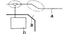
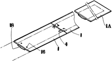
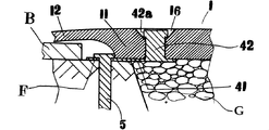
- the subject of the present invention is a temporary restoration work (first embodiment) when a long excavation groove C is excavated on the road surface B, such as a replacement work of the buried pipe A illustrated in FIG.
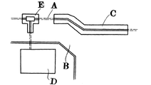
- This is intended for temporary restoration work (second embodiment) when excavating the excavation hole E for replacement / installation of branch pipes and installation of lead-in pipes to the building D.
- the road surface temporary restoration member used in the first embodiment includes a lining mat 1 (1a, 1b, 1c%), A misalignment pin 2, a retaining pin 3, and fastening bodies 4 and 4a.
- the fixing pin 5 and the ruler plate 6 (6a, 6b, 6c...) Are configured.
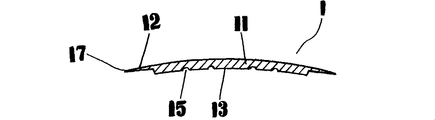
- the lining mat 1 is a rectangular rubber plate having appropriate flexibility and robustness that has been used as a conventional road surface mat, and is basically from an excavation groove B excavated in the construction of a normal buried pipe A. It is a wide and long rectangular shape, and the central thick part 11 is thickened and formed in an upwardly bulging shape across the long side ends, and the side thin parts 12 are gradually formed through steps. It is formed in a thin shape, and a concave surface 13 is formed by slightly curving upwards between the sides on the back surface (back surface of the central thick portion), and the entire direction crossing the excavation groove C bulges upward.
- the surface of the lining mat 1 is formed on the rough surface 14 with a fine protrusion, a ridge, or a narrow groove, and the concave portion 15 having a shallow semicircular cross section parallel to the side is formed on the back surface.
- a plurality of pin holes 16 are provided, and pin holes 16 penetrating the front and back are provided at appropriate places.
- the edge 17 is formed in an acute angle shape with few steps.
- a connecting protrusion 18 having a lower portion protruding is provided on one end face, and a connecting recess 19 corresponding to the connecting protrusion 18 is provided on the other end face.
- the lining mat 1 is provided with the above basic configuration, and a plurality of lining mats 1 are formed in accordance with predetermined dimensions and shapes.
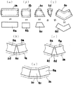
- the long lining mat 1a and the short covering are provided so as to correspond to the groove length of the excavation groove C.
- the trapezoidal lining mat 1c, the triangular lining mat 1d, and the appropriate range of the corner portion of the excavation groove C are covered.
- An arrow-type lining mat 1e having a shape is formed, and each lining mat 1 substantially coincides with each ruler plate 6 (6a, 6b, 6c, 6d) that matches the shape of the excavation groove C described later (the ruler plate).
- a central thick portion 11 having a width slightly narrower than the width direction) is provided.
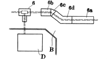
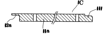
- the ruler plate 6 has, for example, a predetermined excavation groove width (two types of reference widths of 600 mm and 400 mm), a long ruler plate 6a (FIG. 8 ⁇ ) corresponding to the long lining mat 1a with an excavation groove length of 2 m.
- a short ruler plate 1b (FIG.
- a trapezoidal ruler plate 6c corresponding to 1c and the triangular lining mat 1d and an arrow type ruler plate 1d corresponding to the triangular lining mat 1d and the arrow lining mat 1e are formed (FIG. 8 ⁇ ).
- FIGS. 8 The combinations of the trapezoidal lining mat 1c, the triangular lining mat 1d, the arrow type lining mat 1e, the trapezoidal ruler plate 6c and the arrow type ruler plate 1d are as shown in FIGS. 8 ( ⁇ ), ( ⁇ ) and ( ⁇ ). is there.
- a groove end lining mat 1A having a connecting projection 18 but no connecting recess 19, or conversely a connecting recess having no connecting projection 18 is provided.
- a groove end covering mat or the like having 19 is formed in advance, and the groove end covering mat is used for the groove end portion.
- the lining mat 1 has a flat upper surface, the central thick portion 11 is formed in a bulging shape downward, and the thin side portions 12 on both sides are formed on an inclined surface only at the tip (side end) portion. But it ’s okay.
- the pin hole 16 is provided in the range of the excavation groove C, and an upper portion of the pin hole 16 is engaged with heads 21 and 31 of a later-described misalignment pin 2 and retainer pin 3 and fixing members 4 and 4a.
- the head 42a of the stop protrusion 42 is housed in an embedded state and has a shape with a sufficient exposed area.
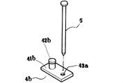
- the misalignment pin 2 is formed in a cylindrical shape, and the head portion 21 has a trumpet-shaped opening shape corresponding to the upper portion of the pin hole 16, and its entire length is inserted into the pin hole 16 of the lining mat 1.
- a length that appropriately protrudes from the bottom surface of the lining mat 1 at the time of insertion (a length sufficient to prevent the lining mat 1 from being laterally displaced with respect to a force acting on the lateral displacement received from the vehicle when the vehicle is traveling, as described later,
- the length is such that it has a length that can be easily driven into the rolled backfill soil.
- the retaining pin 3 is inserted into the cylindrical portion of the misalignment pin 2, and the head 31 fits in the head 21 of the misalignment pin 2 when being inserted, and the lower end of the misalignment pin 2. It is provided with a full length that protrudes appropriately.
- the fixing body 4 is formed by vertically projecting locking projections 42 on the upper surface of the base plate portion 41, and through holes 43 are formed at predetermined locations.
- the protruding position of the locking projection 42 is as follows. Provided so as to correspond to the distance between the pin holes 16 of the adjacent lining mat 1 in a state where the connecting projection 18 and the connecting recess 19 of the lining mat 1 are fitted in order to be connected along the excavation groove C described later. It is.
- the through hole 43 is provided at a position projecting laterally from the locking projection 42 in a range where the pavement removal portion of the road surface B when the excavation groove C is excavated and the non-excavation ground (exposed ground F).
- the fixing pin 5 has such a length as to have a strength capable of sufficiently fixing the covering mat 1 when driven into the exposed ground F from the through hole 43.
- the fastening body 4a in which the locking projections 42 are projected in a row on the upper surface of the rectangular base plate portion 41a and the through hole 43 is not provided is also provided. Can be adopted.
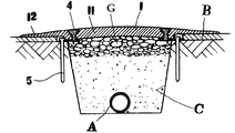
- the road surface temporary restoration method (first embodiment) according to the present invention performs the predetermined construction such as excavating the paved road surface B (excavation groove C) and replacing or installing the pipe A in the excavation groove.
- the temporary restoration member is used for temporary restoration so that the excavation groove C does not become an obstacle to vehicle travel or pedestrians at the end of a day of construction.
- the ruler plates 6 Arranged and fixed above (FIG. 2), a road surface cutter is moved in accordance with the ruler plate on the road surface, a predetermined cut is made, the pavement surface is peeled off, and the exposed ground is dug down to the buried portion of the pipe A.
- Excavation groove C is excavated within the range where road surface B is peeled, leaving non-excavation portions F on both side edges (FIG. 3), and earth and sand (usually using only sand) G in excavation groove C during temporary restoration
- the backfill portion is covered with the above-mentioned lining mat 1 and is placed in a slightly raised state according to the shape of the concave surface 13 on the back surface of the lining mat 1.
- the backfill surface is covered with the lining mat 1, and the side thin portion 12 is particularly positioned on the paved road surface B.
- the backfill surface is covered with the lining mat 1
- the ruler plates 6a, 6b, 6c used for the road surface cutter work are used.
- the lining mats 1a, 1b, 1c,... Corresponding to the shapes and dimensions are used, the backfill excavation groove C is surely covered with the lining mat 1. That is, in the temporary restoration method using the lining mat 1, the use of the ruler plate 6 makes it possible to realize complete covering in a state where there is no gap or overlap between the mats.
- the ruler plate 6 when the ruler plate 6 can be completely laid, it can be completely covered with the lining mat 1 at the time of temporary restoration. Therefore, when the excavation groove C is excavated, the combination of the ruler plates 6 is used as a lining. Determine the use of mat 1.
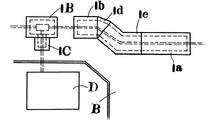
- the lining mat 1 laid so as to cover the backfill surface is integrally connected in a state where the connecting projections 18 and the connecting recesses 19 of the adjacent lining mats 1 are fitted, and the lining mat
- the fixing means 1 includes the case where the misalignment pin 2 and the retaining pin 3 are used, and the case where the fixing body 4 and the fixing pin 5 are used.
- the former is a lining mat located at the end of the backfilling place. 1 is used for fixing and other appropriate places, and the latter is used for connecting portions of adjacent lining mats 1.
- the slip retaining pin 2 When using the slip prevention pin 2 and the retaining pin 3, the slip retaining pin 2 is driven into the backfill sand G from the pin hole 16, and the backstop pin 3 is backfilled from the cylindrical inside of the slip prevention pin 2. It is driven into H and the lining mat 1 is fixed. In addition, you may make it mount
- the fastening body 4 When the fastening body 4 and the fixing pin 5 are used, the fastening body 4 is positioned on the lower surface of the adjacent lining mat 1, and each pin of the adjacent lining mat 1 is provided with the engaging protrusions 42 arranged in a row.
- the lining mat 1 attaches the fastening body 4 by inserting and fixing to the hole 16, positioning the protruding portion of the base plate portion 41 in the non-excavated portion F, and driving the fixing pin 5 through the through-hole 43. (See FIGS. 9 and 10).
- the mats adjacent to each other may be connected using the fastening body 4a.
- the excavation groove C is backfilled with earth and sand G and covered with the lining mat 1, and it is not necessary to use asphalt material for the temporary restoration. It has sufficient durability against running, and there is no need to lay a rolling element or simulated roadbed under the mat.
- the large-diameter misalignment pin 2 is driven shallowly and the small-diameter retaining pin 3 is driven deeply, so that the lining mat has sufficient strength with easy construction. 1 can be fixed.
- the adjacent lining mat 1 is coupled with the connection by the fitting of the connecting projection 18 and the connecting recess 19, and further, the covering covering adjacent by the fastening body 4 is used. Since the work mat 1 is coupled, the entire lining mat 1 can be integrated, and the lining mat 1 can be more effectively fixed.
- the edge 17 of the lining mat 1 is paved even when the central thick portion 11 is shifted to the subsidence state.
- the vehicle does not jump up from the road surface C, the vehicle traveling is not hindered, and the backfill earth and sand G does not protrude.
- the central thick portion 11 of the lining mat 1 into a bulging shape or by forming the concave strip portion 15 on the back surface of the central thick portion 11 of the lining mat 1, the lining mat of the vehicle after temporary restoration 1) Even when the backfilling earth and sand G is subjected to further rolling pressure and the backfilling earth and sand G sinks when traveling on 1, the problem derived from this settlement is solved by adopting this construction method. . Further, when it rains, the central thick portion 11 swells, so that rainwater does not stay on the lining mat 1.
- the head exposed area is correspondingly increased, so that when the vehicle weight due to vehicle travel is received, it is pressed downward together with the lining mat 1. That is, the pressure is reduced together with the central thick portion 11 of the lining mat 1 and the state is maintained, and even if the lining mat 1 sinks, it does not protrude from the upper surface.
- the mat is used particularly for temporary restoration of a sidewalk portion.
- the step of the side edge reduces the risk of pedestrians traveling and reduces the risk of slipping on the mat surface, thus realizing safe walking.
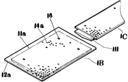
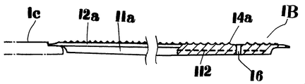
- the road surface temporary restoration member used in the temporary restoration work (second embodiment) in the piping work for forming the excavation hole E instead of the long groove on the road surface B is the lining mats 1B and 1C and the first embodiment.
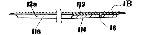
- the lining mat 1B is formed of the same material as that of the lining mat 1 described above, but is provided with side side thin portions 12a on the four sides of the central thick portion 11b through a step, on the surface. Is formed on the rough surface 14a (provided by forming small protrusions) with fine protrusions, protrusions or grooves, and the back surface is slightly bulged. Pin holes 16a penetrating front and back are provided at the four corners of 11a.
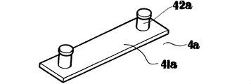
- the lining mat 1C used in connection with the lining mat 1B is provided with a side thin portion 12a similar to the lining mat 1B at the three peripheral edges, and at the peripheral edge where the side thin portions 12a are not formed.
- the continuous protrusion 111 corresponding to the lower gap shape of the side thin part 12a of the lining mat 1B is provided.
- the lining mat 1B has a two-layer structure in which a metal mesh member 112 is internally reinforced inside the central thick portion 11a, or a hard rubber material 113 is formed on the front surface side, and a soft rubber material 114 is formed on the back surface side. As mentioned above, the strength and durability are enhanced. Of course, the present invention can also be applied to the lining mats 1 and 1A of the first embodiment.
- the fastening body 4b has a locking projection 42b protruding on one side of the upper surface of the base plate portion 41b and a through hole 43a formed on the other side.
- the positional relationship between the portion 42 b and the through hole 43 a is the same as that of the locking protrusion 42 and the through hole 43 of the above-described fastening body 4.
- a rectangular excavation hole E is excavated on the paved road surface B, the earth and sand G is backfilled in the excavation hole E after predetermined construction, and the backfill portion is covered with the above-described covering.
- the excavation hole E is a single rectangular hole and covered with the work mats 1B and 1C, the backfilling portion is covered with one cover mat 1B, and the above-described misalignment pin 2 and retaining pin 3 are used.
- the lining mat 1B is fixed, or is fixed by using the fixing body 4b and the fixing pin 5, and the fixing means (driving of the pin or the like) is the same as in the first embodiment.
- the excavation hole E continuously excavates a short slot, as in the case of a lead-in pipe installed in the building D, if the above-mentioned one lining mat 1 cannot cover the backfill portion, continuous
- the lining mat 1C provided with the projecting protrusion 111 is used, the connecting protrusion 111 is positioned below the side thin portion 12a of the lining mat 1B, and the upper surface (antislip surface) is continuously flattened. In this way, the lining mats 1B and 1C are fixed. Of course, it is also possible to continuously lay the lining mat 1C.
Landscapes
- Engineering & Computer Science (AREA)
- Architecture (AREA)
- Civil Engineering (AREA)
- Structural Engineering (AREA)
- Road Paving Structures (AREA)
- Road Repair (AREA)
Priority Applications (3)
| Application Number | Priority Date | Filing Date | Title |
|---|---|---|---|
| US13/059,896 US20110142539A1 (en) | 2008-08-22 | 2009-06-22 | Member for temporarily restoring road surface and method for temporarily restoring road surface |
| KR1020117005522A KR101258417B1 (ko) | 2008-08-22 | 2009-06-22 | 노면 가복구용 부재 및 노면 가복구공법 |
| CN2009801324804A CN102131985A (zh) | 2008-08-22 | 2009-06-22 | 路面临时修复用部件以及路面临时修复施工方法 |
Applications Claiming Priority (6)
| Application Number | Priority Date | Filing Date | Title |
|---|---|---|---|
| JP2008-213511 | 2008-08-22 | ||
| JP2008213511 | 2008-08-22 | ||
| JP2008240540 | 2008-09-19 | ||
| JP2008-240540 | 2008-09-19 | ||
| JP2009-039133 | 2009-02-23 | ||
| JP2009039133A JP4931949B2 (ja) | 2008-03-18 | 2009-02-23 | 路面仮復旧用部材及び路面仮復旧工法 |
Publications (1)
| Publication Number | Publication Date |
|---|---|
| WO2010021199A1 true WO2010021199A1 (ja) | 2010-02-25 |
Family
ID=41707078
Family Applications (1)
| Application Number | Title | Priority Date | Filing Date |
|---|---|---|---|
| PCT/JP2009/061328 Ceased WO2010021199A1 (ja) | 2008-08-22 | 2009-06-22 | 路面仮復旧用部材及び路面仮復旧工法 |
Country Status (5)
| Country | Link |
|---|---|
| US (1) | US20110142539A1 (enExample) |
| JP (1) | JP4931949B2 (enExample) |
| KR (1) | KR101258417B1 (enExample) |
| CN (1) | CN102131985A (enExample) |
| WO (1) | WO2010021199A1 (enExample) |
Cited By (1)
| Publication number | Priority date | Publication date | Assignee | Title |
|---|---|---|---|---|
| GB2476873A (en) * | 2010-01-08 | 2011-07-13 | Oxford Plastic Sys Ltd | Trench Cover with retaining means |
Families Citing this family (15)
| Publication number | Priority date | Publication date | Assignee | Title |
|---|---|---|---|---|
| JP4931949B2 (ja) | 2008-03-18 | 2012-05-16 | 明和工業株式会社 | 路面仮復旧用部材及び路面仮復旧工法 |
| US20130047351A1 (en) | 2011-08-31 | 2013-02-28 | Marc Breault | Pipeline crossing bridge |
| CN102535303B (zh) * | 2012-02-16 | 2015-04-08 | 张恒亮 | 临时应急路面器材 |
| US8967904B1 (en) | 2012-10-05 | 2015-03-03 | Pioneer Detectable, LLC | Tactile plate assembly |
| KR101454709B1 (ko) * | 2012-10-08 | 2014-10-27 | 정운규 | 도로 복구용 가설패널 및 이를 이용한 도로 복구방법 |
| CN104612016B (zh) * | 2014-12-11 | 2016-06-08 | 舜元建设(集团)有限公司 | 一种快捷的市政道路抢修方法 |
| EP3342007B1 (en) * | 2015-08-27 | 2023-06-07 | Newpark Mats & Integrated Services LLC | Apparatus and methods for electrically grounding at least one mat in a load-supporting surface |
| CN105970785B (zh) * | 2016-06-07 | 2018-01-09 | 中国南方航空工业(集团)有限公司 | 混凝土路面深坑快速修理设备及方法 |
| US10744360B2 (en) * | 2017-04-04 | 2020-08-18 | Polymer Technologies, Inc. | Energy dissipative floor mat, mat system, and manufacturing process |
| CA2965450C (en) * | 2017-04-27 | 2021-10-12 | Busby Enterprises Ltd | System, apparatus and related method for raised ground cover mat |
| FR3095660B1 (fr) * | 2019-04-30 | 2021-06-04 | Filippo Cunsolo | DISPOSITIF de revêtement de surface |
| CN111472226A (zh) * | 2020-04-29 | 2020-07-31 | 无锡市政设计研究院有限公司 | 一种非牛顿流体枕袋及使用其进行路面临时修复的方法 |
| CN113174803A (zh) * | 2021-04-27 | 2021-07-27 | 重庆育才工程咨询监理有限公司 | 高速公路路面修复用导流装置及路面修复方法 |
| ES3034444T3 (en) * | 2021-07-23 | 2025-08-18 | Matpro Services Corp | Method of repairing a mat and repaired mat |
| JP7698509B2 (ja) * | 2021-08-06 | 2025-06-25 | 株式会社大林組 | 舗装構造及び、舗装方法 |
Citations (3)
| Publication number | Priority date | Publication date | Assignee | Title |
|---|---|---|---|---|
| JPS58145305U (ja) * | 1982-03-26 | 1983-09-30 | 産興商事株式会社 | 仮復旧用マツト |
| JPH057708U (ja) * | 1991-07-12 | 1993-02-02 | 株式会社イノアツクコーポレーシヨン | 歩道用仮蓋 |
| JP2005264693A (ja) * | 2004-03-15 | 2005-09-29 | Inb Planning:Kk | 曲げ変形のないゴム製仮舗材とその製造方法 |
Family Cites Families (11)
| Publication number | Priority date | Publication date | Assignee | Title |
|---|---|---|---|---|
| US2358426A (en) * | 1942-06-17 | 1944-09-19 | John W Tompson | Safety landing field for airplanes |
| US3930100A (en) * | 1966-10-21 | 1975-12-30 | Charles H Mcdonald | Elastomeric cold patch for pavement repair |
| US4067155A (en) * | 1975-08-28 | 1978-01-10 | Grefco, Inc. | Sealing system |
| US4129967A (en) * | 1977-06-10 | 1978-12-19 | John D. VanWagoner | Apparatus for collecting fluid seepage in a building structure |
| JPS58145305A (ja) * | 1982-02-22 | 1983-08-30 | Mitsubishi Electric Corp | 同期装置 |
| US4445640A (en) * | 1982-03-31 | 1984-05-01 | The Goodyear Tire & Rubber Company | Highway railway crossing and cap therefor |
| US4746243A (en) * | 1986-05-29 | 1988-05-24 | Eagle-Picher Industries, Inc. | Apparatus and method for rapid repair of damaged airfield runways |
| US5660498A (en) * | 1996-01-16 | 1997-08-26 | Freeman; Roger | Patching system and method for repairing roadways |
| GB2370063B (en) * | 1999-09-17 | 2004-01-14 | David Vincent Byrne | A trench cover element |
| US6520714B1 (en) * | 2001-08-09 | 2003-02-18 | Jerrold L. Marsik, Jr. | Transition surface for roadway |
| JP4931949B2 (ja) | 2008-03-18 | 2012-05-16 | 明和工業株式会社 | 路面仮復旧用部材及び路面仮復旧工法 |
-
2009
- 2009-02-23 JP JP2009039133A patent/JP4931949B2/ja not_active Expired - Fee Related
- 2009-06-22 CN CN2009801324804A patent/CN102131985A/zh active Pending
- 2009-06-22 KR KR1020117005522A patent/KR101258417B1/ko not_active Expired - Fee Related
- 2009-06-22 WO PCT/JP2009/061328 patent/WO2010021199A1/ja not_active Ceased
- 2009-06-22 US US13/059,896 patent/US20110142539A1/en not_active Abandoned
Patent Citations (3)
| Publication number | Priority date | Publication date | Assignee | Title |
|---|---|---|---|---|
| JPS58145305U (ja) * | 1982-03-26 | 1983-09-30 | 産興商事株式会社 | 仮復旧用マツト |
| JPH057708U (ja) * | 1991-07-12 | 1993-02-02 | 株式会社イノアツクコーポレーシヨン | 歩道用仮蓋 |
| JP2005264693A (ja) * | 2004-03-15 | 2005-09-29 | Inb Planning:Kk | 曲げ変形のないゴム製仮舗材とその製造方法 |
Cited By (2)
| Publication number | Priority date | Publication date | Assignee | Title |
|---|---|---|---|---|
| GB2476873A (en) * | 2010-01-08 | 2011-07-13 | Oxford Plastic Sys Ltd | Trench Cover with retaining means |
| US8956073B2 (en) | 2010-01-08 | 2015-02-17 | Oxford Plastic Systems Limited | Trench cover |
Also Published As
| Publication number | Publication date |
|---|---|
| JP4931949B2 (ja) | 2012-05-16 |
| KR101258417B1 (ko) | 2013-04-26 |
| JP2010095987A (ja) | 2010-04-30 |
| US20110142539A1 (en) | 2011-06-16 |
| CN102131985A (zh) | 2011-07-20 |
| KR20110052701A (ko) | 2011-05-18 |
Similar Documents
| Publication | Publication Date | Title |
|---|---|---|
| JP4931949B2 (ja) | 路面仮復旧用部材及び路面仮復旧工法 | |
| JP5514846B2 (ja) | 簡易覆工板 | |
| CN102575439B (zh) | 道路修复块体 | |
| KR101912770B1 (ko) | 스프링판재를 이용한 강지보재 임시고정장치 | |
| JP3131502U (ja) | 覆工作業用山留板 | |
| JP6159295B2 (ja) | マンホール補修方法 | |
| KR101205553B1 (ko) | 도로 가포장용 재생고무매트 | |
| JP4767191B2 (ja) | 山留部材及びこれを備えた路面覆工構造並びに路面覆工方法 | |
| JP4981551B2 (ja) | 壁構造物及びその構築方法 | |
| JP6095840B1 (ja) | 排水枡及びu形側溝並びに施工方法 | |
| KR200272128Y1 (ko) | 높이조절용 맨홀 | |
| KR101153717B1 (ko) | 다웰바를 구비하고 배수홈을 갖는 프리캐스트 콘크리트 받침슬래브를 이용한 콘크리트 슬래브의 이음구조 및 이를 이용한 콘크리트 슬래브 이음시공방법 | |
| JP3120150B1 (ja) | 路面覆工方法 | |
| KR101967402B1 (ko) | 기초 구조물 및 이의 시공방법 | |
| JP2019167723A (ja) | 縁石一体型の鋼製排水溝 | |
| JP2004232285A (ja) | 連続壁の防水装置及び防水方法 | |
| JP3450294B2 (ja) | 覆工板の支持構造及び覆工方法 | |
| KR200396174Y1 (ko) | 설치 및 해체가 용이한 강재 토류판 | |
| KR102895402B1 (ko) | 외방수 흙막이판을 이용한 지하구조물 시공방법 | |
| JP3112511U (ja) | 道路仮復旧用敷設ブロックマット | |
| KR102802858B1 (ko) | 우수 저류성이 향상되고 다변형이 가능한 측구 저류관로 | |
| KR100698885B1 (ko) | 경사면 하수관의 미끄럼 방지 시설 구조 | |
| KR20060034521A (ko) | 파형강판을 이용한 암거 | |
| JP3074307U (ja) | 側溝用ブロック | |
| KR200411568Y1 (ko) | 복합 기능을 갖는 맨홀 시스템 |
Legal Events
| Date | Code | Title | Description |
|---|---|---|---|
| WWE | Wipo information: entry into national phase |
Ref document number: 200980132480.4 Country of ref document: CN |
|
| 121 | Ep: the epo has been informed by wipo that ep was designated in this application |
Ref document number: 09808135 Country of ref document: EP Kind code of ref document: A1 |
|
| DPE2 | Request for preliminary examination filed before expiration of 19th month from priority date (pct application filed from 20040101) | ||
| WWE | Wipo information: entry into national phase |
Ref document number: 13059896 Country of ref document: US |
|
| NENP | Non-entry into the national phase |
Ref country code: DE |
|
| ENP | Entry into the national phase |
Ref document number: 20117005522 Country of ref document: KR Kind code of ref document: A |
|
| 122 | Ep: pct application non-entry in european phase |
Ref document number: 09808135 Country of ref document: EP Kind code of ref document: A1 |