WO2010016264A1 - 情報記録媒体および情報記録装置 - Google Patents
情報記録媒体および情報記録装置 Download PDFInfo
- Publication number
- WO2010016264A1 WO2010016264A1 PCT/JP2009/003782 JP2009003782W WO2010016264A1 WO 2010016264 A1 WO2010016264 A1 WO 2010016264A1 JP 2009003782 W JP2009003782 W JP 2009003782W WO 2010016264 A1 WO2010016264 A1 WO 2010016264A1
- Authority
- WO
- WIPO (PCT)
- Prior art keywords
- information recording
- recording
- test
- area
- information
- Prior art date
Links
Images


Classifications
-
- G—PHYSICS
- G11—INFORMATION STORAGE
- G11B—INFORMATION STORAGE BASED ON RELATIVE MOVEMENT BETWEEN RECORD CARRIER AND TRANSDUCER
- G11B7/00—Recording or reproducing by optical means, e.g. recording using a thermal beam of optical radiation by modifying optical properties or the physical structure, reproducing using an optical beam at lower power by sensing optical properties; Record carriers therefor
- G11B7/007—Arrangement of the information on the record carrier, e.g. form of tracks, actual track shape, e.g. wobbled, or cross-section, e.g. v-shaped; Sequential information structures, e.g. sectoring or header formats within a track
- G11B7/00736—Auxiliary data, e.g. lead-in, lead-out, Power Calibration Area [PCA], Burst Cutting Area [BCA], control information
-
- G—PHYSICS
- G11—INFORMATION STORAGE
- G11B—INFORMATION STORAGE BASED ON RELATIVE MOVEMENT BETWEEN RECORD CARRIER AND TRANSDUCER
- G11B7/00—Recording or reproducing by optical means, e.g. recording using a thermal beam of optical radiation by modifying optical properties or the physical structure, reproducing using an optical beam at lower power by sensing optical properties; Record carriers therefor
- G11B7/004—Recording, reproducing or erasing methods; Read, write or erase circuits therefor
- G11B7/0045—Recording
-
- G—PHYSICS
- G11—INFORMATION STORAGE
- G11B—INFORMATION STORAGE BASED ON RELATIVE MOVEMENT BETWEEN RECORD CARRIER AND TRANSDUCER
- G11B7/00—Recording or reproducing by optical means, e.g. recording using a thermal beam of optical radiation by modifying optical properties or the physical structure, reproducing using an optical beam at lower power by sensing optical properties; Record carriers therefor
- G11B7/004—Recording, reproducing or erasing methods; Read, write or erase circuits therefor
- G11B7/005—Reproducing
-
- G—PHYSICS
- G11—INFORMATION STORAGE
- G11B—INFORMATION STORAGE BASED ON RELATIVE MOVEMENT BETWEEN RECORD CARRIER AND TRANSDUCER
- G11B7/00—Recording or reproducing by optical means, e.g. recording using a thermal beam of optical radiation by modifying optical properties or the physical structure, reproducing using an optical beam at lower power by sensing optical properties; Record carriers therefor
- G11B7/12—Heads, e.g. forming of the optical beam spot or modulation of the optical beam
- G11B7/125—Optical beam sources therefor, e.g. laser control circuitry specially adapted for optical storage devices; Modulators, e.g. means for controlling the size or intensity of optical spots or optical traces
- G11B7/126—Circuits, methods or arrangements for laser control or stabilisation
- G11B7/1263—Power control during transducing, e.g. by monitoring
-
- G—PHYSICS
- G11—INFORMATION STORAGE
- G11B—INFORMATION STORAGE BASED ON RELATIVE MOVEMENT BETWEEN RECORD CARRIER AND TRANSDUCER
- G11B7/00—Recording or reproducing by optical means, e.g. recording using a thermal beam of optical radiation by modifying optical properties or the physical structure, reproducing using an optical beam at lower power by sensing optical properties; Record carriers therefor
- G11B7/12—Heads, e.g. forming of the optical beam spot or modulation of the optical beam
- G11B7/125—Optical beam sources therefor, e.g. laser control circuitry specially adapted for optical storage devices; Modulators, e.g. means for controlling the size or intensity of optical spots or optical traces
- G11B7/126—Circuits, methods or arrangements for laser control or stabilisation
- G11B7/1267—Power calibration
-
- G—PHYSICS
- G11—INFORMATION STORAGE
- G11B—INFORMATION STORAGE BASED ON RELATIVE MOVEMENT BETWEEN RECORD CARRIER AND TRANSDUCER
- G11B7/00—Recording or reproducing by optical means, e.g. recording using a thermal beam of optical radiation by modifying optical properties or the physical structure, reproducing using an optical beam at lower power by sensing optical properties; Record carriers therefor
- G11B7/12—Heads, e.g. forming of the optical beam spot or modulation of the optical beam
- G11B7/135—Means for guiding the beam from the source to the record carrier or from the record carrier to the detector
- G11B7/1392—Means for controlling the beam wavefront, e.g. for correction of aberration
- G11B7/13925—Means for controlling the beam wavefront, e.g. for correction of aberration active, e.g. controlled by electrical or mechanical means
-
- G—PHYSICS
- G11—INFORMATION STORAGE
- G11B—INFORMATION STORAGE BASED ON RELATIVE MOVEMENT BETWEEN RECORD CARRIER AND TRANSDUCER
- G11B7/00—Recording or reproducing by optical means, e.g. recording using a thermal beam of optical radiation by modifying optical properties or the physical structure, reproducing using an optical beam at lower power by sensing optical properties; Record carriers therefor
- G11B7/24—Record carriers characterised by shape, structure or physical properties, or by the selection of the material
- G11B7/2403—Layers; Shape, structure or physical properties thereof
- G11B7/24035—Recording layers
- G11B7/24038—Multiple laminated recording layers
Definitions
- the present invention relates to an information recording medium for recording information by irradiating a laser beam, and more particularly to an information recording medium having three or more information recording layers and an information recording apparatus suitable for the information recording medium.
- an information recording medium capable of recording information by irradiating light modulated by information to be recorded, for example, laser light.
- Such information recording media include a write-once type information recording medium capable of recording information only once in one place and a rewritable type information recording medium capable of rewriting information many times. These are called a write once optical disc and a rewritable optical disc, respectively.
- Such an optical disc is provided with a test recording area for determining an appropriate recording condition for recording information, particularly a light recording power, in each information recording layer.
- the recording power is optimized by using a test recording area when the device is started or immediately before recording.
- Patent Document 1 discloses a method for determining recording power in a write-once optical disc.
- Patent Document 1 discloses a technique related to an optical disc having two information recording layers. However, a structure relating to an optical disc provided with three or more information recording layers, in particular, the arrangement of test recording areas and the method of using the same are not disclosed.
- the present invention solves such a problem of the prior art, includes an information recording medium that includes three or more information recording layers, and can record information under appropriate conditions in each information recording layer, and such An object of the present invention is to provide an information recording apparatus suitable for an information recording medium.
- the information recording medium of the present invention is an information recording medium capable of recording data with a laser beam and having n layers (n is an integer of 3 or more) of information recording layers stacked on each other.
- Each of the information recording layers has a test recording area for determining the recording power of the laser beam, and when the n information recording layers are counted from the side farthest from the incident surface of the laser beam, the i th ( i is an integer satisfying 2 ⁇ i ⁇ n ⁇ 1) of the test recording area of the information recording layer and the test recording area of the (i + 1) th information recording layer Of the information recording layer of the j-th (j is an integer satisfying 1 ⁇ j ⁇ i ⁇ 1).
- Test recording in test recording area and j + 1th information recording layer Of range greater than radial gap between the radial position of the inner peripheral edge portion of the inner peripheral side arranged test recording area test recording area disposed on the radial position and the outer peripheral side of the outer peripheral edge of the.
- Another information recording medium of the present invention has at least three information recording layers, and each pair is formed on a pair of adjacent information recording layers located on the side relatively closer to the laser light incident surface.
- the radial distance between the test recording areas is a radius between a pair of test recording areas formed on a pair of adjacent information recording layers, which are positioned relatively far from the laser light incident surface. Greater than the spacing in the direction.
- Another information recording medium of the present invention is an information recording medium capable of recording data with a laser beam and having n information recording layers (n is an integer of 3 or more) stacked on each other.
- Each of the information recording layers has a test recording area for determining the recording power of the laser beam, and when the n information recording layers are counted from the side farthest from the incident surface of the laser beam, k Of the test recording areas arranged on the inner circumference side of the test recording area of the information recording layer (k is an integer satisfying 1 ⁇ k ⁇ n ⁇ 2) and the test recording area of the (k + 1) th information recording layer
- the radial position difference between the radial position of the peripheral edge and the radial position of the outer peripheral edge of the test recording area arranged on the outer peripheral side is the test recording area of the kth information recording layer and the test recording of the k + 2th information recording layer. It is arranged on the inner circumference side of the area Greater than radial gap between the radial position of the outer peripheral edge
- n 4 and k is 1.
- Another information recording medium of the present invention is an information recording medium capable of recording data with a laser beam and having n layers (n is an integer of 4 or more) stacked on each other, wherein the n
- Each of the information recording layers has a test recording area for determining the recording power of the laser beam, and when the n information recording layers are counted from the side farthest from the incident surface of the laser beam, k Of the test recording area of the information recording layer (k ′ is an integer satisfying 1 ⁇ k ′ ⁇ n ⁇ 3) and the test recording area of the k ′ + 1th information recording layer, the test arranged on the inner circumference side
- the radial position difference between the radial position of the inner peripheral edge of the recording area and the radial position of the outer peripheral edge of the test recording area arranged on the outer peripheral side is the test recording area of the k ′ + 1th information recording layer and k ′ + 3.
- the test recording area of the second information recording layer Greater than radial gap between the radial
- Another information recording medium of the present invention is an information recording medium capable of recording data with a laser beam and having n information recording layers (n is an integer of 3 or more) stacked on each other.
- Each of the information recording layers has a test recording area for determining the recording power of the laser beam, and when the n information recording layers are counted from the side farthest from the incident surface of the laser beam, 3
- the test recording area of the first information recording layer is positioned on the outer peripheral side from the test recording area of the first information recording layer, and the test recording area of the first information recording layer is the second information recording layer It is located on the outer peripheral side of the test recording area.
- n 4.
- Another information recording medium of the present invention is an information recording medium capable of recording data with a laser beam and having n layers (n is an integer of 4 or more) stacked on each other, wherein the n
- Each of the information recording layers has a test recording area for determining the recording power of the laser beam, and when the n information recording layers are counted from the side farthest from the incident surface of the laser beam, 3
- the test recording area of the second information recording layer is located on the outer peripheral side of the test recording area of the second information recording layer, and the test recording area of the second information recording layer is the fourth information recording layer It is located on the outer peripheral side of the test recording area.
- Another information recording medium of the present invention is an information recording medium capable of recording data with a laser beam and having n layers (n is an integer of 4 or more) stacked on each other, wherein the n
- Each of the information recording layers has a test recording area for determining the recording power of the laser beam, and when the n information recording layers are counted from the side farthest from the incident surface of the laser beam, 3
- the test recording area of the first information recording layer is positioned on the outer peripheral side from the test recording area of the first information recording layer, and the test recording area of the first information recording layer is the fourth information recording layer It is located on the outer peripheral side of the test recording area.
- Another information recording medium of the present invention is an information recording medium capable of recording data with a laser beam and having n information recording layers (n is an integer of 3 or more) stacked on each other.
- Each of the information recording layers has test recording areas provided at different radial positions for determining the recording power of the laser beam, and a plurality of sub areas are provided in the test recording area.
- the laser beam is on the outer peripheral side. From the inner circumference side to the outer circumference side, and in the test recording area, the sub-area is used from the inner circumference side to the outer circumference side.
- the test record is scanned towards the side In-band, the sub-region are used toward the inner edge.
- the information reproducing apparatus of the present invention is an information reproducing apparatus for reproducing any one of the above information recording media, wherein the information recording medium is controlled to at least one information recording layer of the n information recording layers.
- An information recording apparatus is an information recording apparatus for recording any one of the above-described information recording media, wherein a test recording area of any one of the n information recording layers is used to transmit laser light. A recording power is determined, the laser beam is irradiated with the determined recording power, and data is recorded on any one of the layers.
- the reproducing method of the present invention is a reproducing method for reproducing any one of the information recording media described above, wherein the information recording medium has a control area in at least one information recording layer of the n information recording layers. And reproducing information related to the information recording medium from the control area, and recording on one of the n information recording layers with a recording power adjusted using the test recording area of the layer At least one of the steps of reproducing the recorded data.
- the recording method of the present invention is a recording method for recording data on any of the information recording media described above, and recording laser light using a test recording area of any one of the n information recording layers.
- a test recording area is provided in each information recording layer. Therefore, even if the information recording layer is laminated, even if the irradiation intensity of the laser beam, the thermal environment, etc. are different for each information recording layer, the test recording area of the information recording layer to be recorded is used. Test recording can be performed in the environment of the information recording layer. Therefore, the optimum recording power for each information recording layer can be determined.
- FIG. 1 is a schematic exploded perspective view showing a configuration of a first embodiment of an information recording medium according to the present invention. It is a schematic diagram which shows arrangement
- (A) is a figure which shows typically the structure of each information recording layer of the information recording medium of FIG. 1, (b) and (c) are schematic diagrams which respectively show the use direction of a test recording area.
- (b) is a schematic diagram which shows other arrangement
- (A) And (b) is a schematic diagram which respectively shows the spot recorded on the track
- the information recording medium according to the present invention is a write-once type or a rewritable type.
- FIG. 1 is a schematic exploded perspective view showing a configuration of a first embodiment of an information recording medium according to the present invention.
- an information recording medium capable of optically recording information and optically reproducing the recorded information is generally referred to as an optical disk. Therefore, hereinafter, the information recording medium is referred to as an optical disk.
- “Information” means character information, audio information, image information, programs, and other various information recorded on the information recording medium. These pieces of information are digitized and recorded on an information recording medium or processed by various information processing apparatuses.
- “information” processed by a computer is defined as “data”, “information” is synonymous with “data” in the present specification.
- the term “information” or “data” is selectively used in accordance with general or conventional expressions.
- an optical disc or the like is generally called an “information recording medium”, but an area for recording information is called a “data area”.
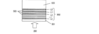
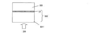
- the optical disc 101 includes a substrate 110, information recording layers L0, L1, and L2, intermediate layers 111 and 112, and a cover layer 113.
- Information recording layers L0, L1, and L2 are disposed between the substrate 110 and the cover layer 113, the information recording layer L0 is disposed on the substrate 110 side, and the information recording layer L2 is disposed on the cover layer 113 side. Since the laser beam 200 modulated by the information to be recorded is irradiated from the cover layer 113 side, the information recording layers L0, L1, and L2 are arranged in this order from the side far from the surface of the cover layer 113 that is the incident surface of the laser beam 200. It is arranged with.
- the intermediate layer 111 and the intermediate layer 112 are provided between the information recording layer L0 and the information recording layer L1, and between the information recording layer L1 and the information recording layer L2, respectively.
- the substrate 110, the information recording layers L0, L1, and L2, the intermediate layers 111 and 112, and the cover layer 113 are laminated in the above-described arrangement and bonded to each other, and a clamp hole 114 is provided at the center of the optical disc 101 that is constituted by the lamination. It has been.
- the substrate 110, the intermediate layers 111 and 112, and the cover layer 113 are made of, for example, polycarbonate resin.
- Each of the information recording layers L0, L1, and L2 is provided with a track for recording data provided concentrically or spirally.
- the information recording layers L0, L1, and L2 are provided with data areas D0, D1, and D2, and lead-in areas R0, R1, and R2 provided on the inner peripheral side of the data areas D0, D1, and D2, respectively. It has been.
- Data areas D0, D1, and D2 are areas for recording user data.
- the optical disc 101 When the optical disc 101 is a write-once type, information can be recorded only once in the same location in the data areas D0, D1, and D2. The recorded information cannot be rewritten.
- the optical disc 101 When the optical disc 101 is a rewritable type, information can be recorded in the data areas D0, D1, and D2, and the recorded information can be rewritten with other information.
- Each of the lead-in areas R0, R1, and R2 includes at least a control area (also called a PIC (Permanent Information & Control Data) area) which is a reproduction-only area and a test recording area (OPC (Optimum Power Control) capable of recording information). Also referred to as a region).
- a control area also called a PIC (Permanent Information & Control Data) area
- OPC Optimum Power Control
- the test recording area is used to adjust the recording power of the laser beam used when recording information in the data area. Specifically, a recording mark is formed by irradiating the test recording area with a laser beam modulated by predetermined information while changing the recording power. Thereafter, the formed recording mark is irradiated with laser light, the recorded information is reproduced, and the quality of the reproduced information is evaluated to determine the optimum recording power.
- test recording area of the lead-in area R0 is used for adjusting the recording power of the laser beam for recording information in the data area D0 of the same information recording layer L0.
- test recording areas of the lead-in areas R1 and R2 are used to adjust the recording power of the laser beam that records information in the data areas D1 and D2, respectively.
- recording parameter information such as disc information and irradiation power at the time of user data recording recommended by a media (optical disc) manufacturer is recorded (stored).
- the optimum recording parameters for recording information on each information recording layer L0, L1, and L3 are different for each information recording layer.
- information is stored in other information recording layers. Recording parameter information for recording is recorded. Specifically, recording parameter information for recording information in the data areas D0, D1, and D2 of the information recording layers L0, L1, and L2 is recorded in the control area of the lead-in area R0. Similarly, recording parameter information for recording information in the data areas D0, D1, and D2 of the information recording layers L0, L1, and L2 is also recorded in the control areas of the lead-in areas R1 and R2.
- the recording parameter information of all information recording layers can be obtained from the control area of any one information recording layer. For this reason, it is possible to shorten the time until user data is recorded, compared to the case where only the recording parameter information for the information recording layer is recorded in the control area of each information recording layer. Even if the reproduction of an erroneous information recording layer different from the desired information recording layer is started due to disturbance or the like, the intended information recording layer is reproduced by reproducing the control area of the erroneous information recording layer. Recording parameter information can be obtained.
- the recording method of recording parameters in the control area is not limited to this. Only the recording parameter information for recording in the data area of the information recording layer may be recorded in the control area of each information recording layer. In this case, since the capacity of the recording parameter information to be recorded in each control area is reduced, the control area can be reduced. Therefore, as will be described below, the number of information recording layers increases, and it becomes easy to secure the control area even when the radial positions of the test recording areas of the respective layers are different.
- recording parameter information for recording information in the data areas of all the information recording layers included in the optical disc 101 is recorded in the control area of any one information recording layer. It may be.
- the control area in which the recording parameter information of all the information recording layers is recorded may be arranged in the information recording layer farthest from the light incident surface.
- the recording parameter information for recording information in the data areas D0, D1, and D2 of the information recording layers L0, L1, and L2 is the lead-in area R0 of the information recording layer L0. It may be recorded only in the control area provided in.
- the depth (thickness) from the incident surface (the surface of the disk 101) to the information recording layer L0 from the incident surface (the surface of the disk 101) of the cover layer 113 is from the surface of the disk in the optical disk having one information recording layer. It may coincide with the depth to the information recording layer. Accordingly, it is possible to obtain the disc information of any information recording layer of the information recording layers L0, L1, and L2 of the optical disc 101 using an optical disc apparatus that performs recording and reproduction with respect to an optical disc having one information recording layer. Thus, the configuration of the optical disk apparatus can be simplified.
- the depth from the surface to the information recording layer (reference layer) located closest to the substrate is from the surface of the disc in the optical disc having one information recording layer.
- the depth is preferably equal to the depth to the information recording layer.
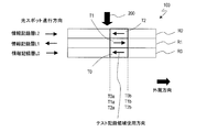
- FIG. 2 is a schematic cross-sectional view of the optical disc 101 and shows the arrangement of the test recording areas in the lead-in areas R0, R1, and R2.
- the intermediate layers 111 and 112 are not shown.
- the laser beam 200 is irradiated from above in FIG. 2, and the outer circumferential direction of the disk is on the right side as indicated by an arrow.
- test recording areas T0, T1, and T2 are located in the lead-in areas R0, R1, and R2 of the information recording layers L0, L1, and L2, respectively.
- the test recording areas T0, T1, and T2 are arranged at different radial positions, and do not overlap each other when viewed from the stacking direction of the information recording layers L0, L1, and L2, that is, the incident direction of the laser beam 200.
- the test of the information recording layer L0 disposed on the inner peripheral side second from the outer peripheral end T1b of the test recording region T1 of the information recording layer L1 disposed on the innermost peripheral side is performed.
- the inner peripheral end T0a of the recording area T0 is located on the outer peripheral side, and a gap (interval) is provided so that the test recording areas do not overlap.
- This gap has a distance defined by the difference between the radial position of the inner peripheral end T0a and the radial position of the outer peripheral end T1b.
- the test recording area T2 of the information recording layer L2 that is the third information recording layer is the first layer.
- the test recording area T0 of the information recording layer L0 is located on the outer peripheral side of the test recording area T0 of the information recording layer L0 that is the information recording layer, and the test recording area T1 of the information recording layer L1 that is the second information recording layer. Located on the outer periphery.
- test recording areas T0, T1, and T2 are arranged at the same radial position in the information recording layers L0, L1, and L2, respectively.
- the radial positions of the inner peripheral end T0a of the test recording area T0, the inner peripheral end T1a of the test recording area T1, and the inner peripheral end T2a of the test recording area T2 coincide with each other, and the outer peripheral end T0b of the test recording area T0.
- test recording areas T0, T1, and T2 are completely overlapped with each other because the radial positions of the outer peripheral end T1b of the test recording area T1 and the outer peripheral end T2b of the test recording area T2 coincide with each other.
- the transmittance of the laser light in the test recording area T1 is greatly reduced, so that the information recording layer located farther from the laser light than the information recording layer L1.
- the laser beam cannot reach the test recording area T0 of L0 correctly.
- the optical disk apparatus that performs test recording cannot access the test recording area T0 of the information recording layer L0.
- the transmittance of the test recording area T1 is changed by performing the test recording with a high irradiation power on the test recording area T1 of the information recording layer L1 even before destruction, the recording in the test recording area T1 is performed.
- the intensity of the laser beam reaching the information recording layer L0 changes depending on the presence or absence.
- test recording area T2 If the test recording area T2 is destroyed or the laser light transmittance in the test recording area T2 changes, the test recording areas T0 and T1 may be affected. Therefore, the test recording areas shown in FIG. 3 cannot correctly perform test recording using the test recording areas T0 and T1 of the information recording layers L0 and L1, so that the recording power of the information recording layers L0 and L1 is set correctly. It may not be possible to decide.
- the radial positions of the test recording areas T0, T1, and T2 are different, and the test recording areas T0, T1, and T2 are the information recording layers. It does not overlap in the stacking direction. For this reason, even if the test recording area T1 of the information recording layer L1 is destroyed, the laser beam is applied to the test recording area T0 of the information recording layer L0 without being influenced or hardly affected by the destroyed test recording area T1. Will arrive correctly. Therefore, the test recording can be correctly performed using the test recording area T0 of the information recording layer L0, and the recording power of the information recording layer L0 can be correctly determined. Similarly, even if the test recording area T2 of the information recording layer L2 is destroyed, the recording power of the information recording layers L0 and L1 can be correctly determined.
- the laser light correctly reaches the test recording areas T0, T1, and T2 of the information recording layers L0, L1, and L2. . Therefore, it is possible to correctly perform test recording using the test recording areas T0, T1, and T2 of the information recording layers L0, L1, and L2, and to correctly determine the recording power of the information recording layers L0, L1, and L2.
- the recording mark in the amorphous state and the recording mark in the crystalline state may differ, the recording mark may be changed after the recording power is determined. By erasing, it is possible not to change the transmittance of the information recording layer.
- the recording film characteristics of the information recording layer are irreversible. Therefore, the arrangement of the test recording area of the present embodiment is particularly useful for a write-once optical disc.
- tracks are configured so that laser light scans the information recording layers L0 and L2 from the inner periphery toward the outer periphery.
- the track is configured so that the laser beam scans the information recording layer L1 from the outer periphery toward the inner periphery.
- the direction of the spiral of the track is reversed between the information recording layers L0 and L2 and the information recording layer L1.
- the same radius is applied after the last recording or reproduction on the information recording layer L0 is performed at the outermost peripheral position of the data area D0.
- the first recording or reproduction in the information recording layer L1 can be started from the outermost peripheral position of the data area D1 while maintaining the laser beam at the position.
- the first recording or reproduction in the information recording layer L2 is performed in the data area while maintaining the laser beam at the same radial position. It can start from the innermost circumferential position of D2.
- the traveling direction of the light spot of the laser beam in each layer is not limited to this as long as requirements described later are satisfied.
- test recording areas T0, T1, and T2 are preferably used in a direction opposite to the traveling direction of the light spot of the laser beam in each information recording layer.
- the use direction of the test recording area will be described.
- the test recording area provided in each information recording layer is a test recording area used to determine the irradiation power of laser light when data is recorded in the data area of the information recording layer. is there.
- the test data is recorded while increasing the irradiation power by 1 mW, the area where the test recording was performed is reproduced after recording, and the irradiation power with the best reproduction index such as the error rate and jitter of the reproduction signal is determined.
- the irradiation power for recording the test data may be determined in the vicinity of the recommended irradiation power recorded in the control area with reference to the control area, for example. However, if it is estimated that there is a deviation between the set power and the actual irradiation power due to variations in the sensitivity of the optical disk to the laser light and variations in the performance of the optical head of the optical disk device that records on the optical disk, etc. May be considered. In this case, the test data may be recorded while changing the irradiation power by 5%, for example, within a power range of about ⁇ 20% of the recommended power.
- an irradiation power other than the irradiation power that gives the best reproduction index may be determined.
- a reference value may be set for the error rate, jitter, etc., and the power near the center of the irradiation power range that is less than or equal to the reference value may be determined as the recording power for recording user data.
- the variation is less than the reference value. Good recording quality can be maintained within the power range. Even when the optical disc is warped, good recording quality can be maintained as long as the fluctuation of the recording power due to the warpage is within the irradiation power range where it is below the reference value.
- the rewritable optical disc can perform test recording multiple times in the same area. For this reason, it is not necessary to provide any particular restriction on the method of using the test recording area.
- the recordable optical disc that can record data only once since the test data is recorded with a plurality of irradiation powers in determining the recording power, the unrecorded area of the test recording area is randomly selected. It is more efficient to use them sequentially from the end than to use them (worm-eating). Even in the rewritable optical disk, when the recording performance changes with repeated recording, it is desirable to use the test recording areas in order from the end as in the write-once optical disk.
- FIG. 4A shows an arbitrary information recording layer Ln (n is 0, 1, or 2) among the information recording layers L0, L1, and L2 of the optical disc 101.
- the information recording layer Ln is provided with the lead-in area Rn
- the test recording area Tn is provided in the lead-in area Rn. Addresses are also given to the test recording areas T0, T1, and T2, and each test recording area includes a sub-area called a cluster, which is an area where a predetermined number of addresses are continuous.
- 4B and 4C schematically show the sub areas t1, t2, t3, t4, t5,... Of the test recording area Tn. For example, one sub area is used by one test recording described above.
- the number of sub-areas (clusters) constituting the test recording areas T0, T1, and T2 of the information recording layers L0, L1, and L2 is equal to each other. That is, the test recording areas T0, T1, and T2 are equal in size.
- the sub area of the test recording area T0 includes a plurality of sub areas t1, t2, t3, t4 to which addresses are assigned according to the scanning direction of the laser beam indicated by the arrow. t5,... exist.
- the plurality of sub-regions t1, t2, t3, t4, t5,... are used from the outer periphery toward the inner periphery. That is, the unused sub-areas t1, t2, t3, t4, t5,.
- FIG.4 (b) it uses in order of t5, t4, t3, t2, t1.
- test recording is performed in each sub-region according to the scanning direction of the laser beam as indicated by an arrow.
- the laser beam scans the information recording layer L2 from the inner periphery toward the outer periphery. Therefore, the plurality of sub-regions t1, t2, t3, t4, t5,... Are used in the order of t5, t4, t3, t2, t1 from the outer periphery toward the inner periphery.
- the sub area of the test recording area T1 includes a plurality of sub areas t1, t2, t3, t4 to which addresses are assigned according to the scanning direction of the laser beam indicated by the arrow. t5,... exist.
- a plurality of subregions t1, t2, t3, t4, t5,... Are used from the inner periphery toward the outer periphery. That is, the unused subregions t1, t2, t3, t4, t5,... Are used in the order of t5, t4, t3, t2, t1 from the innermost side.
- the usage direction of the sub area in the test recording area is opposite to the scanning direction of the laser beam, that is, the traveling direction of the light spot.
- the use direction of the test recording area is the light spot traveling direction. Since the reverse is true, the test recording area can be reached without passing through the destroyed sub-area.
- the unrecorded test recording areas t1, t2 It is possible to detect addresses in order of t3 and t4, and it is possible to detect the outermost subregion t4 that is not used.
- the test recording areas are used from the far side between any adjacent test recording areas.
- the test recording area T0 of the information recording layer L0 is used from the sub-recording area on the outer peripheral end T0b side
- the test recording area T1 of the information recording layer L1 is used from the sub-recording area on the inner peripheral end T1a side.
- a test recording area is provided in each information recording layer in the optical disc having three or more information recording layers. Therefore, even if the information recording layer is laminated, even if the irradiation intensity of the laser beam, the thermal environment, etc. are different for each information recording layer, the test recording area of the information recording layer to be recorded is used. Test recording can be performed in the environment of the information recording layer. Therefore, the optimum recording power for each information recording layer can be determined.
- the information recording layers are arranged at different radial positions so as not to overlap each other in the stacking direction. For this reason, it is possible to perform test recording correctly without being influenced by the recording state of the test recording area of other information recording layers, or to suppress the influence, and correctly determine the recording power used in each information recording layer. can do.
- test recording areas T0, T1, and T2 will be described with reference to FIG.
- the laser light needs to pass through the information recording layers L1 and L2.
- the laser light is used for information recording. It is necessary to pass through the layer L2. For this reason, the laser beam transmittance of the information recording layer L2 is the highest, and the transmittance decreases in the order of the information recording layer L1 and the information recording layer L0.
- the existing information recording layer is used as the information recording layers L0 and L1, and the transmittance is newly added. It is desirable to develop only the high information recording layer L2.
- the information recording layer L2 is required to have a high transmittance, the degree of freedom of design is narrowed, and the recording characteristics deteriorate due to a slight change in recording conditions, for example, a change in recording power, compared to the information recording layers L0 and L1. It's easy to do.
- a similar relationship is established between the information recording layer L1 and the information recording layer L0. That is, in general, the higher the transmittance of the information recording layer, the narrower the design freedom, and the recording characteristics tend to deteriorate due to slight changes in recording conditions, for example, fluctuations in recording power.
- the information recording layer L2 when the information recording layer L2 is irradiated with laser light, a part of the light passes through the information recording layer L2, is reflected by the information recording layer L1, and returns to the information recording layer L2. At this time, if the test recording area T1 of the information recording layer L1 is destroyed or deteriorated, the reflectance of the test recording area T1 changes, so that reflected light or stray light returning from the test recording area T1 to the information recording layer L2 The amount of the laser beam due to changes also.
- the test recording area T1 and the test recording area T2 are close to each other, the laser light that reflects in the test recording area T1 as a noise component is a fluctuation of the laser light returning from the test recording area T1 to the information recording layer L2. Is superimposed on. As a result, the test recording cannot be correctly performed using the test recording area T2, and the recording power of the information recording layer L2 cannot be determined correctly.
- the radial position difference between the test recording regions of the adjacent information recording layers located on the side closer to the laser light incident surface is set to be adjacent to the side farther from the laser light incident surface. It is preferable to make it larger than the radial position difference of the test recording area of the matching information recording layer. That is, a radial interval (T2a) between a pair of test recording areas T2 and T1 formed in a pair of adjacent information recording layers L1 and L2 located on a side relatively close to the incident surface of the laser beam 200, respectively.
- I a radius between a pair of test recording areas T1 and T0 formed in a pair of adjacent information recording layers L0 and L1 located on the side far from the laser light incident surface, respectively. It is preferable to set it larger than the interval in the direction (the interval between T0a and T1b).
- the test recording areas T1 and third of the information recording layer L1 that is the second information recording layer Among the test recording areas T2 of the information recording layer L2, which is the information recording layer, the radial position of the outer peripheral end T1b of the test recording area T1 arranged on the inner peripheral side and the inner part of the test recording area T2 arranged on the outer peripheral side
- the radial position difference (T2a ⁇ T1b) from the radial position of the peripheral end portion T2a is that of the test recording area T0 of the information recording layer L0 that is the first information recording layer and the information recording layer L1 that is the second information recording layer.
- the distance between a pair of information recording layers that are more affected by reflection from adjacent information recording layers is widened, and the influence of reflection from adjacent information recording layers is reduced. be able to. Therefore, correct test recording can be performed in the test recording area of each information recording layer, and the recording power used in each information recording layer can be correctly determined. Also, by reducing the distance between a pair of information recording layers that are relatively less affected by reflection from adjacent information recording layers, the distance between the information recording layers is not set larger than necessary, and lead-in is performed. The area of the region can be used effectively. In addition, a sufficient data area can be secured without expanding the lead-in area.
- test recording area T0 in the information recording layer L0 and the test recording area T1 in the information recording layer L1 are defined as two existing information recording layers. It may be made to coincide with the arrangement of the test recording area in the optical disc having In this case, test recording can be performed in the test recording areas T0 and T1 of the optical disc 101 of the present embodiment with only a relatively simple sequence change in the existing optical disc apparatus.
- test recording area described above is preferably used for a write-once optical disc that records user data only once.
- each of the rewritable optical discs can be correctly detected without being affected by adjacent information recording layers.
- the recording power of the information recording layer can be determined.
- test recording areas T0, T1, T2 of information recording layers L0, L1, L2 may be arranged as shown in FIGS. 5 (a) and 5 (b).
- test recording areas T0, T1, T2 of the optical disc 102 shown in FIG. 5A is the same as the arrangement shown in FIG.
- a rewritable optical disc there is no limitation on the direction of use of the test recording areas T0, T1, and T2. This is because, in a rewritable optical disk, it is possible to prevent the transmittance of the recording area T0 from changing by erasing the recording mark after performing test recording.
- any sub-area of the test recording areas T0, T1, and T2 can be randomly accessed.
- test recording areas T0, T1, and T2 may be arranged as shown in the optical disc 102 'in FIG.
- the test recording area T2 of the information recording layer L2 is disposed on the innermost side
- the test recording area T1 of the information recording layer L1 is disposed on the outermost side.
- the test recording area T0 of the information recording layer L0 is arranged on the outer peripheral side of the test recording area T2 of the information recording layer L2 and on the inner peripheral side of the test recording area T1 of the information recording layer L1.
- test recording region T1 of the information recording layer L1 which is the second information recording layer and the information recording layer which is the third information recording layer are recorded.
- the radial position difference (T1a) between the outer peripheral end T1b of the test recording area T2 arranged on the inner peripheral side and the inner peripheral end T1a of the test recording area T1 arranged on the outer peripheral side is recorded.
- the three test recording areas T0, T1, and T2 are provided at different radial positions so as not to overlap each other.
- the information recording is performed as in the optical disc 103 shown in FIG.
- the radial position difference between the test recording area T0 of the layer L0 and the test recording area T2 of the information recording layer L2 may be made smaller than the arrangement of the test recording areas shown in FIG.
- FIG. 6 shows the arrangement of the test recording areas when the radial position difference between the test recording area T0 and the test recording area T2 is the smallest, that is, when the radial position difference is zero. Therefore, the inner peripheral end T2a and the outer peripheral end T2b of the test recording area T2 completely coincide with the inner peripheral end T0a and the outer peripheral end T0b of the test recording area T0, and the test recording area T2 and the test recording area T0. Are completely overlapping. However, the test recording area T2 may partially overlap the test recording area T0.
- the test recording area of the information recording layer close to the incident surface side of the laser beam 200 may be arranged close to the information recording layer close to the side far from the incident surface. Specifically, when the three information recording layers L0, L1, and L2 are counted from the side farthest from the incident surface of the laser beam 200, the test recording regions T0 and 2 of the information recording layer L0 that is the first information recording layer are recorded. Of the test recording area T1 of the information recording layer L1, which is the second information recording layer, the radial position of the inner peripheral end T1a of the test recording area T1 arranged on the inner peripheral side and the test recording area T0 arranged on the outer peripheral side.
- the difference in radial position from the radial position of the outer peripheral end T0b is a test recording area T0 of the information recording layer L0 which is the first information recording layer and a test recording area T2 of the information recording layer L2 which is the third information recording layer.
- the radial position difference between the radial position of the inner peripheral end portion of the test recording area T0a arranged on the inner peripheral side and the radial position of the outer peripheral end portion T2b of the test recording area T2 arranged on the outer peripheral side is larger. Also good.
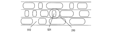
- FIG. 7 is a schematic diagram showing the influence of the degradation region in the information recording layer L2 on the information recording layer L0 and the information recording layer L1. It is considered that the sub area included in the test recording area T2 of the information recording layer L2 is destroyed by the strong irradiation power and the deteriorated areas 130 and 131 are formed.
- the deteriorated area 130 and the deteriorated area 131 have the same size, but the information recording layer L0 is in proportion to the ratio of the deteriorated area 130 in the spot of the laser beam 20 in the information recording layer L2 when the information recording layer L1 is focused.
- the ratio of the deteriorated region 131 to the spot of the laser beam 200 ′ in the information recording layer L2 when focused on is smaller.
- the effect of destroying the sub area included in the test recording area T2 is smaller in the information recording layer L0 than in the information recording layer L1. Therefore, the radial position difference between the test recording area T0 of the information recording layer L0 and the test recording area T2 of the information recording layer L2 can be reduced as in the test recording area arrangement shown in FIG. Thereby, the influence of the test recording areas of other information recording layers can be suppressed, test recording can be performed correctly in each test recording area, and the recording power used in each information recording layer can be determined correctly. Further, the area of the lead-in area can be reduced and a sufficient data area can be secured.
- a pair of test recording regions T2 and T1 formed on a pair of adjacent information recording layers L1 and L2 located on the side closer to the incident surface of the laser beam 200, respectively.
- the distance between the regions T1 and T0 in the radial direction was set larger.
- the distance in the thickness direction between the information recording layer L0 and the information recording layer L1 is shorter than the distance in the thickness direction between the information recording layer L1 and the information recording layer L2, for example, as shown in FIG.
- the thickness of the intermediate layer 111 is smaller than the thickness of the intermediate layer 112, it is considered that the influence between the information recording layer L0 and the information recording layer L1 is larger than that between the information recording layer L1 and the information recording layer L2.
- the radial position difference between the test recording areas T2 and T1 of the adjacent information recording layers L2 and L1 located on the side closer to the incident surface is set to the side far from the incident surface. May be smaller than the radial position difference between the test recording areas T1 and T0 of the adjacent information recording layers L1 and L0.
- the radial position difference (interval) between the test recording areas T2 and T1 of the adjacent information recording layers L2 and L1 located closer to the laser light incident surface is reduced to the limit.
- the radial position difference interval between the test recording regions T1 and T0 of the adjacent information recording layers L1 and L0 located on the far side from the laser light incident surface is defined as the laser light incident surface.
- the optical disc 101 has three information recording layers, but the present invention can also be applied to an optical disc having four or more information recording layers.
- the information recording layer L0, L1, L2 is L0, the information recording layer farthest from the laser light incident surface, and the information recording layer is adjacent to L0.
- L1 and L2 are preferably provided in this order.
- the information recording medium according to the present invention is also a write-once type or a rewritable type.
- the optical disc of the second embodiment is different from the optical disc 101 of the first embodiment in that it further includes an information recording layer L3 and includes four information recording layers.
- an information recording layer L3 is provided between the information recording layer L2 and the cover layer 113, and a new intermediate layer is provided between the information recording layer L3 and the information recording layer L2.
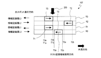
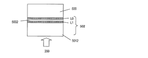
- FIG. 9 is a schematic cross-sectional view of the optical disc 105 of the second embodiment. As in FIG. 2, the intermediate layer is not shown. As shown in FIG. 9, a lead-in area R3 is provided on the inner peripheral side of the information recording layer L3 added to the structure of the optical disc 101, and a test recording area T3 exists in the lead-in area R3.
- test recording areas T0, T1, and T2 are located in the lead-in areas R0, R1, R2, and R3 of the information recording layers L0, L1, L2, and L3, respectively.
- the test recording areas T0, T1, T2, T3 are arranged at different radial positions, and overlap each other when viewed from the stacking direction of the information recording layers L0, L1, L2, L3, that is, the incident direction of the laser beam 200. Absent.
- the test recording of the information recording layer L1 disposed on the inner peripheral side second from the outer peripheral end T3b of the test recording region T3 of the information recording layer L3 disposed on the innermost peripheral side is performed.
- the inner peripheral end T1a of the region T1 is located on the outer peripheral side, and a gap (interval) is provided so that the test recording regions do not overlap.
- This gap has a distance defined by the difference between the radial position of the inner peripheral end T3b and the radial position of the outer peripheral end T1a.
- the end T0a is located on the outer peripheral side, and a gap having a distance defined by the radial position difference between the inner peripheral end T0a and the outer peripheral end T1b is provided.
- the test recording region T2 of the information recording layer L2 that is the third information recording layer is one layer.
- the test recording area T0 of the information recording layer L0 is located on the outer peripheral side of the test recording area T0 of the information recording layer L0, which is the second information recording layer. It is located on the outer peripheral side from T1.
- the test recording area T2 of the information recording layer L2 is located on the outer peripheral side from the test recording area of the information recording layer L1, and the test recording area T1 of the information recording layer L1 is an information recording layer that is the fourth information recording layer. It is located on the outer peripheral side from the test recording area T3 of L3.
- the test recording area T2 of the third information recording layer L2 is located on the outer peripheral side of the test recording area T0 of the information recording layer L0, and the test recording area T0 of the information recording layer L0 is the test recording area of the information recording layer L3. It is located on the outer peripheral side from the region T3.
- the test recording areas T0, T1, T2, T3 have different radial positions, and the test recording areas T0, T1, T2 and T3 do not overlap in the stacking direction of the information recording layer. Therefore, for example, even if the test recording area T1 of the information recording layer L1 is destroyed, the test recording area T0 of the information recording layer L0 is not affected or hardly affected by the destroyed test recording area T1. The laser beam arrives correctly. Therefore, the test recording can be correctly performed using the test recording area T0 of the information recording layer L0, and the recording power of the information recording layer L0 can be correctly determined. Similarly, even if the test recording areas T2 and T3 of the information recording layers L2 and L3 are destroyed, the recording power of the information recording layers L0, L1 and L2 can be correctly determined.
- test recording areas T0, T1, T2, and T3 change, the test recording areas T0, T1, T2, and T3 in the information recording layers L0, L1, L2, and L3.
- the laser beam reaches correctly. Therefore, the test recording can be correctly performed using the test recording areas T0, T1, T2, and T3 of the information recording layers L0, L1, L2, and L3, and the recording power of the information recording layers L0, L1, L2, and L3 is correctly set. Can be determined.
- tracks are configured so that laser light scans the information recording layers L0 and L2 from the inner periphery toward the outer periphery.
- tracks are configured so that the laser beam scans the information recording layers L1 and L3 from the outer periphery toward the inner periphery.
- test recording areas T0, T1, T2, and T3 are preferably used in the direction opposite to the traveling direction of the laser light spot in each information recording layer, as in the first embodiment.
- the use direction of the area is opposite to the light spot traveling direction, it is possible to reach the area where test recording is performed without passing through the destroyed sub-area.
- the influence of other layers can be reduced and the recording power can be determined correctly.
- the optical disk 105 includes four information recording layers, but the present invention can also be suitably used for an optical disk including four or more information recording layers.
- the number of information recording layers is n (n is an integer of 3 or more) and the n information recording layers are counted from the side farthest from the laser light incident surface, the i th (i is 2).
- the laser beam is scanned from the outer peripheral side toward the inner peripheral side, and in the test recording area, the sub area is used from the inner peripheral side toward the outer peripheral side.
- the laser beam is scanned from the inner circumference side to the outer circumference side, and the sub area is used from the outer circumference side to the inner circumference side in the test recording area.
- a test recording area is provided in each information recording layer in an optical disc having three or more information recording layers. Therefore, even if the information recording layer is laminated, even if the irradiation intensity of the laser beam, the thermal environment, etc. are different for each information recording layer, the test recording area of the information recording layer to be recorded is used. Test recording can be performed in the environment of the information recording layer. Therefore, the optimum recording power for each information recording layer can be determined.
- the information recording layers are arranged at different radial positions so as not to overlap each other in the stacking direction. For this reason, it is possible to perform test recording correctly without being influenced by the recording state of the test recording area of other information recording layers, or to suppress the influence, and correctly determine the recording power used in each information recording layer. can do.
- test recording areas T0, T1, T2, and T3 there is a more preferable arrangement in the test recording areas T0, T1, T2, and T3. This arrangement will be described with reference to FIG.
- the laser light When the information recording layer L0 is irradiated with laser light, the laser light needs to pass through the information recording layers L1, L2, and L3.
- the laser light When the information recording layer L2 is irradiated with laser light, the laser light is used for information recording. It is necessary to pass through the layer L3. For this reason, the laser beam transmittance of the information recording layer L3 is the highest, and the transmittance decreases in the order of the information recording layer L2, the information recording layer L1, and the information recording layer L0.
- the existing information recording layer can be used as the information recording layers L0, L1, and L2, and newly It is desirable to develop only the information recording layer L3 having a high transmittance.
- the information recording layer L3 is required to have a high transmittance, the degree of freedom of design is narrowed, and the recording characteristics are changed by a slight change in recording conditions, for example, a change in recording power, compared to the information recording layers L0, L1, and L2. It is easy to get worse.
- the same relationship is established between the information recording layer L2 and the information recording layer L1 and between the information recording layer L1 and the information recording layer L0. That is, in general, the higher the transmittance of the information recording layer, the narrower the design freedom, and the recording characteristics tend to deteriorate due to slight changes in recording conditions, for example, fluctuations in recording power.
- the information recording layer L3 when the information recording layer L3 is irradiated with laser light, a part of the light passes through the information recording layer L3, is reflected by the information recording layer L2, and returns to the information recording layer L2.
- the test recording area T2 of the information recording layer L2 is destroyed or deteriorated, the reflectance of the test recording area T2 changes, and therefore reflected light and stray light returning from the test recording area T2 to the information recording layer L3
- the amount of the laser beam due to changes also.
- the laser light that reflects in the test recording area T2 as a noise component is a fluctuation of the laser light returning from the test recording area T2 to the information recording layer L3. Is superimposed on. As a result, test recording cannot be performed correctly using the test recording area T3, and the recording power of the information recording layer L3 cannot be determined correctly.
- the optical disc 105 of the present embodiment is positioned so that the radial position difference between the test recording regions of adjacent information recording layers located on the side closer to the laser light incident surface is on the side farther from the laser light incident surface. It is preferable to make it larger than the radial position difference between the test recording areas of adjacent information recording layers. That is, a radial interval (T2a) between a pair of test recording areas T2 and T1 formed in a pair of adjacent information recording layers L1 and L2 located on a side relatively close to the incident surface of the laser beam 200, respectively.
- I a radius between a pair of test recording areas T1 and T0 formed in a pair of adjacent information recording layers L0 and L1 located on the side far from the laser light incident surface, respectively. It is preferable to set it larger than the interval in the direction (the interval between T0a and T1b).
- the i-th information recording layer (i is an integer satisfying 2 ⁇ i ⁇ 3).
- the radial position of the outer peripheral end of the test recording area disposed on the inner peripheral side and the inner peripheral end of the test recording area disposed on the outer peripheral side The inner radius of the test recording area of the jth information recording layer and the test recording area of the j + 1th information recording layer whose radius position difference from the radial position is jth (j is an integer satisfying 1 ⁇ j ⁇ i ⁇ 1) This is larger than the radial position difference between the radial position of the outer peripheral end of the test recording area arranged on the side and the radial position of the inner peripheral end of the test recording area arranged on the outer peripheral side.
- the optical disk 105 includes four information recording layers, but the present invention can also be suitably used for an optical disk including four or more information recording layers.
- the above relationship holds for an integer satisfying 2 ⁇ i ⁇ n ⁇ 1, where n is the number of information recording layers included in the optical disc and is an integer of 3 or more.
- the distance between a pair of information recording layers that are more affected by reflection from adjacent information recording layers is widened, and the influence of reflection from adjacent information recording layers is reduced. be able to. Therefore, correct test recording can be performed in the test recording area of each information recording layer, and the recording power used in each information recording layer can be correctly determined. Also, by reducing the distance between a pair of information recording layers that are relatively less affected by reflection from adjacent information recording layers, the distance between the information recording layers is not set larger than necessary, and lead-in is performed. The area of the region can be used effectively. In addition, a sufficient data area can be secured without expanding the lead-in area.
- test recording area T0 in the information recording layer L0 and the test recording area T1 in the information recording layer L1 are defined as two existing information recording layers. It may be made to coincide with the arrangement of the test recording area in the optical disc having In this case, test recording can be performed in the test recording areas T0 and T1 of the optical disc 101 of the present embodiment with only a relatively simple sequence change in the existing optical disc apparatus.
- the four test recording areas T0, T1, T2, and T3 are provided at different radial positions so as not to overlap each other.
- the influence of the reflected light of the information recording layer L2 on the information recording layer L3 on the information recording layer L2, and the information recording on the information recording layer L1 When the influence of the transmitted light of the layer L3 and the influence of the transmitted light of the information recording layer L2 on the information recording layer L0 are small, the test recording area T0 of the information recording layer L0 and the information recording are recorded as in the optical disc 106 shown in FIG.
- the radial position difference of the test record T2 of the layer L2 and the radial position difference of the test recording area T1 of the information recording layer L1 and the test recording area T3 of the information recording layer L3 are compared with the corresponding radial position difference in the arrangement shown in FIG. It may be small.
- FIG. 9 shows a case where the radial position difference between the test recording area T0 and the test recording area T2 and the radial position difference between the recording area T1 and the test recording area T3 are set to zero. Therefore, the inner peripheral end T2a and the outer peripheral end T2b of the test recording area T2 completely coincide with the inner peripheral end T0a and the outer peripheral end T0b of the test recording area T0, and the test recording area T2 and the test recording area T0. Are completely overlapping.
- the inner peripheral end T3a and the outer peripheral end T3b of the test recording area T3 are completely coincident with the inner peripheral end T1a and the outer peripheral end T1b of the test recording area T1, and the test recording area T3 and the test recording area T1 are It is completely overlapping.
- the test recording area T2 may partially overlap the test recording area T0.
- the test recording area T3 may partially overlap with the test recording area T1.
- the test recording area of the information recording layer close to the incident surface side of the laser beam 200 may be arranged close to the information recording layer close to the side far from the incident surface.
- the kth information recording layer (k is an integer satisfying 1 ⁇ k ⁇ 2).
- the radial position of the inner peripheral end of the test recording area arranged on the inner peripheral side and the outer peripheral end of the test recording area arranged on the outer peripheral side is the inner peripheral end of the test recording area arranged on the inner peripheral side. It may be larger than the radial position difference between the radial position and the radial position of the outer peripheral end of the test recording area arranged on the outer peripheral side.
- test recording area T1 of the information recording layer L1 and the test recording area T2 of the information recording layer L2 are arranged on the radial position and the outer peripheral side of the inner peripheral end T1a of the test recording area T1 arranged on the inner peripheral side.
- the test is arranged on the inner circumference side of the test recording area T1 of the information recording layer L1 and the test recording area T3 of the information recording layer L3 so that the radial position difference from the radial position of the outer peripheral end T2b of the test recording area T2 It may be larger than the radial position difference between the radial position of the inner peripheral end T3a of the recording area T3 and the radial position T1b of the outer peripheral end of the test recording area T1 disposed on the outer peripheral side.
- the optical disk 105 includes four information recording layers, but the present invention can also be suitably used for an optical disk including four or more information recording layers.
- the first relationship is established for an integer that satisfies 1 ⁇ k ⁇ n ⁇ 2, where n is the number of information recording layers included in the optical disc and is an integer of 3 or more. .
- the second relationship is that the test recording area of the k′th information recording layer (k ′ is an integer satisfying 1 ⁇ k ′ ⁇ n ⁇ 3) and the test recording area of the k ′ + 1th information recording layer Among these, the radial position difference between the radial position of the inner peripheral end of the test recording area arranged on the inner peripheral side and the radial position of the outer peripheral end of the test recording area arranged on the outer peripheral side is k ′ + 1th.
- the test recording area disposed on the radial position and the outer circumferential side of the inner circumferential end of the test recording area disposed on the inner circumferential side It is defined to be larger than the radial position difference from the radial position of the outer peripheral end of the region.
- the influence of the test recording area of the other information recording layer can be suppressed, the test recording can be performed correctly in each test recording area, and the recording power used in each information recording layer can be determined correctly. Further, the area of the lead-in area can be reduced and a sufficient data area can be secured.
- FIG. 11 shows the case where the radial position difference between the test recording area T1 and the test recording area T3 is zero, but the test recording area T3 is arranged so that the test recording area T3 partially overlaps the test recording area T1. May be. Thereby, the area of the lead-in area can be reduced and a sufficient data area can be secured.
- the optical recording medium 108 shown in FIG. 12 shows the case where the radial position difference between the test recording area T0 and the test recording area T3 is zero, but the test recording area T3 is arranged so that the test recording area T3 partially overlaps the test recording area T0. May be. Thereby, the area of the lead-in area can be reduced and a sufficient data area can be secured.
- the optical disc provided with three and four information recording layers is exemplified, and the optical disc of the present invention has been described.
- the optical disc of the present invention is not limited to the first and second embodiments, and may include five or more information recording layers.
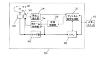
- FIG. 13 is a block diagram of the information recording apparatus 300 of this embodiment.
- the information recording apparatus 300 can record and reproduce data, and includes a spindle motor 302, an optical head 303, a light beam control unit 304, a servo unit 305, a reproduction binarization unit 306, a digital signal processing unit 307, A recording compensation unit 308 and a CPU 309 are provided.
- the optical disc 301 is the optical disc described as the first embodiment or the second embodiment.
- the optical disc 101 of the first embodiment is used as the optical disc 301.
- the spindle motor 302 rotates the optical disc 301 at a predetermined speed, and the optical head 303 irradiates the optical disc 301 with a light beam. Further, the reflected light applied to the optical disc 301 with the light beam is converted into an electrical signal, and a reproduction signal is output.
- the light beam control unit 304 controls the irradiation power of the light beam output from the optical head 303 based on an instruction from the CPU 309.
- the servo unit 305 performs control of the position of the optical head 303 and the light beam emitted from the optical head 303, focus and tracking control of the light beam, and rotation control of the spindle motor 302.
- the reproduction binarization unit 306 amplifies the reproduction signal obtained from the optical head 303 (data information is a sum signal, and information relating to the disk information area and address is a difference signal) and performs binarization processing to obtain a binary signal. Generate a signal. A clock synchronized with the binarized signal is generated by an internal PLL (not shown).
- the digital signal processing unit 307 performs predetermined demodulation processing and error correction processing on the binarized signal. At the time of data recording, processing for adding an error correction code to recording data and predetermined modulation processing are performed to generate modulation data.
- the recording compensation unit 308 converts the modulation data into optical modulation data composed of a pulse train, and further determines the pulse width of the optical modulation data based on a reproduction signal in the disk information area and data stored in the CPU 309 in advance. It is finely adjusted and converted to a recording pulse signal suitable for pit formation.
- the CPU 309 controls the information recording apparatus 300 as a whole.
- the host unit 310 includes, for example, a computer (not shown), an application (not shown), and an operating system (not shown), and requests the optical disc drive 300 to perform recording and reproduction.
- the optical head 303 When the optical disc 301 is loaded in the information recording apparatus 300, the optical head 303 reproduces the control area of the lead-in area R0 of the information recording layer L0 with a predetermined irradiation power by the light beam control unit 304 and the servo unit 305, and the information Recording parameter information such as irradiation power information when recording on the recording layer L0, the information recording layer L1, and the information recording layer L2 is read.
- the optical head 303 When there is a recording request from the host unit 310, the optical head 303 reproduces the test recording area T0 provided in the lead-in area R0 of the information recording layer L0 with a predetermined irradiation power by the light beam control unit 304 and the servo unit 305. To do.
- the CPU 309 sets the irradiation power for performing the test recording in the light beam control unit 304, records test data using a plurality of different irradiation powers by the optical head 303, and reproduces the recorded test data. Based on the error rate and jitter of the obtained reproduction signal, the recording power for recording in the data area D0 of the information recording layer L0 is determined.
- the optical head 303 reproduces the test recording area T1 provided in the lead-in area R1 of the information recording layer L1 with a predetermined irradiation power by the light beam control unit 304 and the servo unit 305.
- the CPU 309 sets the irradiation power for performing the test recording in the light beam control unit 304, records test data using a plurality of different irradiation powers by the optical head 303, and reproduces the recorded test data. Based on the error rate and jitter of the obtained reproduced signal, the recording power for recording in the data area D1 of the information recording layer L1 is determined.
- the optical head 303 reproduces the test recording area T2 provided in the lead-in area R2 of the information recording layer L2 with a predetermined irradiation power by the light beam control unit 304 and the servo unit 305.
- the CPU 309 sets the irradiation power for performing the test recording in the light beam control unit 304, records test data using a plurality of different irradiation powers by the optical head 303, and reproduces the recorded test data. Based on the error rate and jitter of the obtained reproduction signal, the recording power for recording in the data area D2 of the information recording layer L2 is determined. In this way, the recording power for recording information in the data areas D0, D1, and D2 of all the information recording layers L0, L1, and L2 is determined.
- the disk information recorded in the control area is reproduced, and the obtained disk information is used.
- the user data recorded in the data areas D0, D1, and D2 is reproduced.
- test recording areas T0, T1, and T2 are provided only on the inner circumference of the disc, but the test recording areas may also be provided on the outer circumference. Further, when there is a recording request, all recording powers for recording in the data areas D0, D1, D2 of all the information recording layers L0, L1, L2 are determined. However, if the CPU 309 determines that the recording of the requested information is completed by performing recording only on the information recording layer L0, it is only necessary to determine the irradiation power for recording in the data area R0. As a result, it is possible to shorten the time required to start recording user data.
- all recording powers for recording in the data areas of all information recording layers are determined when a recording request is made.
- information to be recorded first is determined by the CPU 309.
- the recording power of the recording layer may be determined, and the recording power of the remaining information recording layers may be determined at another timing. As a result, it is possible to shorten the time required to start recording user data.
- a plurality of patterns of information recording layers or number of layers for test recording are prepared in advance, for example, the CPU 309 predicts whether or not recording of two or more layers is necessary, and recording of two or more layers is unnecessary. For example, by performing only the test recording of the information recording layer L0 and the information recording layer L1, the time until the start of user data recording can be shortened.
- BD Blu-ray disc
- other standard optical discs As an example of a recording medium to which the present invention is applicable, there are a Blu-ray disc (BD) and other standard optical discs.
- BD Blu-ray disc
- this embodiment an example in which the optical discs of the first and second embodiments are applied to a BD will be described. To do.
- BDs such as a BD-ROM that is a read-only type, a BD-R that is a write once / write once type, and a BD-RE that is a rewritable type, depending on the characteristics of the recording film.
- the present invention can be applied to any type of recording medium of ROM (reproduction-only type), R (write-once type / write-once type), and RE (rewritable type) in optical disks of BD and other standards.
- the main optical constants and physical formats of Blu-ray Discs can be found on the white papers posted on the Blu-ray Disc Reader (Ohm Publishing) and the Blu-ray Association website (http://www.blu-raydisc.com/). It is disclosed.
- the laser beam with a wavelength of about 405 nm 400 to 410 nm if the tolerance of the error range is ⁇ 5 nm with respect to the standard value of 405 nm) and the numerical aperture (NA) is about 0.85 (standard value). If the tolerance of the error range is ⁇ 0.01 with respect to 0.85, an objective lens of 0.84 to 0.86) is used.
- the track pitch of the BD is approximately 0.32 ⁇ m (0.310 to 0.330 ⁇ m if the tolerance of the error range is ⁇ 0.010 ⁇ m with respect to the standard value of 0.320 ⁇ m), and one information recording layer or Two layers are provided.
- the recording surface of the information recording layer has a structure of one single layer or two single layers from the laser light incident side, and the distance from the surface of the protective layer of the BD to the recording surface is 75 ⁇ m to 100 ⁇ m.
- the recording signal modulation method uses 17PP modulation, and the mark of the shortest mark to be recorded (2T mark: T is the period of the reference clock (the reference period of modulation in the case of recording a mark by a predetermined modulation rule))
- T is the period of the reference clock (the reference period of modulation in the case of recording a mark by a predetermined modulation rule)
- the length is 0.149 ⁇ m (or 0.138 ⁇ m) (channel bit length: T is 74.50 nm (or 69.00 nm)).
- the recording capacity is single-sided single layer 25 GB (or 27 GB) (more specifically 25.005 GB (or 27.020 GB)), or single-sided double layer 50 GB (or 54 GB) (more specifically 50.050 GB (or 54 .040 GB)).
- the channel clock frequency is 66 MHz (channel bit rate 66.000 Mbit / s) at a transfer rate of standard speed (BD1x), 264 MHz (channel bit rate 264.000 Mbit / s) at a transfer rate of quadruple speed (BD4x), 6
- the transfer rate at double speed (BD6x) is 396 MHz (channel bit rate 396.000 Mbit / s), and the transfer rate at 8 times speed (BD8x) is 528 MHz (channel bit rate 528.000 Mbit / s).
- the standard linear velocity (reference linear velocity, 1x) is 4.917 m / sec (or 4.554 m / sec).
- the linear velocities of 2x (2x), 4x (4x), 6x (6x) and 8x (8x) are 9.834 m / sec, 19.668 m / sec, 29.502 m / sec and 39.50, respectively. 336 m / sec.
- the linear velocity higher than the standard linear velocity is generally a positive integer multiple of the standard linear velocity, but is not limited to an integer and may be a positive real multiple. Also, a linear velocity that is slower than the standard linear velocity, such as 0.5 times (0.5x), may be defined.
- the above-mentioned various conditions mainly relate to one-layer or two-layer BD of about 25 GB (or about 27 GB) per layer that has already been commercialized.
- a high-density BD having a recording capacity per layer of about 32 GB or about 33.4 GB, or a BD having three or four layers has been studied.
- an example in which the present invention is applied to such a BD will be described.
- FIG. 14 A configuration example of such a multilayer disk is shown in FIG. 14 includes (n + 1) information recording layers 502 (n is an integer of 0 or more). Specifically, on the optical disc, a cover layer 501, (n + 1) information recording layers (Ln to L0 layers) 502, and a substrate 500 are laminated in order from the surface on the side where the laser beam 200 is incident.
- an intermediate layer 503 serving as an optical buffer material is inserted between each of the (n + 1) information recording layers 502. That is, information is provided so that the reference layer (L0) is provided at the farthest position (the farthest from the light source) at a predetermined distance from the light incident surface, and the layers are increased from the reference layer (L0) to the light incident surface side. Recording layers are stacked (L1, L2,..., Ln).
- the distance from the light incident surface to the reference layer L0 in the multilayer disc is substantially the same as the distance from the light incident surface to the information recording layer in the single-layer disc (for example, about 0.1 mm). It may be.
- the distance to the innermost layer is made constant (that is, the same distance as in the case of a single layer disc), regardless of whether it is a single layer or multiple layers. Compatibility regarding access to the reference layer can be maintained.
- the traveling direction of the spot (also referred to as a track direction or a spiral direction), it may be a parallel path or an opposite path.
- the traveling direction of the spots is the same in all information recording layers. That is, the traveling direction of the spot proceeds from the inner circumference to the outer circumference in all information recording layers, or from the outer circumference to the inner circumference in all information recording layers.
- the traveling direction of the spot is reversed between an information recording layer and an information recording layer adjacent to the information recording layer. That is, when the traveling direction of the spot in the reference layer (L0) is the direction from the inner periphery to the outer periphery, the traveling direction of the spot in the information recording layer L1 is the direction from the outer periphery to the inner periphery, and in the information recording layer L2, The direction is from the inner periphery to the outer periphery.
- the traveling direction of the spot is the direction from the inner periphery to the outer periphery in the information recording layer Lm (m is 0 and an even number), and the direction from the outer periphery to the inner periphery in the information recording layer Lm + 1.
- the direction is from the outer periphery to the inner periphery
- the information recording layer Lm + 1 the direction is from the inner periphery to the outer periphery.
- the thickness of the protective layer (cover layer) is set to be thinner so that the numerical aperture NA increases, the focal length becomes shorter, and the effect of spot distortion due to tilt can be suppressed.
- the numerical aperture NA is set to 0.45 for CD and 0.65 for DVD, and approximately 0.85 for BD.
- the thickness of the protective layer may be 10 to 200 ⁇ m out of the total thickness of the information recording medium of about 1.2 mm. More specifically, on a substrate of about 1.1 mm, a transparent protective layer of about 0.1 mm for a single-layer disc, and an intermediate layer (SpacerLayer of about 0.025 mm on a protective layer of about 0.075 mm for a dual-layer disc. ) May be provided.
- FIG. 15 shows a configuration example of a single-layer disc
- FIG. 16 shows a configuration example of a two-layer disc
- FIG. 17 shows a configuration example of a three-layer disc
- FIG. 18 shows a configuration example of a four-layer disc.
- the total thickness of the disk is about 1.2 mm in any disk (in the case of including label printing or the like, 1.40 mm or less).
- the thickness of the substrate 500 is approximately 1.1 mm.
- the distance from the light irradiation surface to the reference layer L0 is approximately 0.1 mm.
- the thickness of the cover layer 5011 is approximately 0.1 mm.
- the cover layer 5012 has a thickness of approximately 0.075 mm, and the intermediate layer 5302 has a thickness of approximately 0.025 mm.
- the thickness of the cover layer 5014 and / or The thickness of the intermediate layer 5304 may be further reduced.
- Aberration correction means corrects aberration components such as spherical aberration caused by the thickness from the surface of the protective layer of the optical information recording medium to the information recording layer for recording and reproducing information. Gives an aberration that cancels the component.
- This aberration correction means is originally optically designed so as to reduce the aberration with respect to the information recording layer of the single-layer structure medium, and also takes into account aberrations in recording and reproduction of the information recording medium having a two-layer structure.
- the designed minimum aberration position is set to about 80 ⁇ m to 90 ⁇ m from the surface of the protective layer. For this reason, when the recording / reproducing light is narrowed down to the information recording layer having a thickness different from the minimum aberration position, it is necessary to control the aberration correction unit to set and correct the aberration correction value suitable for each information recording layer.
- FIG. 19 shows a physical configuration of the optical disc 510 according to the present embodiment.
- a large number of tracks 511 are formed concentrically or spirally, and each track 512 has a large number of finely divided sectors.
- data is recorded in each track 512 in units of blocks 513 having a predetermined size.
- the optical disc 510 has a larger recording capacity per information recording layer than a conventional optical disc (for example, a 25 GB BD).
- the expansion of the recording capacity is realized by improving the recording linear density, for example, by reducing the mark length of the recording mark recorded on the optical disc.
- “to improve the recording linear density” means to shorten the channel bit length.
- the channel bit is a length corresponding to the period T of the reference clock (the reference period T of modulation when a mark is recorded by a predetermined modulation rule).
- the optical disk 510 may be multilayered. However, in the following, only one information recording layer is mentioned for convenience of explanation.
- the recording linear density may be different for each layer.
- the track 512 is divided into blocks 513 every 64 kB (kilobytes) of data recording, and block address values are assigned in order.
- Block 513 is divided into sub-blocks of a predetermined length, and one sub-block is composed of three sub-blocks. Subblock numbers 0 to 2 are assigned to the subblocks in order from the front.
- FIG. 20A shows an example of a 25 GB BD.
- the wavelength of the laser beam 200 is 405 nm
- the numerical aperture (NA) of the objective lens 220 is 0.85.
- recorded data is recorded as physical change mark rows 520 and 521 on a track 512 of an optical disc.
- the shortest mark in the mark row is called the “shortest mark”.
- the mark 521 is the shortest mark.
- the physical length of the shortest mark 521 is 0.149 ⁇ m. This is equivalent to approximately 1 / 2.7 of DVD, and even if the wavelength parameter (405 nm) and NA parameter (0.85) of the optical system are changed to increase the resolution of the laser, the light beam identifies the recording mark. We are approaching the limit of optical resolution that is possible.
- FIG. 21 shows a state in which the mark beam recorded on the track 512 is irradiated with a light beam.
- the diameter of the light spot 210 is about 0.39 ⁇ m due to the optical system parameters.
- the recording linear density is improved without changing the structure of the optical system, the recording mark becomes relatively small with respect to the spot diameter of the light spot 210, so that the reproduction resolution is deteriorated.
- FIG. 20B shows an example of an optical disc having a higher recording density than a 25 GB BD.
- the wavelength of the laser 200 is 405 nm
- the numerical aperture (NA) of the objective lens 220 is 0.85.
- the shortest mark 525 has a physical length of 0.1115 ⁇ m.
- the spot diameter is about 0.39 ⁇ m, but the recording mark becomes relatively small and the mark interval becomes narrow, so that the reproduction resolution is deteriorated.
- the amplitude of the reproduction signal when the recording mark is reproduced with the light beam decreases as the recording mark becomes shorter, and becomes zero at the limit of optical resolution.
- the reciprocal of the recording mark period is called a spatial frequency, and the relationship between the spatial frequency and the signal amplitude is called OTF (Optical-Transfer-Function).
- OTF Optical-Transfer-Function
- the signal amplitude decreases almost linearly as the spatial frequency increases.
- the limit frequency of reproduction at which the signal amplitude becomes zero is called OTF cut-off.
- FIG. 22 is a graph showing the relationship between the OTF and the shortest recording mark in a BD having a recording capacity of 25 GB.
- the spatial frequency of the shortest mark of the BD is about 80% with respect to the OTF cutoff, and is close to the OTF cutoff. It can also be seen that the amplitude of the reproduction signal of the shortest mark is very small, about 10% of the maximum detectable amplitude.
- the recording capacity in the BD corresponds to about 31 GB.
- the resolution of the laser may be limited or exceeded, and the reproduction amplitude of the reproduction signal becomes small. This is a region where the S / N ratio deteriorates rapidly.
- the recording linear density of the high recording density optical disk in FIG. 20B is the case where the frequency of the shortest mark of the reproduction signal is near the OTF cutoff frequency (the OTF cutoff frequency or less but not much lower than the OTF cutoff frequency). In this case, it can be assumed that the frequency is higher than the OTF cutoff frequency.
- FIG. 23 is a graph showing an example of the relationship between the signal amplitude and the spatial frequency when the spatial frequency of the shortest mark (2T) is higher than the OTF cutoff frequency and the amplitude of the 2T reproduction signal is 0. It is.
- the 2T spatial frequency of the shortest mark length is 1.12 times the OTF cutoff frequency.
- the SN ratio deterioration due to the multilayer information recording layer may be unacceptable from the viewpoint of the system margin.
- the S / N ratio deterioration becomes remarkable when the frequency of the shortest recording mark exceeds the OTF cutoff frequency.
- the recording linear density has been described above by comparing the frequency of the reproduction signal of the shortest mark with the OTF cutoff frequency.
- the density of the BD is further increased, the above-described relationship between the frequency of the reproduction signal of the next shortest mark (and the next shortest mark (and the recording mark higher than the next shortest mark)) and the OTF cutoff frequency is as described above.
- recording densities recording line density, recording capacity
- ⁇ Recording density and number of layers when the spatial frequency of the shortest mark is in the vicinity of the OTF cutoff frequency, for example, approximately 29 GB ( For example, 29.0 GB ⁇ 0.5 GB, or 29 GB ⁇ 1 GB, or more, or about 30 GB (for example, 30.0 GB ⁇ 0.5 GB, or 30 GB ⁇ 1 GB, etc.) or more, or about 31 GB (for example, 31.0 GB ⁇ 0.5 GB, or 31 GB ⁇ 1 GB) or more, or approximately 32 GB (eg, 32.0 GB ⁇ 0.5 GB, or 32 GB ⁇ 1 GB) or more can be assumed. is there.
- the recording capacity per layer when the spatial frequency of the shortest mark is equal to or higher than the OTF cutoff frequency is, for example, approximately 32 GB (for example, 32.0 GB ⁇ 0.5 GB or 32 GB ⁇ 1 GB) or more, or more Approximately 33 GB (for example, 33.0 GB ⁇ 0.5 GB, or 33 GB ⁇ 1 GB) or more, or approximately 33.3 GB (for example, 33.3 GB ⁇ 0.5 GB, or 33.3 GB ⁇ 1 GB) or more Or approximately 33.4 GB (eg, 33.4 GB ⁇ 0.5 GB, or 33.4 GB ⁇ 1 GB) or more, or approximately 34 GB (eg, 34.0 GB ⁇ 0.5 GB, or 34 GB ⁇ 1 GB, etc.) or More than or about 35 GB (for example, 35.0 GB ⁇ 0.5 GB, or Can be assumed to be 35 GB ⁇ 1 GB or the like.
- 35 GB for example, 35.0 GB
- the recording density is about 33.3 GB
- a recording capacity of about 100 GB (99.9 GB) can be realized with three layers
- a recording capacity of 100 GB or more (100.2 GB) with three layers is achieved. realizable.
- the configuration of the optical disk is a four-layer structure of 25 GB per layer or a three-layer structure of 33 to 34 GB per layer.
- Multi-layering is accompanied by a decrease in reproduction signal amplitude (deterioration of SN ratio) in each information recording layer, influence of multi-layer stray light (signal from an adjacent information recording layer), and the like. Therefore, by using a 33-34 GB three-layer disk instead of a 25 GB four-layer disk, approximately 100 GB can be obtained with a smaller number of layers (three layers instead of four layers) while minimizing the effects of such stray light. It can be realized.
- a disc manufacturer who wants to achieve about 100 GB while avoiding multi-layering as much as possible can select three layers of 33 to 34 GB.
- a disc manufacturer who wants to realize about 100 GB with the conventional format (recording density 25 GB) can select 25 GB of four layers.
- manufacturers having different purposes can achieve the respective purposes with different configurations, and can give a degree of freedom in disc design.
- the recording density per layer is about 30 to 32 GB, a 3-layer disc does not reach 100 GB (about 90 to 96 GB), and a 4-layer disc can achieve 120 GB or more.
- the recording density is about 32 GB, a recording capacity of about 128 GB can be realized with a four-layer disc.
- the number 128 is also a numerical value that matches the power of 2 (2 to the 7th power), which is convenient for processing by a computer.
- the reproduction characteristic for the shortest mark is not stricter.
- a combination of a plurality of types of recording densities and the number of layers can be used for disc manufacturers.
- design freedom For example, a manufacturer who wants to increase the capacity while suppressing the influence of multi-layering has an option of manufacturing about 100 GB of a three-layer disc by three layers of 33 to 34 GB, while suppressing the influence on the reproduction characteristics.
- an option of manufacturing a four-layer disc of about 120 GB or more by forming four layers of 30 to 32 GB can be given.
- the optimum recording power for each information recording layer can be determined by adopting the structure of the optical disc of the first embodiment or the second embodiment. Therefore, particularly when the linear recording density is increased, even when it is required to form the recording mark more accurately, appropriate recording can be performed using the optimum recording power.
- the present invention is suitably used for various information recording media and information recording devices, and particularly suitably used for a write once or rewritable information recording medium having three or more information recording layers and an information recording device corresponding thereto. It is done.
Landscapes
- Physics & Mathematics (AREA)
- Optics & Photonics (AREA)
- Optical Recording Or Reproduction (AREA)
- Optical Head (AREA)
- Optical Record Carriers And Manufacture Thereof (AREA)
Priority Applications (10)
| Application Number | Priority Date | Filing Date | Title |
|---|---|---|---|
| RU2010136726/28A RU2498424C2 (ru) | 2008-08-07 | 2009-08-06 | Носитель для записи информации и устройство записи информации |
| BRPI0907851-7A BRPI0907851B1 (pt) | 2008-08-07 | 2009-08-06 | meio de gravação de informação e dispositivo de gravação de informação |
| CN2009801072926A CN101960520A (zh) | 2008-08-07 | 2009-08-06 | 信息记录介质和信息记录装置 |
| KR1020107024646A KR101029388B1 (ko) | 2008-08-07 | 2009-08-06 | 정보 기록 매체 및 정보 기록 장치 |
| EP09804751A EP2264702B1 (en) | 2008-08-07 | 2009-08-06 | Information recording medium, reading method and systems for reading and writing the medium |
| JP2010523767A JP4616422B2 (ja) | 2008-08-07 | 2009-08-06 | 情報記録媒体および再生方法 |
| ES09804751T ES2399804T3 (es) | 2008-08-07 | 2009-08-06 | Medio de grabación de información, método de lectura y sistemas para leer y escribir el medio |
| MX2010009489A MX2010009489A (es) | 2008-08-07 | 2009-08-06 | Medio de grabacion de informacion y dispositivo de grabacion de informacion. |
| US12/918,107 US20100329100A1 (en) | 2008-08-07 | 2009-08-06 | Information recording medium and information recording device |
| ZA2011/01375A ZA201101375B (en) | 2008-08-07 | 2011-02-21 | Information recording medium and information recording device |
Applications Claiming Priority (2)
| Application Number | Priority Date | Filing Date | Title |
|---|---|---|---|
| US8684408P | 2008-08-07 | 2008-08-07 | |
| US61/086,844 | 2008-08-07 |
Publications (1)
| Publication Number | Publication Date |
|---|---|
| WO2010016264A1 true WO2010016264A1 (ja) | 2010-02-11 |
Family
ID=41663491
Family Applications (1)
| Application Number | Title | Priority Date | Filing Date |
|---|---|---|---|
| PCT/JP2009/003782 WO2010016264A1 (ja) | 2008-08-07 | 2009-08-06 | 情報記録媒体および情報記録装置 |
Country Status (13)
| Country | Link |
|---|---|
| US (3) | US20100329100A1 (ko) |
| EP (1) | EP2264702B1 (ko) |
| JP (5) | JP4616422B2 (ko) |
| KR (3) | KR20110027788A (ko) |
| CN (1) | CN101960520A (ko) |
| BR (1) | BRPI0907851B1 (ko) |
| ES (1) | ES2399804T3 (ko) |
| MX (1) | MX2010009489A (ko) |
| MY (1) | MY151266A (ko) |
| RU (1) | RU2498424C2 (ko) |
| TW (1) | TW201011743A (ko) |
| WO (1) | WO2010016264A1 (ko) |
| ZA (1) | ZA201101375B (ko) |
Cited By (3)
| Publication number | Priority date | Publication date | Assignee | Title |
|---|---|---|---|---|
| WO2011002104A1 (ja) * | 2009-07-03 | 2011-01-06 | ソニー株式会社 | 記録可能型光ディスク、記録装置、記録方法、再生装置 |
| WO2011002106A1 (ja) * | 2009-07-03 | 2011-01-06 | ソニー株式会社 | 記録可能型光ディスク、記録装置、記録方法 |
| US10954330B2 (en) | 2017-07-27 | 2021-03-23 | Trinseo Europe Gmbh | Use of specific aminosilyl monomers in the manufacture of rubber |
Families Citing this family (9)
| Publication number | Priority date | Publication date | Assignee | Title |
|---|---|---|---|---|
| JP2008310922A (ja) | 2007-06-18 | 2008-12-25 | Toshiba Corp | 情報記録媒体及びこの媒体を用いたディスク装置 |
| JP2010009685A (ja) * | 2008-06-27 | 2010-01-14 | Sony Corp | 多層光記録媒体、記録装置、記録レーザパワー調整方法 |
| KR20110027788A (ko) * | 2008-08-07 | 2011-03-16 | 파나소닉 주식회사 | 정보 기록 매체 및 정보 기록 장치 |
| JP5380331B2 (ja) * | 2010-03-01 | 2014-01-08 | 株式会社日立エルジーデータストレージ | 光ディスク、光ディスク装置および再生方法 |
| CN103354938B (zh) * | 2011-02-23 | 2016-07-06 | 松下知识产权经营株式会社 | 光学信息记录介质及光学信息记录装置 |
| JP5273221B2 (ja) * | 2011-07-20 | 2013-08-28 | 船井電機株式会社 | 光ディスク記録装置 |
| JP6035840B2 (ja) * | 2012-04-23 | 2016-11-30 | ソニー株式会社 | 記録装置、記録方法、記録媒体 |
| US10591383B2 (en) * | 2016-08-26 | 2020-03-17 | Oracle International Corporation | Characterizing the I/O-performance-per-watt of a computing device across a range of vibrational operating environments |
| KR102445675B1 (ko) * | 2020-12-07 | 2022-09-22 | 대한민국 | 신규한 바실러스 서브틸리스 균주 및 이를 이용하여 발효한 생강의 기능성 |
Citations (5)
| Publication number | Priority date | Publication date | Assignee | Title |
|---|---|---|---|---|
| JP2002358648A (ja) | 2001-03-28 | 2002-12-13 | Matsushita Electric Ind Co Ltd | 光ディスク装置および記録パワー決定方法 |
| JP2005063628A (ja) * | 2002-12-20 | 2005-03-10 | Mitsubishi Chemicals Corp | 光記録媒体,光記録媒体の記録方法及び記録装置 |
| JP2005529442A (ja) * | 2002-06-07 | 2005-09-29 | エルジー エレクトロニクス インコーポレーテッド | 高密度マルチレイヤ光ディスクと、それに対する光パワー調節方法 |
| JP2006252762A (ja) * | 2006-04-24 | 2006-09-21 | Mitsubishi Electric Corp | 光ディスクの記録方法及び光ディスク |
| JP2007164954A (ja) * | 2005-01-12 | 2007-06-28 | Victor Co Of Japan Ltd | 光ディスク装置及び光ディスクの最適記録パワー値決定方法 |
Family Cites Families (14)
| Publication number | Priority date | Publication date | Assignee | Title |
|---|---|---|---|---|
| US6845071B2 (en) * | 2001-03-28 | 2005-01-18 | Matsushita Electric Industrial Co., Ltd. | Optical disc apparatus and recording power determining method thereof |
| WO2004057585A1 (ja) * | 2002-12-20 | 2004-07-08 | Mitsubishi Chemical Corporation | 光記録媒体,光記録媒体の記録方法及び記録装置 |
| KR100677108B1 (ko) * | 2003-06-12 | 2007-02-01 | 삼성전자주식회사 | 정보 저장매체 |
| JP2005038584A (ja) * | 2003-06-25 | 2005-02-10 | Matsushita Electric Ind Co Ltd | 光ディスクとその製造方法、並びに、この光ディスクを用いたデータの記録方法及び再生方法 |
| US7345973B2 (en) * | 2003-06-26 | 2008-03-18 | Koninklijke Philips Electronics N.V. | Multi-layer writable optical record carrier with an optimum power calibration area, and method and apparatus for forming optimum power calibration areas on such a record carrier |
| JP2005285254A (ja) * | 2004-03-30 | 2005-10-13 | Mitsubishi Electric Corp | 光ディスクの記録方法及び光ディスク |
| KR100677114B1 (ko) * | 2004-04-27 | 2007-02-02 | 삼성전자주식회사 | 정보 저장 매체, 이 정보 저장 매체의 데이터 기록/재생방법 및 장치 |
| JP4249663B2 (ja) * | 2004-06-10 | 2009-04-02 | パイオニア株式会社 | 情報記録媒体、並びに情報記録装置及び方法 |
| TW200627397A (en) * | 2005-01-12 | 2006-08-01 | Victor Company Of Japan | Optical-disc drive apparatus and method of deciding optimum recording powers of laser beam |
| KR20060082513A (ko) * | 2005-01-12 | 2006-07-19 | 엘지전자 주식회사 | 기록매체 및 기록매체의 기록방법과 기록장치 |
| US7357511B2 (en) | 2005-03-23 | 2008-04-15 | 3M Innovative Properties Company | Stress birefringence compensation in polarizing beamsplitters and systems using same |
| WO2008007898A1 (en) | 2006-07-11 | 2008-01-17 | Lg Electronics Inc. | Recording medium, apparatus for recording/reproducing data on/from the same and method thereof |
| US20090154315A1 (en) * | 2007-12-04 | 2009-06-18 | Panasonic Corporation | Information recording medium, recording method, recording apparatus and integrated circuit |
| KR20110027788A (ko) * | 2008-08-07 | 2011-03-16 | 파나소닉 주식회사 | 정보 기록 매체 및 정보 기록 장치 |
-
2009
- 2009-08-06 KR KR1020117001279A patent/KR20110027788A/ko not_active Application Discontinuation
- 2009-08-06 KR KR1020107024646A patent/KR101029388B1/ko active IP Right Grant
- 2009-08-06 MX MX2010009489A patent/MX2010009489A/es active IP Right Grant
- 2009-08-06 CN CN2009801072926A patent/CN101960520A/zh active Pending
- 2009-08-06 RU RU2010136726/28A patent/RU2498424C2/ru active
- 2009-08-06 ES ES09804751T patent/ES2399804T3/es active Active
- 2009-08-06 EP EP09804751A patent/EP2264702B1/en active Active
- 2009-08-06 BR BRPI0907851-7A patent/BRPI0907851B1/pt active IP Right Grant
- 2009-08-06 TW TW098126545A patent/TW201011743A/zh unknown
- 2009-08-06 KR KR1020107019484A patent/KR101016122B1/ko active IP Right Grant
- 2009-08-06 JP JP2010523767A patent/JP4616422B2/ja active Active
- 2009-08-06 MY MYPI20103875 patent/MY151266A/en unknown
- 2009-08-06 US US12/918,107 patent/US20100329100A1/en not_active Abandoned
- 2009-08-06 WO PCT/JP2009/003782 patent/WO2010016264A1/ja active Application Filing
- 2009-08-06 US US12/536,627 patent/US7885171B2/en active Active
-
2010
- 2010-08-06 JP JP2010177304A patent/JP4652482B2/ja active Active
- 2010-10-26 JP JP2010239683A patent/JP4676574B2/ja active Active
- 2010-12-09 JP JP2010274590A patent/JP4714303B2/ja active Active
- 2010-12-20 US US12/972,810 patent/US8144566B2/en active Active
-
2011
- 2011-01-28 JP JP2011017054A patent/JP2011123992A/ja active Pending
- 2011-02-21 ZA ZA2011/01375A patent/ZA201101375B/en unknown
Patent Citations (5)
| Publication number | Priority date | Publication date | Assignee | Title |
|---|---|---|---|---|
| JP2002358648A (ja) | 2001-03-28 | 2002-12-13 | Matsushita Electric Ind Co Ltd | 光ディスク装置および記録パワー決定方法 |
| JP2005529442A (ja) * | 2002-06-07 | 2005-09-29 | エルジー エレクトロニクス インコーポレーテッド | 高密度マルチレイヤ光ディスクと、それに対する光パワー調節方法 |
| JP2005063628A (ja) * | 2002-12-20 | 2005-03-10 | Mitsubishi Chemicals Corp | 光記録媒体,光記録媒体の記録方法及び記録装置 |
| JP2007164954A (ja) * | 2005-01-12 | 2007-06-28 | Victor Co Of Japan Ltd | 光ディスク装置及び光ディスクの最適記録パワー値決定方法 |
| JP2006252762A (ja) * | 2006-04-24 | 2006-09-21 | Mitsubishi Electric Corp | 光ディスクの記録方法及び光ディスク |
Non-Patent Citations (1)
| Title |
|---|
| See also references of EP2264702A4 |
Cited By (6)
| Publication number | Priority date | Publication date | Assignee | Title |
|---|---|---|---|---|
| WO2011002104A1 (ja) * | 2009-07-03 | 2011-01-06 | ソニー株式会社 | 記録可能型光ディスク、記録装置、記録方法、再生装置 |
| WO2011002106A1 (ja) * | 2009-07-03 | 2011-01-06 | ソニー株式会社 | 記録可能型光ディスク、記録装置、記録方法 |
| JP2011014202A (ja) * | 2009-07-03 | 2011-01-20 | Sony Corp | 記録可能型光ディスク、記録装置、記録方法 |
| US8363531B2 (en) | 2009-07-03 | 2013-01-29 | Sony Corporation | Recordable optical disk, recording device, recording method, and reproduction device |
| US8811140B2 (en) | 2009-07-03 | 2014-08-19 | Sony Corporation | Recordable optical disc, recording device, and recording method |
| US10954330B2 (en) | 2017-07-27 | 2021-03-23 | Trinseo Europe Gmbh | Use of specific aminosilyl monomers in the manufacture of rubber |
Also Published As
| Publication number | Publication date |
|---|---|
| BRPI0907851B1 (pt) | 2020-10-13 |
| JP2011014232A (ja) | 2011-01-20 |
| KR20110010710A (ko) | 2011-02-07 |
| TW201011743A (en) | 2010-03-16 |
| JP2011090777A (ja) | 2011-05-06 |
| JPWO2010016264A1 (ja) | 2012-01-19 |
| US20100039921A1 (en) | 2010-02-18 |
| KR101016122B1 (ko) | 2011-02-17 |
| RU2010136726A (ru) | 2012-03-10 |
| US20100329100A1 (en) | 2010-12-30 |
| ZA201101375B (en) | 2011-10-26 |
| EP2264702B1 (en) | 2013-01-23 |
| US8144566B2 (en) | 2012-03-27 |
| KR101029388B1 (ko) | 2011-04-14 |
| JP2011123992A (ja) | 2011-06-23 |
| KR20110027788A (ko) | 2011-03-16 |
| EP2264702A1 (en) | 2010-12-22 |
| JP4652482B2 (ja) | 2011-03-16 |
| MX2010009489A (es) | 2010-09-24 |
| JP4616422B2 (ja) | 2011-01-19 |
| MY151266A (en) | 2014-04-30 |
| JP2011044229A (ja) | 2011-03-03 |
| KR20100125277A (ko) | 2010-11-30 |
| JP4714303B2 (ja) | 2011-06-29 |
| US20110085428A1 (en) | 2011-04-14 |
| RU2498424C2 (ru) | 2013-11-10 |
| CN101960520A (zh) | 2011-01-26 |
| JP4676574B2 (ja) | 2011-04-27 |
| BRPI0907851A2 (pt) | 2019-11-12 |
| EP2264702A4 (en) | 2011-05-18 |
| US7885171B2 (en) | 2011-02-08 |
| ES2399804T3 (es) | 2013-04-03 |
Similar Documents
| Publication | Publication Date | Title |
|---|---|---|
| JP4652482B2 (ja) | 情報記録媒体および再生方法 | |
| RU2511708C2 (ru) | Регистрирующий носитель информации, регистрирующее устройство и воспроизводящее устройство | |
| JP4462182B2 (ja) | 光ディスク装置及び光ディスクの最適記録パワー値決定方法 | |
| US8094543B2 (en) | Information recording medium, reproducing apparatus and reproducing method | |
| JP2005011404A (ja) | 光記録媒体、記録装置及び記録方法 | |
| JP2002329330A (ja) | 情報記録媒体、情報再生装置、情報再生方法 | |
| JP4586096B2 (ja) | 多層光ディスクおよびその記録方法 | |
| JP5563480B2 (ja) | 情報記録媒体、再生装置および再生方法 | |
| JP4315253B2 (ja) | 情報記録媒体 | |
| WO2019111437A1 (ja) | 光ディスク、光ディスクの製造装置、及び光ディスクの製造方法 | |
| JP5727021B2 (ja) | 情報記録媒体、情報再生装置及び管理情報再生方法、情報記録再生装置及び識別情報再生記録方法 | |
| JP5433661B2 (ja) | 光ディスク装置、情報記録方法 | |
| JP4699142B2 (ja) | 検査用光ディスク、および、光ディスクドライブまたは光ピックアップの検査方法 | |
| WO2010050144A1 (ja) | 情報記録媒体、記録装置および再生装置 | |
| JP2006031862A (ja) | 光ディスクおよび光ディスク記録装置 |
Legal Events
| Date | Code | Title | Description |
|---|---|---|---|
| WWE | Wipo information: entry into national phase |
Ref document number: 200980107292.6 Country of ref document: CN |
|
| 121 | Ep: the epo has been informed by wipo that ep was designated in this application |
Ref document number: 09804751 Country of ref document: EP Kind code of ref document: A1 |
|
| ENP | Entry into the national phase |
Ref document number: 2010523767 Country of ref document: JP Kind code of ref document: A |
|
| WWE | Wipo information: entry into national phase |
Ref document number: 12010501869 Country of ref document: PH |
|
| WWE | Wipo information: entry into national phase |
Ref document number: 12918107 Country of ref document: US |
|
| WWE | Wipo information: entry into national phase |
Ref document number: MX/A/2010/009489 Country of ref document: MX |
|
| WWE | Wipo information: entry into national phase |
Ref document number: 5398/CHENP/2010 Country of ref document: IN |
|
| WWE | Wipo information: entry into national phase |
Ref document number: 2010136726 Country of ref document: RU Ref document number: 2009804751 Country of ref document: EP |
|
| ENP | Entry into the national phase |
Ref document number: 20107019484 Country of ref document: KR Kind code of ref document: A |
|
| WWE | Wipo information: entry into national phase |
Ref document number: PI 2010003875 Country of ref document: MY |
|
| NENP | Non-entry into the national phase |
Ref country code: DE |
|
| REG | Reference to national code |
Ref country code: BR Ref legal event code: B01E Ref document number: PI0907851 Country of ref document: BR Free format text: NA PETICAO INICIAL, FALTA NUMERAR AS PRIMEIRAS FOLHAS DO RELATORIO DESCRITIVO, DAS REIVINDICACOES E DO RESUMO. |
|
| REG | Reference to national code |
Ref country code: BR Ref legal event code: B01Y Ref document number: PI0907851 Country of ref document: BR Free format text: ANULADA A PUBLICACAO CODIGO 1.5 NA RPI NO 2540 DE 10/09/2019 POR TER SIDO INDEVIDA. |
|
| ENP | Entry into the national phase |
Ref document number: PI0907851 Country of ref document: BR Kind code of ref document: A2 Effective date: 20100831 |