WO2010050144A1 - 情報記録媒体、記録装置および再生装置 - Google Patents
情報記録媒体、記録装置および再生装置 Download PDFInfo
- Publication number
- WO2010050144A1 WO2010050144A1 PCT/JP2009/005462 JP2009005462W WO2010050144A1 WO 2010050144 A1 WO2010050144 A1 WO 2010050144A1 JP 2009005462 W JP2009005462 W JP 2009005462W WO 2010050144 A1 WO2010050144 A1 WO 2010050144A1
- Authority
- WO
- WIPO (PCT)
- Prior art keywords
- recording
- information recording
- area
- information
- layers
- Prior art date
Links
Images


Classifications
-
- G—PHYSICS
- G11—INFORMATION STORAGE
- G11B—INFORMATION STORAGE BASED ON RELATIVE MOVEMENT BETWEEN RECORD CARRIER AND TRANSDUCER
- G11B7/00—Recording or reproducing by optical means, e.g. recording using a thermal beam of optical radiation by modifying optical properties or the physical structure, reproducing using an optical beam at lower power by sensing optical properties; Record carriers therefor
- G11B7/24—Record carriers characterised by shape, structure or physical properties, or by the selection of the material
- G11B7/2403—Layers; Shape, structure or physical properties thereof
- G11B7/24035—Recording layers
- G11B7/24038—Multiple laminated recording layers
-
- G—PHYSICS
- G11—INFORMATION STORAGE
- G11B—INFORMATION STORAGE BASED ON RELATIVE MOVEMENT BETWEEN RECORD CARRIER AND TRANSDUCER
- G11B7/00—Recording or reproducing by optical means, e.g. recording using a thermal beam of optical radiation by modifying optical properties or the physical structure, reproducing using an optical beam at lower power by sensing optical properties; Record carriers therefor
- G11B7/007—Arrangement of the information on the record carrier, e.g. form of tracks, actual track shape, e.g. wobbled, or cross-section, e.g. v-shaped; Sequential information structures, e.g. sectoring or header formats within a track
- G11B7/00736—Auxiliary data, e.g. lead-in, lead-out, Power Calibration Area [PCA], Burst Cutting Area [BCA], control information
-
- G—PHYSICS
- G11—INFORMATION STORAGE
- G11B—INFORMATION STORAGE BASED ON RELATIVE MOVEMENT BETWEEN RECORD CARRIER AND TRANSDUCER
- G11B7/00—Recording or reproducing by optical means, e.g. recording using a thermal beam of optical radiation by modifying optical properties or the physical structure, reproducing using an optical beam at lower power by sensing optical properties; Record carriers therefor
- G11B7/24—Record carriers characterised by shape, structure or physical properties, or by the selection of the material
- G11B7/2407—Tracks or pits; Shape, structure or physical properties thereof
- G11B7/24073—Tracks
- G11B7/24082—Meandering
Definitions
- the present invention relates to a multilayer optical information recording medium provided with a test recording area (OPC area) for obtaining optimum recording conditions (recording power and / or write strategy) for a plurality of information recording layers, and multilayer optical information
- OPC area test recording area
- the present invention relates to a recording apparatus and a reproducing apparatus that perform recording and / or reproduction on a recording medium.
- optical recording media include BD-R, BD-RE, DVD-RAM, DVD-R, DVD-RW, and CD-RW standards, and data is obtained by irradiating an optical disk conforming to these standards with laser light.
- optical disks are an optical disk using a phase change type recording material as a recording layer.
- a phase change optical disk records information by irradiating an optical disk with a laser beam and locally changing the atomic bonding state of a thin film material formed on the surface of the recording film by the injection energy.
- the reflectance changes due to the difference in the physical state described above.
- Information can be read by detecting the amount of change in reflectance.
- the phase change type optical disc includes a rewritable optical disc using GeSbTe as the recording material of the recording layer and a write-once optical disc using another recording material.
- a recording material for a write-once optical disk Patent Document 1 contains Te—OM (where M is at least one element selected from a metal element, a metalloid element, and a semiconductor element).
- Te-OM is a material containing Te, O and M, and Te, Te-M and M fine particles are uniformly and randomly dispersed in the TeO2 matrix immediately after film formation. It is a composite material.
- a recording mark is formed by irradiating a laser beam modulated in a multi-pulse form to cause a change in the physical state of the recording material.
- Information is read by detecting a change in reflectance.
- the capacity of optical discs has been increasing.
- the recording mark, space length and track pitch are shortened to increase the recording density per surface, and the information recording layer that can be written to or read from the laser light incident surface is multilayered. There is a way to increase the recording capacity.
- an information recording layer that is translucent to the laser beam is disposed on the information recording layer on the laser beam incident side (front side), and an information recording layer is disposed on the far side.
- An optical disc having a plurality of information recording layers needs to be recorded or reproduced in an appropriate state regardless of the recording state of the transmitted information recording layer in all laminated information recording layers. Ensuring is becoming increasingly important.
- test recording area an area for calibrating recording power
- OPC Optimum Power Control
- OPC Optimum Power Control
- JP 2004-362748 A JP 2005-38584 A International Publication No. 2002/023542 Pamphlet Special table 2007-521606 Special table 2007-526595 Special table 2007-521589 gazette Special table 2008-527602
- Patent Documents 2 to 7 are provided with at least two information recording layers for the purpose of preventing adverse effects on the recording medium, and each information recording layer includes an inner area, a data area, and an outer area.
- each OPC area is provided in at least one of the inner area and the outer area, and each of the plurality of information recording layers or each OPC area provided in the adjacent information recording layer has a light beam.
- the transmitted light is affected by the recording state of the previous information recording layer, and adversely affects the recording / reproduction signal quality of the information recording layer on the back side. End up. Even if an optical disc in which the presence or absence of recording in the front information layer does not affect the recording quality in the back information recording layer, if test recording is performed with excessive power in the OPC area of the front information recording layer, It is conceivable that when the laser beam passes through this information recording layer, it is affected by a change in intensity and the like, and in the back information recording layer, the optimum recording power cannot be derived by OPC.
- the information recording layer is laminated in order to eliminate the overlap of the OPC areas at the same physical position with reference to the traveling direction of the light beam.
- the number increases, it is necessary to reduce the physical size occupied by the OPC area per layer or increase the inner area or the outer area. In any of the methods, the number of OPCs has to be reduced, and the user data area for the user to record on the optical disk is reduced.
- the physical area occupied by the OPC area as the number of information recording layers increases.
- the size (number of clusters) must be reduced.
- the number of times of learning the recording power and recording pulse conditions decreases due to the decrease in the physical size of the OPC area.
- the size of the recording mark or space is sufficiently smaller than the spot size of the light spot, the intersymbol interference of the reproduction signal and the thermal interference between the recording marks increase, and the edge shift between the recording mark and the space is noticeably generated To do.
- the number of test recordings must be increased more than before, and write strategy adjustment must be performed more accurately to improve recording signal quality.
- test recording area in the inner area or the outer area is arranged so as not to overlap between the information recording layers as described above, the physical size of the test area of the information recording layer must be reduced, There is a problem that many test recording areas cannot be secured.
- test recording area is required to have random accessibility so that the information recording layers can be used freely rather than sequentially.
- the recording order of recording on each information recording layer is not necessarily completely sequential from the back information recording layer to the front information recording layer as L0 ⁇ L1 ⁇ L2 ⁇ L3. Instead of recording, it is necessary to record continuously in a united section of each information recording layer and freely record between information recording layers. Defect management and file system management will be described as an example where it is necessary to record freely between information recording layers.
- areas called data spare areas (alternate areas) for saving data are defined on the inner and outer circumferences of areas where user data is recorded. They are called ISA (Inner Spare Area) and OSA (Outer Spare Area), respectively.
- ISA Inner Spare Area
- OSA Outer Spare Area
- the optical disk apparatus records data that is scheduled to be recorded in a block that cannot be recorded in an unused area in the replacement area.
- pairs of addresses of replacement sources (defective blocks) and replacement destinations (replacement areas) are registered in a list that manages replacement information called defect lists as replacement information.
- the defect list is secured in the DMA in the inner zone or the outer zone.
- the optical disk device reads the information registered in the defect list. If it is not registered, it reads the data from the specified location, and if it is registered, it actually reads the information based on the replacement information. Read data from where it is written.
- the start side of the logical address In the case of a file system in which information is recorded in order and management information is recorded from the end side of the logical address, it is assumed that an instruction is issued from the host to record data on the end address side.
- the end address of the logical address is the L3 information recording layer in which the physical end address of the optical disk is arranged. Therefore, the recording order between the information recording layers is physically recorded across the information recording layers.
- the optimization of the recording power in the OPC area not only sequentially performs the OPC of the information recording layer on the front side in order from the back layer, but also the optimum recording power, recording pulse condition and servo for all the information recording layers. It is necessary to optimize the conditions in advance.
- An object of the present invention is to provide an information recording medium in which an OPC area is efficiently arranged in an inner area and / or an outer area, and a recording apparatus and a reproducing apparatus corresponding to the information recording medium.
- the information recording medium of the present invention is an information recording medium comprising a plurality of information recording layers of three or more layers, and each of the plurality of information recording layers has a test recording area used for adjusting recording conditions.
- One information recording layer of the plurality of information recording layers includes a read-only management data area in which management data for managing the information recording medium is recorded in advance.
- Each of the other two or more information recording layers includes the test recording area where a radial position overlaps a part of the management data area.
- the reproducing apparatus is a reproducing apparatus for reproducing information recorded on the information recording medium, the irradiation unit irradiating the plurality of information recording layers with laser light, and the irradiation of the irradiated laser light.
- a light receiving unit that receives reflected light and a reproduction unit that reproduces information based on a signal obtained by the light reception.
- the recording apparatus of the present invention is a recording apparatus for recording information on the information recording medium, wherein the recording condition is set using an irradiation unit for irradiating the plurality of information recording layers with laser light and the test recording area. And a recording unit for recording information on the information recording medium under the adjusted recording condition.
- the information recording medium of the present invention is an information recording medium including a plurality of information recording layers of three or more layers, and one information recording layer of the plurality of information recording layers manages the information recording medium.
- the reproducing apparatus is a reproducing apparatus for reproducing information recorded on the information recording medium, the irradiation unit irradiating the plurality of information recording layers with laser light, and the irradiation of the irradiated laser light.
- a light receiving unit that receives reflected light and a reproduction unit that reproduces information based on a signal obtained by the light reception.
- the recording apparatus of the present invention is a recording apparatus for recording information on the information recording medium, wherein the plurality of information recording layers are pre-recorded in an irradiation unit for irradiating the plurality of information recording layers and the reproduction-only management data area.
- the information recording medium of the present invention is an information recording medium comprising a plurality of information recording layers of three or more layers, and each of the plurality of information recording layers has a test recording area used for adjusting recording conditions.
- One information recording layer of the plurality of information recording layers includes a recordable management data area in which management data for managing the information recording medium can be newly written, and a test recording area
- the recordable management data area is arranged on the inner and outer peripheral sides of the test recording area.
- the reproducing apparatus is a reproducing apparatus for reproducing information recorded on the information recording medium, the irradiation unit irradiating the plurality of information recording layers with laser light, and the irradiation of the irradiated laser light.
- a light receiving unit that receives reflected light and a reproduction unit that reproduces information based on a signal obtained by the light reception.
- the recording apparatus of the present invention is a recording apparatus for recording information on the information recording medium, wherein the recording condition is set using an irradiation unit for irradiating the plurality of information recording layers with laser light and the test recording area. And a recording unit for recording information on the information recording medium under the adjusted recording condition.
- the information recording medium of the present invention is an information recording medium comprising a plurality of information recording layers of three or more layers, and at least two of the plurality of information recording layers manage the information recording medium A recordable management data area in which management data for writing can be newly written, and the recordable management data area of one information recording layer of the plurality of information recording layers, and at least one other At least some of the radial positions overlap each other with the recordable management data area of one information recording layer.
- the reproducing apparatus is a reproducing apparatus for reproducing information recorded on the information recording medium, the irradiation unit irradiating the plurality of information recording layers with laser light, and the irradiation of the irradiated laser light.
- a light receiving unit that receives reflected light and a reproduction unit that reproduces information based on a signal obtained by the light reception.
- the recording apparatus of the present invention is a recording apparatus for recording information on the information recording medium, and is recorded in an irradiation unit for irradiating the plurality of information recording layers with laser light and the recordable management data area. And a recording unit that reproduces the management data and records information on the information recording medium based on the management data.
- the information recording medium of the present invention is an information recording medium including a plurality of information recording layers of three or more layers, and one information recording layer of the plurality of information recording layers manages the information recording medium. A plurality of recordable management data areas into which management data for writing can be newly written.
- the reproducing apparatus is a reproducing apparatus for reproducing information recorded on the information recording medium, the irradiation unit irradiating the plurality of information recording layers with laser light, and the irradiation of the irradiated laser light.
- a light receiving unit that receives reflected light and a reproduction unit that reproduces information based on a signal obtained by the light reception.
- the recording apparatus of the present invention is a recording apparatus for recording information on the information recording medium, and is recorded in an irradiation unit for irradiating the plurality of information recording layers with laser light and the recordable management data area. And a recording unit that reproduces the management data and records information on the information recording medium based on the management data.
- the information recording medium of the present invention is an information recording medium including a plurality of information recording layers of three or more layers, and one information recording layer of the plurality of information recording layers manages the information recording medium.
- a plurality of recordable management data areas in which management data can be newly written, and a test recording area used for adjusting a recording condition is provided between the two recordable management data areas. Has been placed.
- the reproducing apparatus is a reproducing apparatus for reproducing information recorded on the information recording medium, the irradiation unit irradiating the plurality of information recording layers with laser light, and the irradiation of the irradiated laser light.
- a light receiving unit that receives reflected light and a reproduction unit that reproduces information based on a signal obtained by the light reception.
- the recording apparatus of the present invention is a recording apparatus for recording information on the information recording medium, wherein the recording condition is set using an irradiation unit for irradiating the plurality of information recording layers with laser light and the test recording area. And a recording unit for recording information on the information recording medium under the adjusted recording condition.
- the information recording medium of the present invention is an information recording medium comprising a plurality of information recording layers of three or more layers, and one information recording layer of the plurality of information recording layers is used for adjusting recording conditions.
- the test recording area to be used, the first write-inhibited area in which writing is prohibited, arranged adjacent to the inner circumference side of the test recording area, and the outer circumference side of the test recording area are arranged ,
- the second area is arranged, and information of the same attribute is recorded in the first area and the second area.
- the reproducing apparatus is a reproducing apparatus for reproducing information recorded on the information recording medium, the irradiation unit irradiating the plurality of information recording layers with laser light, and the irradiation of the irradiated laser light.
- a light receiving unit that receives reflected light and a reproduction unit that reproduces information based on a signal obtained by the light reception.
- the recording apparatus of the present invention is a recording apparatus for recording information on the information recording medium, wherein the recording condition is set using an irradiation unit for irradiating the plurality of information recording layers with laser light and the test recording area. And a recording unit for recording information on the information recording medium under the adjusted recording condition.
- the information recording medium of the present invention is an information recording medium comprising a plurality of information recording layers of three or more layers, and each of at least one information recording layer of the plurality of information recording layers adjusts recording conditions.
- Each of at least two information recording layers of the plurality of information recording layers includes the first and second test recording areas, and the test recording using the first test recording area includes the information recording layer.
- the recording may be performed in order from the information recording layer far from the laser light incident surface of the recording medium.
- the reproducing apparatus is a reproducing apparatus for reproducing information recorded on the information recording medium, the irradiation unit irradiating the plurality of information recording layers with laser light, and the irradiation of the irradiated laser light.
- a light receiving unit that receives reflected light and a reproduction unit that reproduces information based on a signal obtained by the light reception.
- the recording apparatus of the present invention is a recording apparatus for recording information on the information recording medium, wherein the plurality of information recording layers are irradiated with a laser beam, and the first and second test recording areas And a recording unit that records information on the information recording medium under the adjusted recording condition.
- An information recording medium is an information recording medium including a plurality of information recording layers of three or more layers, and each of the plurality of information recording layers is used for adjusting a recording condition.
- a test recording area is provided.
- One information recording layer of the plurality of information recording layers includes a read-only management data area in which management data for managing the information recording medium is recorded in advance.
- Each of the other two or more information recording layers of the plurality of information recording layers includes the test recording area where a radial position overlaps a part of the management data area.
- a part of the read-only management data area overlaps at least a part of the test recording area (for example, OPC area) of the other two or more information recording layers.
- the OPC area By placing the OPC area on top of the PIC area in a zone with a limited size, the size of the OPC area is kept large while minimizing the configuration in which the OPC areas are arranged at the same radial position. This can reduce the possibility of using up the OPC area. Since the same information is repeatedly recorded in the PIC area, even if those OPC areas are damaged by the laser beam, the information is surely received from the part of the PIC area that does not overlap the damaged OPC area. Can be read out.
- An information recording medium is an information recording medium including a plurality of information recording layers of three or more layers, and one information recording layer of the plurality of information recording layers is the information recording medium.
- a reproduction-only management data area in which management data for managing the medium is recorded in advance is provided.
- Each of the other two or more information recording layers of the plurality of information recording layers has a write prohibited area where writing is prohibited, at least a part of which overlaps with the reproduction-only management data area.
- the read-only management data area (for example, PIC area) and the write-inhibited area (for example, buffer area) of other layers are arranged so as to overlap each other. Since no writing operation is performed in the buffer area, the laser beam is not damaged. Therefore, information can be reliably read from the portion of the PIC area that overlaps the buffer area. If an area on another layer that overlaps a part of the PIC area (for example, the OPC area) is damaged, information may not be read from the corresponding part of the PIC area. However, even in that case, since the same information is repeatedly recorded in the PIC area, the information can be reliably read from the portion of the PIC area overlapping the buffer area.
- disk management data of each information recording layer is recorded in units of blocks, and unit blocks are repeatedly recorded in the PIC area a plurality of times. Therefore, the disk management data in almost all areas of the PIC area may be damaged due to the influence of writing in the previous layer and become unreadable. That is, there is no problem as long as the disk management data of at least one block among a plurality of repeatedly recorded blocks can be read.
- the disk management data in the PIC area on the back side of the buffer areas L1 to L3 may be read without any problem.
- the PIC area is arranged on the back side of the L1 to L3 OPC area, and the buffer area is provided adjacent to the L1 to L3 OPC area so that the space in the lead-in zone can be efficiently reduced. It is possible to secure a sufficient OPC area for use.
- An information recording medium is an information recording medium including a plurality of information recording layers of three or more layers, and each of the plurality of information recording layers is used for adjusting a recording condition.
- a test recording area is provided.
- One information recording layer of the plurality of information recording layers includes a recordable management data area in which management data for managing the information recording medium can be newly written, and a test recording area.
- the recordable management data areas are arranged on the inner and outer peripheral sides of the test recording area.
- the management data area (for example, TDMA area) that can be recorded in one information recording layer is provided at two locations on the inner peripheral side and the outer peripheral side of the OPC area. It is possible to reduce or eliminate the amount of overlap between the OPC region and the layer between the OPC regions. In other words, if a recordable management data area (for example, a TDMA area) is secured as one block, the OPC areas must be overlapped with each other, but the recordable management data area is located on the inner circumference side. And the outer two are divided into two, and the size of the OPC area and the recordable management data area is both large while minimizing the configuration in which the OPC areas are arranged at the same radial position. be able to.
- the buffer area adjacent to the OPC area must be increased in proportion to the OPC area.
- the buffer area is buffered in the adjacent portion. Since it is not necessary to provide an area, the lead-in zone can be used effectively.
- An information recording medium is an information recording medium including a plurality of information recording layers of three or more layers, and at least two information recording layers of the plurality of information recording layers include the information recording medium.
- a recordable management data area in which management data for managing the recording medium can be newly written is provided.
- the recordable management data area of one information recording layer of the plurality of information recording layers and the recordable management data area of at least one other information recording layer have at least some radial positions. Overlap each other.
- the management data area (for example, DMA (TDMA)) of a certain information recording layer and the management data area (for example, DMA (TDMA)) of another certain information recording layer are at least partially Are arranged so that their radial positions overlap each other.
- DMAs (TDMAs) By arranging the DMAs (TDMAs) to overlap each other, a zone with a limited size can be used effectively.
- TDMA DMA
- the OPC area and DMA (TDMA) of the information recording layer far from the laser irradiation surface and the DMA (TDMA) of the information recording layer close to the laser irradiation surface so that the radial positions overlap The zone of the information recording layer on the near side can be used effectively.
- DMA DMA
- TDMA DMA
- TDMA DMA
- the OPC area of the information recording layer far from the laser irradiation surface is damaged by the laser beam, there is no problem from the DMA (TDMA) of the information recording layer arranged on the side of the OPC area close to the laser irradiation surface. Information can be read out.
- An information recording medium is an information recording medium including a plurality of information recording layers of three or more layers, and one information recording layer of the plurality of information recording layers is the information recording medium.
- a plurality of recordable management data areas into which management data for managing the medium can be newly written are provided.
- two management data areas (for example, TDMA areas) that can be recorded in one information recording layer are provided, so that the OPC areas between the other information recording layers are separated from each other.
- the amount of overlap between the layers can be reduced or eliminated.
- a recordable management data area for example, a TDMA area
- the OPC areas must be placed one on top of the other, but the two recordable management data areas are sandwiched between the OPC areas.
- the buffer area adjacent to the OPC area must be increased in proportion to the OPC area.
- the buffer area is buffered in the adjacent portion. Since it is not necessary to provide an area, the lead-in zone can be used effectively.
- An information recording medium is an information recording medium including a plurality of information recording layers of three or more layers, and one information recording layer of the plurality of information recording layers is the information recording medium.
- a plurality of recordable management data areas into which management data for managing the medium can be newly written are provided. Between the two recordable management data areas, a test recording area used for adjusting a recording condition is arranged.
- an OPC area is arranged between two management data areas (for example, DMA (TDMA)).
- DMA DMA
- the OPC area can be arranged at a position away from the user data area.
- the OPC region of the information recording layer far from the laser irradiation surface and the DMA (TDMA) of the information recording layer near the laser irradiation surface may overlap each other in radial position. In this case, even if the OPC region of the information recording layer far from the laser irradiation surface is damaged by the laser beam, information can be read out from the DMA (TDMA) of the information recording layer near the laser irradiation surface without any problem. .
- the OPC area is arranged inside the DMA (TDMA)
- the remaining zone whose size is limited can be used effectively.
- An information recording medium is an information recording medium including a plurality of information recording layers of three or more layers, wherein one information recording layer of the plurality of information recording layers has a recording condition.
- TDMA when an OPC area is arranged between two DMAs (TDMA), a buffer area is arranged between the DMA (TDMA) and the OPC area.
- TDMA DMA
- the OPC area is damaged by the laser beam, it is possible to prevent the DMA (TDMA) from being affected.
- TDMA since information of the same attribute is recorded in two DMAs (TDMA), even if one DMA (TDMA) is damaged and cannot be read out, the information is surely received from the other DMA (TDMA). Can be read out.
- an OPC area between other OPC areas is provided between other OPC areas. Can be reduced or eliminated. That is, if a recordable management data area (for example, a TDMA area) is secured as one block, the OPC areas must be overlaid.
- the management data area that can be recorded across the OPC area is divided into two, and the OPC area and the OPC area can be recorded while minimizing the configuration in which the OPC areas are arranged at the same radial position. It is possible to secure a large size for both the management data area and reduce the possibility that the OPC area and the recordable management data area will be used up.
- the buffer area adjacent to the OPC area must be increased in proportion to the OPC area.
- the buffer area is buffered in the adjacent portion. Since it is not necessary to provide an area, the lead-in zone can be used effectively.
- An information recording medium is an information recording medium including a plurality of information recording layers of three or more layers, and each of at least one information recording layer of the plurality of information recording layers includes: First and second test recording areas used for adjusting recording conditions are provided. The first test recording is performed in the first test recording area. After the first test recording, a second test recording based on a result of the first test recording is performed in the second test recording area. The physical size of the second test recording area is larger than the physical size of the first test recording area.
- the power of the laser beam is first adjusted using the first test recording area.
- recording parameters other than the power such as a pulse waveform, are adjusted using the second test recording area. Since the second test recording area is used after the power adjustment, it is possible to prevent the second test recording area from being damaged. For this reason, since the second test recording areas can be arranged over the plurality of information recording layers so that their radial positions overlap each other, a zone having a limited size can be used effectively.
- the recording method, the reproducing method, and the recording / reproducing apparatus for the multilayer optical information recording medium according to the present invention a plurality of information recording layers in a multilayer optical disc having a plurality of information recording layers
- the optimal recording power and write strategy are adjusted by performing test recording in the OPC area provided for each of the above, the accuracy is also achieved in the back information recording layer regardless of the recording state of the information recording layer located on the laser beam incident side. Recording power adjustment and write strategy adjustment are possible, and a highly reliable multilayer optical disc can be provided.
- test recording area by devising the physical format layout of the test recording area, it is possible to increase the physical size of the OPC area of each information recording layer within the limited inner area or outer area, and to reduce the number of test recordings. Reliable recording power adjustment and write strategy adjustment are possible without reduction. Particularly, in the case of an optical disk medium that can be recorded only once, such as a write-once optical disk, there is no possibility that the OPC area will be used up at an early stage even though the user data area is empty, and test recording cannot be performed. Thus, it becomes possible to solve problems such as the inability to add to the optical disc.
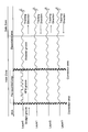
- FIG. 6 is a flowchart showing a procedure for performing test recording in a test recording area of a four-layer optical disc according to first to fourth embodiments of the present invention. It is a figure explaining the outline of the stack structure of the 4 layer optical disk by embodiment of this invention. It is a figure which shows the area
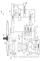
- FIG. 1 is a diagram showing a physical configuration of an optical disc 1 according to an embodiment of the present invention.
- A is a figure which shows the example of 25GB BD by embodiment of this invention
- (b) is a figure which shows the example of the optical disk of higher recording density than 25GB BD by embodiment of this invention. It is a figure which shows a mode that the light beam is irradiated to the mark row
- Non-Patent Document 1 also discloses an outline of the physical format of the Blu-ray Disc (BD) in the present embodiment.
- the information recording layer of a read-only optical disc in which a reflective film is formed on a substrate having uneven pits is combined with any one of an information recording layer of a write-once optical disc and an information recording layer of a rewritable optical disc.
- This technique is also common to so-called hybrid type multilayer optical information recording media.
- the physical structure of the optical disk medium is a multilayer optical disk in which information recording layers that can be recorded or read from the laser incident side are laminated in four layers with a track pitch of 0.32 ⁇ m, and the thickness from the laser incident surface to each information recording surface is
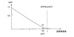
- a case will be described as an example in which recording is performed on the optical disc at 50 ⁇ m to 110 ⁇ m, the encoding method is 17PP modulation, and the shortest mark length (2T) is 0.112 ⁇ m to 0.124 ⁇ m, specifically 0.112 ⁇ m.
- the recording capacity per BD with a diameter of 12 cm corresponds to approximately 33.4 GB, and when this is stacked in three layers, approximately 100 GB and four layers are stacked. Corresponds to approximately 134 GB. Further, when recording is performed with a linear density at which the shortest mark length is 0.116 ⁇ m, the recording capacity per one surface of an optical disk having a diameter of 12 cm corresponds to approximately 32 GB, and when this is stacked in three layers, approximately 96 GB and four layers are stacked. This corresponds to approximately 128 GB.
- the recording capacity per surface of an optical disk having a diameter of 12 cm corresponds to approximately 30 GB, and when this is stacked in three layers, approximately 90 GB and four layers are stacked. This corresponds to approximately 120 GB.
- the linear velocity is 7.38 m / sec.
- the “OPC (Optimum Power Control) area” refers to performing test recording (also referred to as OPC) in an inner zone provided in the inner peripheral portion of the recording medium or an outer zone provided in the outer peripheral portion. An area allocated for this purpose.
- OPC Optimum Power Control
- “OPC (Optimum Power Control)” means a process of optimizing the recording power level of the laser beam irradiated on the optical disc during recording before recording data on the recordable optical disc. That is, when an optical disc is loaded on an optical recording / reproducing apparatus (optical disc apparatus), the optical disc apparatus repeatedly performs a process of performing test recording on the OPC area in the optical disc and reproducing the recorded signal, Calculate the optimal level. The recording power determined in this process is set as the optimum recording power, and when recording data, the recording operation is performed by irradiating the laser beam with the optimum recording power. Therefore, a test recording area is always provided for a recordable optical disc.
- the multilayer optical disc is used not only for the output power of the laser beam for recording the information recording layer in the back by the transmittance of the information recording layer in front, but also for each information recording layer as a recording film.
- Optimal recording conditions for each information recording layer (optimal recording power, optimal recording pulse conditions, etc.) due to differences in the composition of the recording material, the thickness of the recording film such as the recording film or protective layer, and the reflective layer Is different. Therefore, an OPC area for adjusting such recording conditions is required for all information recording layers.
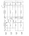
- FIG. 10 shows an area configuration on the plane of the multilayer optical disc medium 101.
- An inner zone 1004, a data area 1001, and an outer zone 1005 are arranged from the inner peripheral side of the optical disk medium.
- a PIC (Permanent Information & Control data) area 1003 and an OPC / DMA area 1002 are arranged.
- the OPC area is an area used for performing test recording and obtaining optimum recording power and recording pulse train conditions for the disc or each information recording layer before recording data in the data area 1001. Sometimes called a learning area.
- test recording is performed in order to adjust fluctuations in recording power and recording pulse trains when there are environmental variations such as individual variations of optical disk devices, sudden temperature fluctuations, and adhesion of dust and dirt. It is also an area.
- the PIC area 1003 is a reproduction-only area, and records disk management information by modulating the groove at high speed.
- Disc management information includes recommended values for OPC parameters, write strategy type, laser pulse generation timing and length (recording pulse conditions) necessary for obtaining optimum recording power, recording linear velocity, reproduction power, version Numbers are recorded.
- BCA Burst Cutting Area
- the data area 1001 is an area for actually recording data designated by the user on the optical disc, and is also called a user data area.
- In the outer zone there is no reproduction-only PIC area. Similar to the inner zone, an area for test recording and an OPC / DMA area related to management information of recording data are arranged.
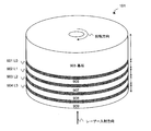
- FIG. 9 shows a schematic diagram of the stack structure of the four-layer optical disk medium of the present invention.
- the layer number starts from the 0th information recording layer instead of the first information recording layer.
- 905 is a substrate
- 901 is a 0th information recording layer L0 (L0 is abbreviated Layer 0)
- 902 is a first information recording layer L1
- 903 is a second information recording layer L2
- 904 is a third information recording layer L3.
- Reference numeral 909 denotes a cover layer, and laser light is incident from the cover layer side.
- the thickness of the substrate 905 is approximately 1.1 mm
- the thickness of the cover layer of 909 is at least 40 ⁇ m or more
- each information surface is separated by transparent space layers of 906, 907, and 908.
- the thickness of the cover layer 909 is 53 ⁇ m
- the thickness of the space layer between L3 and L2 is 12 ⁇ m
- the thickness of the space layer between L2 and L1 is 20 ⁇ m
- the space layer between L1 and L0 The thickness is 15 ⁇ m.
- the interval between the information recording layers separated by the space layer is preferably designed so that the interference of diffracted light from each information recording layer (interlayer interference) is reduced, and is limited to the interlayer distance depending on the thickness of the space layer described above. It is not done.
- FIG. 2 shows a cross section of the track layout of each layer of the four-layer optical disk of the present invention.
- the 0th information recording layer of the four-layer optical disk medium is formed by recording a unique ID unique to the medium called BCA in a format that burns out the information surface.
- BCA forms recording data in a bar code form by forming recording marks so as to be arranged concentrically. This is formed only at L0.
- the next area is the PIC area.
- information called disc management information or DI Disc Information
- Disc management information includes version number, layer number, maximum recording speed, write-once / rewritable disc type, recommended recording power for each information recording layer, various parameters required for OPC, recording pulse conditions, write strategy, copy Information used for protection is recorded.
- disc management information is recorded by wobbling a guide groove (Groove) formed in a spiral shape. These prerecorded information is read-only information that cannot be rewritten, and disc management information is recorded in advance by the disc manufacturer when the disc is manufactured. That is, the BCA and PIC areas are read-only areas.
- an OPC area and a disk management area (DMA) in which the optical disk apparatus performs test recording such as recording power and recording pulse conditions are provided.
- the OPC area is used for test recording in order to calibrate the fluctuations in recording power and recording pulse conditions at the time when the disc is inserted into the optical disc apparatus or when a certain temperature change occurs during operation. This is a test recording area to be performed.
- DMA Disc Management Area
- DMA is an area for managing disc management information and defect information.
- the radius of 24.0 mm to 58.0 mm is the data area.
- the data area is an area in which data desired by the user is actually written. In the data area, when there is a part that cannot be recorded / reproduced due to a defect in PC use etc., an ISA before and after the data area for recording / reproducing user data is used as a replacement area for replacing the part (sector, cluster) that cannot be recorded / reproduced. (Inner Space Area) and OSA (Outer Space Area) are set. In real-time recording that requires a high transfer rate, such as video recording / playback, the replacement area may not be set. From the radius of 58.0 mm, the outer periphery is the outer zone. The outer zone has the same OPC area and disk management area (DMA) as the inner zone. In addition, it is used as a buffer area so that overrun may occur during seek.
- DMA disk management area
- areas corresponding to the BCA are provided in the first to third information recording layers (L1 to L3), but the unique ID is not recorded. This is because even if BCA information such as a unique ID is newly recorded in the first to third information recording layers (L1 to L3), there is a possibility that reliable recording cannot be performed. Conversely, by not recording BCA except for L0, the reliability of BCA of L0 is improved.
- the read-only PIC area in which disc management information and the like are recorded in advance at the time of disc manufacture is arranged only on the 0th information plane (L0).
- FIG. 15 shows a cross section of the track layout of each layer of another four-layer optical disk of the present invention.
- the difference from the four-layer optical disk shown in FIG. 2 is that the read-only PIC area in which disk management information and the like are recorded in advance at the time of disk manufacture is changed from the 0th information plane (L0) to the 3rd information plane (L3). It is a point arranged in.
- the data of the individual information recording layers L0, L1, L2, and L3 can be distributed and recorded, so that the PIC information of any information recording layer is destroyed or deteriorated.
- the disc management information in the PIC area of another information recording layer can be read, and the reliability can be improved.
- the PIC area can be distributed and arranged in each information recording layer, the space of the PIC area of one information recording layer can be reduced, and the lead-in zone can be allocated to the OPC area accordingly. It can be used efficiently.
- FIG. 14 shows the usage direction of the cluster in the OPC area.
- the address order of the 0th information recording layer L0 and the second information recording layer L2 is recorded in the direction from the inner periphery to the outer periphery, and the recording / reproducing of the data area is performed from the inner periphery to the outer periphery according to the address order. Do in the direction.
- the address order of the first information recording layer L1 and the third information recording layer L3 is recorded from the outer periphery to the inner periphery, and the data area is recorded and reproduced from the outer periphery to the inner periphery.
- the full seek from the outer periphery to the inner periphery is not required, and the 0th information recording layer (L0) is changed from the inner periphery to the outer periphery, the first information recording layer (L1). ) Recording or reproduction can be performed sequentially from the outer periphery to the inner periphery and the inner layer to the previous layer, and real-time recording at a high transfer rate such as video recording and reproduction can be performed for a long time.
- L0 and L2 are used from the outer periphery to the inner periphery
- L1 and L3 are used from the inner periphery to the outer periphery.
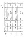
- FIG. 3 is a diagram showing an example of a physical format in which an OPC area is arranged in each information recording layer in the first embodiment of the present invention.
- FIG. 3 is a diagram showing an example of the physical format of the optical disk medium 101 having four information recording layers, particularly an arrangement of the OPC area.
- the zeroth information recording layer (L0) is located in the farthest information recording layer farthest from the laser beam incident side, and the first information recording layer (L1) is in front of the zeroth information recording layer. It is provided on the light incident side.
- second (L2) and third (L3) information recording layers are sequentially arranged on the laser beam incident side in order from the side closer to the first information recording layer.
- an inner zone, a data zone, and an outer zone are formed from the inner periphery according to the radial position.
- the inner zone of the 0th information recording layer is a read-only area formed at the time of disc creation, called a BCA area (Burst Cutting Area) and a PIC area (management data area) from the inner periphery. Control information).
- the area up to the PIC area is a read-only area, and the outer peripheral side of the PIC area is a recordable area.
- a second test recording area (OPC0-B area) for test recording conditions for recording and / or reproducing data, a DMA in which OPC area management information and the like are recorded, and a first test A recording area (OPC0-A area) is arranged.
- a protection area that is not written is provided as a buffer area, adjacent to the test recording area (OPC area).
- a buffer area In the inner zones of the first to third information recording layers, a buffer area, a second test recording area (OPC-B area), a DMA, and a first test recording area (OPC-A area) are arranged.
- the buffer area is a buffer area for mitigating interference between adjacent areas, and the protection means that writing means a write prohibited area is not performed.
- a region having a function as a region is provided.
- OPC0b, OPC1b, OPC2b, and OPC3b which are the second test recording areas (OPC-B areas) of the 0th to third information recording layers, are arranged on substantially the same radial position.
- the reason for being on substantially the same radial position is that when the information recording layers are stacked at the time of disc production, the error of the radial position of each layer cannot be accurately stacked to ⁇ 0 ⁇ m. Accordingly, it means that they are arranged on the same radial position including an error of an eccentric amount defined in advance.
- the first test recording areas (OPC-A areas) OPC0a, OPC1a, OPC2a, and OPC3a of the 0th to third information recording layers are arranged on approximately the same radial position.
- a data zone is located outside the inner zone, and user data is recorded in the data area of this zone.
- An outer zone is arranged outside the data zone and includes a third test recording area (OPCc area).
- OPC0c, OPC1c, OPC2c, and OPC3c are arranged in order from the 0th information layer to the 3rd information layer. Has been placed.
- OPC0c, OPC1c, OPC2c, and OPC3c which are the third test recording areas (OPC-C areas) of the zeroth to third information recording layers, are arranged on substantially the same radial position.
- a limited inner zone and outer zone are formed. It can be used effectively and the space efficiency can be improved.
- the four-layer disc of this embodiment even when the number of layers is increased to eight or sixteen layers, it is possible to secure a test recording area without increasing the physical size of the inner zone. That is, the test recording area can be secured without pressing the recording capacity of the data area.
- the physical size of the OPC area of each information recording layer should be larger in the limited inner zone or outer zone than when the test recording areas are arranged so as not to overlap each other.
- the recording power for test recording is not limited, and after starting the optical disk, parameters necessary for performing OPC from the PIC area are read and the first OPC is performed. It is an area. Until the optimum recording power is obtained by performing the OPC, there is no guarantee that the power level emitted from the laser is accurately emitted due to the variation or change with time of each optical disc apparatus. Alternatively, there may be a deviation from the recording power determined in advance at the time of manufacturing the disk due to the variation of each optical disk.
- the optimum recording power obtained by the combination of the apparatus and medium is recorded in a memory of the optical disk apparatus or a predetermined area of the optical disk medium.
- there are various factors such as dust and dirt adhering to the optical system parts of the optical pickup, fingerprints adhering to the disk, and the laser characteristics changing due to changes in the outside air temperature. It may happen that light is not emitted accurately at the recording power to be done.
- test recording is performed at a recording power higher than the optimum recording power as compared with the recording power appropriate for recording data. Even if test recording is performed using a history of test recording performed in the past using the same device and medium combination, even if the time has passed since the last recording, the optimum recording power Test recording may be performed with high recording power. If test recording is performed with excessive power in the OPC area of the front information recording layer, it is affected by intensity changes when the laser light passes through the front information recording layer, and the information recording layer in the back Then, it is considered that the optimum recording power cannot be derived by OPC. Specifically, there is a possibility that a deviation from the optimum recording power, a reproduction signal reading error, a tracking error signal or a focus error signal is distorted, and tracking or focus servo becomes unstable.
- the recording order between the layers in the OPC-A area is OPC-A in the order of the information recording layer farther from the laser light incident side and the information recording layer in the back to the front. It is assumed that the area will be used. Further, since the OPC-A area is arranged so as to overlap between the information recording layers, even if test recording is performed with excessive recording power, the OPC-A area in the back has already been test-recorded, or Since the innermost information recording layer has no inner information recording layer, even if recording is performed with an excessive recording power, the reproduction signal quality of the inner information recording layer is not adversely affected. .
- the OPC-B area is mainly used to obtain the timing and length conditions for generating a recording pulse train called write strategy adjustment using the optimum recording power obtained in the OPC-A area. Since the optimum value of the recording power is obtained in the same information recording layer in which the test recording is performed in the OPC-A area, there is no possibility of writing with an excessive recording power deviating from the optimum recording power.
- the recording power of the OPC-B area may be limited.
- test recording is performed with the optimum recording power obtained in the OPC-A area of the same information recording layer, or when the test recording is performed in the OPC-A area of a different information recording layer, Based on the optimum recording power obtained in the A area, an upper limit value of recording power that can be recorded at the time of test recording in the OPC-B area is set.
- the upper limit is based on a calculated value obtained by calculating a ratio between the optimum recording power obtained in the OPC-A area and the recommended recording power recorded in advance in the management data area determined at the time of manufacturing the disc. If the ratio of the difference between the optimum recording power and the recommended recording power is within a certain value, the upper limit value of the recording power for test recording in the OPC-B area is set based on the ratio. A specific description of how to obtain the upper limit will be described in detail in an embodiment described later.
- Table 1 summarizes the characteristics of the test recording areas (OPC-A area and OPC-B area) of two different categories as described above.
- the test recording area is divided into an area (OPC-A area) where the upper limit of the recording power at the time of test recording is not restricted and an area (OPC-B area) where the restriction is provided, and the upper limit recording power determined.
- a test recording area where test recording must be performed with the following recording power is defined as an OPC-B area, and an area in which no special limitation is imposed on the upper limit of recording power is defined as an OPC-A area.
- the inter-layer recording order of the OPC areas in the same section is limited in the OPC-A area, and is not limited in the OPC-B area.
- the order of recording between the layers in the OPC-A area is as follows. The test recording is performed sequentially from the test recording start point of the 0th information recording layer (L0) in which the OPC-A area is arranged at the innermost position. Do. After the L0 OPC-A area is used up, test recording is performed in the L1 OPC-A area of the previous information recording layer, and after the L1 OPC-A area is used up, the L2 OPC-A area is used. Recording is performed in order from the OPC-A area of the information recording layer arranged on the far side away from the laser beam incident side to the OPC-A area of the information recording layer on the front side, such as performing test recording in the area.
- test recording can be performed by moving to the OPC-B area of any information recording layer as necessary.
- writing to the OPC-B area with an excessive recording power is performed due to the restriction that the second and subsequent test recordings are performed on the OPC-B area or the upper limit of the recording power is provided. Therefore, random test recording in the OPC-B area is possible, and free recording between the information recording layers due to the defect management and file system management described above can be realized.
- the OPC-A area is arranged not only in L0 but also in the information recording layers from L1 to L3, even if the L0 OPC-A area is used up, the OPC-A areas from L1 to L3 are used in order. Even if the user data area of the write-once optical disk is empty, there is no possibility that the OPC area will be used up at an early stage, and it becomes impossible to write to the optical disk because test recording is not possible. It becomes possible to solve such problems.
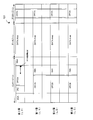
- FIG. 4 is a diagram showing an example of a physical format in which an OPC area is arranged in each information recording layer according to the second embodiment of the present invention.
- the difference from the multilayer optical disk of Embodiment 1 is that, in FIG. 4, a part of the OPC-B area from L1 to L3 is arranged to overlap with the PIC area of the 0th information recording layer, and the same In the information recording layer, the physical size of the OPC-B area is larger than the physical size of the OPC-A area.
- the OPC-B area is not written with an excessive recording power, when the L0 PIC area is reproduced, the light beam passing through the L1 to L3 OPC-B areas is scattered or diffracted. Accordingly, it is possible to suppress a decrease in reproduction signal quality when reproducing the PIC area.
- the OPC area can be arranged on the information recording layer in front of the PIC area, so that the physical area of the test recording area of each layer is limited within the limited physical size of the inner zone.
- the size can be increased, and the inner zone can be used efficiently.
- the OPC-A area is arranged not only in L0 but also in the information recording layers from L1 to L3, even if the L0 OPC-A area is used up, the OPC-A areas from L1 to L3 are used in order. Even if the user data area of the write-once optical disk is empty, there is no possibility that the OPC area will be used up at an early stage, and it becomes impossible to write to the optical disk because test recording is not possible. It becomes possible to solve such problems.
- the OPC-B area by increasing the size of the OPC-B area, it is possible to increase the number of test recordings for write strategy adjustment mainly performed in the OPC-B area.
- the write strategy adjustment must be performed more accurately by increasing the number of write strategy learning.
- the physical size of the OPC-B area is larger than the physical size of the OPC-A area in the same information recording layer, reliability can be improved without reducing the number of test recordings. High recording power adjustment and write strategy adjustment are possible.
- FIG. 5 is a diagram showing an example of a physical format in which an OPC area is arranged in each information recording layer according to the third embodiment of the present invention.
- L0 has one test recording area (OPC-A area).
- L1 to L3 are provided with two test recording areas, an OPC-A area and an OPC-B area.
- a part of the OPC-B area from L1 to L3 is arranged so as to overlap with the PIC area of L0. Since the OPC-B area is not written with an excessive recording power, when reproducing the PIC area of L0, the light beam passing through L1 to L3 is scattered and diffracted, and the PIC area A reduction in reproduction signal quality can be suppressed.
- the OPC-A regions from L1 to L3 are arranged so as to overlap substantially at the same radial position. Further, the physical size of the OPC-A area of L0 is larger than the physical size of each of the OPC-A areas of L1 to L3.
- the OPC area can be arranged on the information recording layer in front of the PIC area, so that the physical area of the test recording area of each layer is limited within the limited physical size of the inner zone.
- the size can be increased, and the inner zone can be used efficiently.
- the buffer area adjacent to the OPC area can be reduced compared to when two areas of the OPC-A area and the OPC-B area are provided.
- the number of the inner zones can be reduced, and the inner zone can be used more efficiently.
- the rear side of the OPC-A area of L1 to L3 is arranged.
- the inner zone can be used more efficiently.
- the physical size of the OPC-A area of L0 is larger than the physical size of the OPC-A area of L1 to L3.
- the probability that the OPC-A region is eliminated can be reduced. Learning at the time of activation can be increased at L0, and the activation time can be shortened.
- the OPC-A area is arranged not only in L0 but also in the information recording layers from L1 to L3, even if the L0 OPC-A area is used up, the OPC-A areas from L1 to L3 are used in order. Even if the user data area of the write-once optical disk is empty, there is no possibility that the OPC area will be used up at an early stage, and it becomes impossible to write to the optical disk because test recording is not possible. It becomes possible to solve such problems.
- FIG. 6 is a diagram showing an example of a physical format in which an OPC area is arranged in each information recording layer according to the fourth embodiment of the present invention.
- L0 has one test recording area (OPC-A area).
- L1 to L3 are provided with one test recording area of the OPC-B area.
- a part of the OPC-B area from L1 to L3 is arranged so as to overlap with the PIC area of L0. Since the OPC-B area is not written with an excessive recording power, when reproducing the PIC area of L0, the light beam passing through L1 to L3 is subjected to scattering and diffraction, and the reproduction signal quality of PIC Can be suppressed.
- the OPC-B regions from L1 to L3 are arranged so as to overlap substantially at the same radial position.
- the OPC area can be arranged in the information recording layer in front of the PIC area, so that the physical area of the test recording area of each layer is limited within the limited physical size of the inner zone.
- the size can be increased, and the inner zone can be used efficiently.
- the buffer area adjacent to the OPC area can be reduced compared to when two areas of the OPC-A area and the OPC-B area are provided.
- the number of the inner zones can be reduced, and the inner zone can be used more efficiently.
- the rear side of the OPC-B area of L1 to L3 is arranged.
- FIG. 7 is a diagram showing an example of a physical format in which an OPC area is arranged in each information recording layer according to the fifth embodiment of the present invention.
- L0 has one test recording area (OPC-A area).
- L1 to L3 are provided with two test recording areas, an OPC-A area and an OPC-B area.
- a part of the OPC-B area from L1 to L3 is arranged so as to overlap with the PIC area of L0. Since the OPC-B area is not written with an excessive recording power, when reproducing the PIC area of L0, the light beam passing through L1 to L3 is subjected to scattering and diffraction, and the reproduction signal quality of PIC Can be suppressed.
- the OPC-B regions from L1 to L3 are arranged so as to overlap substantially at the same radial position.
- the OPC-A regions from L1 to L3 are arranged so as to overlap substantially at the same radial position.
- the test recording can be started using the OPC-A areas provided in the two information recording layers L0 and L1.
- the L1 to L3 information recording layers must be semi-transparent layers that transmit light to the back information recording layer in designing the recording film, but there is a restriction on the L0 information recording layer. Absent. That is, the configuration of the recording material and the recording film of the information recording layer is greatly different between L0 and L1 to L3.
- the first test recording is performed not only in the OPC-A area of L0 but also in the two OPC-A areas of the OPC-A area of L1. If the upper limit value of the recording power when performing the test recording of L2 and L3 based on the optimum recording power obtained by L1 is the same recording film characteristic, the optimum recording of L2 and L3 It becomes possible to obtain power more accurately.
- the OPC-A area is arranged not only in L0 but also in the information recording layers from L1 to L3, even if the L0 OPC-A area is used up, the OPC-A areas from L1 to L3 are used in order. Even if the user data area of the write-once optical disk is empty, there is no possibility that the OPC area will be used up at an early stage, and it becomes impossible to write to the optical disk because test recording is not possible. It becomes possible to solve such problems.
- FIG. 17 is a diagram showing another example of a physical format in which an OPC area is arranged in each information recording layer according to the fifth embodiment of the present invention.
- L0 is provided with two test recording areas (OPC-A areas).
- L1 to L3 are provided with two test recording areas, an OPC-A area and an OPC-B area. Part of the OPC-A area from L1 to L3 is arranged so as to overlap with the PIC area of L0. In addition, the OPC-A regions from L1 to L3 are roughly overlapped.
- the OPC-A area from L1 to L3 may be written with an excessive recording power, but a buffer area corresponding to the adjacent area of the OPC-A area from L1 to L3 is secured.
- a PIC area is also secured in L0 on the far side. Therefore, when reproducing the PIC area of L0, the light beam passing through L1 to L3 is scattered and diffracted.
- the PIC area arranged on the far side of the buffer area it is possible to suppress degradation of the reproduction signal quality. it can.
- the disc management data of each information recording layer is recorded in the block unit in the PIC area, and the unit block is repeatedly recorded in the PIC area a plurality of times. Therefore, it is not necessary to read the disk management data in all areas of the PIC area. That is, there is no problem as long as the disk management data of at least one block among a plurality of repeatedly recorded blocks can be read.
- the disk management data in the PIC area on the back side of the buffer areas L1 to L3 may be read without any problem.
- the PIC area is arranged on the back side of the L1 to L3 OPC area, and the buffer area is provided adjacent to the L1 to L3 OPC area so that the space in the lead-in zone can be efficiently reduced. It is possible to secure a sufficient OPC area for use.
- the PIC area is a reproduction-only area, and disc management information is recorded by modulating the groove at high speed.
- the track pitch (0.35 ⁇ m) of the PIC area is wider than the track pitch (0.32 ⁇ m) of the data area, the data read reliability is originally designed to be high. Therefore, even if test recording is performed with an excessive recording power in the L1 to L3 OPC-A areas arranged in front of the PIC area, the deterioration in the reading performance of the disc management information recorded in the PIC area is additionally recorded.
- the reading reliability is designed to be higher than that in the case where read data or rewritable data is read.
- the PIC area of L0 and the OPC-A areas of L1 to L3 are arranged so as to overlap, the reliability at the time of reading the disc management information recorded in the PIC area is not greatly impaired.
- the OPC-B region from L1 to L3 and the OPC-A region from L0 are arranged so as to overlap substantially at the same radial position. Further, the OPC-A regions from L1 to L3 are arranged so as to overlap substantially at the same radial position. In this way, using the OPC-A areas provided in the two information recording layers L0 and L1, it is possible to use the OPC-A area with the two points L0 and L1 as test recording start points. .
- the L1 to L3 information recording layers must be semi-transparent layers that transmit light to the back information recording layer in designing the recording film, but there is a restriction on the L0 information recording layer. Absent.
- the configuration of the recording material and the recording film of the information recording layer is greatly different between L0 and L1 to L3.
- the recording films have different properties in L0 and L1 to L3, the first test recording is performed not only in the OPC-A area of L0 but also in the two OPC-A areas of L0 and L1. If L2 and L3 are characteristics of similar recording films, it is best to obtain the upper limit value of the recording power when performing test recording of L2 and L3 based on the optimum recording power obtained in L1. It becomes possible to obtain the recording power with higher accuracy.
- the OPC-A area is arranged not only in L0 but also in the information recording layers from L1 to L3, even if the L0 OPC-A area is used up, the OPC-A areas from L1 to L3 are used in order. Even if the user data area of the write-once optical disk is empty, there is no possibility that the OPC area will be used up at an early stage, and it becomes impossible to write to the optical disk because test recording is not possible. It becomes possible to solve such problems.
- the OPC-A area is divided into two in L0 in FIG. 17, one may be an OPC-B area, or the arrangement of the OPC areas in L0 may be changed and combined into one OPC-A area. . By combining them into one, it is not necessary to provide a buffer area, and the space efficiency of the lead-in area is improved.
- connection zone between the HFM groove and the wobble groove can be used as the buffer area, improving the space efficiency of the lead-in area. To do.
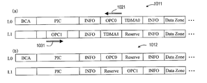
- FIG. 18A shows a write-once disc 1011 having two information recording layers
- FIG. 18B shows a rewritable disc 1012 having two information recording layers.
- buffer areas and the like are arranged in some places to absorb eccentricity and interference from adjacent areas, but the description thereof is omitted here for convenience.
- the track direction (light spot traveling direction) of the layer (L0) far from the light source is from the inner circumference side to the outer circumference side.
- the direction is the direction from the left side to the right side in FIG.
- the track direction of the layer (L1) closer to the light source is the direction from the outer peripheral side to the inner peripheral side (the direction from the right side to the left side in FIG. 18) (opposite path).
- OPC0 which is a test recording area in the L0 layer
- OPC1 which is a test recording area in the L1 layer, do not overlap in radial position.
- the PIC area is arranged in the L0 layer and is not arranged in the L1 layer.
- OPC1 is arrange
- OPC0 is arrange
- the usage direction 1021 of OPC0 is the direction from the outer peripheral side region in OPC0 to the inner peripheral side region in OPC0
- the usage direction 1031 in OPC1 is the outer peripheral region in OPC1 from the inner peripheral side region in OPC1. The direction of the side area.
- the PIC area is arranged in both the L0 layer and the L1 layer, and the OPC0 is arranged at a radial position on the inner peripheral side of the OPC1. Further, the usage direction of the OPC is not restricted like the write-once optical disc 1011.
- TDMA Temporal Disc Management Area
- the final defect information of TDMA is recorded in the DMA in the INFO area.
- the Next Available PSN information described above is different from the defect information and is information necessary for managing the OPC. Therefore, although it is recorded in the TDMA, since test recording is not executed after the finalization, there is no need to manage it, so it is not recorded in the DMA in the INFO area.
- the information managed by the TDMA is much larger than the information recorded in the DMA in the INFO area.
- the DMA in the INFO area is 32 blocks, and each TDMA has 2048 blocks. A sufficient size is secured.
- the relationship between TDMA0 and TDMA1 is used in the order of TDMA0 to TDMA1. That is, when recording to TDMA0 becomes impossible due to a decrease in the free area of TDMA0 in the L0 layer or the like, update processing in TDMA1 in the L1 layer is performed.
- the rewritable disc can be updated by rewriting, such defect information is updated using the DMA in the INFO area.
- an area at a radial position substantially corresponding to TDMA0 or TDMA1 in the write-once disc is secured as a reserved area whose usage is not particularly determined. Therefore, in the description up to FIG. 17, in the case of a rewritable disc, the area described as DMA does not necessarily have to be DMA, and may be a reserved area.
- the read-only management data area for example, PIC area
- the test recording area for example, OPC area
- the size of the OPC area is kept large while minimizing the configuration in which the OPC areas are arranged at the same radial position. This can reduce the possibility of using up the OPC area. Since the same information is repeatedly recorded in the PIC area, even if those OPC areas are damaged by the laser beam, the information is surely received from the part of the PIC area that does not overlap the damaged OPC area. Can be read out.
- the read-only management data area for example, PIC area
- the write-inhibited area for example, buffer area
- the laser beam is not damaged. Therefore, information can be reliably read from the portion of the PIC area that overlaps the buffer area. If an area on another layer that overlaps a part of the PIC area (for example, the OPC area) is damaged, information may not be read from the corresponding part of the PIC area.
- the information can be reliably read from the portion of the PIC area overlapping the buffer area.
- disk management data of each information recording layer is recorded in units of blocks, and unit blocks are repeatedly recorded in the PIC area a plurality of times. Therefore, the disk management data in almost all areas of the PIC area may be damaged due to the influence of writing in the previous layer and become unreadable. That is, there is no problem as long as the disk management data of at least one block among a plurality of repeatedly recorded blocks can be read.
- the disk management data in the PIC area on the back side of the buffer areas L1 to L3 may be read without any problem.
- the PIC area is arranged on the back side of the L1 to L3 OPC area, and the buffer area is provided adjacent to the L1 to L3 OPC area so that the space in the lead-in zone can be efficiently reduced. It is possible to secure a sufficient OPC area for use.
- an information recording layer in which an OPC area is arranged on the outer peripheral side instead of the inner peripheral side of DMA (TDMA).
- DMAs are divided and arranged on the inner and outer peripheral sides of the OPC area. That is, by providing two management data areas (for example, TDMA areas) that can be recorded in one information recording layer on the inner peripheral side and the outer peripheral side of the OPC area, the OPC areas of the other information recording layers and the OPC areas The amount of overlap between layers can be reduced or eliminated.
- a recordable management data area for example, a TDMA area
- the OPC areas must be overlapped with each other, but the recordable management data area is located on the inner circumference side.
- the outer two are divided into two, and the size of the OPC area and the recordable management data area is both large while minimizing the configuration in which the OPC areas are arranged at the same radial position. be able to. This can reduce the possibility that the OPC area and the recordable management data area will be used up.
- the buffer area adjacent to the OPC area must be increased in proportion to the OPC area.
- the buffer area is buffered in the adjacent portion. Since it is not necessary to provide an area, the lead-in zone can be used effectively.
- TDMA DMA-to-DMA
- a management data area for example, DMA (TDMA)
- a management data area for example, DMA (TDMA)
- a management data area for example, DMA (TDMA)
- an information recording layer including a plurality of DMAs (TDMA).
- TDMA DMAs
- the amount of overlap between the OPC areas between the OPC areas of other information recording layers is reduced, or Can be eliminated.
- a recordable management data area for example, a TDMA area
- the OPC areas must be placed one on top of the other, but the two recordable management data areas are sandwiched between the OPC areas.
- the buffer area adjacent to the OPC area must be increased in proportion to the OPC area.
- the buffer area is buffered in the adjacent portion. Since it is not necessary to provide an area, the lead-in zone can be used effectively.
- an information recording layer that includes two DMAs (TDMA) and an OPC area is arranged between the TDMAs.
- the OPC area can be arranged at a position away from the user data area.
- the OPC region of the information recording layer far from the laser irradiation surface and the DMA (TDMA) of the information recording layer near the laser irradiation surface may overlap each other in radial position. In this case, even if the OPC region of the information recording layer far from the laser irradiation surface is damaged by the laser beam, information can be read out from the DMA (TDMA) of the information recording layer near the laser irradiation surface without any problem. . Further, when the OPC area is arranged inside the DMA (TDMA), the remaining zone whose size is limited can be used effectively.
- FIG. 17 there is an information recording layer in which write-inhibited areas (such as buffer areas) are arranged at both ends of the OPC area.
- a first buffer area is arranged adjacent to the inner peripheral side of the OPC area.
- a second buffer area is arranged adjacent to the outer peripheral side of the OPC area.
- a first DMA (TDMA) is disposed adjacent to the inner periphery of the first buffer area, and a second DMA (TDMA) is disposed adjacent to the outer periphery of the second buffer area.
- Information of the same attribute is recorded in the first and second DMAs (TDMA). That is, when an OPC area is arranged between two DMAs (TDMA), a buffer area is arranged between the DMA (TDMA) and the OPC area.
- the management data area that can be recorded across the OPC area is divided into two, and the OPC area and the OPC area can be recorded while minimizing the configuration in which the OPC areas are arranged at the same radial position. It is possible to secure a large size for both the management data area and reduce the possibility that the OPC area and the recordable management data area will be used up. Conversely, if the OPC area is divided and arranged, the buffer area adjacent to the OPC area must be increased in proportion to the OPC area. However, when the recordable management data area is divided and arranged, the buffer area is buffered in the adjacent portion. Since it is not necessary to provide an area, the lead-in zone can be used effectively.
- the information recording medium of the present invention does not have to satisfy all of the above-described features shown in FIG. 17, and may have a configuration that employs any one of these features, or a configuration that arbitrarily combines a plurality of features. Good.
- the first step is to read the disc management information in the PIC area and the OPC management information recorded in the DMA.
- Recommended recording power of each information recording layer pre-recorded in the PIC area, various parameters necessary for OPC, write strategy parameter, position of the OPC area of each information recording layer recorded in the DMA, eg, recording start address and / or Alternatively, information indicating the end address and Next Available PSN (Physical Sector Number) which is information indicating the currently available position in each OPC area are read.
- the OPC area management information of the DMA is read, the position of the OPC area in the optical disk and the position in the usable OPC area are confirmed from this information, and the confirmed position OPC can be performed.
- the process proceeds to the next step. If all the OPC-A areas are used up, the test recording becomes impossible and the test recording is stopped.
- the second step is a step in which test recording is performed in the OPC-A area of the i-th information recording layer to obtain an optimum value of recording power.
- test recording is performed with a plurality of recording powers using the OPC parameters read from the PIC area, the modulation degree characteristics of the recorded signals are measured, and predetermined results are obtained based on the results.
- An optimum recording power is obtained by performing calculation. A method for obtaining the optimum recording power from the measurement result of the modulation degree will be described in an embodiment described later.
- the optimum recording power obtained in the OPC-A area is the optimum recording power that should originally be obtained.
- the optimum recording power (Pwoi) obtained in the OPC-A area in the operation procedure for obtaining the optimum recording power described above, and the recommended recording power (Pwpi) read from the disc management information recorded in advance in the PIC area of the optical disc When the optimum recording power (Pwoi) is larger than the recommended recording power (Pwpi), for example, by more than 5% (Pwoi / Pwpi-1> 5%), the obtained optimum recording power (Pwoi) ) Is determined to be inappropriate and the write strategy is changed again, or the above-described OPC procedure is performed again with the write strategy as it is, and the optimum recording power (Pwoi) is obtained again.
- the optimum recording power obtained in the OPC-A area using the optical disc apparatus in the operation procedure for obtaining the optimum recording power described above is the recording power originally assumed by the optical disc manufacturer at the time of disc creation.
- the optimum modulation power and the target modulation degree (Mmax) of the recommended recording power read from the disc management information pre-recorded in the PIC area on the optical disc are
- the modulation degree at the time of recording at the optimum recording power is larger than the target modulation degree (Mmax) (Mo> Mmax) compared with the modulation degree (Mo) of the signal recorded at the recording power
- the optimum obtained It is determined that the recording power (Pwoi) is high, and the write strategy is changed again, or the write In ⁇ °, again the above OPC procedure, again determine the optimum recording power (Pwoi).
- the modulation degree (Mo) recorded at the optimum recording power is compared with the target modulation degree (Mmax), and the modulation degree at the time of recording at the optimum recording power is equal to the target modulation degree (Mmax).
- the obtained optimum recording power (Pwoi) is determined as the optimum recording power.
- the above example has been described as the method for checking the optimum recording power, the above methods may be combined, or the check may be performed by another suitable method.
- jitter, MLSE, ⁇ , asymmetry, etc. may be used in combination for the determination material.
- the third step is a step for making preparations for performing test recording on the j-th layer which is an information recording layer other than the i-th layer.
- the optimum recording power (Pwyj) predicted for the information recording layer of j is calculated by the following equation.
- (Pwyj) (Pwpj) ⁇ ⁇
- the ratio ⁇ is a ratio between the optimum recording power obtained by the test recording and the recommended recording power. That is, an index indicating how much the recording power set by the optical disk apparatus due to dust, dust, or other causes in the optical disk apparatus is the absolute value of the recording power relative to the recording power determined by the disk manufacturer when the optical disk was created. It is.
- the optimum recording power obtained matches the recommended recording power, and the recording power obtained by test recording using the optical disc apparatus was recorded in advance by the disc manufacturer at the time of disc creation. It means that it matches the power.
- ⁇ > 1 as an example, dust, dust, etc. adhere to an optical system of an optical disk device, for example, an objective lens. Between the recording power immediately after the laser beam is emitted on the way and the recording power on the optical disk board surface Occurs when there is a loss. Or, there may be an error in the calibration of the recording power of the optical disc apparatus. If these are the causes, the same recording power loss and calibration error also occur in the other information recording layers. Therefore, the recording power set by the optical disk device and the actual information recording of the optical disk using the ratio ⁇ . The purpose is to correct between the irradiation power on the surface.
- the fourth step is a step of performing test recording in the OPC-B area of the j-th information recording layer to obtain the optimum recording power and recording pulse condition of the j-th layer.
- test recording is performed with a plurality of recording powers equal to or lower than the upper limit recording power (Pwmaxj) determined in the third step, the modulation characteristic of the recorded signal is measured, and the jth information recording is performed.
- the optimum recording power (Pwoj) of the layer is obtained.
- test recording is performed on the OPC-B area of the jth information recording layer with the optimum recording power (Pwoj), and the recording pulse condition (write strategy condition) Find the optimal value.
- the test recording on the jth information recording layer is completed.
- a processing procedure for checking whether or not the obtained optimum recording power (Pwoj) is the optimum recording power that should be originally obtained may be inserted.
- the fifth step is a step for checking whether or not the test recording of all information recording layers has been completed. If the test recording has not been completed for all the information recording layers, the process returns to the fourth step to perform the test recording for the remaining information recording layers to obtain the optimum values of the recording power and the write strategy. If test recording has been completed for all information recording layers, test recording completion processing is performed. That is, the DMA Next Available PSN information is updated and the test recording is completed.
- X 1.1 as an example.
- the upper limit value of the recording power may be updated to an appropriate value. However, test recording cannot be performed beyond the previously determined upper limit power until the optimum power is obtained.
- the recording method is described in the embodiment of the present invention, it is because the procedure of the recording operation is mainly described, and is not necessarily limited to the recording operation, and includes the optical recording / reproducing method including the reproducing method. May be.
- the first step is to read the disc management information in the PIC area and the OPC management information recorded in the DMA.
- Recommended recording power of each information recording layer pre-recorded in the PIC area, various parameters necessary for OPC, write strategy parameter, position of the OPC area for each information recording layer recorded in the DMA, eg, recording start address and Next, information indicating the end address and Next Available PSN (Physical Sector Number), which is information indicating the currently usable position in each OPC area, are read.
- the OPC area management information of the DMA is read, the position of the OPC area in the optical disk and the position in the usable OPC area are confirmed from this information, and the confirmed position OPC can be performed.
- the process proceeds to the next step. If the OPC-A area of the 0th layer has been used up or if all the OPC-A areas have been used up, test recording is disabled and test recording is stopped. If the OPC-A area of the 0th information recording layer can be recorded and the first to third OPC-A areas are used up, test recording is performed according to the procedure of the sixth embodiment.
- the second step is a step in which test recording is performed in the OPC-A area of the 0th information recording layer to obtain the optimum value of the recording power.
- test recording is performed with a plurality of recording powers using the OPC parameters read from the PIC area, the modulation degree characteristics of the recorded signals are measured, and predetermined results are obtained based on the results.
- An optimum recording power is obtained by performing calculation. Further, test recording is performed with the optimum power, and the optimum recording pulse condition (write strategy condition) of the 0th layer is obtained. Thus, the test recording on the 0th information recording layer is completed.
- a method for obtaining the optimum recording power from the measurement result of the modulation degree will be described in an embodiment described later.
- the third step is a step in which test recording is performed in the OPC-A area of the i-th information recording layer to obtain an optimum value of recording power.
- test recording is performed with a plurality of recording powers using the OPC parameters read from the PIC area, the modulation characteristics of the recorded signals are measured, and predetermined results are obtained based on the results. To obtain the optimum recording power.
- the optimum recording power (Pwoi) obtained in the OPC-A area of the i-th information recording layer in the operation procedure for obtaining the optimum recording power and the disc management information recorded in advance in the PIC area of the optical disc are read.
- the recommended recording power (Pwpi) is compared, and when the optimum recording power (Pwoi) is, for example, 5% or more larger than the recommended recording power (Pwpi) (Pwoi / Pwpi-1 ⁇ 5%), The optimum recording power (Pwoi) is determined to be inappropriate, and the write strategy is changed again, or the above-described OPC procedure is performed again using the write strategy as it is, and the optimum recording power (Pwoi) is obtained again.
- the optimum recording power obtained in the OPC-A area using the optical disc apparatus in the operation procedure for obtaining the optimum recording power described above is the recording power originally assumed by the optical disc manufacturer at the time of disc creation.
- the optimum modulation power and the target modulation degree (Mmax) of the recommended recording power read from the disc management information pre-recorded in the PIC area on the optical disc are When the modulation degree at the time of recording at the optimum recording power is larger than the target modulation degree (Mmax) (Mo> Mmax) compared with the modulation degree (Mo) of the signal recorded at the recording power, the optimum obtained It is judged that the recording power (Pwoi) is high and the write strategy is changed again, or the write power is kept as it is.
- test recording is performed with the optimum power in the OPC-B area of the i-th layer, and the optimum recording pulse condition (write strategy condition) of the i-th layer is obtained. This completes test recording on the i-th layer.
- the above example has been described as the method for checking the optimum recording power, the above methods may be combined, or the check may be performed by another suitable method.
- jitter, MLSE, ⁇ , asymmetry, etc. may be used in combination for the determination material.
- the fourth step is a step for preparing to perform test recording on the j-th layer, which is an information recording layer other than the i-th layer.
- the optimum recording power (Pwyj) predicted for the information recording layer of j is calculated by the following equation.
- (Pwyj) (Pwpj) ⁇ ⁇
- the ratio ⁇ is a ratio between the optimum recording power obtained by the test recording and the recommended recording power. That is, an index indicating how much the recording power set by the optical disk apparatus due to dust, dust, or other causes in the optical disk apparatus is the absolute value of the recording power relative to the recording power determined by the disk manufacturer when the optical disk was created. It is.
- the optimum recording power obtained matches the recommended recording power, and the recording power obtained by test recording using the optical disc apparatus was recorded in advance by the disc manufacturer at the time of disc creation. It means that it matches the power.
- ⁇ > 1 as an example, dust, dust, etc. adhere to an optical system of an optical disk device, for example, an objective lens. Between the recording power immediately after the laser beam is emitted on the way and the recording power on the optical disk board surface Occurs when there is a loss. Alternatively, there may be an error in calibration of the recording power of the optical disc apparatus. If these are the causes, the same recording power loss and calibration error also occur in the other information recording layers. Therefore, the recording power set by the optical disk device and the actual information recording of the optical disk using the ratio ⁇ . The purpose is to correct between the irradiation power on the surface.
- the fifth step is a step of performing test recording in the OPC-B area of the j-th information recording layer to obtain the optimum recording power and recording pulse condition of the j-th layer.
- test recording is performed with a plurality of recording powers less than or equal to the upper limit recording power (Pwmaxj) determined in the fourth step, the modulation characteristic of the recorded signal is measured, and the jth information recording The optimum recording power (Pwoj) of the layer is obtained.
- test recording is performed on the OPC-B area of the jth information recording layer with the optimum recording power (Pwoj), and the recording pulse condition (write strategy condition) Find the optimal value.
- the test recording on the jth information recording layer is completed.
- a processing procedure for checking whether or not the obtained optimum recording power (Pwoj) is the optimum recording power to be originally obtained may be inserted.
- the sixth step is a step for checking whether or not the test recording of all information recording layers has been completed. If the test recording has not been completed for all the information recording layers, the process returns to the fifth step to perform test recording for the remaining information recording layers to obtain the optimum values of the recording power and the write strategy. If test recording has been completed for all information recording layers, test recording completion processing is performed. That is, the DMA Next Available PSN information is updated and the test recording is completed.
- X 1.1 as an example.
- the upper limit value of the recording power may be updated to an appropriate value. However, test recording cannot be performed beyond the previously determined upper limit power until the optimum power is obtained.
- the recording method is described in the embodiment of the present invention, it is because the procedure of the recording operation is mainly described, and is not necessarily limited to the recording operation, and includes the optical recording / reproducing method including the reproducing method. May be.
- the apparatus 100 is an apparatus that performs at least one of recording and reproduction of information with respect to the information recording medium 101, and may be a reproduction-only apparatus.
- FIG. 1 is a diagram for explaining the overall configuration of a recording / reproducing apparatus for a multilayer optical information recording medium according to an eighth embodiment of the present invention. An operation of performing test recording and performing test recording on each information recording layer using the multilayer optical discs of Embodiments 1 to 5 and the recording methods of Embodiments 6 and 7 will be described.
- the multilayer optical disc 101 is a multilayer optical information recording medium such as a BD-R medium.
- the recording / reproducing apparatus 100 includes an optical pickup 111, a spindle motor 122, and a servo control unit 112.
- the optical pickup 111 includes a diffraction element 102, collimating lenses 103 and 104, an objective lens 105, a laser light source 106, an actuator 107, photodetectors 109 and 110, and a servo control unit 112.
- the recording / reproducing apparatus 100 includes a recording unit that reproduces management data from a management data area (PIC, DMA, TDMA, etc.) and records information on an information recording medium based on the management data.
- the recording unit includes a spherical aberration correction unit 108, an RF signal calculation unit 113, a laser drive circuit 114, a laser output control circuit 115, a recording power control unit 116, a reproduction signal detection unit 117, and a management information reading unit. 118, a calculation unit 119, a memory 120, and a system control unit 121.
- the recording unit also adjusts the recording conditions using the test recording area, and performs an operation of recording information on the multilayer optical disc 101 under the adjusted recording conditions.
- An optical pickup 111 including a laser light source 106 and photodetectors 109 and 110 functions as an irradiating unit that irradiates each information recording layer of the multilayer optical disc 101 with laser light and receives reflected light reflected by the information recording layer. Functions as a light receiving unit.
- the RF signal calculation unit 113, the reproduction signal detection unit 117, the management information reading unit 118, the calculation unit 119, the memory 120, and the system control unit 121 reproduce the information based on the electrical signal obtained by receiving the reflected light. It functions as a part.
- the light beam emitted from the laser light source 106 is converted into parallel light by the collimating lenses 103 and 104, enters the objective lens 105, and is converged on the information recording surface of the multilayer optical disc 101.
- the light beam reflected by the multilayer optical disc 101 travels back along the original optical path and is collected by the collimating lenses 103 and 104, and enters the photodetectors 109 and 110 by the light branching means of the diffraction element 102.
- Servo signals focus error signal and tracking error signal
- information signal RF signal
- the actuator 107 performs focus control, which is position control of the objective lens 105 in the optical axis direction, and tracking control, which is position control perpendicular to the direction in which the objective lens 105 is perpendicular to the traveling direction of the light beam, by the servo control unit 112. It is controlled by driving a driving means such as a magnet. Further, the RF signal calculation unit 113 generates an RF signal.
- the spherical aberration correction unit 108 drives the collimating lens 104 to perform optimal spherical aberration correction according to the thickness from the surface of each information layer.
- a laser drive circuit 114 that drives the laser light source 106 in the optical pickup 111, a laser output control circuit 115 that controls the laser drive circuit 114 with a desired laser output, and a plurality of recording powers in the laser output control circuit
- a recording power control unit 116 for issuing a test recording, data recording or reproduction instruction, and a reproduction signal detection unit for detecting the signal quality (modulation, asymmetry, ⁇ , jitter, MLSE, etc.) of the reproduction signal from the RF signal 117, a management information reading unit 118 that reads out the disc management information of the PIC area and the OPC area management information of the DMA recorded on the multilayer optical disc 101 from the RF signal, reproduces the test recorded signal, and reproduces the signal
- the optimum recording power is calculated from the modulation degree characteristic detected in step 1, and the optimum recording power is calculated.
- the system control unit 121 sets predetermined recording conditions in the recording power control unit based on the read information of the management information reading unit.
- the system control unit issues a command to the recording power control unit 116 and repeats the test recording operation until the test recording of all the information recording layers is completed.
- a light beam emitted from a laser light source 106 driven by a laser driving circuit 114 moves through a collimating lens 104 by a spherical aberration correction unit 108, and is a multilayer optical information recording medium (BD-R medium).
- the light is condensed on a desired information recording layer of the multilayer optical disc 101.
- the servo control unit 112 controls focus and tracking of the light spot on a desired information recording layer.
- the optical pickup 111 seeks to the inner periphery of the multilayer optical disc 101 and reads disc management information (DI: Disc Information) in the PIC area.
- DI disc Management Information
- the system control unit 121 sets a plurality of powers within a range of ⁇ 10% in the vicinity of the target recording power (Pind), which is one of the OPC parameters in the DI information, and performs test recording a plurality of times while changing the recording power.
- the recording power control unit 116 is instructed.
- the laser output control circuit 115 applies power servo so as to emit light at a desired recording power, and the laser drive circuit 114 drives the laser light source 106, and a light beam focused by the objective lens 105 is used to generate a desired test recording area. A signal is recorded on a desired track (or desired cluster).
- FIG. 12 shows a reproduction signal when a signal including an 8T signal is recorded. The upper side of FIG.
- the reproduction signal detection unit 117 detects the voltage levels (I8H, I8L) of the 8T space which is the longest space and the 8T mark which is the longest mark from the RF signal.
- the calculation unit 119 calculates a modulation degree (MOD) from the voltage level (I8H, I8L) detected by the reproduction signal detection unit 117.
- the computing unit 119 calculates the product (MOD ⁇ Pw) of the modulation power (MOD) and the recording power (Pw) at the recording power (Pw) from the measurement result of the modulation power for a plurality of test recording powers.
- FIG. 13 shows an example of a diagram for explaining the product (MOD ⁇ Pw) of the modulation degree and the recording power with respect to the recording power.
- a tangent line 1301 is drawn and the intercept with the x-axis (power axis) is defined as the limit recording power (Pth).
- the optimum recording power (Pwo) is calculated using the limit recording power (Pth) and the power multiplication factors ⁇ and ⁇ .
- ⁇ , ⁇ , and Pind are the OPC parameters, and the result of reading out those recorded in advance in the disk management area is used.
- the calculation unit checks whether or not the optimum recording power obtained in the OPC-A area is the optimum power that should be obtained originally.
- the recommended recording power (Pwpi) of the i-th layer is compared, and when the optimum recording power is, for example, 5% or more larger than the recommended recording power (Pwpi) (Pwoi / Pwpi-1 ⁇ 5%) It is determined that the recording power (Pwoi) is inappropriate, and the write strategy is changed again, or the above-described OPC procedure is performed again with the write strategy as it is, and the optimum recording power (Pwoi) is obtained again.
- the optimum recording power obtained in the OPC-A area using the optical disc apparatus in the operation procedure for obtaining the optimum recording power described above is the recording power originally assumed by the optical disc manufacturer at the time of disc creation.
- the optimum modulation power and the target modulation degree (Mmax) of the recommended recording power read from the disc management information pre-recorded in the PIC area on the optical disc are When the modulation degree at the time of recording at the optimum recording power is larger than the target modulation degree (Mmax) (Mo> Mmax) compared with the modulation degree (Mo) of the signal recorded at the recording power, the optimum obtained It is judged that the recording power (Pwoi) is high and the write strategy is changed again, or the write power is kept as it is.
- the above example has been described as the method for checking the optimum recording power, the above methods may be combined, or the check may be performed by another suitable method.
- jitter, MLSE, ⁇ , asymmetry, etc. may be used in combination for the determination material.
- the method of obtaining the optimum value of the recording power by measuring the modulation degree of the signal recorded with a plurality of recording powers has been described.
- the method of obtaining the optimum power is a method of obtaining from the modulation degree.
- a method may be used in which one or more of other signal indicators such as ⁇ , jitter, asymmetry, and MLSE are measured and measured.
- the product of the nth power of the recording power of the modulation degree is used.
- the optimum value of the recording power may be obtained using the n ⁇ ⁇ method.
- the ratio ⁇ is a ratio between the optimum recording power obtained by the test recording and the recommended recording power. That is, an index indicating how much the recording power set by the optical disk apparatus due to dust, dust, or other causes in the optical disk apparatus is the absolute value of the recording power relative to the recording power determined by the disk manufacturer when the optical disk was created. It is.
- the optimum recording power obtained matches the recommended recording power, and the recording power obtained by test recording using the optical disc apparatus was recorded in advance by the disc manufacturer at the time of disc creation. It means that it matches the power.
- ⁇ > 1 as an example, dust, dust, etc. adhere to an optical system of an optical disk device, for example, an objective lens. Between the recording power immediately after the laser beam is emitted on the way and the recording power on the optical disk board surface Occurs when there is a loss. Or, there may be an error in the calibration of the recording power of the optical disc apparatus. If these are the causes, the same recording power loss and calibration error also occur in the other information recording layers. Therefore, the recording power set by the optical disk device and the actual information recording of the optical disk using the ratio ⁇ . The purpose is to correct between the irradiation power on the surface.
- the system control unit 121 instructs the recording power control unit 116 to perform test recording in the OPC-B area of the j-th information recording layer and obtain the optimum recording power and recording pulse condition of the j-th layer.
- test recording is performed with a plurality of recording powers equal to or less than the upper limit recording power (Pwmaxj), and the reproduction signal detection unit 117 determines the modulation degree characteristic of the reproduction signal of the RF signal output from the RF signal generation unit 113. taking measurement.
- the calculation unit 119 obtains the optimum recording power (Pwoj) of the jth information recording layer. After the optimum recording power (Pwoj) of the jth information recording layer is determined, test recording is performed on the OPC-B area of the jth information recording layer with the optimum recording power (Pwoj), and the recording pulse condition (write strategy condition) Find the optimal value. Thus, the test recording on the jth information recording layer is completed. Although omitted here, the system control unit 121 may perform a process of checking whether the obtained optimum recording power (Pwoj) is the optimum recording power that should be obtained.
- the system control unit 121 checks whether test recording of all information recording layers is completed. If test recording has not been completed for all information recording layers, test recording is performed again for the remaining information recording layers, and optimum values of recording power and write strategy are obtained. If test recording has been completed for all information recording layers, test recording completion processing is performed. That is, the system control unit instructs the recording power setting unit to update the Next Available PSN information of the DMA, performs recording on the DMA, and the recording operation is completed.
- Such information may be added to the DMA in the inner area 1002 or other predetermined area. By doing so, the recording power and the recording pulse condition are corrected without performing an unnecessary adjustment step at the next activation according to the characteristics of the optical information recording medium. As a result, the adjustment time can be shortened, and the signal quality of the recording mark can be improved efficiently.
- an optical recording / reproducing apparatus and a write-once optical disc have been described as examples.
- the present invention is not limited to this, and is effective for a rewritable optical disc.
- the upper limit of the recording power to be recorded in the OPC-B area is set.
- the recording power is generally the peak level power when the laser beam is pulse-modulated.
- an upper limit value may be set for a power level lower than the recording power, such as intermediate power, space power, erase power, bottom power, cooling power, and the like.
- a plurality of upper limit values of recording power can be set according to the speed of the optical disc at the time of recording. Specifically, in the case of an optical disc capable of recording at double speed (2x) and quadruple speed (4x), 2x and 4x may have different upper limits of recording power.
- the multilayer optical disk will be described by taking the physical format of the multilayer optical disk used in the first embodiment of the present invention as an example, but the multilayer optical disk may be applied to the physical format of the multilayer optical disk described in the second, third, and fourth embodiments. Good.
- Radial tilt and tangential tilt are tilts determined by the optical axis and the traveling direction of the spot, and the tilt is adjusted so that the light spot is perpendicularly incident on the information recording surface of the optical disc. If the recording surface of the optical disc has a tilt, coma aberration occurs, and it is difficult to record and reproduce a high-quality signal on the optical disc. Therefore, it is necessary to accurately detect and correct the tilt angle between the disk and the optical axis of the laser beam before recording and reproducing signals on the optical disk.
- the thickness from the laser beam incident surface to the information recording surface is different for L0, L1, L2, and L3.
- Spherical aberration occurs depending on the incident thickness. It is necessary to adjust the spherical aberration to the optimum condition for each information recording layer.
- the servo condition adjustment procedure is a tracking error signal generated from reflected light from a groove track formed in advance with the laser beam focused on a desired information recording layer when the optical disk is loaded into the apparatus. Is detected by the servo control unit 112, and the radial tilt, tangential tilt, focus offset, and spherical aberration correction value are adjusted so that the amplitude of the tracking error signal is maximized.
- the actuator 107 in FIG. 1 uses a servo control unit 112 to perform focus control, which is position control of the objective lens 105 in the optical axis direction, and tracking control, which is position control perpendicular to the light beam traveling direction. And is controlled by driving a driving means such as a coil or a magnet.
- the spherical aberration correction unit 108 drives the collimating lens 104 to perform optimal spherical aberration correction according to the thickness from the surface of each information layer.
- the servo condition of the rewritable or write-once optical disk is adjusted by detecting the tracking error signal generated by the reflected light from the recording track of the optical disk while the servo condition is changed. Adjust radial tilt, tangential tilt, and focus offset to maximize.
- the recorded track recorded in the past is searched based on the OPC area management information of the DMA, the desired recorded track is reproduced, and the RF generated from the reflected light is retrieved.
- the reproduction signal detector 117 reads the signal, measures the signal quality (jitter, MLSE, error rate, modulation factor, etc.) of the reproduction signal, and adjusts the servo conditions so that the measured signal quality is the best. As described above, by adjusting the servo condition using the tracking error signal and the RF signal, the servo condition can be set with higher accuracy, and the signal quality can be improved.
- the servo condition is adjusted by detecting the amplitude of the tracking error signal with the laser beam focused. Although it can be performed, the servo condition cannot be adjusted more accurately using the RF signal. Therefore, to adjust the servo conditions, learn the recording power and recording pulse conditions, determine the provisional recording power and provisional recording pulse conditions, create a test recording track to optimize the servo conditions under those conditions, Determine the optimal servo conditions. After the optimum servo condition is determined, the recording power and the recording pulse condition are further learned in the OPC area, and the optimum recording power and the optimum recording pulse condition are determined by the procedure described in the sixth embodiment of the present invention. A test recording track is created in the OPC area or DMA.
- the servo condition adjustment procedure of this embodiment will be described with reference to the flowchart of FIG.
- the first step is a step of adjusting the first servo condition when the optical disc is loaded on the optical disc apparatus.
- the servo control unit When the optical disk is loaded on the optical disk apparatus, the servo control unit generates a tracking error signal generated from the reflected light from the groove track formed in advance on the optical disk in a state where the laser beam is focused on a desired information recording layer.
- the radial tilt, the tangential tilt, the focus offset, and the spherical aberration correction value are adjusted so that the amplitude of the tracking error signal is maximized.
- the tracking offset is adjusted so that the control loop is closed at the center of the amplitude of the push-pull signal.
- parameters such as radial tilt and tangential tilt that change not in the thickness of the information recording layer but in the radial position are not adjusted in all the information recording layers, but are determined in any one information recording layer.
- the adjustment in other information recording layers may be omitted by using the obtained value.
- the second step is a step of determining whether or not the disc is a blank disc.
- the OPC area management information recorded in the DMA in the lead-in zone is read to check whether data is recorded in the DMA or OPC area. If a signal has been recorded in the past, the process proceeds to a sixth step to be described later. If a signal has not been recorded in the past (in the case of a blank disc), the process proceeds to the third step.
- the third step is a procedure for obtaining provisional recording power and recording pulse condition of each information recording layer of L0, L1, L2, and L3 in the OPC area before adjusting the second servo condition.
- the first servo condition is set, and OPC is performed in the OPC-A area of L0 to determine the provisional recording power. Further, the recording pulse condition is adjusted in the OPC-A area, and a provisional value of the recording pulse condition is determined.
- a test recording track (A) is created in the OPC-A area with the above-described provisional recording power and provisional write strategy. Next, OPC is performed in the OPC-B area of L1, and provisional recording power is determined.
- the recording pulse condition is adjusted in the OPC-B area to determine a provisional value of the recording pulse condition.
- a test recording track (A) is created in the OPC-B area with the above-described provisional recording power and provisional write strategy.
- L2 and L3 determine the provisional recording power and provisional recording pulse conditions in the same procedure as L1, and create a test recording track (A) in the OPC-B area.
- the test recording procedure for the OPC area is performed according to the procedure of the sixth embodiment described above, and provisional recording power and provisional recording pulse conditions are determined.
- the fourth step is a step for adjusting the second servo condition.
- the test recording track (A) in the OPC area created in the third step is reproduced, and the servo conditions are adjusted.
- Servo conditions are adjusted by measuring the reproduction signal quality while changing the offset value of each servo condition, and reproducing signal quality (jitter, MLSE, error rate, modulation) of the RF signal generated by reproducing the test recording track (A).
- the servo condition is adjusted so that the reproduction signal quality is the best, and the best servo condition is determined. The above is performed for every information recording layer, and the adjustment of the second servo condition of each information recording layer is completed.
- the fifth step is a step for adjusting the third servo condition.
- Servo condition adjustment measures the reproduction signal quality (jitter, MLSE, error rate, modulation factor, etc.) of the RF signal obtained by reproducing the track (C) recorded in the DMA while changing the set value of each servo condition. Then, the servo condition is determined so that the reproduction signal quality is the best. Servo adjustment is performed for every information recording layer, and adjustment of the third servo condition of each information recording layer is completed.
- the servo condition was adjusted using the track (C) recorded in the DMA
- the recording power and the recording pulse condition were adjusted for the signal recorded in the DMA instead of the test recording. Since recording is performed in a good state later, it is suitable for adjusting servo conditions with higher accuracy than the test recording track in the OPC area.
- the recording track used for the third servo adjustment in the fifth step of this embodiment is the track (C) recorded in the DMA in the lead-in zone, and the optimum servo condition is determined. If the signal quality of the test recording track (B) recorded in the OPC-B area in the lead-in zone is good, adjust the servo conditions using the test recording track recorded in the OPC-B area. You may go.
- the servo condition may be adjusted using the track (C) recorded in both the inner and outer DMAs.
- Servo conditions determined separately for the inner and outer circumferences of the optical disc can be recorded and reproduced under good servo conditions in the radial direction of the optical disc by linear interpolation according to the radial position from the inner circumference to the outer circumference. Is possible.
- the recorded track recorded in the OPC area or DMA in the lead-in zone is used.
- the player's adjustment method corresponds to the case of not being a blank disc in the flowchart of FIG. 16, and the reproduction signal quality of the RF signal is measured while changing the servo condition using the recording track (C) recorded in advance. Determine the optimal servo conditions. If it is determined that the disc is a blank disc, it is determined that data to be reproduced is not recorded, and the subsequent processing is stopped.
- Adjusting the servo conditions within the inner lead-in zone has the following effects.
- a cover layer or an intermediate layer of an optical disk is formed using a spin coating method or the like, thickness unevenness occurs from the inner periphery to the outer periphery.
- the servo conditions should be adjusted more accurately if the servo conditions are adjusted on the inner circumference where there is little variation in the thickness of the cover layer and the intermediate layer and the influence of the disc tilt. It is possible to adjust.
- the optical disc has a thickness variation from the inner circumference to the outer circumference
- servo adjustment is performed with the thickness within a certain standard on the inner circumference, and the thickness and tilt on the outer circumference are constant relative to the reference value on the inner circumference.
- the signal quality can be kept within a certain level by guaranteeing the design within the range.
- the servo adjustment when the servo adjustment is performed in both the inner lead-in zone and the outer lead-out zone, it takes time for the optical pickup to seek from the inner track to the outer track.
- the seek time of the optical pickup can be shortened by adjusting the servo conditions in the lead-in zone on the inner circumference. Therefore, the start time can be shortened by collectively performing servo condition adjustment OPC, recording pulse condition adjustment, reading of disk management information, and the like in the inner lead-in zone.
- the 0th information recording layer which is the information recording layer located farthest from the laser light incident side of the optical disc, further extends to the back information recording layer. Therefore, it is not necessary to set an upper limit value of the recording power. Therefore, an upper limit value of the recording power may be provided only for the information recording layer on the near side of the first information recording layer. Therefore, in the 0th information recording layer (L0) of the multilayer optical disk used in Embodiments 1 to 9 of the present invention, the OPC-B area may be replaced with the OPC-A area. Further, as the start point of test recording, the OPC area of L0 and the OPC-A area of the information recording layer other than L0 may be used together as the start point of test recording.
- the configuration in which the OPC-B areas are arranged on substantially the same radial position in each information recording layer has been described as an example.
- the OPC-B area of the present invention is excessive. Since the recording is not performed with the recording power, it is possible to replace the area with the area such as the DMA that is recorded with the appropriate power in the inner zone or the outer zone, and to dispose the radial positions. Further, the OPC-B area may be divided into two or more in each area of the inner zone or the outer zone in one information recording layer.
- the embodiment in which two types of OPC areas are arranged in the inner zone has been described.
- the OPC area is not limited to the inner zone but may be in the outer zone. Further, it may be in both the inner zone and the outer zone, or in the case of a rewritable optical disc, a test recording area may be arranged in the data zone and erased with DC power after completion of the test recording.
- either the OPC-A area or the OPC-B area may be arranged in the outer zone.
- the OPC area By arranging the OPC area in both the inner zone and the outer zone, when performing high-speed recording such that the rotation speed of the spindle motor exceeds 10,000 rpm on the inner circumference, it is desired to limit the rotation speed in the inner zone on the inner circumference.
- the rotation speed is less than half in the outer outer zone, so that the test recording can be performed, and the optimum recording power and the like can be learned on the outer periphery.
- the same optical pickup as that used in the BD is used, but the optical recording medium is irradiated with a beam and the beam is reflected from the optical recording medium.
- An optical pickup having any configuration may be used as long as it outputs a signal.
- the present invention is not limited to four layers, but three or two layers, or Needless to say, the present invention can also be applied to a multilayer optical disc having a structure in which five or more layers are stacked.
- BD Blu-ray disc
- other standard optical discs there are types of BDs such as a BD-ROM which is a read-only type, a BD-R which is a write once / write once type, and a BD-RE which is a rewritable type. Is applicable to any type of recording medium of R (write-once type / write-once type) and RE (rewritable type) on BD and other standard optical discs.
- the main optical constants and physical formats of Blu-ray Discs can be found on the white papers posted on the Blu-ray Disc Reader (Ohm Publishing) and the Blu-ray Association website (http://www.blu-raydisc.com/). It is disclosed.
- the laser beam with a wavelength of about 405 nm 400 to 410 nm if the tolerance of the error range is ⁇ 5 nm with respect to the standard value of 405 nm) and the numerical aperture (NA) is about 0.85 (standard value). If the tolerance of the error range is ⁇ 0.01 with respect to 0.85, an objective lens of 0.84 to 0.86) is used.
- the track pitch of the BD is approximately 0.32 ⁇ m (0.310 to 0.330 ⁇ m if the tolerance of the error range is ⁇ 0.010 ⁇ m with respect to the standard value of 0.320 ⁇ m), and the recording layer has one or two recording layers. Layers are provided.
- the recording layer has a single-sided or double-sided recording surface from the laser incident side, and the distance from the surface of the protective layer of the BD to the recording surface is 75 ⁇ m to 100 ⁇ m.
- the recording signal modulation method uses 17PP modulation, and the mark of the shortest mark to be recorded (2T mark: T is the period of the reference clock (the reference period of modulation in the case of recording a mark by a predetermined modulation rule))
- T is the period of the reference clock (the reference period of modulation in the case of recording a mark by a predetermined modulation rule)
- the length is 0.149 ⁇ m (or 0.138 ⁇ m) (channel bit length: T is 74.50 nm (or 69.00 nm)).
- the recording capacity is a single-sided single layer 25 GB (or 27 GB) (more specifically 25.005 GB (or 27.020 GB)) or a single-sided double layer 50 GB (or 54 GB) (more specifically 50.050 GB (or 54 .040 GB)).
- the channel clock frequency is 66 MHz (channel bit rate 66.000 Mbit / s) at a transfer rate of standard speed (BD1x), 264 MHz (channel bit rate 264.000 Mbit / s) at a transfer rate of quadruple speed (BD4x), 6
- the transfer rate at double speed (BD6x) is 396 MHz (channel bit rate 396.000 Mbit / s), and the transfer rate at 8 times speed (BD8x) is 528 MHz (channel bit rate 528.000 Mbit / s).
- the standard linear velocity (reference linear velocity, 1x) is 4.917 m / sec (or 4.554 m / sec).
- the linear velocities of 2x (2x), 4x (4x), 6x (6x) and 8x (8x) are 9.834 m / sec, 19.668 m / sec, 29.502 m / sec and 39.50, respectively. 336 m / sec.
- the linear velocity higher than the standard linear velocity is generally a positive integer multiple of the standard linear velocity, but is not limited to an integer and may be a positive real multiple. Also, a linear velocity that is slower than the standard linear velocity, such as 0.5 times (0.5x), may be defined.
- the above is about commercialization, mainly about 1GB or 2GB BD of about 25GB per layer (or about 27GB).
- a high-density BD having a capacity of approximately 32 GB or approximately 33.4 GB and a BD having a number of layers of three or four have been studied, and these will be described below.
- FIG. 19 shows a general configuration example of the multilayer disk in that case.
- the illustrated optical disc is composed of (n + 1) information recording layers 502 (n is an integer of 0 or more).
- the configuration is such that a cover layer 501, (n + 1) information recording layers (Ln to L0 layers) 502, and a substrate 500 are laminated on the optical disc in order from the surface on the side where the laser beam 505 is incident. Has been.
- an intermediate layer 503 serving as an optical buffer material is inserted between (n + 1) information recording layers 502. That is, recording is performed such that the reference layer (L0) is provided at the farthest position (the furthest position from the light source) at a predetermined distance from the light incident surface, and the layers are increased from the reference layer (L0) to the light incident surface side.
- the layers are stacked (L1, L2,..., Ln).
- the distance from the light incident surface to the reference layer L0 in the multilayer disc is substantially the same as the distance from the light incident surface to the recording layer in the single-layer disc (for example, about 0.1 mm). May be.
- the distance to the innermost layer is made constant (that is, the same distance as in the case of a single layer disc), regardless of whether it is a single layer or multiple layers. Compatibility regarding access to the reference layer can be maintained.
- traveling direction of the spot also referred to as a track direction or a spiral direction
- it may be a parallel path or an opposite path.
- the playback direction is the same in all layers. That is, the traveling direction of the spot proceeds from the inner periphery to the outer periphery in all layers, or from the outer periphery to the inner periphery in all layers.
- the playback direction is reversed between a layer and a layer adjacent to the layer. That is, when the reproduction direction in the reference layer (L0) is a direction from the inner periphery to the outer periphery, the reproduction direction in the recording layer L1 is a direction from the outer periphery to the inner periphery, and in the recording layer L2, the inner layer is directed to the outer periphery.
- the reproducing direction is the direction from the inner periphery to the outer periphery in the recording layer Lm (m is 0 and an even number), and the direction from the outer periphery to the inner periphery in the recording layer Lm + 1.
- the recording layer Lm (m is 0 and an even number) is a direction from the outer periphery to the inner periphery
- the recording layer Lm + 1 is a direction from the inner periphery to the outer periphery.
- the thickness of the protective layer (cover layer) is set to be thinner so that the focal length becomes shorter as the numerical aperture NA increases, and the influence of spot distortion due to tilt can be suppressed.
- the numerical aperture NA is set to 0.45 for CD, 0.65 for DVD, and approximately 0.85 for BD.
- the protective layer may have a thickness of 10 to 200 ⁇ m. More specifically, on a substrate of about 1.1 mm, a transparent protective layer of about 0.1 mm for a single layer disc, and an intermediate layer (SpacerLayer of about 0.025 mm on a protective layer of about 0.075 mm for a dual layer disc. ) May be provided. If the disc has three or more layers, the thickness of the protective layer and / or the intermediate layer may be further reduced.
- FIG. 20 shows a configuration example of a single-layer disc
- FIG. 21 shows a configuration example of a two-layer disc
- FIG. 22 shows a configuration example of a three-layer disc
- FIG. 23 shows a configuration example of a four-layer disc.
- the total thickness of the disk is approximately 1.2 mm in any of FIGS.
- the thickness of the substrate 500 is approximately 1.1 mm
- the distance from the light irradiation surface to the reference layer L0 is approximately 0.1 mm.
- n 0 in FIG.
- the cover layer 5012 has a thickness of approximately 0.075 mm
- the intermediate layer 5302 has a thickness of approximately 0.025 mm
- the thickness of the cover layers 5013 and 5014 and / or the thickness of the intermediate layers 5303 and 5304 is further reduced.
- information can be reproduced by irradiating a laser with a wavelength of 400 nm or more and 410 nm or less onto a substrate having a thickness of approximately 1.1 mm through an objective lens having a numerical aperture of 0.84 or more and 0.86 or less.
- K recording layers are formed.
- k-1 intermediate layers are formed between the recording layers.
- a protective layer having a thickness of 0.1 mm or less is formed on the kth recording layer counted from the substrate side (in the case of a multilayer disc, the recording layer farthest from the substrate).
- the reproducing direction is changed from the inner periphery side to the outer periphery side of the disc. Concentric or spiral tracks are formed so as to be in the directions. Further, when the jth recording layer (j is an even number not less than 1 and not more than k) from the substrate side is formed, it is concentric so that the reproducing direction is the direction from the outer peripheral side to the inner peripheral side of the disc. Alternatively, a spiral track is formed.
- Such a single-layer or multi-layer disc (a disc having k recording layers, k is an integer of 1 or more) is reproduced by a reproducing apparatus having the following configuration.
- k recording layers are formed by an optical head that irradiates a laser having a wavelength of 400 nm or more and 410 nm or less. Information can be reproduced from each.
- i-th recording layer In the i-th recording layer (i is an odd number from 1 to k) counted from the substrate side, concentric or spiral tracks are formed, and reproduction is performed from the inner circumference side to the outer circumference side of the disc. By controlling the reproduction direction by the control unit, information can be reproduced from the i-th recording layer.
- the j-th recording layer (j is an odd number from 1 to k) counted from the substrate side, concentric or spiral tracks are formed, and reproduction is performed from the outer peripheral side to the inner peripheral side of the disc.
- the control unit By controlling the reproducing direction by the control unit, information can be reproduced from the jth recording layer.
- the recording method by forming a groove in the medium, a groove portion and an inter-groove portion between the grooves are formed.
- various methods such as recording in the groove portion or between the groove portion and the groove portion.
- a method of recording on the side which becomes the convex portion when viewed from the light incident surface among the grooves and the inter-groove portion is called an On-Groove method
- a method of recording on the side which becomes the concave portion from the light incident surface is the In-Groove method. It is called a method.
- the recording method is an On-Groove method, an In-Groove method, or a method that permits either one of the two methods.
- the recording method identification information may be recorded on the medium.
- recording method identification information for each layer may be recorded.
- the recording method identification information for each layer is the reference layer (the layer farthest from the light incident surface (L0) or the nearest layer, the layer that is determined to be accessed first at the time of startup, etc.) ), Recording method identification information relating to only that layer may be recorded in each layer, or recording method identification information relating to all layers may be recorded in each layer.
- the recording system identification information is recorded in an area such as a BCA (Burst Cutting Area) or a disc information area (inside or outside of the data recording area, mainly storing control information, a read-only area).
- the track pitch may be wider than the data recording area) and wobble (recording superimposed on the wobble), etc., and even if it is recorded in any area, any area or all areas Good.
- the On-Groove method and the In-Groove method may be reversed.
- the on-groove method starts the wobble start direction from the inner periphery side of the disc
- the in-groove method starts the wobble start direction from the outer periphery side of the disc (or if In the case of the on-groove method, when the wobble start direction starts from the outer peripheral side of the disc, the wobble start direction may be started from the inner peripheral side of the disc in the in-groove method).
- the tracking polarity can be made the same in either method. This is because recording is performed from the light incident surface to the convex side in the On-Groove method, whereas recording is performed from the light incident surface to the concave side in the In-Groove method. If the depths of the two are the same, the tracking polarities have an inverse relationship. Therefore, the tracking polarities can be made the same by making the wobble start directions opposite to each other.
- the characteristics of the recording film there are the following two characteristics depending on the reflectance relationship between the recorded portion and the unrecorded portion. That is, the HtoL characteristic in which the unrecorded part has a higher reflectance (High-to-Low) than the recorded part, and the LtoH characteristic in which the unrecorded part has a lower reflectance (Low-to-High) than the recorded part. It is. In the present invention, it does not matter whether the recording film characteristic of the medium is HtoL or LtoH, and either one is permitted.
- recording film characteristic identification information indicating whether the recording film characteristic is HtoL or LtoH can be recorded on the medium so that the recording film characteristic can be easily identified.
- recording film characteristic identification information for each layer may be recorded.
- the recording film characteristic identification information for each layer is the reference layer (the most distant layer (L0) as viewed from the light incident surface or the closest layer, or the layer that is determined to be accessed first at the start). Etc.), recording film characteristic identification information relating to only that layer may be recorded in each layer, or recording film characteristic identification information relating to all layers may be recorded in each layer.
- the recording film characteristic identification information is recorded in an area such as a BCA (Burst Cutting Area) or a disk information area (inner side or / and outer side of the data recording area, mainly storing control information, but also reproducing) (There may be a track pitch wider than the data recording area in the dedicated area) and wobble (recorded superimposed on the wobble), etc., and recorded in any area, any area or all areas May be.
- BCA Breast Cutting Area
- a disk information area inner side or / and outer side of the data recording area, mainly storing control information, but also reproducing
- wobble recorded superimposed on the wobble
- the recording density is improved, there is a possibility that a plurality of types of recording density of the optical disk medium exist.
- the various formats and methods described above only a part of them may be adopted or a part of them may be changed to another format or method according to the recording density.
- FIG. 24 shows a physical configuration of the optical disc 1 according to the present embodiment.
- a disk-shaped optical disk 1 has a large number of tracks 2 formed, for example, concentrically or spirally, and each track 2 has a large number of finely divided sectors. As will be described later, data is recorded in each track 2 in units of blocks 3 having a predetermined size.
- the optical disc 1 has a larger recording capacity per information recording layer than a conventional optical disc (for example, a 25 GB BD).
- the expansion of the recording capacity is realized by improving the recording linear density, for example, by reducing the mark length of the recording mark recorded on the optical disc.
- “to improve the recording linear density” means to shorten the channel bit length.
- the channel bit is a length corresponding to the period T of the reference clock (the reference period T of modulation when a mark is recorded by a predetermined modulation rule).
- the optical disk 1 may be multilayered. However, in the following, only one information recording layer is mentioned for convenience of explanation.
- the recording linear density may be different for each layer.
- Track 2 is divided into blocks for each data recording unit of 64 kB (kilobytes), and block address values are assigned in order.
- the block is divided into sub-blocks of a predetermined length, and one block is constituted by three sub-blocks. Subblock numbers 0 to 2 are assigned to the subblocks in order from the front.
- FIG. 25 (a) shows an example of a 25 GB BD.
- the wavelength of the laser 123A is 405 nm
- the numerical aperture (NA) of the objective lens 220A is 0.85.
- recording data is recorded as a physical change mark row 120A, 121A on the track 2 of the optical disc in the BD.
- the shortest mark in the mark row is called the “shortest mark”.
- the mark 121A is the shortest mark.
- the physical length of the shortest mark 121A is 0.149 ⁇ m. This is equivalent to approximately 1 / 2.7 of DVD, and even if the wavelength parameter (405 nm) and NA parameter (0.85) of the optical system are changed to increase the resolution of the laser, the light beam identifies the recording mark. We are approaching the limit of optical resolution that is possible.
- FIG. 26 shows a state in which a mark row recorded on a track is irradiated with a light beam.
- the light spot 30 is about 0.39 ⁇ m due to the optical system parameters.
- the recording mark becomes relatively small with respect to the spot diameter of the light spot 30, so that the reproduction resolution is deteriorated.
- FIG. 25 (b) shows an example of an optical disc having a higher recording density than a 25 GB BD.
- the wavelength of the laser 123A is 405 nm
- the numerical aperture (NA) of the objective lens 220A is 0.85.
- the physical length of the shortest mark 125A is 0.11175 um.
- the spot diameter is the same, about 0.39 ⁇ m, but the recording mark becomes relatively small and the mark interval is also narrowed, so that the reproduction resolution is deteriorated.
- the amplitude of the reproduction signal when the recording mark is reproduced with the light beam decreases as the recording mark becomes shorter, and becomes zero at the limit of optical resolution.
- the reciprocal of the recording mark period is called a spatial frequency, and the relationship between the spatial frequency and the signal amplitude is called OTF (Optical-Transfer-Function).
- OTF Optical-Transfer-Function
- the signal amplitude decreases almost linearly as the spatial frequency increases.
- the limit frequency of reproduction at which the signal amplitude becomes zero is called OTF cut-off.
- FIG. 27 is a graph showing the relationship between the OTF and the shortest recording mark in the case of a 25 GB recording capacity.
- the spatial frequency of the shortest mark of the BD is about 80% with respect to the OTF cutoff, and is close to the OTF cutoff. It can also be seen that the amplitude of the reproduction signal of the shortest mark is very small, about 10% of the maximum detectable amplitude.
- the recording capacity in the BD corresponds to about 31 GB.
- the resolution of the laser may be limited or exceeded, and the reproduction amplitude of the reproduction signal becomes small. This is a region where the S / N ratio deteriorates rapidly.
- the recording linear density of the high recording density optical disc in FIG. 25B is the case where the frequency of the shortest mark of the reproduction signal is near the OTF cutoff frequency (the OTF cutoff frequency is below or below the OTF cutoff frequency). In this case, it can be assumed that the frequency is higher than the OTF cutoff frequency.
- FIG. 28 is a graph showing an example of the relationship between the signal amplitude and the spatial frequency when the spatial frequency of the shortest mark (2T) is higher than the OTF cutoff frequency and the amplitude of the 2T reproduction signal is 0. It is.
- the 2T spatial frequency of the shortest mark length is 1.12 times the OTF cutoff frequency.
- the SN ratio deterioration due to the multilayer information recording layer may be unacceptable from the viewpoint of the system margin.
- the S / N ratio deterioration becomes remarkable when the frequency of the shortest recording mark exceeds the OTF cutoff frequency.
- the recording density is described by comparing the frequency of the reproduction signal of the shortest mark with the OTF cutoff frequency. However, when the density is further increased, the next shortest mark (and the shortest one after another). Based on the same principle as described above, the recording density (recording line density, recording capacity) corresponding to the frequency of the reproduction signal of the mark (and the recording mark more than the next shortest mark) and the OTF cutoff frequency is used. May be set.
- the recording capacity per layer when the spatial frequency of the shortest mark is equal to or higher than the OTF cutoff frequency is, for example, approximately 32 GB (for example, 32.0 GB ⁇ 0.5 GB or 32 GB ⁇ 1 GB) or more, or more Approximately 33 GB (for example, 33.0 GB ⁇ 0.5 GB, or 33 GB ⁇ 1 GB) or more, or approximately 33.3 GB (for example, 33.3 GB ⁇ 0.5 GB, or 33.3 GB ⁇ 1 GB) or more Or approximately 33.4 GB (for example, 33.4 GB ⁇ 0.5 GB, or 33.4 GB ⁇ 1 GB) or more, or approximately 34 GB (for example, 34.0 GB ⁇ 0.5 GB, or 34 GB ⁇ 1 GB), or more More than or approximately 35 GB (for example, 35.0 GB ⁇ 0.5 GB, or 35 GB ⁇ 1 GB or the like) or more.
- 35 GB for example, 35.0 GB ⁇ 0.5
- the recording density is about 33.3 GB
- a recording capacity of about 100 GB (99.9 GB) can be realized with three layers
- a recording capacity of 100 GB or more (100.2 GB) with three layers is achieved. realizable.
- the recording density is 33 GB
- 33 ⁇ 3 99 GB and the difference from 100 GB is 1 GB (1 GB or less)
- 34 ⁇ 3 102 GB and the difference from 100 GB is 2 GB (2 GB or less)
- the choice of whether the disk configuration is a four-layer structure of 25 GB per layer or a three-layer structure of 33 to 34 GB per layer occurs.
- Multi-layering is accompanied by a decrease in reproduction signal amplitude (deterioration of SN ratio) in each recording layer, influence of multi-layer stray light (signal from an adjacent recording layer), and the like. Therefore, by using a 33-34 GB three-layer disc instead of a 25 GB four-layer disc, the influence of such stray light is suppressed as much as possible, that is, with a smaller number of layers (three layers instead of four layers), about It becomes possible to realize 100 GB.
- a disc manufacturer who wants to achieve about 100 GB while avoiding multi-layering as much as possible can select three layers of 33 to 34 GB.
- a disc manufacturer who wants to realize about 100 GB with the conventional format (recording density 25 GB) can select 25 GB of four layers. In this manner, manufacturers having different purposes can realize the respective purposes by using different configurations, and can give a degree of freedom in designing the disc.
- the recording density per layer is about 30 to 32 GB, a 3-layer disc does not reach 100 GB (about 90 to 96 GB), and a 4-layer disc can achieve 120 GB or more.
- the recording density is about 32 GB, a recording capacity of about 128 GB can be realized with a four-layer disc.
- the number 128 is also a numerical value that matches the power of 2 (2 to the 7th power), which is convenient for processing by a computer.
- the reproduction characteristic for the shortest mark is not stricter.
- a combination of a plurality of types of recording densities and the number of layers can be used for disc manufacturers.
- design freedom For example, a manufacturer who wants to increase the capacity while suppressing the influence of multilayering is given an option to manufacture a three-layer disc of about 100 GB by making three layers of 33 to 34 GB, while suppressing the influence on the reproduction characteristics.
- an option of manufacturing a four-layer disc of about 120 GB or more by forming four layers of 30 to 32 GB can be given.
- the information recording medium of the present invention is an information recording medium including a plurality of information recording layers of three or more layers, and each of the plurality of information recording layers is for adjusting recording conditions.
- Each of the other two or more information recording layers of the plurality of information recording layers includes the test recording area in which a radial position overlaps a part of the management data area.
- the reproducing apparatus is a reproducing apparatus for reproducing information recorded on the information recording medium, the irradiation unit irradiating the plurality of information recording layers with laser light, and the irradiation of the irradiated laser light.
- a light receiving unit that receives reflected light and a reproduction unit that reproduces information based on a signal obtained by the light reception.
- the recording apparatus of the present invention is a recording apparatus for recording information on the information recording medium, wherein the recording condition is set using an irradiation unit for irradiating the plurality of information recording layers with laser light and the test recording area. And a recording unit for recording information on the information recording medium under the adjusted recording condition.
- the information recording medium of the present invention is an information recording medium including a plurality of information recording layers of three or more layers, and one information recording layer of the plurality of information recording layers manages the information recording medium.
- the reproducing apparatus is a reproducing apparatus for reproducing information recorded on the information recording medium, the irradiation unit irradiating the plurality of information recording layers with laser light, and the irradiation of the irradiated laser light.
- a light receiving unit that receives reflected light and a reproduction unit that reproduces information based on a signal obtained by the light reception.
- the recording apparatus of the present invention is a recording apparatus for recording information on the information recording medium, wherein the plurality of information recording layers are pre-recorded in an irradiation unit for irradiating the plurality of information recording layers and the reproduction-only management data area.
- the information recording medium of the present invention is an information recording medium comprising a plurality of information recording layers of three or more layers, and each of the plurality of information recording layers has a test recording area used for adjusting recording conditions.
- One information recording layer of the plurality of information recording layers includes a recordable management data area in which management data for managing the information recording medium can be newly written, and a test recording area
- the recordable management data area is arranged on the inner and outer peripheral sides of the test recording area.
- the reproducing apparatus is a reproducing apparatus for reproducing information recorded on the information recording medium, the irradiation unit irradiating the plurality of information recording layers with laser light, and the irradiation of the irradiated laser light.
- a light receiving unit that receives reflected light and a reproduction unit that reproduces information based on a signal obtained by the light reception.
- the recording apparatus of the present invention is a recording apparatus for recording information on the information recording medium, wherein the recording condition is set using an irradiation unit for irradiating the plurality of information recording layers with laser light and the test recording area. And a recording unit for recording information on the information recording medium under the adjusted recording condition.
- the information recording medium of the present invention is an information recording medium comprising a plurality of information recording layers of three or more layers, and at least two of the plurality of information recording layers manage the information recording medium A recordable management data area in which management data for writing can be newly written, and the recordable management data area of one information recording layer of the plurality of information recording layers, and at least one other At least some of the radial positions overlap each other with the recordable management data area of one information recording layer.
- the reproducing apparatus is a reproducing apparatus for reproducing information recorded on the information recording medium, the irradiation unit irradiating the plurality of information recording layers with laser light, and the irradiation of the irradiated laser light.
- a light receiving unit that receives reflected light and a reproduction unit that reproduces information based on a signal obtained by the light reception.
- the recording apparatus of the present invention is a recording apparatus for recording information on the information recording medium, and is recorded in an irradiation unit for irradiating the plurality of information recording layers with laser light and the recordable management data area. And a recording unit that reproduces the management data and records information on the information recording medium based on the management data.
- the information recording medium of the present invention is an information recording medium including a plurality of information recording layers of three or more layers, and one information recording layer of the plurality of information recording layers manages the information recording medium. A plurality of recordable management data areas into which management data for writing can be newly written.
- the reproducing apparatus is a reproducing apparatus for reproducing information recorded on the information recording medium, the irradiation unit irradiating the plurality of information recording layers with laser light, and the irradiation of the irradiated laser light.
- a light receiving unit that receives reflected light and a reproduction unit that reproduces information based on a signal obtained by the light reception.
- the recording apparatus of the present invention is a recording apparatus for recording information on the information recording medium, and is recorded in an irradiation unit for irradiating the plurality of information recording layers with laser light and the recordable management data area. And a recording unit that reproduces the management data and records information on the information recording medium based on the management data.
- the information recording medium of the present invention is an information recording medium including a plurality of information recording layers of three or more layers, and one information recording layer of the plurality of information recording layers manages the information recording medium.
- a plurality of recordable management data areas in which management data can be newly written, and a test recording area used for adjusting a recording condition is provided between the two recordable management data areas. Has been placed.
- the reproducing apparatus is a reproducing apparatus for reproducing information recorded on the information recording medium, the irradiation unit irradiating the plurality of information recording layers with laser light, and the irradiation of the irradiated laser light.
- a light receiving unit that receives reflected light and a reproduction unit that reproduces information based on a signal obtained by the light reception.
- the recording apparatus of the present invention is a recording apparatus for recording information on the information recording medium, wherein the recording condition is set using an irradiation unit for irradiating the plurality of information recording layers with laser light and the test recording area. And a recording unit for recording information on the information recording medium under the adjusted recording condition.
- the information recording medium of the present invention is an information recording medium comprising a plurality of information recording layers of three or more layers, and one information recording layer of the plurality of information recording layers is used for adjusting recording conditions.
- the test recording area to be used, the first write-inhibited area in which writing is prohibited, arranged adjacent to the inner circumference side of the test recording area, and the outer circumference side of the test recording area are arranged ,
- the second area is arranged, and information of the same attribute is recorded in the first area and the second area.
- the reproducing apparatus is a reproducing apparatus for reproducing information recorded on the information recording medium, the irradiation unit irradiating the plurality of information recording layers with laser light, and the irradiation of the irradiated laser light.
- a light receiving unit that receives reflected light and a reproduction unit that reproduces information based on a signal obtained by the light reception.
- the recording apparatus of the present invention is a recording apparatus for recording information on the information recording medium, wherein the recording condition is set using an irradiation unit for irradiating the plurality of information recording layers with laser light and the test recording area. And a recording unit for recording information on the information recording medium under the adjusted recording condition.
- the information recording medium of the present invention is an information recording medium comprising a plurality of information recording layers of three or more layers, and each of at least one information recording layer of the plurality of information recording layers adjusts recording conditions.
- Each of at least two information recording layers of the plurality of information recording layers includes the first and second test recording areas, and the test recording using the first test recording area includes the information recording layer.
- the recording may be performed in order from the information recording layer far from the laser light incident surface of the recording medium.
- the reproducing apparatus is a reproducing apparatus for reproducing information recorded on the information recording medium, the irradiation unit irradiating the plurality of information recording layers with laser light, and the irradiation of the irradiated laser light.
- a light receiving unit that receives reflected light and a reproduction unit that reproduces information based on a signal obtained by the light reception.
- the recording apparatus of the present invention is a recording apparatus for recording information on the information recording medium, wherein the plurality of information recording layers are irradiated with a laser beam, and the first and second test recording areas And a recording unit that records information on the information recording medium under the adjusted recording condition.
- the multilayer optical information recording medium of the present invention is a multilayer optical information recording medium having a plurality of information recording layers, and the multilayer optical information recording medium is at a radial position.
- each of the information recording layers includes an inner zone, a data zone, and an outer zone from the inner periphery
- the plurality of information recording layers of the multilayer optical information recording medium include a first information recording layer, 2nd to Nth information recording layers (N is an integer of 2 or more) provided on the laser light incident side of the first information recording layer and sequentially arranged from the side closer to the first information recording layer
- at least one of the first to Nth information recording layers includes a read-only management data area (control data area) formed at the time of disc creation, and records and / or records data.
- test recording areas OPC-A area and OPC-B area
- at least one type of test recording area is defined as the inner zone and the outer zone.
- an upper limit value of recording power for test recording is set in the OPC-B area.
- the OPC-B area performs test recording after test recording in the OPC-A area of any one of the first to Nth information recording layers.
- the upper limit value of the OPC-B area is an optimum recording power obtained in the OPC-A area of at least one of the first to Nth information recording layers. And the upper limit value of the OPC-B area is set based on the ratio to the recommended recording power recorded in advance in the management data area.
- a part of the OPC-A region of the Mth (M is an integer of 1 to N) to the Nth information recording layer are provided so as to overlap physically substantially the same radial position.
- a part or all of a physical radius position of the management data (control data) area is arranged to overlap the OPC-B area.
- the physical size of the test recording area of the first information recording layer is larger than the physical size of the OPC-A area of each of the second to Nth information recording layers.
- the physical size of the OPC-B area is larger than the physical size of the OPC-A area in the same information recording layer.
- an upper limit value of recording power for test recording in the OPC-B area is recorded in advance in the management data area.
- an upper limit value of a modulation degree that can be recorded in the OPC-B area or a modulation degree of a recommended recording power is recorded in advance in the management data area.
- the multilayer optical information recording medium is a write-once optical disc.
- the multilayer optical information recording medium includes a plurality of information recording layers, and each of the information recording layers corresponds to a radial position. Consists of an inner zone, an inner zone, a data zone, and an outer zone, and the plurality of information recording layers are provided on the laser light incident side from the first information recording layer and the first information recording layer, And second to Nth information recording layers (N is an integer of 2 or more) arranged in order from the side closer to the first information recording layer, and at least one of the first to Nth information recording layers
- Each information recording layer includes a read-only management data area (control data area) formed at the time of disc creation and a management data area (DMA) that can be additionally written or rewritten, and records and / or records data.
- DMA management data area
- the recording method includes a step of reading a recommended power recorded at the time of disc creation from the control data area, a step of reading OPC area management information from the DMA, and a recordable OPC-A area from the OPC area management information.
- Determining the i-th (i is an integer from 1 to N) information recording layer, performing test recording in the OPC-A area of the i-th information recording layer, and determining the optimum of the i-th information recording layer A step of determining a recording power; a ratio ( ⁇ ) between the optimum power of the i-th information recording layer and the recommended recording power is calculated, and a prediction optimum that is an estimated optimum power of information recording layers other than the i-th information recording layer The recording power is calculated, and the upper limit value of the recording power when performing test recording to the OPC-B area of the information recording layer other than the i-th information is calculated from the predicted optimum recording power.
- the OPC-B area of any one of the information recording layers other than the i-th information recording layer (j ⁇ i and j is an integer from 1 to N) is less than or equal to the upper limit value. Test recording with a recording power, and determining an optimum power of the j-th information recording layer.
- the OPC-B area performs test recording after test recording in the OPC-A area of any one of the first to Nth information recording layers.
- the X is 1.1.
- test recording order of the OPC-A area arranged in each information recording layer is positioned on the far side of the laser incident light in the recordable OPC-A area. Recording is sequentially performed from a layer to be performed to a layer located near the laser incident light.
- the order of test recording between the layers of the OPC-B area arranged in each information recording layer can record the recordable OPC-B areas in an arbitrary order. It is.
- the optical information recording medium having the plurality of information recording layers is a write-once optical disc.
- the recording / reproducing apparatus for a multilayer optical information recording medium irradiates each information recording layer of the multilayer optical information recording medium having a plurality of information recording layers with a laser beam to collect the information.
- Reproduction signal detection means for detecting the signal quality of the reproduction signal obtained from the reflected light from the multilayer optical information recording medium, and the reproduction signal detection
- the optimum recording power which is the optimum value of the recording power, is calculated from the detected value of the means, the ratio ( ⁇ ) between the optimum recording power and the recommended recording power is
- the recording / reproducing apparatus holds, in a memory, any one or all of the optimum recording power, the ratio ( ⁇ ), and the predicted optimum power of each information recording layer obtained by the test recording. Holds the memory means.
- the multilayer optical information recording medium of the present invention is a multilayer optical information recording medium having a plurality of information recording layers, wherein the multilayer optical information recording medium is a first optical information recording medium.
- Each information recording layer comprises an inner zone, a data zone, and an outer zone in order from the inner periphery according to the radial position, the inner zone of each information recording layer, or the In at least one of the outer zones, there are at least two types of test recording areas (first test recording area and second test recording area) for test recording conditions for recording and / or reproducing data.
- Test record At least one test recording area of the band), the second test recording area, after the test recording on the first test recording area is test recording.
- At least a part of the first test recording area is physically substantially the same radius. Overlapping position.
- the first test recording area is test-recorded in order from the information recording layer far from the laser beam incident side.
- the physical size of the test recording area of the first information recording layer is equal to the physical size of the first test recording area of each of the second to Nth information recording layers. Bigger than that.
- At least one information recording layer has both the first test recording area and the second test recording area,
- the physical size of the second test recording area is larger than the physical size of the first test recording area.
- a multilayer optical information recording medium having a plurality of information recording layers, the multilayer optical information recording medium comprising: a first information recording layer; and the first information recording layer.
- the second to Nth information recording layers (N is an integer of 2 or more) provided in order from the side closer to the first information recording layer than the first information recording layer.
- the information recording layer constitutes an inner zone, a data zone, and an outer zone in order from the inner periphery according to the radial position, and is in at least one of the inner zone and the outer zone of each information recording layer. , Having a test recording area for test recording conditions for recording and / or reproducing data, and at least one of the test recording areas is set with an upper limit value of recording power for test recording .
- At least one information recording layer of the first to Nth information recording layers includes a read-only management data area formed at the time of disc creation, and performs the test recording.
- the upper limit value of the recording power is recorded in advance in the management data area and the optimum recording power obtained by test recording in at least one of the first to Nth information recording layers. It is set based on the ratio to the recommended recording power.
- At least one information recording layer among the first to Nth information recording layers includes a read-only management data area that is formed in advance when a disc is manufactured.
- a read-only management data area that is formed in advance when a disc is manufactured.
- the test recording area of at least one information recording layer overlaps with the management data area at substantially the same physical radial position.
- At least one of the first to Nth information recording layers includes a read-only management data area formed at the time of disc creation, and the management data area The upper limit value of the recording power for test recording in the test recording area is recorded in advance.
- At least one of the first to Nth information recording layers includes a read-only management data area formed at the time of disc creation, and the management data area Inside, the upper limit value of the modulation degree that can be test-recorded in the test recording area or the modulation degree of the recommended recording power is recorded in advance.
- test recording area overlaps substantially physically the same radial position in at least two of the first to Nth information recording layers. ing.
- the multilayer optical information recording medium is a write-once optical disc.
- the multilayer optical information recording medium includes a first information recording layer, and the first information
- the second to Nth information recording layers (N is an integer of 2 or more) provided in the laser beam incident side from the recording layer and sequentially disposed from the side closer to the first information recording layer
- Each information recording layer constitutes an inner zone, a data zone, and an outer zone in order from the inner periphery according to the radial position, and is in at least one of the inner zone and the outer zone of each information recording layer
- at least one of the test recording areas (first test recording area and second test recording area) that are distinguished into at least two types for test recording conditions for recording and / or reproducing data Having a test recording area of the kind.
- the recording method includes a step of performing test recording in the first test recording area of an i-th (i is an integer from 1 to N) information recording layer, and determining a recording power of the i-th information recording layer; test recording in the second test recording area of the i information recording layer, and determining a recording pulse condition of the i th information recording layer.
- the multilayer optical information recording medium includes a first information recording layer, and the first information
- the second to Nth information recording layers (N is an integer of 2 or more) provided in the laser beam incident side from the recording layer and sequentially disposed from the side closer to the first information recording layer
- Each information recording layer constitutes an inner zone, a data zone, and an outer zone in order from the inner periphery according to the radial position, and is in at least one of the inner zone and the outer zone of each information recording layer
- at least one of the test recording areas (first test recording area and second test recording area) that are distinguished into at least two types for test recording conditions for recording and / or reproducing data Having a test recording area of the kind.
- the recording method includes a step of performing test recording in the first test recording area of an i-th (i is an integer from 1 to N) information recording layer, and determining a recording power of the i-th information recording layer; Test recording is performed in the second test recording area of any one of the information recording layers other than i, where j ⁇ i and j is an integer from 1 to N, and the j-th information recording layer Determining the recording power of the layer.
- At least one of the first to Nth information recording layers is added to a read-only management data area (control data area) previously formed at the time of disc creation or A rewritable management data area (DMA) is further provided.
- the recording method of the multilayer optical information recording medium includes a step of reading a recommended power previously recorded at the time of disc creation from the control data area, a step of reading test recording area management information from the DMA, and the test recording area management information Determining that the first test recording area that can be recorded is the i-th (i is an integer from 1 to N) information recording layer, and the first test recording area of the i-th information recording layer Performing test recording, determining an optimum recording power of the i-th information recording layer, calculating a ratio ( ⁇ ) of the optimum power and the recommended recording power of the i-th information recording layer, A predicted optimum recording power that is an estimated optimum power of the information recording layer is calculated, and the second test recording of the information recording layers other than the i-th information recording
- Test recording is performed in the second test recording area of the recording layer with a recording power equal to or lower than the upper limit value, and the optimum power of the jth information recording layer is determined.
- the second test recording area is tested after test recording in the first test recording area of any one of the first to Nth information recording layers. Record.
- the X is 1.1.
- the test recording order of the first test recording areas arranged in each information recording layer is the order of the laser incident light in the recordable first test recording area. Recording is sequentially performed from a layer located on the far side to a layer located near the laser incident light.
- the order of test recording between the layers of the second test recording area arranged in each information recording layer is that the recordable second test recording areas are recorded in an arbitrary order. Is possible.
- the optical information recording medium having the plurality of information recording layers is a write-once optical disc.
- the multilayer optical information recording medium includes a first information recording layer, and the first information
- the second to Nth information recording layers (N is an integer of 2 or more) provided in the laser beam incident side from the recording layer and sequentially disposed from the side closer to the first information recording layer
- Each information recording layer constitutes an inner zone, a data zone, and an outer zone in order from the inner periphery according to the radial position, and is in at least one of the inner zone and the outer zone of each information recording layer
- at least one of the test recording areas (first test recording area and second test recording area) that are distinguished into at least two types for test recording conditions for recording and / or reproducing data Has a test recording area of the class, write-once or rewritable management data area (DMA).
- DMA write-once or rewritable management data area
- the reproducing method includes a step of performing test recording in the first test recording area of the i-th (i is an integer from 1 to N) information recording layer and determining a recording power of the i-th information recording layer; performing test recording in the second test recording area of the i information recording layer and determining a recording pulse condition of the i th information recording layer; and the first test recording area of the i th information recording layer Or the step of writing in the second test recording area or the management data area (DMA) and the recording track on which the writing has been performed are reproduced under a plurality of servo conditions to check the quality of the reproduction signal. And adjusting the servo condition from the quality of the reproduction signal.
- DMA management data area
- the multilayer optical information recording medium includes a first information recording layer, and the first information
- the second to Nth information recording layers (N is an integer of 2 or more) provided in the laser beam incident side from the recording layer and sequentially disposed from the side closer to the first information recording layer
- Each information recording layer constitutes an inner zone, a data zone, and an outer zone in order from the inner periphery according to the radial position, and is in at least one of the inner zone and the outer zone of each information recording layer
- at least one of the test recording areas (first test recording area and second test recording area) that are distinguished into at least two types for test recording conditions for recording and / or reproducing data Has a test recording area of the class, write-once or rewritable management data area (DMA).
- DMA write-once or rewritable management data area
- the reproducing method includes a step of performing test recording in the first test recording area of the i-th (i is an integer from 1 to N) information recording layer and determining a recording power of the i-th information recording layer; Test recording is performed on the second test recording area of any one of the information recording layers other than i, where j ⁇ i and j is an integer from 1 to N, and the jth information Determining a recording power of the recording layer, performing test recording in the second test recording area of the j-th information recording layer, and determining a recording pulse condition of the j-th information recording layer; writing to the information recording layer of i, or the first test recording area or the second test recording area or the management data area (DMA) of the j-th information recording layer, and a plurality of servo conditions The recording track on which the writing was performed. Comprising the steps of: reproducing the click to check the quality of the reproduced signal, the step of adjusting the servo conditions from the quality of the reproduced signal.
- a recording / reproducing apparatus for a multilayer optical information recording medium irradiates and collects a laser beam on each information recording layer of the multilayer optical information recording medium having a plurality of information recording layers to collect the information.
- the optimum recording power which is the optimum value of the recording power is calculated from the output value, the ratio ( ⁇ ) of the optimum recording power and the recommended recording power is calculated, and the optimum power estimated for an
- the recording / reproducing apparatus holds, in a memory, any one or all of the optimum recording power, the ratio ( ⁇ ), and the predicted optimum power of each information recording layer obtained by the test recording. Holds the memory means.
- optical recording / reproducing method and the optical recording / reproducing apparatus for the optical disk medium of the present invention have the effect of high-density recording on the optical recording medium, and can be used in the electric appliance industry including digital home appliances and information processing apparatuses. .
Abstract
本発明の情報記録媒体は3層以上の複数の情報記録層を備える。複数の情報記録層のそれぞれは、記録条件を調整するために用いられるテスト記録領域を備える。複数の情報記録層のうちの1つの情報記録層は、情報記録媒体を管理するための管理データが予め記録された再生専用の管理データ領域を備え、1つの情報記録層は、情報記録媒体を管理するための管理データを新たに書き込むことが可能な記録可能な管理データ領域を備える。複数の情報記録層のうちの他の2つ以上の記録層のそれぞれは、再生専用の管理データ領域の一部と半径位置が重なるテスト記録領域を備える。記録可能な管理データ領域を備える1つの記録層において、記録可能な管理データ領域をテスト記録領域の内周側と外周側に2箇所設ける。
Description
本発明は、複数の情報記録層に最適な記録条件(記録パワーおよび/またはライトストラテジ)を求めるためのテスト記録領域(OPC領域)が設けられた多層光学的情報記録媒体、および多層光学的情報記録媒体に対して記録および/または再生を行う記録装置および再生装置に関する。
従来、光記録媒体として、BD-R、BD-RE、DVD-RAM、DVD-R、DVD-RW、CD-RW規格等があり、これらの規格に準じた光ディスクにレーザ光を照射してデータを記録/再生する技術がある。
これらの光ディスクの一例として、相変化タイプの記録材料を記録層に用いた光ディスクがある。相変化型光ディスクは、レーザ光線を光ディスクに照射し、その注入エネルギーにより記録膜面上に形成した薄膜物質の原子結合状態を局所的に変化させることにより情報を記録する。次に、記録したときよりも十分低いパワーのレーザ光を照射したときに前述の物理状態の違いによって反射率が変化する。この反射率の変化量を検出すれば情報の読み取りを行うことができる。
このように相変化型光ディスクは、記録層の記録材料にGeSbTeを用いた、書き換え型の光ディスクの他に、別の記録材料を用いた追記型の光ディスクもある。追記型光ディスクの記録材料の一例としては、特許文献第1に、Te-O-M(ただし、Mは金属元素、半金属元素および半導体元素から選ばれる少なくとも1つの元素である。)を含有する材料を用いた記録層の開示がある。記録材料がTe-O-Mとは、Te、OおよびMを含有する材料であり、成膜直後でTeO2のマトリクス中にTe、Te-MおよびMの微粒子が一様にランダムに分散された複合材料である。この記録材料によって形成された薄膜に、集光したレーザ光を照射すると、膜の溶融が起こり、粒径の大きいTeあるいはTe-Mの結晶が析出する。この際の光学状態の違いを信号として検出することができ、これにより1回のみ書き込み可能な、いわゆる追記型の記録が可能となる。
また、無機系材料で合金系の追記型ディスクのように材料の異なる2つの薄膜を重ね合わせ、レーザで加熱溶融することで、両者を混ぜあわせて合金化して記録マークを形成する方式、あるいは、有機色素系材料へのレーザ照射による昇温によって、有機色素を熱分解し、熱分解した部分の屈折率の変化が低下し、未記録部分と比べると光透過層の行路長が短くなったように見え、入射光にとって再生専用CD等の凹凸のピットのように見えることによって、情報を記録する追記型光ディスク等がある。
これらの追記型光ディスクにマークエッジ記録する場合、マルチパルス状に変調されたレーザ光を照射して記録材料の物理状態の変化を生じさせることによって、記録マークを形成し、できたマークとスペースの反射率変化を検出して情報を読み出す。
近年、光ディスクの大容量化が進んでいる。光ディスクの記録容量を高めるために、記録するマーク、スペースの長さとトラックピッチを短くして、一面当たりの記録密度を高める方法と、レーザ光入射面から書き込みあるいは読み出し可能な情報記録層を多層化して記録容量を高める方法がある。
多層化して記録容量を高める方法としては、レーザ光に対して半透明な情報記録層をレーザ光入射側(手前)の情報記録層に配置し、さらに奥側にも情報記録層を配置することで多層化する方法がある。複数の情報記録層をもつ光ディスクは、積層した全ての情報記録層で、透過した情報記録層の記録状態によらず、適切な状態で記録あるいは再生する必要があり、記録再生信号の信頼性を確保することが益々重要になってくる。
そこで、信頼性を確保するために、光ディスクの内周部のインナー領域あるいは外周部のアウター領域内にテスト記録領域、あるいは“OPC(Optimum Power Control)領域”と呼ばれる、記録パワーをキャリブレーションする領域を配置している。“OPC”とは、記録可能な光ディスクにおいて、本来の記録を行う前、あるいは、温度変化などによって生じたパワーの変動をキャリブレーションするために、テスト記録を行って、光ディスクに照射されるレーザパルスのパワーレベル(記録パワー学習)、レーザパルスの発生のタイミングおよび長さ等(ライトストラテジ学習)を最適化する過程を意味する。即ち、光ディスクが記録再生装置(光ディスク装置)にローディングされると、光ディスク装置は、光ディスク内に設けられたOPC領域で、テスト記録を繰り返し行い、該当の光ディスクに最適な記録パワーを算出する。
しかしながら、OPC領域においては、記録パワーを学習する過程で、データを記録するのに適切な記録パワーに比べ、過大な記録パワーでテスト信号を記録することも考えられる。もし、過大な記録パワーで手前の情報記録層のOPC領域にテスト記録した場合、透過するレーザ光が、そのOPC領域の記録状態の影響を受けて、奥側にある情報記録層の記録/再生信号品質に悪影響を与えてしまう。具体的には、最適な記録パワーからのずれ、再生信号の読み取りエラー、トラッキングエラー信号やフォーカスエラー信号に歪みを生じさせトラッキングやフォーカスサーボが不安定になる可能性がある。
それらの課題を解決するために、多層光ディスクのOPC領域の物理フォーマットや記録方法を工夫するなどして、OPCの信頼性を高める技術が提案されている(例えば特許文献第2から特許文献第7および非特許文献1)。
図解 ブルーレイディスク読本 オーム社
過大な記録パワーで手前の情報記録層のOPC領域にテスト記録した場合、透過するレーザ光が、そのOPC領域の記録状態の影響を受けて、奥側にある情報記録層の記録/再生信号品質に悪影響を与えてしまうのを防ぐことを目的として、特許文献第2~第7には、少なくとも2つの情報記録層を備え、各情報記録層は、インナー領域、データ領域およびアウター領域で構成され、前記インナー領域およびアウター領域のうちの少なくとも1つの領域に少なくとも1つのOPC領域を備え、複数の情報記録層のうち、全てあるいは隣接した情報記録層内に備えられる各OPC領域は、光ビームの進行方向を基準に物理的に同じ位置に備えられない多層光ディスクのOPC領域の物理フォーマットが主に開示されている。
しかしながら、OPC領域が奇数あるいは偶数の情報層間で重ね合わさることによって、透過光は手前の情報記録層の記録状態の影響を受け、奥側にある情報記録層の記録/再生信号品質に悪影響を与えてしまう。仮に手前の層の記録の有無が奥の情報記録層への記録品質に影響を与えないような光ディスクであっても、手前の情報記録層のOPC領域に過大なパワーでテスト記録した場合、手前の情報記録層をレーザ光が通過するときに強度変化などの影響を受けてしまい、奥の情報記録層では、OPCによって、最適な記録パワーの導出ができなくなることが考えられる。
一方、全てのOPC領域が重なり合わないよう配置した場合は、光ビームの進行方向を基準に物理的に同じ位置にOPC領域の重ね合わせを排除して配置するには、情報記録層を積層する数が多くなるにつれて、1層当たりのOPC領域の占める物理サイズを小さくするか、インナー領域あるいはアウター領域を増やす必要がある。いずれの方法も、OPCの回数を減らさざるを得なくなる、光ディスクに本来ユーザーが記録するためのユーザーデータ領域を減少させることになる等、課題の解決に至っていない。
特に、インナー領域あるいはアウター領域を増大させることなく、OPC領域を隣接の情報記録層あるいは全ての情報記録層で重ならないようにできたとしても、情報記録層の数が増えるにつれてOPC領域の占める物理サイズ(クラスタ数)を小さくしなければならないこととなる。特に、追記型光ディスクのように1回しか記録できない光ディスク媒体においては、OPC領域の物理サイズの減少によって記録パワーや記録パルスの条件を学習する回数が減少してしまう。さらに、OPC領域を使い果たしてしまう可能性が高くなり、ユーザーデータ領域に空きがあるにも係わらず、テスト記録ができないために光ディスクへの記録を中止せざるを得なくなる可能性が高まる。
特に、多層化と同時に1面当たりの記録密度も同時に向上させているような光ディスクの場合(例えばBDで線密度をつめることによって、1層当たり33.4GBや32GBの記録容量の場合)には、光スポットのスポットサイズよりも記録マークあるいはスペースのサイズが十分小さくなり、再生信号の符号間干渉や記録マーク間の熱干渉が増加して、記録マークとスペースの間のエッジずれが顕著に発生する。それらのエッジずれを補正するためにライトストラテジ調整を行う場合には、これまでよりもテスト記録の回数を増やして、より正確にライトストラテジ調整を行い記録信号品質の改善を行わなければならない。即ち、インナー領域あるいはアウター領域内のテスト記録領域を上述のように情報記録層の間で重ならないように配置する物理フォーマットでは、情報記録層のテスト領域の物理サイズを小さくしなければならず、多くのテスト記録領域を確保できないという課題がある。
またテスト記録領域には、情報記録層間をシーケンシャルではなく自由に使用できるランダムアクセス性が要求される。
追記あるいは書き換え可能な光ディスクの場合、各情報記録層に記録する記録順序は、L0→L1→L2→L3のように必ずしも奥側の情報記録層から手前の情報記録層に向かって完全にシーケンシャルに記録するのではなく、各情報記録層のまとまった区間に連続して記録し、情報記録層間は自由に記録することが必要になる。情報記録層間に自由に記録することが必要になる例として、欠陥管理とファイルシステム管理について説明する。
本発明の光ディスクでは、ユーザーデータを記録する領域の内周と外周にスペアエリア(交替領域)と呼ばれるデータを退避させる領域が定義されている。それぞれISA(Inner Spare Area)、OSA(Outer Spare Area)と呼ぶ。欠陥管理は、光ディスク装置がデータ記録中に何らかの原因で記録できない場合、光ディスク装置は記録できないブロックに記録する予定だったデータを交替領域内の未使用領域に記録する。次に、交替情報としてディフェクトリストと呼ばれる交替情報を管理するリストに、交替元(欠陥ブロック)と交替先(交替領域)のアドレスのペアを登録する。ディフェクトリストはインナーゾーンあるいはアウターゾーン内のDMAの中に確保されている。再生時には、光ディスク装置は、ディフェクトリストに登録されている情報を読み出して、もし、登録されていなければ指定された場所からデータを読み込み、もし登録されていれば交替情報をもとにして実際にデータが書かれている場所からデータを読み込む。
前述の欠陥管理のシステムでは、ファイルシステム側が論理アドレス情報を管理しているため、物理構造を反映した交替処理が行われないことがある。即ち、L0のユーザーデータ領域にデータを記録中に、交替処理が発生し、L0のスペアエリアがいっぱいの場合に、L0以外の他の情報記録層の未記録状態のスペアエリアに書き込みに行くことが起こり得る。このように、情報記録層間の記録順序は、物理的には、情報記録層間にまたがって記録することが起こり得る。
また、ディスク内の情報を管理する仕組みであるファイルシステムの管理上、論理アドレスの開始アドレスと終了アドレス、および物理アドレスの開始アドレスと終了アドレスをシーケンシャルに対応させたときに、論理アドレスの開始側から情報を順番に記録し、管理情報を論理アドレスの終了側から記録するようなファイルシステムの場合、終了アドレス側にホストからデータを記録するよう命令がなされることが想定される。論理アドレスの終了アドレスは、光ディスクの物理上の終了アドレスが配置されているL3の情報記録層である。したがって、情報記録層間の記録順序は、物理的には、情報記録層間にまたがって記録することとなる。
したがって、OPC領域での記録パワーの最適化は、奥側の層から順番に手前の情報記録層のOPCを順次行うだけでなく、全ての情報記録層に最適な記録パワー、記録パルス条件およびサーボ条件の最適化を事前に行うことが必要である。
本発明は上記問題点を鑑みて成されたものであり、ある情報記録層のOPC領域でのテスト記録が他の情報記録層のOPC領域に及ぼす影響を最小限にすることを実現しつつ、インナー領域および/またはアウター領域内にOPC領域が効率的に配置された情報記録媒体、およびその情報記録媒体に対応した記録装置および再生装置を提供することを目的とする。
本発明の情報記録媒体は、3層以上の複数の情報記録層を備えた情報記録媒体であって、前記複数の情報記録層のそれぞれは、記録条件を調整するために用いられるテスト記録領域を備え、前記複数の情報記録層のうちの1つの情報記録層は、前記情報記録媒体を管理するための管理データが予め記録された再生専用の管理データ領域を備え、前記複数の情報記録層のうちの他の2つ以上の情報記録層のそれぞれは、前記管理データ領域の一部と半径位置が重なる前記テスト記録領域を備える。
本発明の再生装置は、前記情報記録媒体に記録された情報を再生するための再生装置であって、前記複数の情報記録層にレーザ光を照射する照射部と、前記照射されたレーザ光の反射光を受光する受光部と、前記受光により得られた信号に基づいて情報を再生する再生部とを備える。
本発明の記録装置は、前記情報記録媒体に情報を記録するための記録装置であって、前記複数の情報記録層にレーザ光を照射する照射部と、前記テスト記録領域を用いて前記記録条件を調整し、前記調整された記録条件にて、前記情報記録媒体へ情報を記録する記録部とを備える。
本発明の情報記録媒体は、3層以上の複数の情報記録層を備えた情報記録媒体であって、前記複数の情報記録層のうちの1つの情報記録層は、前記情報記録媒体を管理するための管理データが予め記録された再生専用の管理データ領域を備え、前記複数の情報記録層のうちの他の2つ以上の情報記録層のそれぞれは、少なくとも一部が前記再生専用の管理データ領域と半径位置が重なっている、書き込みが禁止された書き込み禁止領域を備える。
本発明の再生装置は、前記情報記録媒体に記録された情報を再生するための再生装置であって、前記複数の情報記録層にレーザ光を照射する照射部と、前記照射されたレーザ光の反射光を受光する受光部と、前記受光により得られた信号に基づいて情報を再生する再生部とを備える。
本発明の記録装置は、前記情報記録媒体に情報を記録するための記録装置であって、前記複数の情報記録層にレーザ光を照射する照射部と、前記再生専用の管理データ領域に予め記録された前記管理データを再生し、前記管理データに基づいて前記情報記録媒体へ情報を記録する記録部とを備える。
本発明の情報記録媒体は、3層以上の複数の情報記録層を備えた情報記録媒体であって、前記複数の情報記録層のそれぞれは、記録条件を調整するために用いられるテスト記録領域を備え、前記複数の情報記録層のうちの1つの情報記録層は、前記情報記録媒体を管理するための管理データを新たに書き込むことが可能な記録可能な管理データ領域と、テスト記録領域とを備え、前記記録可能な管理データ領域は、前記テスト記録領域の内周側および外周側に配置される。
本発明の再生装置は、前記情報記録媒体に記録された情報を再生するための再生装置であって、前記複数の情報記録層にレーザ光を照射する照射部と、前記照射されたレーザ光の反射光を受光する受光部と、前記受光により得られた信号に基づいて情報を再生する再生部とを備える。
本発明の記録装置は、前記情報記録媒体に情報を記録するための記録装置であって、前記複数の情報記録層にレーザ光を照射する照射部と、前記テスト記録領域を用いて前記記録条件を調整し、前記調整された記録条件にて、前記情報記録媒体へ情報を記録する記録部とを備える。
本発明の情報記録媒体は、3層以上の複数の情報記録層を備えた情報記録媒体であって、前記複数の情報記録層のうちの少なくとも2つの情報記録層は、前記情報記録媒体を管理するための管理データを新たに書き込むことが可能な記録可能な管理データ領域を備え、前記複数の情報記録層のうちの1つの情報記録層の前記記録可能な管理データ領域と、他の少なくとも1つの情報記録層の前記記録可能な管理データ領域とは、少なくとも一部の半径位置が互いに重なっている。
本発明の再生装置は、前記情報記録媒体に記録された情報を再生するための再生装置であって、前記複数の情報記録層にレーザ光を照射する照射部と、前記照射されたレーザ光の反射光を受光する受光部と、前記受光により得られた信号に基づいて情報を再生する再生部とを備える。
本発明の記録装置は、前記情報記録媒体に情報を記録するための記録装置であって、前記複数の情報記録層にレーザ光を照射する照射部と、前記記録可能な管理データ領域に記録された前記管理データを再生し、前記管理データに基づいて前記情報記録媒体へ情報を記録する記録部とを備える。
本発明の情報記録媒体は、3層以上の複数の情報記録層を備えた情報記録媒体であって、前記複数の情報記録層のうちの1つの情報記録層は、前記情報記録媒体を管理するための管理データを新たに書き込むことが可能な記録可能な管理データ領域を複数ブロック備える。
本発明の再生装置は、前記情報記録媒体に記録された情報を再生するための再生装置であって、前記複数の情報記録層にレーザ光を照射する照射部と、前記照射されたレーザ光の反射光を受光する受光部と、前記受光により得られた信号に基づいて情報を再生する再生部とを備える。
本発明の記録装置は、前記情報記録媒体に情報を記録するための記録装置であって、前記複数の情報記録層にレーザ光を照射する照射部と、前記記録可能な管理データ領域に記録された前記管理データを再生し、前記管理データに基づいて前記情報記録媒体へ情報を記録する記録部とを備える。
本発明の情報記録媒体は、3層以上の複数の情報記録層を備えた情報記録媒体であって、前記複数の情報記録層のうちの1つの情報記録層は、前記情報記録媒体を管理するための管理データを新たに書き込むことが可能な記録可能な管理データ領域を複数個備え、2つの前記記録可能な管理データ領域の間には、記録条件を調整するために用いられるテスト記録領域が配置されている。
本発明の再生装置は、前記情報記録媒体に記録された情報を再生するための再生装置であって、前記複数の情報記録層にレーザ光を照射する照射部と、前記照射されたレーザ光の反射光を受光する受光部と、前記受光により得られた信号に基づいて情報を再生する再生部とを備える。
本発明の記録装置は、前記情報記録媒体に情報を記録するための記録装置であって、前記複数の情報記録層にレーザ光を照射する照射部と、前記テスト記録領域を用いて前記記録条件を調整し、前記調整された記録条件にて、前記情報記録媒体へ情報を記録する記録部とを備える。
本発明の情報記録媒体は、3層以上の複数の情報記録層を備えた情報記録媒体であって、前記複数の情報記録層のうちの1つの情報記録層は、記録条件を調整するために用いられるテスト記録領域と、前記テスト記録領域の内周側に隣接して配置された、書き込みが禁止された第1の書き込み禁止領域と、前記テスト記録領域の外周側に隣接して配置された、書き込みが禁止された第2の書き込み禁止領域と、前記第1の書き込み禁止領域の内周側に隣接して配置された第1の領域と、前記第2の書き込み禁止領域の外周側に隣接して配置された第2の領域とを備え、前記第1の領域および第2の領域には、同じ属性の情報が記録される。
本発明の再生装置は、前記情報記録媒体に記録された情報を再生するための再生装置であって、前記複数の情報記録層にレーザ光を照射する照射部と、前記照射されたレーザ光の反射光を受光する受光部と、前記受光により得られた信号に基づいて情報を再生する再生部とを備える。
本発明の記録装置は、前記情報記録媒体に情報を記録するための記録装置であって、前記複数の情報記録層にレーザ光を照射する照射部と、前記テスト記録領域を用いて前記記録条件を調整し、前記調整された記録条件にて、前記情報記録媒体へ情報を記録する記録部とを備える。
本発明の情報記録媒体は、3層以上の複数の情報記録層を備えた情報記録媒体であって、前記複数の情報記録層のうちの少なくとも1つの情報記録層のそれぞれは、記録条件を調整するために用いられる第1および第2のテスト記録領域を備え、前記第1のテスト記録領域では第1のテスト記録が行われ、前記第1のテスト記録の後、前記第2のテスト記録領域において、前記第1のテスト記録の結果に基づいた第2のテスト記録が行われ、前記第2のテスト記録領域の物理サイズは、前記第1のテスト記録領域の物理サイズよりも大きい。
また、前記複数の情報記録層のうちの少なくとも2つの情報記録層のそれぞれは、前記第1および第2のテスト記録領域を備え、前記第1のテスト記録領域を用いたテスト記録は、前記情報記録媒体のレーザ光入射面から遠い情報記録層から順に行われてもよい。
本発明の再生装置は、前記情報記録媒体に記録された情報を再生するための再生装置であって、前記複数の情報記録層にレーザ光を照射する照射部と、前記照射されたレーザ光の反射光を受光する受光部と、前記受光により得られた信号に基づいて情報を再生する再生部とを備える。
本発明の記録装置は、前記情報記録媒体に情報を記録するための記録装置であって、前記複数の情報記録層にレーザ光を照射する照射部と、前記第1および第2のテスト記録領域を用いて前記記録条件を調整し、前記調整された記録条件にて、前記情報記録媒体へ情報を記録する記録部とを備える。
本発明のある実施形態による情報記録媒体は、3層以上の複数の情報記録層を備えた情報記録媒体であって、前記複数の情報記録層のそれぞれは、記録条件を調整するために用いられるテスト記録領域を備える。前記複数の情報記録層のうちの1つの情報記録層は、前記情報記録媒体を管理するための管理データが予め記録された再生専用の管理データ領域を備える。前記複数の情報記録層のうちの他の2つ以上の情報記録層のそれぞれは、前記管理データ領域の一部と半径位置が重なる前記テスト記録領域を備える。
上記のように本発明によれば、再生専用の管理データ領域(例えばPIC領域)の一部と他の2つ以上の情報記録層のテスト記録領域(例えばOPC領域)の少なくとも一部とが重なるように配置する。サイズが限られたゾーンの中で、あえてOPC領域をPIC領域と重ねて配置することで、OPC領域同士が同じ半径位置に配置される構成を最小限に抑えつつ、OPC領域のサイズを大きく確保することができ、OPC領域を使い果たしてしまう可能性を低減させることができる。PIC領域には同じ情報が繰り返し記録されているので、仮に、それらのOPC領域がレーザ光によるダメージを受けたとしても、ダメージを受けたOPC領域と重なっていないPIC領域の部分からは確実に情報を読み出すことができる。
本発明のある実施形態による情報記録媒体は、3層以上の複数の情報記録層を備えた情報記録媒体であって、前記複数の情報記録層のうちの1つの情報記録層は、前記情報記録媒体を管理するための管理データが予め記録された再生専用の管理データ領域を備える。前記複数の情報記録層のうちの他の2つ以上の情報記録層のそれぞれは、少なくとも一部が前記再生専用の管理データ領域と半径位置が重なっている、書き込みが禁止された書き込み禁止領域を備える。
上記のように本発明によれば、再生専用の管理データ領域(例えばPIC領域)と他層の書き込み禁止領域(例えばバッファ領域)の少なくとも一部同士が重なるように配置する。バッファ領域には書き込み動作が行われないので、レーザ光によるダメージを受けることは無い。そのため、バッファ領域と重なるPIC領域の部分からは確実に情報を読み出すことができる。仮に、PIC領域の一部と重なる他層の領域(例えばOPC領域)がダメージを受けると、PIC領域のその対応する部分からは情報を読み取れなくなるおそれがある。しかしその場合でも、PIC領域には同じ情報が繰り返し記録されているので、PIC領域のバッファ領域と重なる部分からは確実に情報を読み出すことができる。PIC領域には各情報記録層のディスク管理データがブロック単位に記録されており、単位ブロックをPIC領域内で複数回繰り返し記録している。したがって、PIC領域のほとんど全ての領域のディスク管理データが、手前の層の書き込みの影響を受けてダメージを受けて、読めなくなってしまってもよい。即ち、繰り返し記録されている複数のブロックのうち、少なくとも1つのブロックのディスク管理データを読み出すことができれば問題ない。L1からL3のバッファ領域の奥側にあるPIC領域のディスク管理データが問題なく読み取れればよい。即ち、L1からL3のOPC領域の奥側にPIC領域を配置し、L1からL3のOPC領域の隣接部に十分なバッファ領域を持たせて配置することで、リードインゾーンのスペースを効率的に使い十分なOPC領域を確保することが可能である。
本発明のある実施形態による情報記録媒体は、3層以上の複数の情報記録層を備えた情報記録媒体であって、前記複数の情報記録層のそれぞれは、記録条件を調整するために用いられるテスト記録領域を備える。前記複数の情報記録層のうちの1つの情報記録層は、前記情報記録媒体を管理するための管理データを新たに書き込むことが可能な記録可能な管理データ領域と、テスト記録領域を備える。前記記録可能な管理データ領域は、前記テスト記録領域の内周側および外周側に配置される。
上記のように本発明によれば、一つの情報記録層において記録可能な管理データ領域(たとえばTDMA領域)をOPC領域の内周側と外周側の2箇所設けることで、その他の情報記録層のOPC領域と、OPC領域同士の層間の重なり量を減らす、または、なくすことができる。即ち、記録可能な管理データ領域(たとえばTDMA領域)を1つのブロックとして確保すると、OPC領域同士を重ねて配置しなくてはならないが、OPC領域を挟んで記録可能な管理データ領域を内周側と外周側の2つに分割して配置することで、OPC領域同士が同じ半径位置に配置される構成を最小限に抑えつつ、OPC領域と記録可能な管理データ領域のサイズを共に大きく確保することができる。これによって、OPC領域と記録可能な管理データ領域を使い果たしてしまう可能性を低減させることができる。逆に、OPC領域を分割して配置するとOPC領域の隣接のバッファ領域をOPC領域に比例してふやさなければならないが、記録可能な管理データ領域を分割して配置する場合には隣接部にバッファ領域を設ける必要がないため、有効にリードインゾーンを使用することが可能である。
本発明のある実施形態による情報記録媒体は、3層以上の複数の情報記録層を備えた情報記録媒体であって、前記複数の情報記録層のうちの少なくとも2つの情報記録層は、前記情報記録媒体を管理するための管理データを新たに書き込むことが可能な記録可能な管理データ領域を備える。前記複数の情報記録層のうちの1つの情報記録層の前記記録可能な管理データ領域と、他の少なくとも1つの情報記録層の前記記録可能な管理データ領域とは、少なくとも一部の半径位置が互いに重なっている。
上記のように本発明によれば、ある情報記録層の管理データ領域(例えばDMA(TDMA))と、他のある情報記録層の管理データ領域(例えばDMA(TDMA))とは、少なくとも一部の半径位置が互いに重なるように配置する。DMA(TDMA)同士を重ねて配置することで、サイズが限られたゾーンを有効に利用することができる。例えば、レーザ照射面から遠い情報記録層のOPC領域およびDMA(TDMA)の両方と、レーザ照射面に近い情報記録層のDMA(TDMA)とを、半径位置が重なるように配置することで、その近い側の情報記録層のゾーンを有効に利用することができる。DMA(TDMA)にはパワー調整後のレーザ光が照射され、過剰な記録パワーを照射することによって、ダメージを受けることはないので、DMA(TDMA)同士を重ねても、より奥側の情報記録層に記録された情報を正常に読み出すことができる。また仮に、レーザ照射面から遠い情報記録層のOPC領域がレーザ光によるダメージを受けたとしても、OPC領域のレーザ照射面に近い側に配置された情報記録層のDMA(TDMA)からは問題なく情報を読み出すことができる。
本発明のある実施形態による情報記録媒体は、3層以上の複数の情報記録層を備えた情報記録媒体であって、前記複数の情報記録層のうちの1つの情報記録層は、前記情報記録媒体を管理するための管理データを新たに書き込むことが可能な記録可能な管理データ領域を複数ブロック備える。
上記のように本発明によれば、一つの情報記録層において記録可能な管理データ領域(たとえばTDMA領域)を2箇所設けることで、その他の情報記録層のOPC領域との間で、OPC領域同士の層間の重なり量を減らす、または、なくすことができる。即ち、記録可能な管理データ領域(たとえばTDMA領域)を1つのブロックとして確保すると、OPC領域同士を重ねて配置しなくてはならないが、OPC領域を挟んで記録可能な管理データ領域を2つに分割して配置することで、OPC領域同士が同じ半径位置に配置される構成を最小限に抑えつつ、OPC領域と記録可能な管理データ領域のサイズを共に大きく確保することができる。これによって、OPC領域と記録可能な管理データ領域を使い果たしてしまう可能性を低減させることができる。逆に、OPC領域を分割して配置するとOPC領域の隣接のバッファ領域をOPC領域に比例してふやさなければならないが、記録可能な管理データ領域を分割して配置する場合には隣接部にバッファ領域を設ける必要がないため、有効にリードインゾーンを使用することが可能である。
本発明のある実施形態による情報記録媒体は、3層以上の複数の情報記録層を備えた情報記録媒体であって、前記複数の情報記録層のうちの1つの情報記録層は、前記情報記録媒体を管理するための管理データを新たに書き込むことが可能な記録可能な管理データ領域を複数個備える。2つの前記記録可能な管理データ領域の間には、記録条件を調整するために用いられるテスト記録領域が配置されている。
上記のように本発明によれば、2つの管理データ領域(例えばDMA(TDMA))の間にOPC領域を配置する。これにより、ユーザデータ領域から離れた位置にOPC領域を配置することができる。また、そのような構成により、例えば、レーザ照射面から遠い情報記録層のOPC領域と、レーザ照射面に近い情報記録層のDMA(TDMA)とは、半径位置が互いに重なる場合がある。この場合において、仮にレーザ照射面から遠い情報記録層のOPC領域がレーザ光によるダメージを受けたとしても、レーザ照射面に近い情報記録層のDMA(TDMA)からは問題なく情報を読み出すことができる。
また、DMA(TDMA)の内部にOPC領域を配置した場合には、その分だけ、サイズが限られた残りのゾーンを有効に利用することができる。
本発明のある実施形態による情報記録媒体は、3層以上の複数の情報記録層を備えた情報記録媒体であって、前記複数の情報記録層のうちの1つの情報記録層は、記録条件を調整するために用いられるテスト記録領域と、前記テスト記録領域の内周側に隣接して配置された、書き込みが禁止された第1の書き込み禁止領域と、前記テスト記録領域の外周側に隣接して配置された、書き込みが禁止された第2の書き込み禁止領域と、前記第1の書き込み禁止領域の内周側に隣接して配置された第1の領域と、前記第2の書き込み禁止領域の外周側に隣接して配置された第2の領域とを備える。前記第1の領域および第2の領域には、同じ属性の情報が記録される。
上記のように本発明によれば、2つのDMA(TDMA)の間にOPC領域を配置する場合は、DMA(TDMA)とOPC領域との間にバッファ領域を配置する。これにより、OPC領域がレーザ光によるダメージを受けたとしても、DMA(TDMA)にその影響が及ぶことを防止することができる。また、2つのDMA(TDMA)には同じ属性の情報が記録されるので、仮に一方のDMA(TDMA)がダメージを受けて読み出し不能となった場合でも、他方のDMA(TDMA)から確実に情報を読み出すことができる。
また、一つの情報記録層において、OPC領域を挟んで記録可能な管理データ領域(たとえばTDMA領域)を2箇所設けることで、その他の情報記録層のOPC領域との間で、OPC領域同士の層間の重なり量を減らす、または、なくすことができる。即ち、記録可能な管理データ領域(たとえばTDMA領域)を1つのブロックとして確保すると、OPC領域同士を重ねて配置しなくてはならない。一方、OPC領域を挟んで記録可能な管理データ領域を2つに分割して配置することで、OPC領域同士が同じ半径位置に配置される構成を最小限に抑えつつ、OPC領域と記録可能な管理データ領域のサイズを共に大きく確保することができ、OPC領域と記録可能な管理データ領域を使い果たしてしまう可能性を低減させることができる。逆に、OPC領域を分割して配置するとOPC領域の隣接のバッファ領域をOPC領域に比例してふやさなければならないが、記録可能な管理データ領域を分割して配置する場合には隣接部にバッファ領域を設ける必要がないため、有効にリードインゾーンを使用することが可能である。
本発明のある実施形態による情報記録媒体は、3層以上の複数の情報記録層を備えた情報記録媒体であって、前記複数の情報記録層のうちの少なくとも1つの情報記録層のそれぞれは、記録条件を調整するために用いられる第1および第2のテスト記録領域を備える。前記第1のテスト記録領域では第1のテスト記録が行われる。前記第1のテスト記録の後、前記第2のテスト記録領域において、前記第1のテスト記録の結果に基づいた第2のテスト記録が行われる。前記第2のテスト記録領域の物理サイズは、前記第1のテスト記録領域の物理サイズよりも大きい。
上記のように本発明によれば、第1のテスト記録領域を用いてまずレーザ光のパワーの調整を行う。パワーの調整の後、第2のテスト記録領域を用いてパルス波形等のパワー以外の記録パラメータの調整を行う。パワー調整の後に第2のテスト記録領域を用いるので、第2のテスト記録領域がダメージを受けることを防止することができる。そのため、複数の情報記録層にわたって第2のテスト記録領域を互いの半径位置が重なるよう配置することができるので、サイズが限られたゾーンを有効に利用することができる。
また、本発明に係る多層光学的情報記録媒体、多層光学的情報記録媒体の記録方法、再生方法および記録再生装置によれば、複数の情報記録層を備えた多層光ディスクにおいて、複数の情報記録層のそれぞれに備えられるOPC領域でテスト記録を行って最適な記録パワーやライトストラテジを調整する際、レーザ光入射側に位置する情報記録層の記録状態に係わらず、奥の情報記録層においても精度のよい記録パワー調整やライトストラテジ調整が可能となり、信頼性の高い多層光ディスクを提供できる。
また、テスト記録領域の物理フォーマット配置を工夫することによって、限られたインナー領域あるいはアウター領域の中で、各情報記録層のOPC領域の物理サイズを多くとることが可能となり、テスト記録の回数を減らすことなく信頼性の高い記録パワー調整とライトストラテジ調整が可能になる。特に、追記型光ディスクのように1回しか記録できない光ディスク媒体においては、ユーザーデータ領域に空きがあるにも係わらず、早期にOPC領域を使い果たしてしまう可能性がなくなり、テスト記録ができないことが原因で光ディスクへの追記ができなくなるなどの課題を解決することが可能となる。
これにより大容量かつ高密度の多層光学的情報記録媒体が実現できるのと同時に、情報記録再生装置の高信頼性を実現できる。
以下、本発明の多層光学的情報記録媒体、多層光学的情報記録媒体の記録方法、再生方法および記録再生装置に係る好適な実施形態について、図面を参照しつつ詳細に説明する。
本発明の実施形態では記録媒体として4層に多層化した追記型光ディスクであるBD-Rの場合を例に説明するが、これは記録媒体の特質を特に限定するものではなく、記録媒体にエネルギーを注入して未記録部とは物理的性質の異なるマークあるいはピットを形成することによって情報を記録する記録媒体に共通の技術である。本実施形態におけるブルーレイディスク(BD)の物理フォーマットの概略については非特許文献1にも開示がある。
また、凹凸のピットをもつ基板に反射膜を成膜した再生専用の光ディスクの情報記録層と、追記型光ディスクの情報記録層および書き換え型光ディスクの情報記録層のうちのいずれかを組み合わせた構成のいわゆるハイブリッド型の多層光学的情報記録媒体にも共通する技術である。
本発明の光ディスク、光ディスクの記録方法、再生方法および記録再生装置で用いる主な光学条件は、レーザ光の波長400nm~410nm、具体的には波長405nmと、対物レンズのNA(Numerical Aperture)が0.84~0.86、具体的にはNA=0.85を用いる。光ディスク媒体の物理構造はトラックピッチ0.32μm、レーザ入射側から記録あるいは読み出し可能な情報記録層が4層に積層されている多層光ディスクであって、レーザ入射面から各情報記録面までの厚みが50μm~110μm、前記光ディスク上に符号化方式が17PP変調、最短マーク長(2T)が0.112μmから0.124μm、具体的には0.112μmで記録する場合を例として説明する。最短マーク長が0.112μmとなる線密度で記録した場合、直径12cmのBD一面当たりの記録容量は概略33.4GBに相当し、これを3レイヤに積層した場合、概略100GB、4レイヤ積層した場合、概略134GBに相当する。また、最短マーク長が0.116μmとなる線密度で記録した場合、直径12cmの光ディスク1面当たりの記録容量は概略32GBに相当し、これを3レイヤに積層した場合、概略96GB、4レイヤ積層した場合、概略128GBに相当する。また、最短マーク長が0.124μmとなる線密度で記録した場合、直径12cmの光ディスク1面当たりの記録容量は概略30GBに相当し、これを3レイヤに積層した場合、概略90GB、4レイヤ積層した場合、概略120GBに相当する。
記録スピードは、チャネルレート132MHz(Tw=7.58ns)のBD2倍速に相当の場合を例に説明する。線速度は、7.38m/secである。
ただし、ここに示した各種パラメータ(層数、層厚、記録密度、記録容量、記録スピード等)は一例であって、これらの数値に特に限定されるわけではない。
尚、本発明で“OPC(Optimum Power Control)領域”とは、記録媒体内の内周部に設けられたインナーゾーンあるいは外周部に設けられたアウターゾーンにテスト記録(あるいはOPCともいう)を行うために割り当てられた領域のことをいう。“OPC(Optimum Power Control)”とは、記録可能な光ディスクにおいて、データを記録する前に、記録時に光ディスクに照射されるレーザ光の記録パワーレベルを最適化する過程を意味する。即ち、光ディスクが光記録再生装置(光ディスク装置)にローディングされると、光ディスク装置は、光ディスク内のOPC領域に、テスト記録を行い、記録された信号を再生するという過程を繰り返し行い、記録パワーの最適なレベルを算出する。この過程で決定された記録パワーを最適記録パワーとし、データを記録する際に最適記録パワーでレーザ光を照射して記録動作を行うようになる。したがって、記録可能な光ディスクには必ずテスト記録領域が設けられている。
また、多層光ディスクは、手前の情報記録層の透過率によって奥の情報記録層を記録するためのレーザ光の出射パワーが影響を受けるのみならず、情報記録層毎に記録膜に用いられている記録材料の組成、記録膜あるいは保護層、反射層などの記録膜の膜厚などの構成の違いにより、それぞれの情報記録層にとって最適な記録条件(最適な記録パワーや最適な記録パルス条件など)が異なる。したがって、そのような記録条件を調整するためのOPC領域は、全ての情報記録層に必要とされる。
次に本発明の多層光学的情報記録媒体の一例である多層光ディスクについて図を用いて説明する。図10に多層光ディスク媒体101の平面上の領域構成を示す。光ディスク媒体の内周側からインナーゾーン1004、データ領域1001、アウターゾーン1005が配置されている。インナーゾーン1004内には、PIC(Permanent Information & Control data)領域1003、OPC/DMA領域1002が配置されている。OPC領域は、データ領域1001にデータを記録する前に、テスト記録を行ってディスクあるいは各情報記録層に最適な記録パワーや記録パルス列の条件を求めるために用いられる領域である。学習領域と呼ばれることもある。また、光ディスク装置の個々のばらつきや、急激な温度変動、ゴミや埃などの付着等の環境変化が生じた際に、記録パワーや記録パルス列の変動分などを調整するために、テスト記録を行う領域でもある。
PIC領域1003は、再生専用領域であって、溝を高速に変調することによってディスク管理情報を記録している。ディスク管理情報としては、最適記録パワーを求めるのに必要なOPCパラメータや、ライトストラテジタイプ、レーザパルスの発生のタイミングおよび長さ等(記録パルス条件)の推奨値、記録線速度、再生パワー、バージョン番号などが記録されている。PIC領域の内周側には図10には図示しないが、BCA(Burst Cutting Area)と呼ばれる領域に情報面をバーコード状に焼ききる形式でメディア識別用の固有の番号を記録して、著作権保護などに利用している。データ領域1001は、実際に光ディスクにユーザーが指定するデータを記録する領域でユーザーデータ領域とも呼ばれる。アウターゾーンは、再生専用のPIC領域はなく、インナーゾーンと同じくテスト記録のための領域や記録データの管理情報に関するOPC/DMA領域が配置されている。
次に、図9に本発明の4層光ディスク媒体のスタック構成の概略図を示す。以降、本実施形態において便宜上、情報記録層の各情報記録層の番号と略称を一致させるため、第1の情報記録層ではなく、第0の情報記録層からレイヤ番号を開始するものとする。905が基板、901が第0の情報記録層L0(Layer0を略してL0)、902が第1の情報記録層L1、903が第2の情報記録層L2、904が第3の情報記録層L3である。909はカバー層でありレーザ光は、カバー層側から入射する。
基板905の厚みが概略1.1mm、909のカバー層の厚みは少なくとも40μm以上、各情報面は、906、907、908の透明なスペース層で隔てられている。本実施形態においては、具体例として、カバー層909の厚みが53μm、L3-L2間のスペース層の厚みが12μm、L2-L1間のスペース層の厚みが20μm、L1-L0間のスペース層の厚みが15μmとする。スペース層で隔てられた各情報記録層の間隔は、各情報記録層からの回折光の干渉(層間干渉)が少なくなるよう設計されることが好ましく、上述のスペース層の厚みによる層間距離に限定されるわけではない。
次に図2に本発明の4層光ディスクの各層のトラックレイアウトの断面を示す。図2において、4層光ディスク媒体の第0の情報記録層は、BCAと呼ばれる媒体固有のユニークIDを、情報面を焼ききる形式等であらかじめ記録したものが形成されている。BCAは、記録マークを同心円状に並べるように形成していくことで、バーコード状の記録データを形成する。これはL0にのみ形成されている。
次のエリアがPIC領域である。PIC領域は、ディスク管理情報あるいはDI(Disc Information)と呼ばれる情報が予め記録されている。ディスク管理情報として、バージョン番号、レイヤ番号、最大記録速度、追記型・書き換え型などディスクタイプ、各情報記録層の推奨記録パワー、OPCに必要とされる各種パラメータ、記録パルス条件、ライトストラテジ、コピープロテクションに用いる情報等が記録されている。PIC領域には、スパイラル状に形成された案内溝(Groove)を蛇行させる(ウォブリング)ことによってディスク管理情報が記録されている。これらのプリレコーデッド情報は書き換え不能な再生専用の情報であり、ディスク製造時にディスク製造者によって、ディスク管理情報があらかじめ記録されている。つまりBCAとPIC領域が再生専用の領域となる。
次のエリアには、光ディスク装置が記録パワーや記録パルス条件等のテスト記録を行うOPC領域およびディスクマネジメントエリア(DMA)が設けられている。OPC領域は、光ディスク装置にディスクが挿入された起動時や、動作中にある一定以上の温度変化が生じた際に、記録パワーや記録パルス条件の変動分をキャリブレーションするために、テスト記録を行うテスト記録領域である。DMA(Disc Management Area)はディスク管理情報やディフェクト情報を管理するための領域である。
半径24.0mm~58.0mmがデータ領域となる。データ領域は、実際にユーザーが希望するデータを書き込む領域である。データ領域には、PCユース等において、ディフェクト等により記録再生できない部分が存在した場合、記録再生できない部分(セクタ、クラスタ)を交替する交替エリアとして、ユーザーデータを記録再生するデータエリアの前後にISA(Inner Space Area)、OSA(Outer Space Area)を設定する。ビデオ記録再生等の高転送レートが必要なリアルタイム記録では、交替エリアを設定しない場合もある。半径58.0mmより外周部はアウターゾーンとされる。アウターゾーンは、インナーゾーンと同様のOPC領域とディスクマネジメントエリア(DMA)を設けている。また、シークの際、オーバーランしてもよいようにバッファエリアとして使われる。
ここで、第1から第3の情報記録層(L1からL3)にはBCAに相当するエリアは設けられているが、ユニークIDの記録は行わない。第1から第3の情報記録層(L1からL3)にユニークID等のBCA情報を新たに記録しても、信頼性のある記録ができない可能性があるからである。また、逆にいえば、L0以外にはBCAの記録を行わないことにより、L0のBCAの信頼性を高めるものとなる。
本発明の4層光ディスク媒体においては、ディスク製造時にディスク管理情報などがあらかじめ記録されている再生専用のPIC領域は、第0の情報面(L0)にのみ配置されている。こうすることで、光ディスク装置においては、L0~L3までの全ての情報面のディスク管理情報を一括して読み出すことができ、起動時間を短縮できる。
また、図15に本発明の別の4層光ディスクの各層のトラックレイアウトの断面を示す。図2に示した4層光ディスクとの違いは、ディスク製造時にディスク管理情報などがあらかじめ記録されている再生専用のPIC領域が、第0の情報面(L0)から第3の情報面(L3)に配置されている点である。こうすることで、光ディスク装置においては、L0、L1、L2、L3の個々の情報記録層のデータを分散して記録することができるため、任意の情報記録層のPIC情報が破壊、劣化された場合にも他の情報記録層のPIC領域のディスク管理情報を読み出すことができ信頼性を向上させることが可能である。また、PIC領域を各情報記録層に分散して配置することができるため、1つの情報記録層のPIC領域のスペースを減らすことができ、その分OPC領域に割り当てることができるなどリードインゾーンを効率的に使用することが可能となる。
次に、図14にOPC領域のクラスタの使用方向を示す。
第0の情報記録層L0と第2の情報記録層L2のアドレスのオーダーは、内周から外周の方向に記録されており、データ領域の記録再生はアドレスのオーダーにそって、内周から外周の方向に行う。
また、第1の情報記録層L1と第3の情報記録層L3のアドレスのオーダーは、外周から内周の方向に記録されており、データ領域の記録再生は外周から内周の方向に行う。
データ領域でこのような記録再生の進行が行われることで、外周から内周へのフルシークを必要とせず、第0の情報記録層(L0)内周→外周、第1の情報記録層(L1)外周→内周と奥の層から順次手前の層へと順次記録あるいは再生することができ、ビデオ記録再生等の、高転送レートのリアルタイム記録を長時間行うことができる。
OPC領域のクラスタの使用方向は、データ領域とは逆向きに使用する。L0とL2は外周から内周の方向に使用し、L1とL3は内周から外周の方向に使用する。例えば、L3の1401のクラスタでOPCを行う場合、1回目のOPCでクラスタ1401内の領域1402に記録した後、領域1403のマーカを記録し、2回目のOPC記録で領域1404を図の方向に記録する。
(実施形態1)
以下、本発明の第1の実施形態における多層光ディスクの物理フォーマット、特にOPC領域の配置について図面を参照して説明する。
以下、本発明の第1の実施形態における多層光ディスクの物理フォーマット、特にOPC領域の配置について図面を参照して説明する。
図3は、本発明の第1の実施形態における、各情報記録層内にOPC領域が配置された物理フォーマットの一例を示す図である。図3は4層の情報記録層をもつ光ディスク媒体101の物理フォーマット、特にOPC領域の配置の一例を示す図である。第0の情報記録層(L0)がレーザ光入射側から最も遠い、奥の情報記録層に位置し、第1の情報記録層(L1)は、第0の情報記録層よりも手前であるレーザ光入射側に設けられている。さらに、第1の情報記録層に近い側から順にレーザ光入射側に、順次第2(L2)および第3(L3)の情報記録層が配置されている。これらの情報記録層は、半径位置に応じて内周からインナーゾーン、データゾーン、アウターゾーンが構成されている。
第0の情報記録層のインナーゾーンは、内周からBCA領域(Burst Cutting Area)、PIC領域(管理データ領域)と呼ばれるあらかじめディスク作成時に形成される読み出し専用の領域であって、ディスク管理情報(コントロール情報)などが記載されている。PIC領域までが読み出し専用領域となり、PIC領域より外周側は記録可能な領域となる。次に、データを記録および/又は再生する際の条件をテスト記録する第2のテスト記録領域(OPC0-B領域)、続いてOPC領域管理情報等が記録されているDMA、さらに第1のテスト記録領域(OPC0-A領域)が配置されている。また、テスト記録領域(OPC領域)の隣接部には図に明示しないが、バッファ領域という書き込みがなされない保護領域を備える。
第1から第3の情報記録層のインナーゾーンは、バッファ領域、第2のテスト記録領域(OPC-B領域)、DMA、第1のテスト記録領域(OPC-A領域)が配置されている。また、テスト記録領域(OPC領域)の隣接部には図に明示しないが、バッファ領域という、隣接した領域どうしの干渉を緩和するための緩衝領域や、書き込み禁止領域を意味する書き込みがなされない保護領域としての機能を有する領域を備える。
第0から第3の情報記録層の第2のテスト記録領域(OPC-B領域)であるOPC0b、OPC1b、OPC2b、OPC3bは、概略同一半径位置上に配置されている。概略同一半径位置上とは、ディスク作成時に各情報記録層を積層する際、各層の半径位置の誤差を正確に±0μmに合わせてスタックできないためである。したがって、あらかじめ規定されている偏心量程度の誤差を含んで同一半径位置上に配置されていることをいう。同様に、第0から第3の情報記録層の第1のテスト記録領域(OPC-A領域)であるOPC0a、OPC1a、OPC2a、OPC3aは概略同一半径位置上に配置されている。
インナーゾーンの外側にデータゾーンが配置されており、このゾーンのデータエリアにユーザーデータを記録する。
データゾーンの外側には、アウターゾーンが配置されており、第3のテスト記録領域(OPCc領域)が含まれ、第0の情報層から第3の情報層順に、OPC0c、OPC1c、OPC2c、OPC3cが配置されている。第0から第3の情報記録層の第3のテスト記録領域(OPC-C領域)であるOPC0c、OPC1c、OPC2c、OPC3cは概略同一半径位置上に配置されている。
図3で示したように、第1のテスト領域、第2のテスト領域、第3のテスト領域を各情報層で概略同一半径位置上に配置することによって、限られたインナーゾーン、アウターゾーンを有効に活用でき、スペース効率を上げることが可能となる。ことさら、本実施形態の4層ディスクだけでなく、8層、16層とさらに積層数が多くなった場合でも、インナーゾーンの物理サイズを広げることなくテスト記録領域を確保することが可能である。即ち、データ領域の記録容量を圧迫することなく、テスト記録領域を確保することができる。また、テスト記録領域を各情報記録層の間で重ならないように配置する場合に比べて、限られたインナーゾーンあるいはアウターゾーンの中で、各情報記録層のOPC領域の物理サイズを多くとることが可能となり、テスト記録の回数を減らすことなく信頼性の高い記録パワー調整とライトストラテジ調整が可能になる。特に、追記型光ディスクのように1回しか記録できない光ディスク媒体においては、ユーザーデータ領域に空きがあるにも係わらず、早期にOPC領域を使い果たしてしまう可能性がなくなり、テスト記録ができないことが原因で光ディスクへの追記ができなくなる可能性を少なくすることが可能となる。
次に第1および第2のOPC領域の区分法について説明する。はじめに、第1のテスト記録領域(OPC-A領域)の使用方法について説明する。
第1のテスト記録領域(OPC-A領域)は、テスト記録される記録パワーには制限がなく、光ディスクの起動後に、PIC領域からOPCを行う際に必要なパラメータを読み出し、最初のOPCを行う領域である。OPCを行って最適な記録パワーが求まるまでは、該当の光ディスク装置の個々がもつばらつきや経時変化によってレーザから出射されるパワーレベルが正確に出射されている保証がない。あるいは、光ディスクの個々がもつばらつきによって、ディスク製造時にあらかじめ決められた記録パワーからのずれがある可能性もある。あるいは、同一の光ディスク装置と光ディスク媒体の組み合わせで一度テスト記録を行った後、その装置と媒体の組み合わせで求まった最適記録パワーを光ディスク装置のメモリ、又は、光ディスク媒体の所定の領域に記録しておき次回記録時にその記録パワーを利用する方法がある。しかし、次回のテスト記録時に光ピックアップの光学系の部品等に埃やゴミが付着したり、ディスク上に指紋が付着したり、外気温度が変わってレーザ特性が変わるなど様々な要因で、本来出射されるべき記録パワーで正確に発光されないことが起こり得る。
以上まとめると、OPC領域においては、記録パワーを学習する過程で、データを記録するのに適切な記録パワーに比べ、最適な記録パワーよりも高い記録パワーでテスト記録がなされる可能性がある。仮に、同一装置と媒体の組み合わせで過去にテスト記録を行った履歴を利用してテスト記録を行ったとしても、前回記録を行ったときから時間がたっている場合においても、最適な記録パワーよりも高い記録パワーでテスト記録がなされる可能性がある。もし、手前の情報記録層のOPC領域に過大なパワーでテスト記録を行った場合、手前の情報記録層をレーザ光が通過するときに強度変化などの影響を受けてしまい、奥の情報記録層では、OPCによって、最適な記録パワーの導出ができなくなることが考えられる。具体的には、最適な記録パワーからのずれ、再生信号の読み取りエラー、トラッキングエラー信号やフォーカスエラー信号に歪みを生じさせトラッキングやフォーカスサーボが不安定になる可能性がある。
以上説明した上述のような様々な可能を想定して、OPC-A領域の各層間の記録順序は、レーザ光入射側から遠い、奥の情報記録層から手前の情報記録層の順にOPC-A領域を使用していく取り決めとする。さらにOPC-A領域は各情報記録層間で重なって配置されていることから、これによって、たとえ過大な記録パワーでテスト記録されたとしても、奥のOPC-A領域は既にテスト記録済み、あるいは、最も奥側の情報記録層であれば、奥側にある情報記録層がないため、過大な記録パワーで記録がなされたとしても奥側の情報記録層の再生信号品質に悪影響を与えることはない。
次に、第2のテスト記録領域(OPC-B領域)の使用方法について説明する。OPC-B領域はOPC-A領域で求まった最適記録パワーを用いて、ライトストラテジ調整と呼ばれる記録パルス列の発生するタイミングおよび長さの条件を求めるのに主として利用する。OPC―A領域でテスト記録を行った、同一の情報記録層であれば記録パワーの最適値が求まっているため、最適記録パワーからはずれた過大な記録パワーで書き込みが行われる可能性はない。
また、OPC-B領域は、記録パワーが制限されていてもよい。OPC-B領域は、同一情報記録層のOPC―A領域で求められた最適記録パワーでテスト記録するか、あるいは、異なる情報記録層のOPC―A領域でテスト記録されている場合は、OPC―A領域で求められた最適記録パワーをもとに、OPC-B領域のテスト記録時に記録できる記録パワーの上限値を設定する。
前記上限値は、OPC-A領域で求まった最適記録パワーと、ディスク製造時にあらかじめ決定された管理データ領域内にあらかじめ記録されている推奨記録パワーとの比率を演算した演算値をもとに、最適記録パワーと推奨記録パワーのずれの比率が一定値以内であれば、その比率をもとに、前記OPC-B領域にテスト記録する際の記録パワーの上限値が設定される。上限値の求め方の具体的な説明は後述の実施形態で詳細を説明する。
以上のように2つの異なる区分のテスト記録領域(OPC-A領域とOPC―B領域)の特徴をまとめると、表1のようになる。テスト記録される際の記録パワーの上限に制限を設けていない領域(OPC―A領域)と制限を設けている領域(OPC―B領域)にテスト記録領域を区分し、決められた上限記録パワー以下の記録パワーでテスト記録を実行しなくてはならないテスト記録領域をOPC―B領域とし、記録パワーの上限に特別の制限を設けていない領域をOPC―A領域とする。
また、異なる区分のOPC領域間の記録順序には制限があり、光ディスク装置へ多層光ディスク媒体が挿入された後の最初のテスト記録実施時、あるいは、過大な記録パワーで書き込みがなされる可能性が大きいと判断される場合に、第1回目のテスト記録として、OPC―A領域でテスト記録を行い、記録パワーがキャリブレーションされた後、第2回目以降のテスト記録を任意の情報記録層のOPC―B領域において実施する。
また、同一区分のOPC領域の層間記録順序は、OPC―A領域に制限があり、OPC―B領域には制限が設けられない。OPC―A領域内の層間の記録の順序は、図3で示す通り、最も奥にOPC-A領域が配置されている第0の情報記録層(L0)のテスト記録開始点から順次テスト記録を行う。L0のOPC―A領域を使い切った後は、1つ手前の情報記録層のL1のOPC―A領域でテスト記録を行い、さらにL1のOPC―A領域を使い切った後は、L2のOPC―A領域でテスト記録を行うというようにレーザ光入射側から遠い奥側に配置された情報記録層のOPC―A領域から手前の情報記録層のOPC―A領域の順に記録していく。
また、OPC―B領域内の層間の記録の順序は、特別に決められた制限はなく、任意の情報記録層のOPC-B領域に必要に応じて移動してテスト記録することが可能である。
以上のように、OPC-B領域に対して、第2回目以降のテスト記録を行う、又は記録パワーの上限を設けるという制限によって、OPC―B領域には過大な記録パワーで書き込みがなされることがないため、OPC-B領域へのランダムなテスト記録が可能となり、前述した欠陥管理やファイルシステム管理に起因する、情報記録層間の自由な記録が実現できる。
また、OPC―A領域は、L0だけでなくL1からL3の情報記録層にも配置するため、万が一L0のOPC―A領域を使い果たした場合でも、L1からL3のOPC―A領域を順番に使っていくことができ、追記型光ディスクでユーザーデータ領域に空きがあるにも係わらず、早期にOPC領域を使い果たしてしまう可能性がなくなり、テスト記録ができないことが原因で光ディスクへの追記ができなくなるなどの課題を解決することが可能となる。

(実施形態2)
図4は、本発明の第2の実施形態による各情報記録層内にOPC領域が配置された物理フォーマットの一例を示す図である。実施形態1の多層光ディスクと異なる点は、図4において、L1からL3のOPC―B領域の一部は、第0の情報記録層のPIC領域と重ねて配置されている点、および、同一の情報記録層内において、OPC-B領域の物理サイズは、OPC-A領域の物理サイズに比べ大きい点である。
図4は、本発明の第2の実施形態による各情報記録層内にOPC領域が配置された物理フォーマットの一例を示す図である。実施形態1の多層光ディスクと異なる点は、図4において、L1からL3のOPC―B領域の一部は、第0の情報記録層のPIC領域と重ねて配置されている点、および、同一の情報記録層内において、OPC-B領域の物理サイズは、OPC-A領域の物理サイズに比べ大きい点である。
OPC―B領域には過大な記録パワーで書き込みがなされることがないため、これにより、L0のPIC領域を再生する際、L1からL3のOPC-B領域を通過する光ビームが散乱や回折を受けて、PIC領域を再生する際の再生信号品質の低下を抑えることができる。
このようにテスト記録領域の物理フォーマット配置を工夫することによって、OPCエリアをPIC領域の手前の情報記録層に配置できるため、限られたインナーゾーンの物理サイズの中で、各層のテスト記録領域物理サイズを大きくとることが可能となり、インナーゾーンを効率的に使用することができる。
また、OPC―A領域は、L0だけでなくL1からL3の情報記録層にも配置するため、万が一L0のOPC―A領域を使い果たした場合でも、L1からL3のOPC―A領域を順番に使っていくことができ、追記型光ディスクでユーザーデータ領域に空きがあるにも係わらず、早期にOPC領域を使い果たしてしまう可能性がなくなり、テスト記録ができないことが原因で光ディスクへの追記ができなくなるなどの課題を解決することが可能となる。
また、OPC-B領域のサイズを大きくすることで、主にOPC-B領域で行われるライトストラテジ調整のためのテスト記録の回数を増やすことが可能となる。特に、33.4GBや、32GBなど光スポットよりも記録マーク・スペースのサイズが小さい高線密度記録時には、ライトストラテジ学習の回数を増やして、より一層正確にライトストラテジ調整を行わなければならず、本実施形態のように、同一の情報記録層内において、前記OPC-B領域の物理サイズは、前記OPC-A領域の物理サイズに比べ大きいことから、テスト記録の回数を減らすことなく信頼性の高い記録パワー調整とライトストラテジ調整が可能になる。
(実施形態3)
図5は、本発明の第3の実施形態による各情報記録層内にOPC領域が配置された物理フォーマットの一例を示す図である。図5において、L0はテスト記録領域(OPC―A領域)が1つ設けられている。L1からL3にはOPC―A領域とOPC―B領域の2つのテスト記録領域が備えられている。L1からL3のOPC―B領域の一部は、L0のPIC領域と重ねて配置されている。OPC-B領域には過大な記録パワーで書き込みがなされることがないため、これにより、L0のPIC領域を再生する際、L1からL3を通過する光ビームが散乱や回折を受けて、PICの再生信号品質の低下を抑えることができる。また、L1からL3のOPC―A領域は概略同一半径位置上重ねて配置されている。また、L0のOPC―A領域の物理サイズは、L1からL3の各々の前記OPC-A領域の物理サイズに比べ大きい。
図5は、本発明の第3の実施形態による各情報記録層内にOPC領域が配置された物理フォーマットの一例を示す図である。図5において、L0はテスト記録領域(OPC―A領域)が1つ設けられている。L1からL3にはOPC―A領域とOPC―B領域の2つのテスト記録領域が備えられている。L1からL3のOPC―B領域の一部は、L0のPIC領域と重ねて配置されている。OPC-B領域には過大な記録パワーで書き込みがなされることがないため、これにより、L0のPIC領域を再生する際、L1からL3を通過する光ビームが散乱や回折を受けて、PICの再生信号品質の低下を抑えることができる。また、L1からL3のOPC―A領域は概略同一半径位置上重ねて配置されている。また、L0のOPC―A領域の物理サイズは、L1からL3の各々の前記OPC-A領域の物理サイズに比べ大きい。
このようにテスト記録領域の物理フォーマット配置を工夫することによって、OPCエリアをPIC領域の手前の情報記録層に配置できるため、限られたインナーゾーンの物理サイズの中で、各層のテスト記録領域物理サイズを大きくとることが可能となり、インナーゾーンを効率的に使用することができる。
また、L0のテスト記録領域の全てをOPC―A領域とすることで、OPC―A領域とOPC-B領域の2つの領域を設けたときに比べて、OPC領域の隣接部にあるバッファ領域を少なくすることができ、インナーゾーンをより一層効率的に利用することができる。
また、L0のOPC―A領域の一部とL1からL3のOPC―A領域を図5のような構成で概略同一半径位置上に配置することによって、L1からL3のOPC―A領域の奥側の半径位置のL0にバッファ領域を設けずに済み、インナーゾーンをより一層効率的に利用することができる。
また、L0のOPC―A領域の物理サイズは、L1からL3の前記OPC-A領域の物理サイズに比べ大きいことから、光ディスク装置に本光ディスクを挿入して立ち上げる起動回数が多くてもL0のOPC―A領域がなくなる確率を低減することができる。起動時の学習をL0で多くすることが可能となり、起動時間を短縮することが可能となる。
また、OPC―A領域は、L0だけでなくL1からL3の情報記録層にも配置するため、万が一L0のOPC―A領域を使い果たした場合でも、L1からL3のOPC―A領域を順番に使っていくことができ、追記型光ディスクでユーザーデータ領域に空きがあるにも係わらず、早期にOPC領域を使い果たしてしまう可能性がなくなり、テスト記録ができないことが原因で光ディスクへの追記ができなくなるなどの課題を解決することが可能となる。
(実施形態4)
図6は、本発明の第4の実施形態による各情報記録層内にOPC領域が配置された物理フォーマットの一例を示す図である。図6において、L0はテスト記録領域(OPC―A領域)が1つ設けられている。L1からL3にはOPC―B領域の1つのテスト記録領域が備えられている。L1からL3のOPC―B領域の一部は、L0のPIC領域と重ねて配置されている。OPC―B領域には過大な記録パワーで書き込みがなされることがないため、L0のPIC領域を再生する際、L1からL3を通過する光ビームが散乱や回折を受けて、PICの再生信号品質の低下を抑えることができる。また、L1からL3のOPC―B領域は概略同一半径位置上に重ねて配置されている。
図6は、本発明の第4の実施形態による各情報記録層内にOPC領域が配置された物理フォーマットの一例を示す図である。図6において、L0はテスト記録領域(OPC―A領域)が1つ設けられている。L1からL3にはOPC―B領域の1つのテスト記録領域が備えられている。L1からL3のOPC―B領域の一部は、L0のPIC領域と重ねて配置されている。OPC―B領域には過大な記録パワーで書き込みがなされることがないため、L0のPIC領域を再生する際、L1からL3を通過する光ビームが散乱や回折を受けて、PICの再生信号品質の低下を抑えることができる。また、L1からL3のOPC―B領域は概略同一半径位置上に重ねて配置されている。
このようにテスト記録領域の物理フォーマット配置を工夫することによって、OPC領域をPIC領域の手前の情報記録層に配置できるため、限られたインナーゾーンの物理サイズの中で、各層のテスト記録領域物理サイズを大きくとることが可能となり、インナーゾーンを効率的に使用することができる。
また、L0のテスト記録領域の全てをOPC―A領域とすることで、OPC―A領域とOPC-B領域の2つの領域を設けたときに比べて、OPC領域の隣接部にあるバッファ領域を少なくすることができ、インナーゾーンをより一層効率的に利用することができる。
また、L0のOPC―A領域の一部とL1からL3のOPC―B領域を図6のような構成で概略同一半径位置上に配置することによって、L1からL3のOPC―B領域の奥側の半径位置のL0にバッファ領域を設けずに済み、インナーゾーンをより一層効率的に利用することができる。
(実施形態5)
図7は、本発明の第5の実施形態による各情報記録層内にOPC領域が配置された物理フォーマットの一例を示す図である。図7において、L0はテスト記録領域(OPC―A領域)が1つ設けられている。L1からL3にはOPC―A領域とOPC―B領域の2つのテスト記録領域が備えられている。L1からL3のOPC―B領域の一部は、L0のPIC領域と重ねて配置されている。OPC―B領域には過大な記録パワーで書き込みがなされることがないため、L0のPIC領域を再生する際、L1からL3を通過する光ビームが散乱や回折を受けて、PICの再生信号品質の低下を抑えることができる。また、L1からL3のOPC―B領域は概略同一半径位置上に重ねて配置されている。また、L1からL3のOPC―A領域は概略同一半径位置上に重ねて配置されている。
図7は、本発明の第5の実施形態による各情報記録層内にOPC領域が配置された物理フォーマットの一例を示す図である。図7において、L0はテスト記録領域(OPC―A領域)が1つ設けられている。L1からL3にはOPC―A領域とOPC―B領域の2つのテスト記録領域が備えられている。L1からL3のOPC―B領域の一部は、L0のPIC領域と重ねて配置されている。OPC―B領域には過大な記録パワーで書き込みがなされることがないため、L0のPIC領域を再生する際、L1からL3を通過する光ビームが散乱や回折を受けて、PICの再生信号品質の低下を抑えることができる。また、L1からL3のOPC―B領域は概略同一半径位置上に重ねて配置されている。また、L1からL3のOPC―A領域は概略同一半径位置上に重ねて配置されている。
この場合、L0とL1の2つの情報記録層に備えられたOPC―A領域を使って、それぞれテスト記録の開始を行うことが可能である。L1からL3の情報記録層は、記録膜を設計する上で奥の情報記録層に光を透過する半透明層にしなければならないというが制約があるが、L0の情報記録層にはその必要がない。即ち、情報記録層の記録材料や記録膜の構成は、L0と、L1からL3の間で大きく異なる。このようにL0と、L1からL3で異なる記録膜の性質をもつことから、L0のOPC-A領域だけでなく、L1のOPC―A領域の2つのOPC-A領域で、最初のテスト記録を行って、L1で求まった最適記録パワーをもとにL2とL3のテスト記録する際の、記録パワーの上限値を求める方が、同類の記録膜の特性であれば、L2とL3の最適記録パワーをより精度よく求めることが可能でとなる。
また、OPC―A領域は、L0だけでなくL1からL3の情報記録層にも配置するため、万が一L0のOPC―A領域を使い果たした場合でも、L1からL3のOPC―A領域を順番に使っていくことができ、追記型光ディスクでユーザーデータ領域に空きがあるにも係わらず、早期にOPC領域を使い果たしてしまう可能性がなくなり、テスト記録ができないことが原因で光ディスクへの追記ができなくなるなどの課題を解決することが可能となる。
図17は、本発明の第5の実施形態による各情報記録層内にOPC領域が配置された物理フォーマットの別の一例を示す図である。図17において、L0にはテスト記録領域(OPC―A領域)が2つ設けられている。L1からL3にはOPC―A領域とOPC―B領域の2つのテスト記録領域が備えられている。L1からL3のOPC―A領域の一部は、L0のPIC領域と重ねて配置されている。また、L1からL3のOPC―A領域は概略重ねて配置されている。L1からL3のOPC―A領域は過大な記録パワーで書き込みがなされることがあるが、L1からL3のOPC-A領域の隣接部に相当なバッファ領域を確保しており、バッファ領域の部分の奥側のL0にもPIC領域が確保されている。したがって、L0のPIC領域を再生する際、L1からL3を通過する光ビームが散乱や回折を受けるが、バッファ領域の奥側に配置されているPIC領域では、再生信号品質の低下を抑えることができる。また、PIC領域には各情報記録層のディスク管理データがブロック単位に記録されており、単位ブロックをPIC領域内で複数回繰り返し記録している。したがって、PIC領域の全ての領域のディスク管理データが読めなくてもよい。即ち、繰り返し記録されている複数のブロックのうち、少なくとも1つのブロックのディスク管理データを読み出すことができれば問題ない。L1からL3のバッファ領域の奥側にあるPIC領域のディスク管理データが問題なく読み取れればよい。即ち、L1からL3のOPC領域の奥側にPIC領域を配置し、L1からL3のOPC領域の隣接部に十分なバッファ領域を持たせて配置することで、リードインゾーンのスペースを効率的に使い十分なOPC領域を確保することが可能である。
また、PIC領域は、再生専用領域であって、溝を高速に変調することによってディスク管理情報を記録している。また、PIC領域のトラックピッチ(0.35μm)は、データエリアのトラックピッチ(0.32μm)に比べて間隔が広いためもともとデータの読み出し信頼性が高く設計されている。従って、PIC領域の手前に配置されたL1からL3のOPC―A領域において、過大な記録パワーでテスト記録がなされても、PIC領域に記録されているディスク管理情報の読み出し性能の悪化は、追記されているデータあるいは書き換え可能なデータを読み取る場合よりも読み出しの信頼性が高く設計されている。従って、L0のPIC領域とL1からL3のOPC-A領域を重ねるように配置させても、PIC領域に記録されているディスク管理情報の読み出し時の信頼性を大きく損なうことがない。PIC領域とOPC-A領域を重ねて配置することによって、リードインゾーンのスペースを効率的に使え、十分なOPC領域を確保することが可能である。
また、図17においてL1からL3のOPC―B領域とL0のOPC-A領域は概略同一半径位置上に重ねて配置されている。また、L1からL3のOPC―A領域は概略同一半径位置上に重ねて配置されている。このように、L0とL1の2つの情報記録層に備えられたOPC―A領域を使って、L0とL1の2点をテスト記録の開始点としてOPC-A領域を使用することが可能である。L1からL3の情報記録層は、記録膜を設計する上で奥の情報記録層に光を透過する半透明層にしなければならないというが制約があるが、L0の情報記録層にはその必要がない。即ち、情報記録層の記録材料や記録膜の構成は、L0と、L1からL3の間で大きく異なる。このようにL0と、L1からL3で異なる記録膜の性質をもつことから、L0のOPC-A領域だけでなく、L0とL1の2つのOPC-A領域で、最初のテスト記録を行って、L1で求まった最適記録パワーをもとにL2とL3のテスト記録する際の、記録パワーの上限値を求める方が、L1からL3が同類の記録膜の特性であれば、L2とL3の最適記録パワーをより精度よく求めることが可能となる。
また、OPC―A領域は、L0だけでなくL1からL3の情報記録層にも配置するため、万が一L0のOPC―A領域を使い果たした場合でも、L1からL3のOPC―A領域を順番に使っていくことができ、追記型光ディスクでユーザーデータ領域に空きがあるにも係わらず、早期にOPC領域を使い果たしてしまう可能性がなくなり、テスト記録ができないことが原因で光ディスクへの追記ができなくなるなどの課題を解決することが可能となる。
また、図17のL0でOPC-A領域を2つに分けたが、一方をOPC-B領域としてもよいし、L0のOPC領域の配置を変えて1つのOPC-A領域にまとめてもよい。1つにまとめることによってバッファ領域を設ける必要がなくなり、リードイン領域のスペース効率が向上する。
また、L0のOPC領域をバッファ領域を挟んで、PIC領域の隣接部に置くことで、HFMグルーブとウォブルグルーブの間のコネクションゾーンをバッファ領域として使うことができ、リードイン領域のスペース効率が向上する。
ここで、本発明の特徴をより明確にさせるために、情報記録層を2層備える光ディスクにおけるOPC領域の配置構成についても、図18を用いて説明する。図18(a)は、情報記録層を2層備える追記型ディスク1011を示し、図18(b)は、情報記録層を2層備える書換型ディスク1012を示している。なお、実際は、偏芯や隣接領域からの干渉を吸収するためにバッファ領域などが所々に配置されているが、便宜上ここではその説明を省略する。
追記型ディスク1011(BD-R等)も書換型ディスク1012(BD-RE等)も、光源から遠い側の層(L0)のトラック方向(光スポットの進行方向)は、内周側から外周側へ向かう方向(図18では左側から右側の方向)である。また、光源に近い側の層(L1)のトラック方向は、外周側から内周側へ向かう方向(図18では右側から左側の方向)である(オポジット・パス)。また、L0層におけるテスト記録領域であるOPC0と、L1層におけるテスト記録領域であるOPC1は、半径位置が重なっていない。
追記型ディスク1011の場合、PIC領域はL0層に配置され、L1層には配置されていない。そして、OPC1は、L0層のPIC領域と半径位置が一部または全部が重なる位置に配置されている。また、OPC0は、OPC1よりも外周側の半径位置に配置されている。また、OPC0の使用方向1021は、OPC0における外周側の領域からOPC0における内周側の領域の方向であるのに対して、OPC1の使用方向1031は、OPC1における内周側の領域からOPC1における外周側の領域の方向である。
書換型ディスク1012の場合、PIC領域はL0層にもL1層にも配置され、OPC0は、OPC1よりも内周側の半径位置に配置されている。また、OPCの使用方向については、追記型光ディスク1011のような規制はない。
ここで、TDMA(Temporary Disc Management Area)について説明する。光ディスクが追記型ディスクである場合は図1~17やその説明におけるDMAは厳密に言えばTDMAを指しており、TDMAは追記型ディスクに特有の領域である。追記型ディスクで欠陥管理などを行う場合、交替元エリアと交替先エリアの対応関係などを示したディフェクト情報(DFL(ディフェクトリスト)等)に更新が発生すると、追記という形でしか対応できないため、このTDMAに更新情報を追記していく。
追記型ディスクがファイナライズ(それ以降は記録を禁止し、再生のみ可能とするクローズ処理)がされると、TDMAの最終のディフェクト情報が、INFO領域内のDMAに記録される。なお、上述したNext Available PSN情報は、ディフェクト情報とは異なるものであり、OPCを管理するのに必要な情報である。そのため、TDMAには記録されるが、ファイナライズ後はテスト記録が実行されることがないことから管理する必要がないので、INFO領域内のDMAには記録されない。このように、TDMAで管理する情報はINFO領域内のDMAに記録される情報よりも遙かに多くなるため、例えば、INFO領域内のDMAが32ブロックに対して、各TDMAは2048ブロックとする等、充分なサイズが確保されている。
また、TDMA0とTDMA1の関係であるが、TDMA0からTDMA1の順番で使用される。つまり、L0層のTDMA0の空き領域が少なくなる等して、TDMA0への記録が不可能になった場合に、L1層のTDMA1での更新処理が行われる。
一方、書換型ディスクでは、書き換えによる更新が可能なため、このようなディフェクト情報の更新は、INFO領域内のDMAを用いて実行される。また、追記型ディスクにおけるTDMA0やTDMA1にほぼ相当する半径位置の領域は、その使用用途が特に決められていないリザーブ領域として確保されている。よって、図17までの説明において、書換型ディスクの場合、DMAと記載された領域は、必ずしもDMAである必要性はなく、リザーブ領域であってもよい。
ここで、図17に示す構成と図18に示す構成とを比べることで、図17に示すOPC領域やDMA(TDMA)等の配置関係の特徴として、以下のような特徴をより明確に把握することができる。
まず、図17に示す構成では、PIC領域の半径位置に対して、少なくとも一部の半径位置が重なるOPC領域を有する情報記録層が2つ以上ある。すなわち、再生専用の管理データ領域(例えばPIC領域)の一部と他の2つ以上の情報記録層のテスト記録領域(例えばOPC領域)の少なくとも一部とが重なるように配置される。サイズが限られたゾーンの中で、あえてOPC領域をPIC領域と重ねて配置することで、OPC領域同士が同じ半径位置に配置される構成を最小限に抑えつつ、OPC領域のサイズを大きく確保することができ、OPC領域を使い果たしてしまう可能性を低減させることができる。PIC領域には同じ情報が繰り返し記録されているので、仮に、それらのOPC領域がレーザ光によるダメージを受けたとしても、ダメージを受けたOPC領域と重なっていないPIC領域の部分からは確実に情報を読み出すことができる。
また、図17に示す構成では、PIC領域の半径位置に対して、少なくとも一部の半径位置が重なる書き込み禁止領域(バッファ領域など)を有する情報記録層が2つ以上ある。すなわち、再生専用の管理データ領域(例えばPIC領域)と他層の書き込み禁止領域(例えばバッファ領域)の少なくとも一部同士が重なるように配置されている。バッファ領域には書き込み動作が行われないので、レーザ光によるダメージを受けることは無い。そのため、バッファ領域と重なるPIC領域の部分からは確実に情報を読み出すことができる。仮に、PIC領域の一部と重なる他層の領域(例えばOPC領域)がダメージを受けると、PIC領域のその対応する部分からは情報を読み取れなくなるおそれがある。しかしその場合でも、PIC領域には同じ情報が繰り返し記録されているので、PIC領域のバッファ領域と重なる部分からは確実に情報を読み出すことができる。PIC領域には各情報記録層のディスク管理データがブロック単位に記録されており、単位ブロックをPIC領域内で複数回繰り返し記録している。したがって、PIC領域のほとんど全ての領域のディスク管理データが、手前の層の書き込みの影響を受けてダメージを受けて、読めなくなってしまってもよい。即ち、繰り返し記録されている複数のブロックのうち、少なくとも1つのブロックのディスク管理データを読み出すことができれば問題ない。L1からL3のバッファ領域の奥側にあるPIC領域のディスク管理データが問題なく読み取れればよい。即ち、L1からL3のOPC領域の奥側にPIC領域を配置し、L1からL3のOPC領域の隣接部に十分なバッファ領域を持たせて配置することで、リードインゾーンのスペースを効率的に使い十分なOPC領域を確保することが可能である。
また、図17に示す構成では、DMA(TDMA)の内周側でなく外周側にOPC領域が配置された情報記録層がある。OPC領域の内周側と外周側にDMAが分割して配置されている。すなわち、一つの情報記録層において記録可能な管理データ領域(たとえばTDMA領域)をOPC領域の内周側と外周側の2箇所設けることで、その他の情報記録層のOPC領域と、OPC領域同士の層間の重なり量を減らす、または、なくすことができる。即ち、記録可能な管理データ領域(たとえばTDMA領域)を1つのブロックとして確保すると、OPC領域同士を重ねて配置しなくてはならないが、OPC領域を挟んで記録可能な管理データ領域を内周側と外周側の2つに分割して配置することで、OPC領域同士が同じ半径位置に配置される構成を最小限に抑えつつ、OPC領域と記録可能な管理データ領域のサイズを共に大きく確保することができる。これによって、OPC領域と記録可能な管理データ領域を使い果たしてしまう可能性を低減させることができる。逆に、OPC領域を分割して配置するとOPC領域の隣接のバッファ領域をOPC領域に比例してふやさなければならないが、記録可能な管理データ領域を分割して配置する場合には隣接部にバッファ領域を設ける必要がないため、有効にリードインゾーンを使用することが可能である。
また、図17に示す構成では、少なくとも一部の半径位置が互いに重なる複数のDMA(TDMA)がある。すなわち、ある情報記録層の管理データ領域(例えばDMA(TDMA))と、他のある情報記録層の管理データ領域(例えばDMA(TDMA))とは、少なくとも一部の半径位置が互いに重なるように配置されている。DMA(TDMA)同士を重ねて配置することで、サイズが限られたゾーンを有効に利用することができる。例えば、レーザ照射面から遠い情報記録層のOPC領域およびDMA(TDMA)の両方と、レーザ照射面に近い情報記録層のDMA(TDMA)とを、半径位置が重なるように配置することで、その近い側の情報記録層のゾーンを有効に利用することができる。DMA(TDMA)にはパワー調整後のレーザ光が照射され、過剰な記録パワーを照射することによって、ダメージを受けることはないので、DMA(TDMA)同士を重ねても、より奥側の情報記録層に記録された情報を正常に読み出すことができる。また仮に、レーザ照射面から遠い情報記録層のOPC領域がレーザ光によるダメージを受けたとしても、OPC領域のレーザ照射面に近い側に配置された情報記録層のDMA(TDMA)からは問題なく情報を読み出すことができる。
また、図17に示す構成では、DMA(TDMA)を複数含む情報記録層がある。一つの情報記録層において記録可能な管理データ領域(たとえばTDMA領域)を2箇所設けることで、その他の情報記録層のOPC領域との間で、OPC領域同士の層間の重なり量を減らす、または、なくすことができる。即ち、記録可能な管理データ領域(たとえばTDMA領域)を1つのブロックとして確保すると、OPC領域同士を重ねて配置しなくてはならないが、OPC領域を挟んで記録可能な管理データ領域を2つに分割して配置することで、OPC領域同士が同じ半径位置に配置される構成を最小限に抑えつつ、OPC領域と記録可能な管理データ領域のサイズを共に大きく確保することができる。これによって、OPC領域と記録可能な管理データ領域を使い果たしてしまう可能性を低減させることができる。逆に、OPC領域を分割して配置するとOPC領域の隣接のバッファ領域をOPC領域に比例してふやさなければならないが、記録可能な管理データ領域を分割して配置する場合には隣接部にバッファ領域を設ける必要がないため、有効にリードインゾーンを使用することが可能である。
また、図17に示す構成では、2つのDMA(TDMA)を含み、それらTDMAの間にOPC領域が配置された情報記録層がある。これにより、ユーザデータ領域から離れた位置にOPC領域を配置することができる。また、そのような構成により、例えば、レーザ照射面から遠い情報記録層のOPC領域と、レーザ照射面に近い情報記録層のDMA(TDMA)とは、半径位置が互いに重なる場合がある。この場合において、仮にレーザ照射面から遠い情報記録層のOPC領域がレーザ光によるダメージを受けたとしても、レーザ照射面に近い情報記録層のDMA(TDMA)からは問題なく情報を読み出すことができる。また、DMA(TDMA)の内部にOPC領域を配置した場合には、その分だけ、サイズが限られた残りのゾーンを有効に利用することができる。
また、図17に示す構成では、OPC領域の両端に書き込み禁止領域(バッファ領域など)が配置されている情報記録層がある。そのOPC領域の内周側に隣接して第1のバッファ領域が配置されている。OPC領域の外周側に隣接して第2のバッファ領域が配置されている。第1のバッファ領域の内周側に隣接して第1のDMA(TDMA)が配置されており、第2のバッファ領域の外周側に隣接して第2のDMA(TDMA)が配置されている。第1および第2のDMA(TDMA)には、同じ属性の情報が記録される。すなわち、2つのDMA(TDMA)の間にOPC領域を配置する場合は、DMA(TDMA)とOPC領域との間にバッファ領域を配置する。これにより、OPC領域がレーザ光によるダメージを受けたとしても、DMA(TDMA)にその影響が及ぶことを防止することができる。また、2つのDMA(TDMA)には同じ属性の情報が記録されるので、仮に一方のDMA(TDMA)がダメージを受けて読み出し不能となった場合でも、他方のDMA(TDMA)から確実に情報を読み出すことができる。また、一つの情報記録層において、OPC領域を挟んで記録可能な管理データ領域(たとえばTDMA領域)を2箇所設けることで、その他の情報記録層のOPC領域との間で、OPC領域同士の層間の重なり量を減らす、または、なくすことができる。即ち、記録可能な管理データ領域(たとえばTDMA領域)を1つのブロックとして確保すると、OPC領域同士を重ねて配置しなくてはならない。一方、OPC領域を挟んで記録可能な管理データ領域を2つに分割して配置することで、OPC領域同士が同じ半径位置に配置される構成を最小限に抑えつつ、OPC領域と記録可能な管理データ領域のサイズを共に大きく確保することができ、OPC領域と記録可能な管理データ領域を使い果たしてしまう可能性を低減させることができる。逆に、OPC領域を分割して配置するとOPC領域の隣接のバッファ領域をOPC領域に比例してふやさなければならないが、記録可能な管理データ領域を分割して配置する場合には隣接部にバッファ領域を設ける必要がないため、有効にリードインゾーンを使用することが可能である。
なお、本発明の情報記録媒体は、図17に示す上記の特徴を全て満たす必要はなく、これらの特徴のいずれか1つを採用した構成でもよいし、複数の特徴を任意に組み合わせた構成でもよい。
(実施形態6)
次に本発明の多層光学的情報記録媒体の記録方法について図面を参照して説明する。本発明の第6の実施形態によるテスト記録の手順について図8を用いて説明する。用いる多層光ディスクは実施形態1から4で用いた多層光ディスク媒体である。
次に本発明の多層光学的情報記録媒体の記録方法について図面を参照して説明する。本発明の第6の実施形態によるテスト記録の手順について図8を用いて説明する。用いる多層光ディスクは実施形態1から4で用いた多層光ディスク媒体である。
第1のステップは、PIC領域のディスク管理情報およびDMAに記録されているOPC管理情報を読み出すステップである。PIC領域にあらかじめ記録されている各情報記録層の推奨記録パワー、OPCに必要な各種パラメータ、ライトストラテジパラメータ、DMAに記録されている各情報記録層のOPC領域の位置、例えば記録開始アドレスおよび/又は終了アドレスを指示する情報と、それぞれのOPC領域内で現在使用可能な位置を指示する情報であるNext Available PSN(Physical Sector Number)を読み出す。光ディスクが光記録再生装置にローディングされると、当該DMAのOPC領域管理情報を読み取り、この情報から光ディスク内のOPC領域の位置および使用可能なOPC領域内の位置を確認し、該確認された位置でOPCを行うことができる。読み取った情報から、第i(iは0から3の整数)の情報記録層のOPC―A領域に記録可と判定された場合次のステップに進む。もし、全てのOPC-A領域を使い切っている場合は、テスト記録不可となり、テスト記録は中止される。
第2のステップは、第iの情報記録層のOPC-A領域にテスト記録を行い記録パワーの最適値を求めるステップである。テスト記録の際には、PIC領域から読み出されたOPCパラメータを使って、複数の記録パワーでテスト記録し、記録された信号の変調度特性を測定し、それらの結果をもとに所定の演算を行って、最適記録パワーを求める。変調度の測定結果から最適記録パワーの求め方については後述の実施形態で説明する。
次に、OPC-A領域で求められた最適記録パワーが本来求まるべき最適記録パワーであったかをチェックする。上述の最適記録パワーを求める動作手順におけるOPC-A領域で求めた該最適記録パワー(Pwoi)と、光ディスクのPIC領域にあらかじめ記録されているディスク管理情報から読み出された推奨記録パワー(Pwpi)とを比較し、該最適記録パワー(Pwoi)が該推奨記録パワー(Pwpi)に比べて例えば5%を超えて大きい場合(Pwoi/Pwpi-1>5%)は、求まった最適記録パワー(Pwoi)が不適切と判断し、再度、ライトストラテジを変更する、あるいは、そのままのライ
トストラテジで、上述のOPC手順をやり直し、最適記録パワー(Pwoi)を求めなおす。
トストラテジで、上述のOPC手順をやり直し、最適記録パワー(Pwoi)を求めなおす。
また、別のチェック方法として、上述の最適記録パワーを求める動作手順において、当該光ディスク装置を用いてOPC-A領域で求まった最適記録パワーが、本来光ディスク製造者がディスク作成時に想定した記録パワーと比べて実質的に高くなることを防ぐために、該最適記録パワーと光ディスク上のPIC領域にあらかじめ記録されているディスク管理情報から読み出された推奨記録パワーのターゲット変調度(Mmax)を、該最適記録パワーで記録された信号の変調度(Mo)と比較し、最適記録パワーで記録した際の変調度が該ターゲット変調度(Mmax)に比べて大きい場合(Mo>Mmax)は、求まった最適記録パワー(Pwoi)が高いと判断し、再度ライトストラテジを変更する、あるいは、そのままのライトストラテジで、上述のOPC手順をやり直し、最適記録パワー(Pwoi)を求めなおす。該最適記録パワーで記録された変調度(Mo)と、該ターゲット変調度(Mmax)とを比較し、該最適記録パワーで記録した際の変調度が該ターゲット変調度(Mmax)に比べて同等もしくは小さい場合(Mo≦Mmax)は、求まった最適記録パワー(Pwoi)を最適記録パワーと決定する。
次に、第iの情報記録層のOPC-B領域(もし、i=0であればOPC-A領域でも可)で該最適記録パワーを使ってテスト記録を行い、記録パルス条件(ライトストラテジ条件)の最適値を求める。これによって第i層へのテスト記録は完了する。
ここで、最適記録パワーのチェックの方法として上述の例を説明したが、上述方法を組み合わせてもよいし、別の好適な方法でチェックを行ってもよい。例えば、ジッタ、MLSE、β、アシンメトリ等を組み合わせて判断材料に使ってもよい。
第3のステップは、第i以外の情報記録層である第j層にテスト記録を行うため準備を行うステップである。第iの情報記録層の該最適記録パワー(Pwoi)と該推奨記録パワー(Pwpi)の比率α(=Pwoi/Pwpi)を求め、第jの情報記録層の推奨記録パワー(Pwpi)から、第jの情報記録層の予測される最適記録パワー(Pwyj)を以下の式で算出する。
(Pwyj)=(Pwpj)×α
(Pwyj)=(Pwpj)×α
さらに、第jの情報記録層の予測される最適記録パワー(Pwyj)にあらかじめ決められている係数であるX(例えば1.1)をかけた値を第j層の上限記録パワー(Pwmaxj)と決定する。
(Pwmaxj)= (Pwyj)×X
ここで前記比率αはテスト記録によってもとまった最適記録パワーと推奨記録パワーとの比率である。即ち、光ディスク装置にゴミ、埃、その他の原因によって光ディスク装置の設定する記録パワーが、光ディスク作成時にディスク製造者が決めた記録パワーに対して、記録パワーの絶対値がどのくらいずれているかを表す指標である。したがって、α=1の場合、求まった最適記録パワーと推奨記録パワーが一致している場合であり、光ディスク装置を使ってテスト記録して求めた記録パワーはディスク製造者があらかじめディスク作成時に記録したパワーと一致していることを意味する。α>1の場合は、一例として、光ディスク装置の光学系、例えば対物レンズ上にゴミ、埃などが付着し、行路途中でレーザ光出射直後の記録パワーと光ディスク盤面上での記録パワーとの間にロスがあるときに生じる。あるいは、光ディスク装置の記録パワーのキャリブレーションに誤差がある場合も生じる。これらが原因の場合は、他の情報記録層においても同様の記録パワーのロスやキャリブレーション誤差が発生するため、前記比率αを使って、光ディスク装置が設定する記録パワーと実際の光ディスクの情報記録面上の照射パワーとの間を補正することを目的としている。
第4のステップは第jの情報記録層のOPC-B領域にテスト記録を行い、第j層の最適記録パワーと記録パルス条件を求めるステップである。テスト記録の際には、第3のステップで決定した該上限記録パワー(Pwmaxj)以下の複数の記録パワーでテスト記録し、記録されている信号の変調度特性を測定し、第jの情報記録層の最適記録パワー(Pwoj)を求める。第jの情報記録層の最適記録パワー(Pwoj)決定後、該最適記録パワー(Pwoj)で第jの情報記録層のOPC-B領域にテスト記録を行い、記録パルス条件(ライトストラテジ条件)の最適値を求める。これによって第jの情報記録層へのテスト記録は完了する。ここで省略したが、第2のステップと同様、求められた最適記録パワー(Pwoj)が本来求まるべき最適記録パワーであったかをチェックする処理手順をいれてもよい。
第5のステップは全ての情報記録層のテスト記録が完了したかをチェックするステップである。もし、全ての情報記録層でテスト記録が完了していない場合は、第4のステップに戻って、残りの情報記録層のテスト記録を行い、記録パワーとライトストラテジの最適値を求める。もし、全ての情報記録層のテスト記録が完了している場合は、テスト記録の完了処理を実施する。即ち、DMAのNext Available PSN情報を更新しテスト記録は完了する。
本実施形態において、一例としてX=1.1としたが、X=1.1に限られるものでなく、X=1として、予測される最適記録パワーを上限として記録するよう設定してもよい。
また、OPC-B領域でテスト記録した結果求まった最適記録パワーがステップ3で算出した記録パワーの上限値を超える場合は、記録パワーの上限値を適切な値に更新してもよい。ただし、最適パワーが求まるまでは、先に決めた上限パワーを超えてテスト記録することはできない。
また、本発明の実施形態において記録方法としたが、記録動作の手順をメインに説明しているためであって、必ずしも記録動作に限られるものではなく、再生方法も含めて光記録再生方法といってもよい。
(実施形態7)
次に本発明の多層光学的情報記録媒体の記録方法について図面を参照して説明する。本発明の第7の実施形態によるテスト記録の手順について図11を用いて説明する。用いる多層光ディスクは実施形態5で用いた多層光ディスク媒体である。
次に本発明の多層光学的情報記録媒体の記録方法について図面を参照して説明する。本発明の第7の実施形態によるテスト記録の手順について図11を用いて説明する。用いる多層光ディスクは実施形態5で用いた多層光ディスク媒体である。
第1のステップは、PIC領域のディスク管理情報およびDMAに記録されているOPC管理情報を読み出すステップである。PIC領域にあらかじめ記録されている各情報記録層の推奨記録パワー、OPCに必要な各種パラメータ、ライトストラテジパラメータ、DMAに記録されている各情報記録層別のOPC領域の位置、例えば記録開始アドレスおよび/又は終了アドレスを指示する情報と、それぞれのOPC領域内で現在使用可能な位置を指示する情報であるNext Available PSN(Physical Sector Number)を読み出す。光ディスクが光記録再生装置にローディングされると、当該DMAのOPC領域管理情報を読み取り、この情報から光ディスク内のOPC領域の位置および使用可能なOPC領域内の位置を確認し、該確認された位置でOPCを行うことができる。読み取った情報から、第0の情報記録層のOPC―A領域と第iの情報記録層のOPC-A領域に記録可と判定された場合次のステップに進む。もし、第0層のOPC-A領域を使い果たしていた場合および、全てのOPC-A領域を使い切っている場合は、テスト記録不可となり、テスト記録は中止される。もし、第0の情報記録層のOPC-A領域が記録可能で、第1から第3のOPC-A領域を使い切っていた場合は、実施形態6の手順でテスト記録が実施される。
第2のステップは、第0の情報記録層のOPC-A領域にテスト記録を行い記録パワーの最適値を求めるステップである。テスト記録の際には、PIC領域から読み出されたOPCパラメータを使って、複数の記録パワーでテスト記録し、記録された信号の変調度特性を測定し、それらの結果をもとに所定の演算を行って、最適記録パワーを求める。さらに前記最適パワーでテスト記録を行い、第0層の最適記録パルス条件(ライトストラテジ条件)を求める。これによって第0の情報記録層へのテスト記録は完了する。変調度の測定結果から最適記録パワーの求め方については後述の実施形態で説明する。
第3のステップは、第iの情報記録層のOPC-A領域にテスト記録を行い記録パワーの最適値を求めるステップである。テスト記録の際には、PIC領域から読み出されたOPCパラメータを使って、複数の記録パワーでテスト記録し、記録されている信号の変調度特性を測定し、それらの結果をもとに所定の演算を行って、最適記録パワーを求める。
次に、OPC-A領域で求められた最適記録パワーが本来求まるべき最適記録パワーであったかをチェックする。上述の最適記録パワーを求める動作手順における第iの情報記録層のOPC-A領域で求まった該最適記録パワー(Pwoi)と、光ディスクのPIC領域にあらかじめ記録されているディスク管理情報から読み出された推奨記録パワー(Pwpi)とを比較し、該最適記録パワー(Pwoi)が該推奨記録パワー(Pwpi)に比べて例えば5%以上大きい場合(Pwoi/Pwpi-1≧5%)は、求まった最適記録パワー(Pwoi)が不適切と判断し、再度、ライトストラテジを変更する、あるいは、そのままのライトストラテジで、上述のOPC手順をやり直し、最適記録パワー(Pwoi)を求めなおす。
また、別のチェック方法として、上述の最適記録パワーを求める動作手順において、当該光ディスク装置を用いてOPC-A領域で求まった最適記録パワーが、本来光ディスク製造者がディスク作成時に想定した記録パワーと比べて実質的に高くなることを防ぐために、該最適記録パワーと光ディスク上のPIC領域にあらかじめ記録されているディスク管理情報から読み出された推奨記録パワーのターゲット変調度(Mmax)を、該最適記録パワーで記録された信号の変調度(Mo)と比較し、最適記録パワーで記録した際の変調度が該ターゲット変調度(Mmax)に比べて大きい場合(Mo>Mmax)は、求まった最適記録パワー(Pwoi)が、高いと判断し、再度ライトストラテジを変更する、あるいは、そのままのライトストラテジで、上述のOPC手順をやり直し、最適記録パワー(Pwoi)を求めなおす。最適記録パワーで記録された変調度(Mo)と、該ターゲット変調度(Mmax)とを比較し、該最適記録パワーで記録した際の変調度が該ターゲット変調度(Mmax)に比べて同等もしくは小さい場合(Mo≦Mmax)は、求まった最適記録パワー(Pwoi)を最適記録パワーと決定する。
次に、第i層のOPC-B領域へ該最適パワーでテスト記録を行い、第i層の最適記録パルス条件(ライトストラテジ条件)を求める。これによって第i層へのテスト記録は完了する。
ここで、最適記録パワーのチェックの方法として上述の例を説明したが、上述方法を組み合わせてもよいし、別の好適な方法でチェックを行ってもよい。例えば、ジッタ、MLSE、β、アシンメトリ等を組み合わせて判断材料に使ってもよい。
第4のステップは、第i以外の情報記録層である第j層にテスト記録を行うため準備を行うステップである。第iの情報記録層の該最適記録パワー(Pwoi)と該推奨記録パワー(Pwpi)の比率α(=Pwoi/Pwpi)を求め、第jの情報記録層の推奨記録パワー(Pwpi)から、第jの情報記録層の予測される最適記録パワー(Pwyj)を以下の式で算出する。
(Pwyj)=(Pwpj)×α
(Pwyj)=(Pwpj)×α
さらに、第jの情報記録層の予測される最適記録パワー(Pwyj)にあらかじめ決められている係数であるX(例えば1.1)をかけた値を第j層の上限記録パワー(Pwmaxj)と決定する。
(Pwmaxj)= (Pwyj)×X
ここで前記比率αはテスト記録によってもとまった最適記録パワーと推奨記録パワーとの比率である。即ち、光ディスク装置にゴミ、埃、その他の原因によって光ディスク装置の設定する記録パワーが、光ディスク作成時にディスク製造者が決めた記録パワーに対して、記録パワーの絶対値がどのくらいずれているかを表す指標である。したがって、α=1の場合、求まった最適記録パワーと推奨記録パワーが一致している場合であり、光ディスク装置を使ってテスト記録して求めた記録パワーはディスク製造者があらかじめディスク作成時に記録したパワーと一致していることを意味する。α>1の場合は、一例として、光ディスク装置の光学系、例えば対物レンズ上にゴミ、埃などが付着し、行路途中でレーザ光出射直後の記録パワーと光ディスク盤面上での記録パワーとの間にロスがあるときに生じる。あるいは、光ディスク装置の記録パワーのキャリブレーションに誤差がある場合も生じる。これらが原因の場合は、他の情報記録層においても同様の記録パワーのロスやキャリブレーション誤差が発生するため、前記比率αを使って、光ディスク装置が設定する記録パワーと実際の光ディスクの情報記録面上の照射パワーとの間を補正することを目的としている。
(Pwmaxj)= (Pwyj)×X
ここで前記比率αはテスト記録によってもとまった最適記録パワーと推奨記録パワーとの比率である。即ち、光ディスク装置にゴミ、埃、その他の原因によって光ディスク装置の設定する記録パワーが、光ディスク作成時にディスク製造者が決めた記録パワーに対して、記録パワーの絶対値がどのくらいずれているかを表す指標である。したがって、α=1の場合、求まった最適記録パワーと推奨記録パワーが一致している場合であり、光ディスク装置を使ってテスト記録して求めた記録パワーはディスク製造者があらかじめディスク作成時に記録したパワーと一致していることを意味する。α>1の場合は、一例として、光ディスク装置の光学系、例えば対物レンズ上にゴミ、埃などが付着し、行路途中でレーザ光出射直後の記録パワーと光ディスク盤面上での記録パワーとの間にロスがあるときに生じる。あるいは、光ディスク装置の記録パワーのキャリブレーションに誤差がある場合も生じる。これらが原因の場合は、他の情報記録層においても同様の記録パワーのロスやキャリブレーション誤差が発生するため、前記比率αを使って、光ディスク装置が設定する記録パワーと実際の光ディスクの情報記録面上の照射パワーとの間を補正することを目的としている。
第5のステップは第jの情報記録層のOPC-B領域にテスト記録を行い、第j層の最適記録パワーと記録パルス条件を求めるステップである。テスト記録の際には、第4のステップで決定した該上限記録パワー(Pwmaxj)以下の複数の記録パワーでテスト記録し、記録されている信号の変調度特性を測定し、第jの情報記録層の最適記録パワー(Pwoj)を求める。第jの情報記録層の最適記録パワー(Pwoj)決定後、該最適記録パワー(Pwoj)で第jの情報記録層のOPC-B領域にテスト記録を行い、記録パルス条件(ライトストラテジ条件)の最適値を求める。これによって第jの情報記録層へのテスト記録は完了する。ここで省略したが、第3のステップと同様、求められた最適記録パワー(Pwoj)が本来求まるべき最適記録パワーであったかをチェックする処理手順をいれてもよい。
第6のステップは全ての情報記録層のテスト記録が完了したかをチェックするステップである。もし、全ての情報記録層でテスト記録が完了していない場合は、第5のステップに戻って、残りの情報記録層のテスト記録を行い、記録パワーとライトストラテジの最適値を求める。もし、全ての情報記録層のテスト記録が完了している場合は、テスト記録の完了処理を実施する。即ち、DMAのNext Available PSN情報を更新しテスト記録は完了する。
本実施形態において、一例としてX=1.1としたが、X=1.1に限られるものでなく、X=1として、予測される最適記録パワーを上限として記録するよう設定してもよい。
また、OPC-B領域でテスト記録した結果求まった最適記録パワーがステップ4で算出した記録パワーの上限値を超える場合は、記録パワーの上限値を適切な値に更新してもよい。ただし、最適パワーが求まるまでは、先に決めた上限パワーを超えてテスト記録することはできない。
また、本発明の実施形態において記録方法としたが、記録動作の手順をメインに説明しているためであって、必ずしも記録動作に限られるものではなく、再生方法も含めて光記録再生方法といってもよい。
(実施形態8)
次に本発明の多層光学的情報記録媒体の記録再生装置100について図面を参照して説明する。装置100は、情報記録媒体101に対して情報の記録または再生の少なくとも一方を行う装置であり、再生専用装置であってもよい。
次に本発明の多層光学的情報記録媒体の記録再生装置100について図面を参照して説明する。装置100は、情報記録媒体101に対して情報の記録または再生の少なくとも一方を行う装置であり、再生専用装置であってもよい。
図1は本発明の第8の実施形態による多層光学的情報記録媒体の記録再生装置の全体構成を説明する図である。実施形態1から5の多層光ディスクおよび実施形態6および7の記録方法を用いて、テスト記録を行って各情報記録層へテスト記録を行う動作について説明する。
多層光ディスク101は例えばBD-R媒体等の多層光学的情報記録媒体である。記録再生装置100は、光ピックアップ111と、スピンドルモータ122と、サーボ制御部112とを備える。光ピックアップ111は、回折素子102と、コリメートレンズ103および104と、対物レンズ105と、レーザ光源106と、アクチュエータ107と、光検出器109および110と、サーボ制御部112とを備える。
記録再生装置100は、管理データ領域(PIC、DMA、TDMA等)から管理データを再生し、管理データに基づいて情報記録媒体へ情報を記録する記録部を備える。その記録部は、球面収差補正部108と、RF信号演算部113と、レーザ駆動回路114と、レーザ出力制御回路115と、記録パワー制御部116と、再生信号検出部117と、管理情報読み込み部118と、演算部119と、メモリ120と、システム制御部121とを備える。記録部はまた、テスト記録領域を用いて記録条件を調整し、調整された記録条件にて、多層光ディスク101へ情報を記録する動作を行う。
レーザ光源106および光検出器109および110を備える光ピックアップ111は、多層光ディスク101の各情報記録層にレーザ光を照射する照射部として機能するとともに、情報記録層で反射された反射光を受光する受光部として機能する。
RF信号演算部113、再生信号検出部117、管理情報読み込み部118と、演算部119、メモリ120およびシステム制御部121は、反射光の受光により得られた電気信号に基づいて情報を再生する再生部として機能する。
レーザ光源106から出射された光ビームはコリメートレンズ103、104によって平行光に変換され、対物レンズ105に入射し、多層光ディスク101の情報記録面上に収束される。多層光ディスク101で反射された光ビームはもとの光路を逆にたどってコリメートレンズ103、104によって集光され、回折素子102の光分岐手段によって光検出器109、110へ入射する。サーボ信号(フォーカスエラー信号とトラッキングエラー信号)および情報信号(RF信号)は、光検出器109、110の出力信号より生成される。アクチュエータ107は、対物レンズ105の光軸方向の位置制御であるフォーカス制御と、それに垂直かつ光ビームの進行方向に対して垂直な方向の位置制御であるトラッキング制御をサーボ制御部112によって行い、コイルや磁石などの駆動手段を駆動することによって制御されている。また、RF信号演算部113によってRF信号が生成される。球面収差補正部108は、コリメートレンズ104を駆動し、各情報層の表面からの厚みに応じた最適な球面収差補正を行う。前記光ピックアップ111内のレーザ光源106を駆動するレーザ駆動回路114、前記レーザ駆動回路114に対し所望のレーザ出力でパワー制御をかけるレーザ出力制御回路115、前記レーザ出力制御回路に、複数の記録パワーを設定し、テスト記録、データ記録あるいは再生の指示を出す記録パワー制御部116、前記RF信号から再生信号の信号品質(変調度、アシンメトリ、β、ジッタ、MLSE等)を検出する再生信号検出部117、前記RF信号から前記多層光ディスク101上に記録されているPIC領域のディスク管理情報やDMAのOPC領域管理情報を読み出す管理情報読み込み部118、テスト記録された信号を再生し、再生信号検出部で検出された変調度特性から、最適記録パワーを演算、さらに前記最適記録パワー(Pwoi)と推奨記録パワー(Pwpi)の比率を演算し、テスト記録時の上限パワーを演算する演算部119を備える。演算部119の動作は実施形態6のステップ3、および実施形態7のステップ4で説明した通りであり、テスト記録の結果をもとに最適記録パワーや、上限記録パワーの演算を行う。また、前記テスト記録によって求まった各情報記録層の最適記録パワー、最適記録パワーと推奨記録パワーとの比率(α)、上限記録パワーのいずれか又は全てを保持するメモリ120、演算部の演算結果、管理情報読み込み部の読み取り情報をもとに記録パワー制御部に所定の記録条件を設定するシステム制御部121を備える。システム制御部は、記録パワー制御部116に命令を出し、全ての情報記録層のテスト記録完了するまでテスト記録の動作を繰り返す。
次に、前記多層光学的情報記録媒体の記録再生装置を用いて最適な記録パワーを学習する詳細な動作について説明する。
図1において、レーザ駆動回路114によって駆動されたレーザ光源106から出射された光ビームは、球面収差補正部108によってコリメートレンズ104を移動し、多層光学的情報記録媒体(BD-R媒体)である多層光ディスク101の所望の情報記録層に集光される。サーボ制御部112によって、光スポットは所望の情報記録層へフォーカス、トラッキング制御される。光ピックアップ111は多層光ディスク101の内周部へシークしPIC領域のディスク管理情報(DI:Disc Information)を読み出す。サーボ制御回路は、光スポットを多層光ディスク101のテスト記録領域にシークさせフォーカス、トラッキング制御する。システム制御部121は、前記DI情報の中のOPCパラメータの1つであるターゲット記録パワー(Pind)の近傍±10%の範囲の複数のパワーを設定し、記録パワーを変えながら複数回テスト記録するよう記録パワー制御部116に指令する。レーザ出力制御回路115は、所望の記録パワーで発光するようパワーサーボをかけ、レーザ駆動回路114がレーザ光源106を駆動し、対物レンズ105で集光された光ビームによって、所望のテスト記録領域の所望のトラック(あるいは所望のクラスタ)に信号が記録される。
次に、記録された信号の再生動作について説明する。該トラック(クラスタ)からの反射光は、光ピックアップ111内の光検出器109,110で受光され、電気信号に変換され、RF信号演算部113でRF信号が生成される。再生信号検出部117により該テスト記録された複数の記録パワーにおける変調度が検出される。図12を用いてRF信号から再生信号検出部によって検出される変調度について説明する。図12は8T信号を含む信号が記録された場合の再生信号を示す。図12の上側が光ディスク上に形成された8Tスペース部分を再生したときの電圧レベル(I8H)、下側が光ディスク上に形成された8Tマーク部分を再生したときの電圧レベル(I8L)である。再生信号検出部117はRF信号から最長スペースである8Tスペース、最長マークである8Tマークのそれぞれの電圧レベル(I8H、I8L)を検出する。
演算部119は、再生信号検出部117で検出された該電圧レベル(I8H、I8L)から変調度(MOD)を算出する。変調度(MOD)はMOD=(I8H-I8L)/I8H の演算により算出される。
次に複数の記録パワーの変調度特性から記録パワーの最適値である最適記録パワーを求める方法について説明する。演算部119はテスト記録した複数の記録パワーに対する変調度の測定結果から、該記録パワー(Pw)での該変調度(MOD)と該記録パワー(Pw)の積(MOD×Pw)を算出する。図13に記録パワーに対する変調度と記録パワーの積(MOD×Pw)を説明するための図の一例を示す。ターゲット記録パワー(Pind)の近傍でのいくつかの測定点を用いて、接線1301を引き、x軸(パワー軸)との切片を限界記録パワー(Pth)とする。最適記録パワー(Pwo)は、前記限界記録パワー(Pth)とパワー増倍率ρおよびκを用いて演算する。ここでκ、ρ、Pindは前記OPCパラメータであって、ディスク管理領域にあらかじめ記録されているものを読み出した結果を利用する。最適記録パワー(Pwo)は Pwo=ρ×κ×Pth の式によって演算され、演算結果を該情報記録層の最適記録パワーPwoとする。
次に、演算部は、OPC-A領域で求められた最適記録パワーが本来求まるべき最適パワーであったかをチェックする。上述の最適記録パワーを求める動作手順において、当該光ディスク装置を用いて第i層のOPC-A領域で求まった最適記録パワー(Pwoi)と、本来光ディスク製造者がディスク作成時に決定した記録パワーである第i層の推奨記録パワー(Pwpi)とを比較し、最適記録パワーが該推奨記録パワー(Pwpi)に比べて例えば5%以上大きい場合(Pwoi/Pwpi-1≧5%)は、求まった最適記録パワー(Pwoi)が不適切と判断し、再度、ライトストラテジを変更する、あるいは、そのままのライトストラテジで、上述のOPC手順をやり直し、最適記録パワー(Pwoi)を求めなおす。
また、別のチェック方法として、上述の最適記録パワーを求める動作手順において、当該光ディスク装置を用いてOPC-A領域で求まった最適記録パワーが、本来光ディスク製造者がディスク作成時に想定した記録パワーと比べて実質的に高くなることを防ぐために、該最適記録パワーと光ディスク上のPIC領域にあらかじめ記録されているディスク管理情報から読み出された推奨記録パワーのターゲット変調度(Mmax)を、該最適記録パワーで記録された信号の変調度(Mo)と比較し、最適記録パワーで記録した際の変調度が該ターゲット変調度(Mmax)に比べて大きい場合(Mo>Mmax)は、求まった最適記録パワー(Pwoi)が、高いと判断し、再度ライトストラテジを変更する、あるいは、そのままのライトストラテジで、上述のOPC手順をやり直し、最適記録パワー(Pwoi)を求めなおす。最適記録パワーで記録された変調度(Mo)と、該ターゲット変調度(Mmax)とを比較し、該最適記録パワーで記録した際の変調度が該ターゲット変調度(Mmax)に比べて同等もしくは小さい場合(Mo≦Mmax)は、求まった最適記録パワー(Pwoi)を最適記録パワーと決定する。
ここで、最適記録パワーのチェックの方法として上述の例を説明したが、上述方法を組み合わせてもよいし、別の好適な方法でチェックを行ってもよい。例えば、ジッタ、MLSE、β、アシンメトリ等を組み合わせて判断材料に使ってもよい。
尚、本実施形態8において、複数の記録パワーで記録した信号の変調度を測定することによって、記録パワーの最適値を求める方法を説明したが、最適パワーを求める方法は、変調度から求める方法だけでなく、β、ジッタ、アシンメトリ、MLSE等の他の信号指標の1つあるいは2つ以上を組み合わせて測定して求める方法であってもよい。また、変調度を使って最適記録パワーを求める場合においても、上述の変調度と記録パワーの積から、記録パワーの最適値を求める方法以外に、変調度の記録パワーのn乗の積を使って求めるn・κ法を用いて記録パワーの最適値を求めてもよい。
次に、演算部は、第i以外の情報記録層である第j層にテスト記録を行うため準備を行う動作について説明する。第iの情報記録層の該最適記録パワー(Pwoi)と該推奨記録パワー(Pwpi)の比率α(=Pwoi/Pwpi)を求め、第jの情報記録層の推奨記録パワー(Pwpi)から、第jの情報記録層の予測される最適記録パワー(Pwyj)を以下の式で算出する。
(Pwyj)=(Pwpj)×α
(Pwyj)=(Pwpj)×α
さらに、第jの情報記録層の予測される最適記録パワー(Pwyj)にあらかじめ決められている係数であるX(例えば1.1)をかけた値を第j層の上限記録パワー(Pwmaxj)と決定する。
(Pwmaxj)= (Pwyj)×X
ここで前記比率αはテスト記録によってもとまった最適記録パワーと推奨記録パワーとの比率である。即ち、光ディスク装置にゴミ、埃、その他の原因によって光ディスク装置の設定する記録パワーが、光ディスク作成時にディスク製造者が決めた記録パワーに対して、記録パワーの絶対値がどのくらいずれているかを表す指標である。したがって、α=1の場合、求まった最適記録パワーと推奨記録パワーが一致している場合であり、光ディスク装置を使ってテスト記録して求めた記録パワーはディスク製造者があらかじめディスク作成時に記録したパワーと一致していることを意味する。α>1の場合は、一例として、光ディスク装置の光学系、例えば対物レンズ上にゴミ、埃などが付着し、行路途中でレーザ光出射直後の記録パワーと光ディスク盤面上での記録パワーとの間にロスがあるときに生じる。あるいは、光ディスク装置の記録パワーのキャリブレーションに誤差がある場合も生じる。これらが原因の場合は、他の情報記録層においても同様の記録パワーのロスやキャリブレーション誤差が発生するため、前記比率αを使って、光ディスク装置が設定する記録パワーと実際の光ディスクの情報記録面上の照射パワーとの間を補正することを目的としている。
(Pwmaxj)= (Pwyj)×X
ここで前記比率αはテスト記録によってもとまった最適記録パワーと推奨記録パワーとの比率である。即ち、光ディスク装置にゴミ、埃、その他の原因によって光ディスク装置の設定する記録パワーが、光ディスク作成時にディスク製造者が決めた記録パワーに対して、記録パワーの絶対値がどのくらいずれているかを表す指標である。したがって、α=1の場合、求まった最適記録パワーと推奨記録パワーが一致している場合であり、光ディスク装置を使ってテスト記録して求めた記録パワーはディスク製造者があらかじめディスク作成時に記録したパワーと一致していることを意味する。α>1の場合は、一例として、光ディスク装置の光学系、例えば対物レンズ上にゴミ、埃などが付着し、行路途中でレーザ光出射直後の記録パワーと光ディスク盤面上での記録パワーとの間にロスがあるときに生じる。あるいは、光ディスク装置の記録パワーのキャリブレーションに誤差がある場合も生じる。これらが原因の場合は、他の情報記録層においても同様の記録パワーのロスやキャリブレーション誤差が発生するため、前記比率αを使って、光ディスク装置が設定する記録パワーと実際の光ディスクの情報記録面上の照射パワーとの間を補正することを目的としている。
次に、システム制御部121は、記録パワー制御部116に、第jの情報記録層のOPC-B領域にテスト記録を行い、第j層の最適記録パワーと記録パルス条件を求めるよう指示する。テスト記録の際には、該上限記録パワー(Pwmaxj)以下の複数の記録パワーでテスト記録し、RF信号生成部113から出力されるRF信号の再生信号の変調度特性を再生信号検出部117で測定する。
演算部119は、第jの情報記録層の最適記録パワー(Pwoj)を求める。第jの情報記録層の最適記録パワー(Pwoj)決定後、該最適記録パワー(Pwoj)で第jの情報記録層のOPC-B領域にテスト記録を行い、記録パルス条件(ライトストラテジ条件)の最適値を求める。これによって第jの情報記録層へのテスト記録は完了する。ここで省略したが、システム制御部121は、求められた最適記録パワー(Pwoj)が本来求まるべき最適記録パワーであったかをチェックする処理を行ってもよい。
システム制御部121は、全ての情報記録層のテスト記録が完了したかをチェックする。もし、全ての情報記録層でテスト記録が完了していない場合は、再び、残りの情報記録層のテスト記録を行い、記録パワーとライトストラテジの最適値を求める。もし、全ての情報記録層のテスト記録が完了している場合は、テスト記録の完了処理を実施する。即ち、DMAのNext Available PSN情報を更新するようシステム制御部は、記録パワー設定部に指示し、DMAに記録を行い記録動作は完了する。
尚、該光ディスク記録再生装置でテスト記録することによって求まった最適記録パワーあるいはOPC-B領域に記録する記録パワーの上限値、あるいは、記録パワーの上限値となる変調度、記録パルス条件の最適値等の情報を、1002のインナーエリアのDMAあるいは、その他所定の領域に追記しておいてもよい。こうすることによって、光学的情報記録媒体の特性に応じて、次回起動時に不要な調整ステップを実施することなく、記録パワーや記録パルス条件の補正を行う。これにより調整時間を短縮でき効率的に記録マークの信号品質を向上させることが可能となる。
尚、本発明の実施形態において光記録再生装置と追記型光ディスクを例に説明したが、これに限定されるわけではなく、書き換え可能な光ディスクに対しても有効である。
尚、本発明の実施形態において、OPC-B領域に記録する記録パワーの上限を設定したが、記録パワーとは、一般にレーザ光をパルス変調したときのピークレベルのパワーのことであるが、記録パルスによっては、中間パワー、スペースパワー、イレーズパワー、ボトムパワー、冷却パワー等、記録パワーよりも低いパワーレベルにも上限値を設けてもよい。また、記録パワーの上限値は、記録する際の光ディスクの速度に応じて複数設定することが可能である。具体的には2倍速(2x)と4倍速(4x)で記録可能な光ディスクの場合、2xと4xでは、別々の記録パワーの上限値をもってよい。
(実施形態9)
次に、本発明の第9の実施形態による多層光学的情報記録媒体のテスト記録を含むサーボ条件の調整の手順について図面を参照して説明する。多層光ディスクは本発明の第1の実施形態で用いた多層光ディスクの物理フォーマットを例に説明するが、第2、第3第4の実施形態で説明した多層光ディスクの物理フォーマットにも適応してもよい。
次に、本発明の第9の実施形態による多層光学的情報記録媒体のテスト記録を含むサーボ条件の調整の手順について図面を参照して説明する。多層光ディスクは本発明の第1の実施形態で用いた多層光ディスクの物理フォーマットを例に説明するが、第2、第3第4の実施形態で説明した多層光ディスクの物理フォーマットにも適応してもよい。
主として、ラジアルチルト、タンジェンシャルチルト、フォーカスオフセット、トラッキングオフセット、球面収差等のサーボ関係の項目の調整手順について説明する。
ラジアルチルト、タンジェンシャルチルトとは、光軸とスポットの進行方向で決まる傾きのことであり、光ディスクの情報記録面に対して、光スポットが垂直に入射するよう傾きの調整がなされる。光ディスクの記録面に傾き(チルト)があると、コマ収差が発生し、品質のよい信号を光ディスクに記録し、再生することが困難である。そのため、光ディスクに信号を記録再生する前に、ディスクとレーザビームの光軸との間のチルト角を正確に検出し、補正する必要がある。
また、複数の情報記録層をもつ光ディスクの場合、各情報記録層へ光スポットを集光する際、レーザビームの入射面から情報記録面までの厚みがL0、L1、L2、L3でそれぞれ異なるため、入射厚みに応じて球面収差が発生する。球面収差を各情報記録層に最適な条件に調整することが必要である。
光ディスクシステムの信頼性を上げるためには、サーボ条件の調整を行って品質のよい信号を記録、再生する必要がある。サーボ条件の調整は、光ディスク装置にあらかじめ設定されたサーボ条件の初期値を用いる方法があるが、光ディスクの種類、個々のディスクの偏心、厚みばらつき、チルトまた、光ディスク装置の取り付け精度のばらつきなどによって工場出荷時にあらかじめ設定されているサーボ条件の初期値に対して、個別に調整を行うことで、品質のよい信号を記録、再生することができる。サーボ条件の調整手順は、光ディスクが装置にローディングされた際に、所望の情報記録層にレーザ光をフォーカスさせた状態で、あらかじめ形成されているグルーブトラックからの反射光から生成されるトラッキングエラー信号をサーボ制御部112で検出し、トラッキングエラー信号の振幅が最大になるように、ラジアルチルト、タンジェンシャルチルト、フォーカスオフセット、球面収差補正値を調整する。
図1のアクチュエータ107は、対物レンズ105の光軸方向の位置制御であるフォーカス制御と、それに垂直かつ光ビームの進行方向に対して垂直な方向の位置制御であるトラッキング制御をサーボ制御部112によって行い、コイルや磁石などの駆動手段を駆動することによって制御されている。球面収差補正部108は、コリメートレンズ104を駆動し、各情報層の表面からの厚みに応じた最適な球面収差補正を行う。書き換えあるいは追記型の光ディスクのサーボ条件の調整は、サーボの条件を変えながら、光ディスクの記録トラックからの反射光によって生成されたトラッキングエラー信号をサーボ制御部112で検出し、トラッキングエラー信号の振幅が最大になるように、ラジアルチルト、タンジェンシャルチルト、フォーカスオフセットを調整する。
さらに精度よく、サーボ条件を調整する場合には、DMAのOPC領域管理情報をもとに過去に記録した記録済みトラックを検索し、所望の記録済みトラックを再生し、反射光から生成されるRF信号を再生信号検出部117によって読み取り、再生信号の信号品質(ジッタ、MLSE、エラーレート、変調度等)を測定し、測定された信号品質が最良になるようにサーボ条件を調整する。このようにトラキングエラー信号と、RF信号の2つの信号を使って、サーボ条件の調整することでより精度よいサーボ条件を設定することができ、信号品質を向上させることが可能である。
また、ブランクディスクのように、一度も記録されていない光ディスクの場合は、記録済みのトラックが存在しないため、レーザ光をフォーカスさせた状態でトラッキングエラー信号の振幅を検出してサーボ条件の調整を行うことはできるが、RF信号を使ってより精度よくサーボ条件の調整をすることができない。そこでサーボ条件の調整用に、記録パワーと記録パルス条件を学習し、暫定の記録パワーおよび暫定の記録パルス条件を決定し、その条件でサーボ条件を最適化するためのテスト記録トラックを作成し、最適なサーボ条件を決定する。最適なサーボ条件が決定後、さらにOPC領域で記録パワーと記録パルス条件を学習し、本発明の第6の実施形態で述べた手順で最適記録パワーと最適記録パルス条件を決定し、その条件でテスト記録トラックをOPC領域あるいはDMAに作成する。
本実施形態のサーボ条件の調整手順について図16のフローチャートを用いて説明する。第1のステップは、光ディスクが光ディスク装置にローディングされた際に、第1のサーボ条件の調整を行うステップである。光ディスクが光ディスク装置にローディングされた際に、所望の情報記録層にレーザ光をフォーカスさせた状態で、光ディスクにあらかじめ形成されているグルーブトラックからの反射光から生成されるトラッキングエラー信号をサーボ制御部112で検出し、トラッキングエラー信号の振幅が最大になるように、ラジアルチルト、タンジェンシャルチルト、フォーカスオフセット、球面収差補正値を調整する。トラッキングオフセットは、プシュプル信号の振幅の中心で制御ループが閉じるように調整する。以上を全ての情報記録層毎に実施し、各情報記録層の第1のサーボ条件の調整を完了する。
尚、ラジアルチルトとタンジェンシャルチルトのように情報記録層の厚みでなく半径位置で変わるようなパラメータに関しては、全ての情報記録層で、調整するのではなく、任意の1つの情報記録層で求めた値を用いて、他の情報記録層での調整を省略してもよい。
第2のステップは、ブランクディスクか否かを判断するステップである。リードインゾーン内のDMAに記録されたOPC領域管理情報を読み取り、DMAあるいはOPC領域にデータが記録されてないかチェックする。もし、過去に信号を記録済みの場合は後述の第6のステップへ移行し、過去に信号が記録されていない場合(ブランクディスクの場合)は、第3のステップへ移行する。
第3のステップは、第2のサーボ条件の調整前にOPC領域で、L0、L1、L2、L3の各情報記録層の暫定の記録パワーと記録パルス条件を求める手順である。第1のサーボ条件を設定し、L0のOPC-A領域でOPCを行い暫定の記録パワーを決定する。さらにOPC-A領域で記録パルス条件の調整を行い、記録パルス条件の暫定値を決定する。前述の暫定の記録パワーと暫定のライトストラテジで、OPC-A領域にテスト記録トラック(A)を作成する。次にL1のOPC-B領域でOPCを行い暫定の記録パワーを決定する。さらにOPC-B 領域で記録パルス条件の調整を行い、記録パルス条件の暫定値を決定する。前述の暫定の記録パワーと暫定のライトストラテジで、OPC-B領域にテスト記録トラック(A)を作成する。同様にL2、L3もL1と同様の手順で暫定の記録パワーと暫定の記録パルス条件を決定し、OPC-B領域にテスト記録トラック(A)を作成する。ここで、OPC領域へのテスト記録の手順は、前述の第6の実施形態の手順で実施し、暫定記録パワーおよび暫定記録パルス条件を決定する。
第4のステップは、第2のサーボ条件の調整を行うステップである。第3のステップで作成したOPC領域のテスト記録トラック(A)を再生し、サーボ条件の調整を行う。サーボ条件の調整は、各サーボ条件のオフセット値を変えながら再生信号品質を測定し、テスト記録トラック(A)を再生して生成されたRF信号の再生信号品質(ジッタ、MLSE、エラーレート、変調度等)を読み取って、再生信号品質が最良になるようにサーボ条件を調整し、最良なサーボ条件を決定する。以上を全ての情報記録層毎に実施し、各情報記録層の第2のサーボ条件の調整を完了する。
第5のステップは、第3のサーボ条件の調整を行うステップである。サーボ条件の調整は、各サーボ条件の設定値を変えながらDMAに記録済みトラック(C)を再生して得られたRF信号の再生信号品質(ジッタ、MLSE、エラーレート、変調度等)を測定して、再生信号品質が最良になるようサーボ条件を決定する。全ての情報記録層毎にサーボ調整を実施し、各情報記録層の第3のサーボ条件の調整を完了する。
尚、DMAに記録済みのトラック(C)を使って、サーボ条件の調整を行こととしたが、DMAに記録されている信号は、テスト記録でなく記録パワーと記録パルス条件の調整がなされた後の良好な状態で記録が行われていることから、OPC領域のテスト記録トラックに比べて精度の高いサーボ条件の調整を行うのに適している。
尚、本実施形態の第5のステップの第3のサーボ調整に用いた記録トラックはリードインゾーン内のDMAに記録されたトラック(C)を再生して、最適なサーボ条件を決定したが、リードインゾーン内のOPC-B領域に記録されているテスト記録トラック(B)の信号品質が良好な場合は、OPC-B領域内に記録されているテスト記録トラックを使ってサーボ条件の調整を行ってもよい。
また、内周と外周の両方のDMAに記録されたトラック(C)を使ってサーボ条件の調整を行ってもよい。光ディスクの内周と外周で別々に決定したサーボ条件を、内周から外周の半径位置に応じて線形補間することによって、光ディスクの半径方向に渡って良好なサーボ条件で、記録および再生することが可能である。
また、プレイヤーと呼ばれる書き込み動作のできない再生専用の光ディスク装置において、本発明の多層光ディスクのサーボ条件の調整を行う場合、リードインゾーン内のOPC領域あるいは、DMAに記録されている記録済みのトラックを使ってサーボ条件の調整を行う。プレイヤーでの調整方法は、図16のフローチャートでブランクディスクでない場合に相当し、あらかじめ、記録されている記録トラック(C)を用いて、サーボ条件を変えながらRF信号の再生信号品質を測定して、最適なサーボ条件を決定する。ブランクディスクと判断された場合は、再生すべきデータが記録されていないと判断し、以降の処理を中止する。
内周のリードインゾーン内でサーボ条件を調整することは、以下の効果がある。スピンコート法などを用いて光ディスクのカバー層あるいは中間層を形成する場合、内周から外周にかけて厚みむらが生じる。光ディスクの内周厚を規定の精度で作成した場合、サーボ条件の調整は、カバー層と中間層の厚みばらつきや、ディスクチルトの影響が少ない内周で行った方が、より精度よくサーボ条件を調整することが可能である。光ディスクが内周から外周にかけて厚みばらつきがある場合、内周の一定の基準内に入っている厚みの状態でサーボ調整を実施し、外周側は厚みやチルトが内周の基準値に対して一定の範囲内にあるとして設計保証を行うことで、信号品質を一定以内に保つことが可能である。
また、サーボ調整を内周のリードインゾーンと外周のリードアウトゾーンの両方で行う場合、内周から外周へ光ピックアップがシークするのに要する待ち時間がかかる。内周のリードインゾーンでサーボ条件の調整を行うことによって光ピックアップのシーク時間を短縮することが可能である。したがって、内周のリードインゾーン内でサーボ条件の調整OPC、記録パルス条件の調整、ディスク管理情報の読み出し等をまとめて行うことによって起動時間を短縮できる効果がある。
尚、本発明の実施形態1から9に用いた多層光ディスクにおいて、光ディスクのレーザ光入射側から、最も奥に位置する情報記録層である第0の情報記録層は、さらに奥の情報記録層への影響を考慮する必要がないことから、記録パワーの上限値を設ける必要はない。したがって、第1の情報記録層より手前側の情報記録層に限って記録パワーの上限値を設ければよい。したがって、本発明の実施形態1から9に用いた多層光ディスクの第0の情報記録層(L0)では、OPC-B領域と図示したところをOPC-A領域に置き換えてもよい。また、テスト記録の開始点としては、L0のOPC領域と、L0以外の他の情報記録層のOPC-A領域をテスト記録の開始点として併用してもよい。
尚、本実施形態1から9においてOPC-B領域の配置を各情報記録層で概略同一半径位置上に配置するような構成を例に説明したが、本発明のOPC-B領域は、過大な記録パワーで記録されることがないため、インナーゾーンあるいはアウターゾーン内の適性パワーで記録されるDMAなどの領域と配置を入れ替えて、半径位置をずらして配置させることも可能である。また、OPC-B領域を1つの情報記録層内のインナーゾーンあるいはアウターゾーンのそれぞれの領域内で、2つ以上に分けて配置してもよい。
また、本実施形態1から9では、インナーゾーンに2種類のOPC領域を配置した実施形態について説明したが、OPC領域は、インナーゾーンに限らず、アウターゾーンにあってもよい。また、インナーゾーンとアウターゾーンの両方にあってもよいし、書き換え型光ディスクの場合、データゾーン内にテスト記録領域を配置し、テスト記録完了後DCパワーで消去して使うなどしてもよい。
あるいは、アウターゾーンには、OPC-A領域、OPC-B領域のいずれか一方のOPC領域を配置してもよい。インナーゾーンとアウターゾーンの双方にOPC領域を配置することによって、内周でスピンドルモータの回転数が10000rpmを超えるような高速記録を行うとき、内周にあるインナーゾーンで回転数の制限によって、所望の線速度でテスト記録ができない際、外周のアウターゾーンでは回転数が半分以下となるためテスト記録ができ、最適な記録パワー等の学習を外周で行うことが可能となる。
尚、本発明の実施形態1から9において、BDで使用されているのと同様の光ピックアップを用いたが、光記録媒体にビームを照射して、光記録媒体から反射されたビームに応じた信号を出力するものであれば、如何なる構成の光ピックアップであってもよい。
尚、本実施形態1から9では情報記録層が、情報記録層が4層に積層された場合の例を図と共に説明したが、本発明は、4層に限らず3層あるいは2層、あるいは5層以上に積層されている構成の多層光ディスクにも適応できることはいうまでもない。
(主要パラメータ)
本発明が適用可能な記録媒体の一例として、ブルーレイディスク(BD)や他の規格の光ディスクがあるが、ここではBDに関して説明する。BDには、記録膜の特性に応じて、再生専用型であるBD-ROM,追記記録型・ライトワンス型であるBD-R,書換記録型であるBD-REなどのタイプがあり、本発明は、BDや他の規格の光ディスクにおけるR(追記型・ライトワンス型),RE(書換型)のいずれのタイプの記録媒体にも適用可能である。ブルーレイディスクの主な光学定数と物理フォーマットについては、「ブルーレイディスク読本」(オーム社出版)やブルーレイアソシエーションのホームページ(http://www.blu-raydisc.com/)に掲載されているホワイトペーパに開示されている。
本発明が適用可能な記録媒体の一例として、ブルーレイディスク(BD)や他の規格の光ディスクがあるが、ここではBDに関して説明する。BDには、記録膜の特性に応じて、再生専用型であるBD-ROM,追記記録型・ライトワンス型であるBD-R,書換記録型であるBD-REなどのタイプがあり、本発明は、BDや他の規格の光ディスクにおけるR(追記型・ライトワンス型),RE(書換型)のいずれのタイプの記録媒体にも適用可能である。ブルーレイディスクの主な光学定数と物理フォーマットについては、「ブルーレイディスク読本」(オーム社出版)やブルーレイアソシエーションのホームページ(http://www.blu-raydisc.com/)に掲載されているホワイトペーパに開示されている。
BDでは、波長が略405nm(標準値405nmに対して誤差範囲の許容値を±5nmとすれば、400~410nm)のレーザ光および開口数(NA:Numerical Aperture)が略0.85(標準値0.85に対して誤差範囲の許容値を±0.01とすれば、0.84~0.86)の対物レンズを用いる。BDのトラックピッチは略0.32μm(標準値0.320μmに対して誤差範囲の許容値を±0.010μmとすれば、0.310~0.330μm)であり、記録層が1層または2層設けられている。記録層の記録面がレーザ入射側から片面1層あるいは片面2層の構成であり、BDの保護層の表面から記録面まで距離は75μm~100μmである。
記録信号の変調方式は17PP変調を利用し、記録されるマークの最短マーク(2Tマーク:Tは基準クロックの周期(所定の変調則によってマークを記録する場合における、変調の基準周期))のマーク長は0.149μm(又は0.138μm)(チャネルビット長:Tが74.50nm(又は69.00nm))である。記録容量は片面単層25GB(又は27GB)(より詳細には、25.025GB(又は27.020GB))、または、片面2層50GB(又は54GB)(より詳細には、50.050GB(又は54.040GB))である。
チャネルクロック周波数は、標準速度(BD1x)の転送レートでは66MHz(チャネルビットレート66.000Mbit/s)であり、4倍速(BD4x)の転送レートでは264MHz(チャネルビットレート264.000Mbit/s)、6倍速(BD6x)の転送レートでは396MHz(チャネルビットレート396.000Mbit/s)、8倍速(BD8x)の転送レートでは528MHz(チャネルビットレート528.000Mbit/s)である。
標準線速度(基準線速度、1x)は4.917m/sec(又は、4.554m/sec)である。2倍(2x)、4倍(4x)、6倍(6x)および8倍(8x)の線速度は、それぞれ、9.834m/sec、19.668m/sec、29.502m/secおよび39.336m/secである。標準線速度よりも高い線速度は一般的には、標準線速度の正の整数倍であるが、整数に限られず、正の実数倍であってもよい。また、0.5倍(0.5x)など、標準線速度よりも遅い線速度も定義し得る。
なお、上記は既に商品化が進んでいる、主に1層当たり約25GB(又は約27GB)の1層又は2層のBDに関するものであるが、更なる大容量化として、1層あたりの記録容量を略32GB又は略33.4GBとした高密度なBDや、層数を3層又は4層としたBDも検討されており、以降では、それらに関しても説明する。
(多層について)
レーザ光を保護層の側から入射して情報が再生及び/又は記録される片面ディスクとすると、記録層を二層以上にする場合、基板と保護層の間には複数の記録層が設けられることになるが、その場合における多層ディスクの一般的な構成例を図19に示す。図示された光ディスクは、(n+1)層の情報記録層502で構成されている(nは0以上の整数)。その構成を具体的に説明すると、光ディスクには、レーザ光505が入射する側の表面から順に、カバー層501、(n+1)枚の情報記録層(Ln~L0層)502、そして基板500が積層されている。また、(n+1)枚の情報記録層502の層間には、光学的緩衝材として働く中間層503が挿入されている。つまり、光入射面から所定の距離を隔てた最も奥側の位置(光源から最も遠い位置)に基準層(L0)を設け、基準層(L0)から光入射面側に層を増やすように記録層を積層(L1,L2,・・・,Ln)している。
レーザ光を保護層の側から入射して情報が再生及び/又は記録される片面ディスクとすると、記録層を二層以上にする場合、基板と保護層の間には複数の記録層が設けられることになるが、その場合における多層ディスクの一般的な構成例を図19に示す。図示された光ディスクは、(n+1)層の情報記録層502で構成されている(nは0以上の整数)。その構成を具体的に説明すると、光ディスクには、レーザ光505が入射する側の表面から順に、カバー層501、(n+1)枚の情報記録層(Ln~L0層)502、そして基板500が積層されている。また、(n+1)枚の情報記録層502の層間には、光学的緩衝材として働く中間層503が挿入されている。つまり、光入射面から所定の距離を隔てた最も奥側の位置(光源から最も遠い位置)に基準層(L0)を設け、基準層(L0)から光入射面側に層を増やすように記録層を積層(L1,L2,・・・,Ln)している。
ここで、単層ディスクと比較した場合、多層ディスクにおける光入射面から基準層L0までの距離を、単層ディスクにおける光入射面から記録層までの距離とほぼ同じ(例えば0.1mm程度)にしてもよい。このように層の数に関わらず最奥層(最遠層)までの距離を一定にする(すなわち、単層ディスクにおける場合とほぼ同じ距離にする)ことで、単層か多層かに関わらず基準層へのアクセスに関する互換性を保つことができる。また、層数の増加に伴うチルト影響の増加を抑えることが可能となる。チルト影響の増加を抑えることが可能になるのは、最奥層が最もチルトの影響を受けるが、最奥層までの距離を、単層ディスクとほぼ同じ距離とすることで、層数が増加しても最奥層までの距離が増加することがなくなるからである。
また、スポットの進行方向(あるいは、トラック方向,スパイラル方向とも言う)に関しては、パラレル・パスとしても、オポジット・パスとしてもよい。
パラレル・パスでは、全ての層において、再生方向が同一である。つまり、スポットの進行方向は、全層にて内周から外周の方向へ、又は全層にて外周から内周の方向へ進行する。
一方、オポジット・パスでは、ある層とその層に隣接する層とで、再生方向が逆になる。つまり、基準層(L0)における再生方向が、内周から外周へ向かう方向である場合、記録層L1における再生方向は外周から内周へ向かう方向であり、記録層L2では内周から外周へ向かう方向である。すなわち、再生方向は、記録層Lm(mは0及び偶数)では内周から外周へ向かう方向であって、記録層Lm+1では外周から内周へ向かう方向である。あるいは、記録層Lm(mは0及び偶数)では外周から内周へ向かう方向であって、記録層Lm+1では内周から外周へ向かう方向である。
保護層(カバー層)の厚みは、開口数NAが上がることで、焦点距離が短くなるのに伴って、またチルトによるスポット歪みの影響を抑えられるよう、より薄く設定される。開口数NAは、CDでは0.45,DVDでは0.65に対して、BDでは略0.85に設定される。例えば記録媒体の総厚み1.2mm程度のうち、保護層の厚みを10~200μmとしてもよい。より具体的には、1.1mm程度の基板に、単層ディスクならば0.1mm程度の透明保護層、二層ディスクならば0.075mm程度の保護層に0.025mm程度の中間層(SpacerLayer)が設けられてもよい。三層以上のディスクならば、保護層及び/又は中間層の厚みはさらに薄くしてもよい。
(1層から4層の各構成例)
ここで、単層ディスクの構成例を図20に、二層ディスクの構成例を図21に、三層ディスクの構成例を図22に、四層ディスクの構成例を図23に示す。前述のように、光照射面から基準層L0までの距離を一定にする場合、図21から図23のいずれにおいても、ディスクの総厚みは略1.2mm(レーベル印刷なども含んだ場合、1.40mm以下にするのが好ましい)、基板500の厚みは略1.1mm、光照射面から基準層L0までの距離は略0.1mmとなる。図20の単層ディスク(図19においてn=0の場合)においては、カバー層5011の厚みは略0.1mm、また、図21の二層ディスク(図19においてn=1の場合)においては、カバー層5012の厚みは略0.075mm、中間層5302の厚みは略0.025mm、また、図22の三層ディスク(図19においてn=2の場合)や図23の四層ディスク(図19においてn=3の場合)においては、カバー層5013,5014の厚み、及び/又は、中間層5303,5304の厚みは、更に薄くなる。
ここで、単層ディスクの構成例を図20に、二層ディスクの構成例を図21に、三層ディスクの構成例を図22に、四層ディスクの構成例を図23に示す。前述のように、光照射面から基準層L0までの距離を一定にする場合、図21から図23のいずれにおいても、ディスクの総厚みは略1.2mm(レーベル印刷なども含んだ場合、1.40mm以下にするのが好ましい)、基板500の厚みは略1.1mm、光照射面から基準層L0までの距離は略0.1mmとなる。図20の単層ディスク(図19においてn=0の場合)においては、カバー層5011の厚みは略0.1mm、また、図21の二層ディスク(図19においてn=1の場合)においては、カバー層5012の厚みは略0.075mm、中間層5302の厚みは略0.025mm、また、図22の三層ディスク(図19においてn=2の場合)や図23の四層ディスク(図19においてn=3の場合)においては、カバー層5013,5014の厚み、及び/又は、中間層5303,5304の厚みは、更に薄くなる。
(光ディスクの製造方法)
これらの単層又は多層のディスク(k層の記録層を有するディスク,kは1以上の整数)は、以下のような工程により製造することができる。
これらの単層又は多層のディスク(k層の記録層を有するディスク,kは1以上の整数)は、以下のような工程により製造することができる。
つまり、厚みが略1.1mmの基板上に、開口数が0.84以上、0.86以下の対物レンズを介して、波長が400nm以上、410nm以下のレーザを照射することにより情報が再生可能なk個の記録層が形成される。
次に、記録層と記録層との間にはk-1個の中間層が形成される。なお、単層ディスクの場合、k=1となるので、k-1=0となり中間層は形成されない。
次に、基板側から数えてk番目の記録層(多層ディスクの場合は、基板から最も遠い記録層)の上に、厚みが0.1mm以下の保護層が形成される。
そして、記録層を形成する工程において、基板側から数えてi番目(iは1以上、k以下の奇数)の記録層が形成される際には、再生方向がディスクの内周側から外周側の方向となるように同心円状又はスパイラル状のトラックが形成される。また、基板側から数えてj番目(jは1以上、k以下の偶数)の記録層が形成される際には、再生方向がディスクの外周側から内周側の方向となるように同心円状又はスパイラル状のトラックが形成される。なお、単層ディスクの場合、k=1となるので、k=1における1以上、k以下を満たす奇数であるiは“1”しか存在しないため、i番目の記録層としては1つの記録層しか形成されず、また、k=1における1以上、k以下を満たす偶数であるjは存在しないため、j番目の記録層は形成されないことになる。
そして、記録層におけるトラックには、前述の各種の領域が割り当て可能となる。
(光ディスクの再生装置)
このような単層又は多層のディスク(k層の記録層を有するディスク,kは1以上の整数)の再生は、以下のような構成を有する再生装置によって行われる。
このような単層又は多層のディスク(k層の記録層を有するディスク,kは1以上の整数)の再生は、以下のような構成を有する再生装置によって行われる。
ディスクの構成としては、厚みが略1.1mmの基板と、前記基板上にk個の記録層と、記録層と記録層との間にはk-1個の中間層と(なお、単層ディスクの場合、k=1となるので、k-1=0となり中間層は存在しない)、基板側から数えてk番目の記録層(多層ディスクの場合は、基板から最も遠い記録層)の上に、厚みが0.1mm以下の保護層と、を有する。k個の記録層のそれぞれにはトラックが形成され、そのうちの少なくとも1つのトラックには、各種の領域が割り当て可能である。
そして、前記保護層の表面側から、開口数が0.84以上、0.86以下の対物レンズを介して、波長が400nm以上、410nm以下のレーザを照射する光ヘッドによりk個の記録層のそれぞれから情報の再生が可能となる。
そして、基板側から数えてi番目(iは1以上、k以下の奇数)の記録層では、同心円上又はスパイラル状のトラックが形成されており、ディスクの内周側から外周側の方向に再生する制御部により、再生方向を制御することで、i番目の記録層から情報を再生することができる。
また、基板側から数えてj番目(jは1以上、k以下の奇数)の記録層では、同心円上又はスパイラル状のトラックが形成されており、ディスクの外周側から内周側の方向に再生する制御部により、再生方向を制御することで、j番目の記録層から情報を再生することができる。
(In-Groove/On-Grove)
また記録方式に関してであるが、媒体に溝を形成することによって、溝部と、溝と溝との間の溝間部と、が形成されることになるが、溝部に記録するか、溝間部に記録するか、溝部と溝間部の両方に記録するか、様々な方式がある。ここで、溝部と溝間部のうち、光入射面から見て凸部となる側に記録する方式をOn-Groove方式といい、光入射面から凹部となる側に記録する方式をIn-Groove方式という。本発明において、記録方式として、On-Groove方式とするか、In-Groove方式とするか、両方式のどちらか一方を許可する方式とするかは特に問わない。
また記録方式に関してであるが、媒体に溝を形成することによって、溝部と、溝と溝との間の溝間部と、が形成されることになるが、溝部に記録するか、溝間部に記録するか、溝部と溝間部の両方に記録するか、様々な方式がある。ここで、溝部と溝間部のうち、光入射面から見て凸部となる側に記録する方式をOn-Groove方式といい、光入射面から凹部となる側に記録する方式をIn-Groove方式という。本発明において、記録方式として、On-Groove方式とするか、In-Groove方式とするか、両方式のどちらか一方を許可する方式とするかは特に問わない。
なお、両方式のどちらか一方を許可する方式の場合、その媒体が、どちらの記録方式であるかを容易に識別できるように、On-Groove方式であるかIn-Groove方式であるかを示した記録方式識別情報を媒体に記録してもよい。多層媒体については、各層についての記録方式識別情報を記録してもよい。その場合、各層についての記録方式識別情報を基準層(光入射面から見てもっとも遠い側の層(L0)又は最も近い層や、起動時に最も最初にアクセスされるように決められている層など)にまとめて記録してもよいし、各層にその層のみに関する記録方式識別情報を記録してもよいし、各層に全ての層に関する記録方式識別情報を記録してもよい。
また記録方式識別情報を記録する領域としては、BCA(BurstCuttingArea)やディスク情報領域(データ記録領域よりも内周側又は/及び外周側にあり、主に制御情報を格納する領域、なお再生専用領域でデータ記録領域よりもトラックピッチが広くなっていることがある)やウォブル(ウォブルに重畳して記録)等があり、いずれかの領域又はいずれか複数の領域又は全ての領域に記録してもよい。
またウォブルの開始方向に関してであるが、On-Groove方式とIn-Groove方式とで互いに逆となるようにしてもよい。つまり、もしOn-Groove方式にてウォブルの開始方向がディスクの内周側から開始する場合には、In-Groove方式ではウォブルの開始方向をディスクの外周側から開始するようにし(、又は、もしOn-Groove方式にてウォブルの開始方向がディスクの外周側から開始する場合には、In-Groove方式ではウォブルの開始方向をディスクの内周側から開始するようにし)てもよい。このように、On-Groove方式とIn-Groove方式とでウォブルの開始方向互いに逆となるようにすることで、どちらの方式にしてもトラッキングの極性を同一にすることができる。なぜなら、On-Groove方式では、光入射面から凸部となる側に記録を行うのに対して、In-Groove方式では、光入射面から凹部となる側に記録を行うため、仮に両者で溝の深さが同じである場合、トラッキング極性は逆の関係となる。そこで、両者でウォブルの開始方向も互いに逆とすることにより、トラッキング極性を同じにすることができる。
(High to Low/Low to High)
また、記録膜の特性に関してであるが、記録部分と未記録部分との反射率の関係により、以下の2つの特性のものがある。つまり、未記録部分が記録済部分よりも高反射率(High-to-Low)であるHtoL特性と、未記録部分が記録済部分よりも低反射率(Low-to-High)であるLtoH特性である。本発明において、媒体の記録膜特性として、HtoLであるか、LtoHであるか、どちらか一方を許可するものであるかは特に問わない。
また、記録膜の特性に関してであるが、記録部分と未記録部分との反射率の関係により、以下の2つの特性のものがある。つまり、未記録部分が記録済部分よりも高反射率(High-to-Low)であるHtoL特性と、未記録部分が記録済部分よりも低反射率(Low-to-High)であるLtoH特性である。本発明において、媒体の記録膜特性として、HtoLであるか、LtoHであるか、どちらか一方を許可するものであるかは特に問わない。
また、どちらか一方を許可するものの場合、どちらの記録膜特性であるかを容易に識別できるように、HtoLであるかLtoHであるかを示した記録膜特性識別情報を媒体に記録してもよい。多層媒体については、各層についての記録膜特性識別情報を記録してもよい。その場合、各層についての記録膜特性識別情報を基準層(光入射面から見てもっとも遠い側の層(L0)又は最も近い層や、起動時に最も最初にアクセスされるように決められている層など)にまとめて記録してもよいし、各層にその層のみに関する記録膜特性識別情報を記録してもよいし、各層に全ての層に関する記録膜特性識別情報を記録してもよい。
また、記録膜特性識別情報を記録する領域としては、BCA(BurstCuttingArea)やディスク情報領域(データ記録領域よりも内周側又は/及び外周側にあり、主に制御情報を格納する領域、なお再生専用領域でデータ記録領域よりもトラックピッチが広くなっていることがある)やウォブル(ウォブルに重畳して記録)等があり、いずれかの領域又はいずれか複数の領域又は全ての領域に記録してもよい。
なお、記録密度が向上すると、光ディスク媒体の記録密度は複数種類存在する可能性が生じることになる。この場合は、上記の各種のフォーマットや方式に関して、記録密度に応じて、その一部のみを採用したり、一部を別のフォーマットや方式に変更したりしてもよい。
図24は、本実施形態による光ディスク1の物理的構成を示す。円盤状の光ディスク1には、たとえば同心円状またはスパイラル状に多数のトラック2が形成されており、各トラック2には細かく分けられた多数のセクタが形成されている。なお、後述するように、各トラック2には予め定められたサイズのブロック3を単位としてデータが記録される。
本実施形態による光ディスク1は、従来の光ディスク(たとえば25GBのBD)よりも情報記録層1層あたりの記録容量が拡張されている。記録容量の拡張は、記録線密度を向上させることによって実現されており、たとえば光ディスクに記録される記録マークのマーク長をより短くすることによって実現される。ここで「記録線密度を向上させる」とは、チャネルビット長を短くすることを意味する。このチャネルビットとは、基準クロックの周期T(所定の変調則によってマークを記録する場合における、変調の基準周期T)に相当する長さをいう。なお、光ディスク1は多層化されていてもよい。ただし、以下では説明の便宜のため、1つの情報記録層にのみ言及する。また、複数の情報記録層が設けられている場合において、各情報記録層に設けられたトラックの幅が同一であるときでも、層ごとにマーク長が異なり、同一層中ではマーク長が一様であることで、層ごとに記録線密度を異ならせてもよい。
トラック2は、データの記録単位64kB(キロバイト)毎にブロックに分けられて、順にブロックアドレス値が割り振られている。ブロックは、所定の長さのサブブロックに分割され、3個のサブブロックで1ブロックを構成している。サブブロックは、前から順に0から2までのサブブロック番号が割り振られている。
(記録密度について)
次に、記録密度について、図25、図26および図27を用いて説明する。
次に、記録密度について、図25、図26および図27を用いて説明する。
図25(a)は25GBのBDの例を示す。BDでは、レーザ123Aの波長は405nm、対物レンズ220Aの開口数(Numerical Aperture;NA)は0.85である。
DVD同様、BDにおいても、記録データは光ディスクのトラック2上に物理変化のマーク列120A、121Aとして、記録される。このマーク列の中で最も長さの短いものを「最短マーク」という。図では、マーク121Aが最短マークである。
25GB記録容量の場合、最短マーク121Aの物理的長さは0.149umとなっている。これは、DVDの約1/2.7に相当し、光学系の波長パラメータ(405nm)とNAパラメータ(0.85)を変えて、レーザの分解能を上げても、光ビームが記録マークを識別できる限界である光学的な分解能の限界に近づいている。
図26は、トラック上に記録されたマーク列に光ビームを照射させている様子を示す。BDでは、上記光学系パラメータにより光スポット30は、約0.39um程度となる。光学系の構造は変えないで記録線密度向上させる場合、光スポット30のスポット径に対して記録マークが相対的に小さくなるため、再生の分解能は悪くなる。
たとえば図25(b)は、25GBのBDよりも高記録密度の光ディスクの例を示す。このディスクでも、レーザ123Aの波長は405nm、対物レンズ220Aの開口数(Numerical Aperture;NA)は0.85である。このディスクのマーク列125A、124Aのうち、最短マーク125Aの物理的長さは0.11175umとなっている。図25(a)と比較すると、スポット径は同じ約0.39umである一方、記録マークが相対的に小さくなり、かつ、マーク間隔も狭くなるため、再生の分解能は悪くなる。
光ビームで記録マークを再生した際の再生信号の振幅は記録マークが短くなるに従って低下し、光学的な分解能の限界でゼロとなる。この記録マークの周期の逆数を空間周波数といい、空間周波数と信号振幅の関係をOTF(Optical Transfer Function)という。信号振幅は、空間周波数が高くになるに従ってほぼ直線的に低下する。信号振幅がゼロとなる再生の限界周波数を、OTFカットオフ(cutoff)という。
図27は、25GB記録容量の場合のOTFと最短記録マークとの関係を示すグラフである。BDの最短マークの空間周波数は、OTFカットオフに対して80%程度であり、OTFカットオフに近い。また、最短マークの再生信号の振幅も、検出可能な最大振幅の約10%程度と非常に小さくなっているこが分かる。BDの最短マークの空間周波数が、OTFカットオフに非常に近い場合、すなわち、再生振幅がほとんど出ない場合の記録容量は、BDでは、約31GBに相当する。最短マークの再生信号の周波数が、OTFカットオフ周波数付近である、または、それを超える周波数であると、レーザの分解能の限界、もしくは超えていることもあり、再生信号の再生振幅が小さくなり、SN比が急激に劣化する領域となる。
そのため、図25(b)の高記録密度光ディスクの記録線密度は、再生信号の最短マークの周波数が、OTFカットオフ周波数付近の場合(OTFカットオフ周波数以下だがOTFカットオフ周波数を大きく下回らない場合も含む)からOTFカットオフ周波数以上の場合が想定できる。
図28は、最短マーク(2T)の空間周波数がOTFカットオフ周波数よりも高く、かつ、2Tの再生信号の振幅が0であるときの、信号振幅と空間周波数との関係の一例を示したグラフである。図28において、最短マーク長の2Tの空間周波数は、OTFカットオフ周波数の1.12倍である。
(波長と開口数とマーク長との関係)
また、高記録密度のディスクBにおける波長と開口数とマーク長/スペース長との関係は以下の通りである。
また、高記録密度のディスクBにおける波長と開口数とマーク長/スペース長との関係は以下の通りである。
最短マーク長をTMnm、最短スペース長をTSnmとしたとき、(最短マーク長+最短スペース長)を“P”で表すと、Pは、(TM+TS)nmである。17変調の場合、P=2T+2T=4Tとなる。レーザ波長λ(405nm±5nm、すなわち400~410nm)、開口数NA(0.85±0.01すなわち0.84~0.86)、最短マーク+最短スペース長P(17変調の場合、最短長は2Tとなるため、P=2T+2T=4T)の3つのパラメータを用いると、
P ≦ λ/2NA
となるまで基準Tが小さくなると、最短マークの空間周波数は、OTFカットオフ周波数を超えることになる。
P ≦ λ/2NA
となるまで基準Tが小さくなると、最短マークの空間周波数は、OTFカットオフ周波数を超えることになる。
NA=0.85,λ=405としたときの、OTFカットオフ周波数に相当する基準Tは、
T = 405/(2x0.85)/4 = 59.558nm
となる(なお、逆に、P > λ/2NA である場合は、最短マークの空間周波数はOTFカットオフ周波数より低い)。
T = 405/(2x0.85)/4 = 59.558nm
となる(なお、逆に、P > λ/2NA である場合は、最短マークの空間周波数はOTFカットオフ周波数より低い)。
このように、記録線密度を上げるだけでも、光学的な分解能の限界によりSN比が劣化する。よって、情報記録層の多層化によるSN比劣化は、システムマージンの観点で、許容できない場合がある。特に、上述のように、最短記録マークの周波数が、OTFカットオフ周波数を越える辺りから、SN比劣化が顕著になる。
なお、以上では、最短マークの再生信号の周波数とOTFカットオフ周波数を比較して記録密度に関して述べたものであるが、更に高密度化が進んだ場合には、次最短マーク(更には次々最短マーク(更には次最短マーク以上の記録マーク))の再生信号の周波数とOTFカットオフ周波数との関係により、以上と同様の原理に基づき、それぞれに対応した記録密度(記録線密度,記録容量)を設定してもよい。
(記録密度及び層数)
ここで、波長405nm,開口数0.85等のスペックを有するBDにおける1層あたりの具体的な記録容量としては、最短マークの空間周波数がOTFカットオフ周波数付近である場合においては、例えば、略29GB(例えば、29.0GB±0.5GB,あるいは29GB±1GBなど)若しくはそれ以上、又は略30GB(例えば、30.0GB±0.5GB,あるいは30GB±1GBなど)若しくはそれ以上、又は略31GB(例えば、31.0GB±0.5GB,又は31GB±1GBなど)若しくはそれ以上、又は略32GB(例えば、32.0GB±0.5GB,あるいは32GB±1GBなど)若しくはそれ以上、などを想定することが可能である。
ここで、波長405nm,開口数0.85等のスペックを有するBDにおける1層あたりの具体的な記録容量としては、最短マークの空間周波数がOTFカットオフ周波数付近である場合においては、例えば、略29GB(例えば、29.0GB±0.5GB,あるいは29GB±1GBなど)若しくはそれ以上、又は略30GB(例えば、30.0GB±0.5GB,あるいは30GB±1GBなど)若しくはそれ以上、又は略31GB(例えば、31.0GB±0.5GB,又は31GB±1GBなど)若しくはそれ以上、又は略32GB(例えば、32.0GB±0.5GB,あるいは32GB±1GBなど)若しくはそれ以上、などを想定することが可能である。
また、最短マークの空間周波数がOTFカットオフ周波数以上における、1層あたりの記録容量としては、例えば、略32GB(例えば、32.0GB±0.5GB,あるいは32GB±1GBなど)若しくはそれ以上、又は略33GB(例えば、33.0GB±0.5GB,あるいは33GB±1GBなど)若しくはそれ以上、又は略33.3GB(例えば、33.3GB±0.5GB,あるいは33.3GB±1GBなど)若しくはそれ以上、又は略33.4GB(例えば、33.4GB±0.5GB,あるいは33.4GB±1GBなど)若しくはそれ以上、又は略34GB(例えば、34.0GB±0.5GB,あるいは34GB±1GBなど)若しくはそれ以上、又は略35GB(例えば、35.0GB±0.5GB,あるいは35GB±1GBなど)若しくはそれ以上、などを想定することが可能である。
特に、記録密度が略33.3GBである場合、3層で約100GB(99.9GB)の記録容量が実現でき、略33.4GBとすると3層で100GB以上(100.2GB)の記録容量が実現できる。これは、25GBのBDを4層にした場合の記録容量とほぼ同じになる。例えば、記録密度を33GBとした場合、33x3=99GBで100GBとの差は1GB(1GB以下)、34GBとした場合、34x3=102GBで100GBとの差は2GB(2GB以下)、33.3GBとした場合、33.3x3=99.9GBで100GBとの差は0.1GB(0.1GB以下)、33.4GBとした場合、33.4x3=100.2GBで100GBとの差は0.2GB(0.2GB以下)となる。
なお、記録密度が大幅に拡張されると、先に述べたように、最短マークの再生特性の影響により、精密な再生が困難になる。そこで、記録密度の大幅な拡張を抑えつつ、かつ100GB以上を実現する記録密度としては、略33.4GBが現実的である。
ここで、ディスクの構成を、1層あたり25GBの4層構造とするか、1層あたり33~34GBの3層構造とするか、の選択肢が生じる。多層化には、各記録層における再生信号振幅の低下(SN比の劣化)や、多層迷光(隣接する記録層からの信号)の影響などが伴う。そのため、25GBの4層ディスクではなく、33~34GBの3層ディスクとすることにより、そのような迷光の影響を極力抑えつつ、即ち、より少ない層数(4層ではなく3層)で、約100GBを実現することが可能となる。そのため、多層化を極力避けつつ約100GBを実現したいディスクの製造者は、33~34GBの3層化を選択することが可能となる。一方、従来のフォーマット(記録密度25GB)のまま約100GBを実現したいディスク製造者は、25GBの4層化を選択することが可能となる。このように、異なる目的を有する製造者は、それぞれ異なる構成をによって、それぞれの目的を実現することが可能となり、ディスク設計の自由度を与えることができる。
また、1層あたりの記録密度を30~32GB程度とすると、3層ディスクでは100GBに届かないものの(90~96GB程度)、4層ディスクでは120GB以上が実現できる。そのうち、記録密度を略32GBとすると、4層ディスクでは約128GBの記録容量が実現できる。この128という数字はコンピュータで処理するのに便利な2のべき乗(2の7乗)に整合した数値でもある。そして、3層ディスクで約100GBを実現する記録密度のものと比べると、最短マークに対する再生特性はこちらの方が厳しくない。
このことから、記録密度の拡張にあたっては、記録密度を複数種類設けることで(例えば略32GBと略33.4GBなど)、複数種類の記録密度と層数との組み合わせにより、ディスクの製造者に対して設計の自由度を与えることが可能となる。例えば、多層化を影響を抑えつつ大容量化を図りたい製造者に対しては33~34GBの3層化による約100GBの3層ディスクを製造するという選択肢を与え、再生特性を影響を抑えつつ大容量化を図りたい製造者に対しては、30~32GBの4層化による約120GB以上の4層ディスクを製造するという選択肢を与えることが可能となる。
以上説明したように、本発明の情報記録媒体は、3層以上の複数の情報記録層を備えた情報記録媒体であって、前記複数の情報記録層のそれぞれは、記録条件を調整するために用いられるテスト記録領域を備え、前記複数の情報記録層のうちの1つの情報記録層は、前記情報記録媒体を管理するための管理データが予め記録された再生専用の管理データ領域を備え、前記複数の情報記録層のうちの他の2つ以上の情報記録層のそれぞれは、前記管理データ領域の一部と半径位置が重なる前記テスト記録領域を備える。
本発明の再生装置は、前記情報記録媒体に記録された情報を再生するための再生装置であって、前記複数の情報記録層にレーザ光を照射する照射部と、前記照射されたレーザ光の反射光を受光する受光部と、前記受光により得られた信号に基づいて情報を再生する再生部とを備える。
本発明の記録装置は、前記情報記録媒体に情報を記録するための記録装置であって、前記複数の情報記録層にレーザ光を照射する照射部と、前記テスト記録領域を用いて前記記録条件を調整し、前記調整された記録条件にて、前記情報記録媒体へ情報を記録する記録部とを備える。
本発明の情報記録媒体は、3層以上の複数の情報記録層を備えた情報記録媒体であって、前記複数の情報記録層のうちの1つの情報記録層は、前記情報記録媒体を管理するための管理データが予め記録された再生専用の管理データ領域を備え、前記複数の情報記録層のうちの他の2つ以上の情報記録層のそれぞれは、少なくとも一部が前記再生専用の管理データ領域と半径位置が重なっている、書き込みが禁止された書き込み禁止領域を備える。
本発明の再生装置は、前記情報記録媒体に記録された情報を再生するための再生装置であって、前記複数の情報記録層にレーザ光を照射する照射部と、前記照射されたレーザ光の反射光を受光する受光部と、前記受光により得られた信号に基づいて情報を再生する再生部とを備える。
本発明の記録装置は、前記情報記録媒体に情報を記録するための記録装置であって、前記複数の情報記録層にレーザ光を照射する照射部と、前記再生専用の管理データ領域に予め記録された前記管理データを再生し、前記管理データに基づいて前記情報記録媒体へ情報を記録する記録部とを備える。
本発明の情報記録媒体は、3層以上の複数の情報記録層を備えた情報記録媒体であって、前記複数の情報記録層のそれぞれは、記録条件を調整するために用いられるテスト記録領域を備え、前記複数の情報記録層のうちの1つの情報記録層は、前記情報記録媒体を管理するための管理データを新たに書き込むことが可能な記録可能な管理データ領域と、テスト記録領域とを備え、前記記録可能な管理データ領域は、前記テスト記録領域の内周側および外周側に配置される。
本発明の再生装置は、前記情報記録媒体に記録された情報を再生するための再生装置であって、前記複数の情報記録層にレーザ光を照射する照射部と、前記照射されたレーザ光の反射光を受光する受光部と、前記受光により得られた信号に基づいて情報を再生する再生部とを備える。
本発明の記録装置は、前記情報記録媒体に情報を記録するための記録装置であって、前記複数の情報記録層にレーザ光を照射する照射部と、前記テスト記録領域を用いて前記記録条件を調整し、前記調整された記録条件にて、前記情報記録媒体へ情報を記録する記録部とを備える。
本発明の情報記録媒体は、3層以上の複数の情報記録層を備えた情報記録媒体であって、前記複数の情報記録層のうちの少なくとも2つの情報記録層は、前記情報記録媒体を管理するための管理データを新たに書き込むことが可能な記録可能な管理データ領域を備え、前記複数の情報記録層のうちの1つの情報記録層の前記記録可能な管理データ領域と、他の少なくとも1つの情報記録層の前記記録可能な管理データ領域とは、少なくとも一部の半径位置が互いに重なっている。
本発明の再生装置は、前記情報記録媒体に記録された情報を再生するための再生装置であって、前記複数の情報記録層にレーザ光を照射する照射部と、前記照射されたレーザ光の反射光を受光する受光部と、前記受光により得られた信号に基づいて情報を再生する再生部とを備える。
本発明の記録装置は、前記情報記録媒体に情報を記録するための記録装置であって、前記複数の情報記録層にレーザ光を照射する照射部と、前記記録可能な管理データ領域に記録された前記管理データを再生し、前記管理データに基づいて前記情報記録媒体へ情報を記録する記録部とを備える。
本発明の情報記録媒体は、3層以上の複数の情報記録層を備えた情報記録媒体であって、前記複数の情報記録層のうちの1つの情報記録層は、前記情報記録媒体を管理するための管理データを新たに書き込むことが可能な記録可能な管理データ領域を複数ブロック備える。
本発明の再生装置は、前記情報記録媒体に記録された情報を再生するための再生装置であって、前記複数の情報記録層にレーザ光を照射する照射部と、前記照射されたレーザ光の反射光を受光する受光部と、前記受光により得られた信号に基づいて情報を再生する再生部とを備える。
本発明の記録装置は、前記情報記録媒体に情報を記録するための記録装置であって、前記複数の情報記録層にレーザ光を照射する照射部と、前記記録可能な管理データ領域に記録された前記管理データを再生し、前記管理データに基づいて前記情報記録媒体へ情報を記録する記録部とを備える。
本発明の情報記録媒体は、3層以上の複数の情報記録層を備えた情報記録媒体であって、前記複数の情報記録層のうちの1つの情報記録層は、前記情報記録媒体を管理するための管理データを新たに書き込むことが可能な記録可能な管理データ領域を複数個備え、2つの前記記録可能な管理データ領域の間には、記録条件を調整するために用いられるテスト記録領域が配置されている。
本発明の再生装置は、前記情報記録媒体に記録された情報を再生するための再生装置であって、前記複数の情報記録層にレーザ光を照射する照射部と、前記照射されたレーザ光の反射光を受光する受光部と、前記受光により得られた信号に基づいて情報を再生する再生部とを備える。
本発明の記録装置は、前記情報記録媒体に情報を記録するための記録装置であって、前記複数の情報記録層にレーザ光を照射する照射部と、前記テスト記録領域を用いて前記記録条件を調整し、前記調整された記録条件にて、前記情報記録媒体へ情報を記録する記録部とを備える。
本発明の情報記録媒体は、3層以上の複数の情報記録層を備えた情報記録媒体であって、前記複数の情報記録層のうちの1つの情報記録層は、記録条件を調整するために用いられるテスト記録領域と、前記テスト記録領域の内周側に隣接して配置された、書き込みが禁止された第1の書き込み禁止領域と、前記テスト記録領域の外周側に隣接して配置された、書き込みが禁止された第2の書き込み禁止領域と、前記第1の書き込み禁止領域の内周側に隣接して配置された第1の領域と、前記第2の書き込み禁止領域の外周側に隣接して配置された第2の領域とを備え、前記第1の領域および第2の領域には、同じ属性の情報が記録される。
本発明の再生装置は、前記情報記録媒体に記録された情報を再生するための再生装置であって、前記複数の情報記録層にレーザ光を照射する照射部と、前記照射されたレーザ光の反射光を受光する受光部と、前記受光により得られた信号に基づいて情報を再生する再生部とを備える。
本発明の記録装置は、前記情報記録媒体に情報を記録するための記録装置であって、前記複数の情報記録層にレーザ光を照射する照射部と、前記テスト記録領域を用いて前記記録条件を調整し、前記調整された記録条件にて、前記情報記録媒体へ情報を記録する記録部とを備える。
本発明の情報記録媒体は、3層以上の複数の情報記録層を備えた情報記録媒体であって、前記複数の情報記録層のうちの少なくとも1つの情報記録層のそれぞれは、記録条件を調整するために用いられる第1および第2のテスト記録領域を備え、前記第1のテスト記録領域では第1のテスト記録が行われ、前記第1のテスト記録の後、前記第2のテスト記録領域において、前記第1のテスト記録の結果に基づいた第2のテスト記録が行われ、前記第2のテスト記録領域の物理サイズは、前記第1のテスト記録領域の物理サイズよりも大きい。
また、前記複数の情報記録層のうちの少なくとも2つの情報記録層のそれぞれは、前記第1および第2のテスト記録領域を備え、前記第1のテスト記録領域を用いたテスト記録は、前記情報記録媒体のレーザ光入射面から遠い情報記録層から順に行われてもよい。
本発明の再生装置は、前記情報記録媒体に記録された情報を再生するための再生装置であって、前記複数の情報記録層にレーザ光を照射する照射部と、前記照射されたレーザ光の反射光を受光する受光部と、前記受光により得られた信号に基づいて情報を再生する再生部とを備える。
本発明の記録装置は、前記情報記録媒体に情報を記録するための記録装置であって、前記複数の情報記録層にレーザ光を照射する照射部と、前記第1および第2のテスト記録領域を用いて前記記録条件を調整し、前記調整された記録条件にて、前記情報記録媒体へ情報を記録する記録部とを備える。
また、ある実施形態によれば、本発明の多層光学的情報記録媒体は、複数の情報記録層をもった多層光学的情報記録媒体であって、前記多層光学的情報記録媒体は、半径位置に応じて前記各情報記録層が内周からインナーゾーン、データゾーン、アウターゾーンとで構成され、前記多層光学的情報記録媒体の前記複数の情報記録層には、第1の情報記録層と、前記第1の情報記録層よりもレーザ光入射側に設けられ、かつ前記第1の情報記録層に近い側から順に配置された第2から第Nの情報記録層(Nは2以上の整数)とが含まれ、前記第1から第Nの情報記録層のうち少なくとも1つの情報記録層は、あらかじめディスク作成時に形成された読み出し専用の管理データ領域(コントロールデータ領域)を備え、データを記録及び/または再生する際の条件をテスト記録するための少なくとも2種類に区別されるテスト記録領域(OPC―A領域とOPC-B領域)のうち、少なくとも1種類のテスト記録領域を、前記インナーゾーン及びアウターゾーンのうちの少なくとも1つのゾーン内の前記第1から第Nの情報記録層に備え、前記OPC―B領域は、テスト記録する際の記録パワーの上限値が設定されている。
また、ある実施形態によれば、前記OPC-B領域は、前記第1から第Nの情報記録層のうちいずれかの情報記録層の前記OPC-A領域へのテスト記録後に、テスト記録する。
また、ある実施形態によれば、前記OPC-B領域の前記上限値は、前記第1から第Nの情報記録層のうち少なくとも1つの情報記録層の前記OPC-A領域で求まった最適記録パワーと、前記管理データ領域内にあらかじめ記録されている推奨記録パワーとの比率とをもとに、前記OPC-B領域の前記上限値が設定される。
また、ある実施形態によれば、前記第1から第Nの情報記録層のうち、第M(Mは1以上N以下の整数)から第Nの情報記録層の前記OPC-A領域の一部または全部が、物理的に概略同一の半径位置に重なって備えられる。
また、ある実施形態によれば、前記MがM=1またはM=2である。
また、ある実施形態によれば、前記管理データ(コントロールデータ)領域の物理半径位置の一部または全部が、前記OPC-B領域と重なるよう配置される。
また、ある実施形態によれば、前記第1の情報記録層の前記テスト記録領域の物理サイズは、前記第2から第Nの情報記録層の各々の前記OPC-A領域の物理サイズに比べ大きい。
また、ある実施形態によれば、同一の情報記録層内において、前記OPC-B領域の物理サイズは、前記OPC-A領域の物理サイズに比べ大きい。
また、ある実施形態によれば、前記管理データ領域内には、前記OPC-B領域にテスト記録する際の、記録パワーの上限値があらかじめ記録されている。
また、ある実施形態によれば、前記管理データ領域内には、前記OPC-B領域に記録できる変調度の上限値あるいは推奨記録パワーの変調度があらかじめ記録されている。
また、ある実施形態によれば、前記多層光学的情報記録媒体は、ライトワンス型光ディスクである。
また、本発明のある実施形態によれば、多層光学的情報記録媒体の記録方法において、多層光学的情報記録媒体は、複数の情報記録層を備え、半径位置に応じて前記各情報記録層が内周からインナーゾーン、データゾーン、アウターゾーンとで構成され、前記複数の情報記録層には、第1の情報記録層と、前記第1の情報記録層よりもレーザ光入射側に設けられ、かつ前記第1の情報記録層に近い側から順に配置された第2~第Nの情報記録層(Nは2以上の整数)を備え、前記第1から第Nの情報記録層のうち少なくとも1つの情報記録層は、あらかじめディスク作成時に形成された読み出し専用の管理データ領域(コントロールデータ領域)と追記あるいは書き換え可能な管理データ領域(DMA)を備え、データを記録及び/または再生する際の条件をテスト記録するための少なくとも2種類(OPC―A領域とOPC-B領域)に区別されるテスト記録領域のうち、少なくとも1種類のテスト記録領域を、前記インナーゾーン及びアウターゾーンのうちの少なくとも1つのゾーン内の前記第1から第Nの情報記録層に備え、前記OPC―B領域は、テスト記録する際の記録パワーの上限値が設定されている。記録方法は、前記コントロールデータ領域からあらかじめディスク作成時に記録されている推奨パワーを読み出すステップと、前記DMAからOPC領域管理情報を読み出すステップと、前記OPC領域管理情報から記録可能なOPC-A領域が第i(iは1~Nの整数)の情報記録層であると決定するステップと、前記第iの情報記録層の前記OPC-A領域にテスト記録し、前記第iの情報記録層の最適記録パワーを決定するステップと、前記第iの情報記録層の前記最適パワーと前記推奨記録パワーの比率(α)を演算し、第i以外の情報記録層の推測される最適パワーである予測最適記録パワーを算出し、前記予測最適記録パワーから前記第i以外の情報記録層の前記OPC-B領域へテスト記録する際の記録パワーの上限値を算出するステップと、前記第i以外の情報記録層のうちの任意の1つの第j(j≠iかつjは1~Nの整数)の情報記録層の前記OPC-B領域に前記上限値以下の記録パワーでテスト記録し、前記第jの情報記録層の最適パワーを決定するステップを含む。
また、ある実施形態によれば、前記OPC-B領域は、前記第1から第Nの情報記録層の内いずれかの情報記録層の前記OPC-A領域へのテスト記録後にテスト記録する。
また、ある実施形態によれば、前記第1から第Nの情報記録層のうち少なくとも1つの情報記録層である第iの情報記録層の前記OPC-A領域で求まった最適記録パワーと、前記管理データ領域内にあらかじめ記録されている推奨記録パワーとの比率(α)を演算した演算値から、下記数式(1)
第j層の予測最適パワー=α×第j層の推奨記録パワー×X・・・・・(1)
の演算値を元に、前記OPC-B領域の前記上限値が設定される。
第j層の予測最適パワー=α×第j層の推奨記録パワー×X・・・・・(1)
の演算値を元に、前記OPC-B領域の前記上限値が設定される。
また、ある実施形態によれば、前記Xは、1.1である。
また、ある実施形態によれば、各情報記録層に配置されている前記OPC-A領域のテスト記録の順序は、前記記録可能なOPC-A領域のうち、前記レーザ入射光の遠い側に位置する層から、前記レーザ入射光の近くに位置する層へと順次記録する。
また、ある実施形態によれば、各情報記録層に配置されている前記OPC-B領域の各層間のテスト記録の順序は、記録可能なOPC-B領域を任意の順序で記録することが可能である。
また、ある実施形態によれば、前記複数の情報記録層をもった光学的情報記録媒体は、ライトワンス型光ディスクである。
また、本発明のある実施形態によれば、多層光学的情報記録媒体の記録再生装置は、複数の情報記録層をもつ多層光学的情報記録媒体の各情報記録層にレーザ光を照射し集光して前記情報記録層のデータを記録および再生する光照射手段と、前記多層情報記録媒体に読み出し専用のディスク管理領域にあらかじめディスク作成時に記録されている推奨記録パワーと、追記あるいは書き換え可能なOPC領域管理情報とを読み出す管理情報読み出し手段と、前記多層光学的情報記録媒体の各情報記録層に照射された前記レーザ光のレーザーパワーを制御して複数の記録パワーでテスト記録する記録パワー制御手段と、前記多層光学的情報記録媒体からの反射光から得られる再生信号の信号品質を検出する再生信号検出手段と、前記再生信号検出手段の検出値から、前記記録パワーの最適値である最適記録パワーを演算し、前記最適記録パワーと前記推奨記録パワーの比率(α)を演算し、任意の情報記録層の推定される最適パワーである予測最適記録パワーを算出する演算手段とを備える。
また、ある実施形態によれば、記録再生装置は、前記テスト記録によって求まった各情報記録層の前記最適記録パワー、前記比率(α)、前記予測最適パワーのいずれかまたは全てをメモリに保持するメモリ手段を保持する。
また、ある実施形態によれば、本発明の多層光学的情報記録媒体は、複数の情報記録層をもった多層光学的情報記録媒体であって、前記多層光学的情報記録媒体は、第1の情報記録層と、前記第1の情報記録層よりもレーザ光入射側に設けられ、かつ前記第1の情報記録層に近い側から順に配置された第2から第Nの情報記録層(Nは2以上の整数)を有し、前記各情報記録層は、半径位置に応じて、内周から順にインナーゾーン、データゾーン、アウターゾーンを構成し、前記各情報記録層の前記インナーゾーン、又は前記アウターゾーンのうちの少なくとも1つのゾーン内に、データを記録及び/又は再生する際の条件をテスト記録するための少なくとも2種類に区別されるテスト記録領域(第1のテスト記録領域と第2のテスト記録領域)のうち少なくとも1種類のテスト記録領域を有し、前記第2のテスト記録領域は、前記第1のテスト記録領域へのテスト記録の後に、テスト記録される。
また、ある実施形態によれば、前記第1から第Nの情報記録層のうち、少なくとも2つの情報記録層において、前記第1のテスト記録領域の少なくとも一部が、物理的に略同一の半径位置に重なっている。
また、ある実施形態によれば、前記第1のテスト記録領域は、レーザ光入射側から遠い情報記録層から順にテスト記録される。
また、ある実施形態によれば、前記第1の情報記録層の前記テスト記録領域の物理サイズは、前記第2から第Nの情報記録層の各々の前記第1のテスト記録領域の物理サイズに比べて大きい。
また、ある実施形態によれば、前記第1から第Nの情報記録層のうち、少なくとも1つの情報記録層は、前記第1のテスト記録領域と前記第2のテスト記録領域を両方有し、前記第2のテスト記録領域の物理サイズは、前記第1のテスト記録領域の物理サイズに比べて大きい。
また、ある実施形態によれば、複数の情報記録層をもった多層光学的情報記録媒体であって、前記多層光学的情報記録媒体は、第1の情報記録層と、前記第1の情報記録層よりもレーザ光入射側に設けられ、かつ前記第1の情報記録層に近い側から順に配置された第2から第Nの情報記録層(Nは2以上の整数)を有し、前記各情報記録層は、半径位置に応じて、内周から順にインナーゾーン、データゾーン、アウターゾーンを構成し、前記各情報記録層の前記インナーゾーン、又は前記アウターゾーンのうちの少なくとも1つのゾーン内に、データを記録及び/又は再生する際の条件をテスト記録するためのテスト記録領域を有し、前記テスト記録領域の少なくとも1つは、テスト記録する際の記録パワーの上限値が設定されている。
また、ある実施形態によれば、前記第1から第Nの情報記録層のうち、少なくとも1つの情報記録層は、あらかじめディスク作成時に形成された読み出し専用の管理データ領域を備え、前記テスト記録する際の記録パワーの上限値は、前記第1から第Nの情報記録層のうち、少なくとも1つの情報記録層でテスト記録により求まった最適記録パワーと、前記管理データ領域内にあらかじめ記録されている推奨記録パワーとの比率と、をもとに設定される。
また、ある実施形態によれば、前記第1から第Nの情報記録層のうち、少なくとも1つの情報記録層は、あらかじめディスク作製時に形成された読み出し専用の管理データ領域を備え、前記第1から第Nの情報記録層のうち、少なくとも1つの情報記録層が有する前記テスト記録領域の少なくとも一部が、前記管理データ領域と、物理的に略同一の半径位置に重なっている。
また、ある実施形態によれば、前記第1から第Nの情報記録層のうち、少なくとも1つの情報記録層は、あらかじめディスク作成時に形成された読み出し専用の管理データ領域を備え、前記管理データ領域内には、前記テスト記録領域にテスト記録する際の記録パワーの上限値があらかじめ記録されている。
また、ある実施形態によれば、前記第1から第Nの情報記録層のうち、少なくとも1つの情報記録層は、あらかじめディスク作成時に形成された読み出し専用の管理データ領域を備え、前記管理データ領域内には、前記テスト記録領域にテスト記録できる変調度の上限値、あるいは推奨記録パワーの変調度があらかじめ記録されている。
また、ある実施形態によれば、前記第1から第Nの情報記録層のうち、少なくとも2つの情報記録層において、前記テスト記録領域の少なくとも一部が、物理的に略同一の半径位置に重なっている。
また、ある実施形態によれば、前記多層光学的情報記録媒体は、ライトワンス型光ディスクである。
また、ある実施形態によれば、複数の情報記録層をもった多層光学的情報記録媒体の記録方法において、前記多層光学的情報記録媒体は、第1の情報記録層と、前記第1の情報記録層よりもレーザ光入射側に設けられ、かつ前記第1の情報記録層に近い側から順に配置された第2から第Nの情報記録層(Nは2以上の整数)を有し、前記各情報記録層は、半径位置に応じて、内周から順にインナーゾーン、データゾーン、アウターゾーンを構成し、前記各情報記録層の前記インナーゾーン、又は前記アウターゾーンのうちの少なくとも1つのゾーン内に、データを記録及び/又は再生する際の条件をテスト記録するための少なくとも2種類に区別されるテスト記録領域(第1のテスト記録領域と第2のテスト記録領域)のうち少なくとも1種類のテスト記録領域を有する。記録方法は、第i(iは1からNの整数)の情報記録層の前記第1のテスト記録領域にテスト記録し、前記第iの情報記録層の記録パワーを決定するステップと、前記第iの情報記録層の前記第2のテスト記録領域にテスト記録し、前記第iの情報記録層の記録パルス条件を決定するステップを含む。
また、ある実施形態によれば、複数の情報記録層をもった多層光学的情報記録媒体の記録方法において、前記多層光学的情報記録媒体は、第1の情報記録層と、前記第1の情報記録層よりもレーザ光入射側に設けられ、かつ前記第1の情報記録層に近い側から順に配置された第2から第Nの情報記録層(Nは2以上の整数)を有し、前記各情報記録層は、半径位置に応じて、内周から順にインナーゾーン、データゾーン、アウターゾーンを構成し、前記各情報記録層の前記インナーゾーン、又は前記アウターゾーンのうちの少なくとも1つのゾーン内に、データを記録及び/又は再生する際の条件をテスト記録するための少なくとも2種類に区別されるテスト記録領域(第1のテスト記録領域と第2のテスト記録領域)のうち少なくとも1種類のテスト記録領域を有する。記録方法は、第i(iは1からNの整数)の情報記録層の前記第1のテスト記録領域にテスト記録し、前記第iの情報記録層の記録パワーを決定するステップと、前記第i以外の情報記録層のうちの任意の1つの第j(j≠iかつjは1からNの整数)情報記録層の前記第2のテスト記録領域にテスト記録し、前記第jの情報記録層の記録パワーを決定するステップを含む。
また、ある実施形態によれば、前記第1から第Nの情報記録層のうち少なくとも1つの情報記録層は、あらかじめディスク作成時に形成された読み出し専用の管理データ領域(コントロールデータ領域)と追記あるいは書き換え可能な管理データ領域(DMA)をさらに備えている。多層光学的情報記録媒体の記録方法は、前記コントロールデータ領域からあらかじめディスク作成時に記録されている推奨パワーを読み出すステップと、前記DMAからテスト記録領域管理情報を読み出すステップと、前記テスト記録領域管理情報から記録可能な第1のテスト記録領域が第i(iは1~Nの整数)の情報記録層であると決定するステップと、前記第iの情報記録層の前記第1のテスト記録領域にテスト記録し、前記第iの情報記録層の最適記録パワーを決定するステップと、前記第iの情報記録層の前記最適パワーと前記推奨記録パワーの比率(α)を演算し、第i以外の情報記録層の推測される最適パワーである予測最適記録パワーを算出し、前記予測最適記録パワーから前記第i以外の情報記録層の前記第2のテスト記録領域へテスト記録する際の記録パワーの上限値を算出するステップと、前記第i以外の情報記録層のうちの任意の1つの第j(j≠iかつjは1~Nの整数)の情報記録層の前記第2のテスト記録領域に前記上限値以下の記録パワーでテスト記録し、前記第jの情報記録層の最適パワーを決定するステップを含む。
また、ある実施形態によれば、前記第2のテスト記録領域は、前記第1から第Nの情報記録層のうちいずれかの情報記録層の前記第1のテスト記録領域へのテスト記録後にテスト記録する。
また、ある実施形態によれば、前記第1から第Nの情報記録層のうち少なくとも1つの情報記録層である第iの情報記録層の前記第1のテスト記録領域で求まった最適記録パワーと、前記管理データ領域内にあらかじめ記録されている推奨記録パワーとの比率(α)を演算した演算値から、下記数式(1)
第j層の予測最適パワー=α×第j層の推奨記録パワー×X・・・・・(1)
の演算値をもとに、前記第2のテスト記録領域の前記上限値が設定される。
第j層の予測最適パワー=α×第j層の推奨記録パワー×X・・・・・(1)
の演算値をもとに、前記第2のテスト記録領域の前記上限値が設定される。
また、ある実施形態によれば、前記Xは、1.1である。
また、ある実施形態によれば、各情報記録層に配置されている前記第1のテスト記録領域のテスト記録の順序は、前記記録可能な第1のテスト記録領域のうち、前記レーザ入射光の遠い側に位置する層から、前記レーザ入射光の近くに位置する層へと順次記録する。
また、ある実施形態によれば、各情報記録層に配置されている前記第2のテスト記録領域の各層間のテスト記録の順序は、記録可能な第2のテスト記録領域を任意の順序で記録することが可能である。
また、ある実施形態によれば、前記複数の情報記録層をもった光学的情報記録媒体は、ライトワンス型光ディスクである。
また、ある実施形態によれば、複数の情報記録層をもった多層光学的情報記録媒体の再生方法において、前記多層光学的情報記録媒体は、第1の情報記録層と、前記第1の情報記録層よりもレーザ光入射側に設けられ、かつ前記第1の情報記録層に近い側から順に配置された第2から第Nの情報記録層(Nは2以上の整数)を有し、前記各情報記録層は、半径位置に応じて、内周から順にインナーゾーン、データゾーン、アウターゾーンを構成し、前記各情報記録層の前記インナーゾーン、又は前記アウターゾーンのうちの少なくとも1つのゾーン内に、データを記録及び/又は再生する際の条件をテスト記録するための少なくとも2種類に区別されるテスト記録領域(第1のテスト記録領域と第2のテスト記録領域)のうち少なくとも1種類のテスト記録領域と、追記あるいは書き換え可能な管理データ領域(DMA)を有する。再生方法は、第i(iは1からNの整数)の情報記録層の前記第1のテスト記録領域にテスト記録し、前記第iの情報記録層の記録パワーを決定するステップと、前記第iの情報記録層の前記第2のテスト記録領域にテスト記録し、前記第iの情報記録層の記録パルス条件を決定するステップと、前記第iの情報記録層の前記第1のテスト記録領域、又は前記第2のテスト記録領域、又は前記管理データ領域(DMA)に書き込みを行うステップと、複数のサーボ条件にて、前記書き込みが行われた記録トラックを再生し再生信号の品質をチェックするステップと、前記再生信号の品質からサーボ条件を調整するステップを含む。
また、ある実施形態によれば、複数の情報記録層をもった多層光学的情報記録媒体の再生方法において、前記多層光学的情報記録媒体は、第1の情報記録層と、前記第1の情報記録層よりもレーザ光入射側に設けられ、かつ前記第1の情報記録層に近い側から順に配置された第2から第Nの情報記録層(Nは2以上の整数)を有し、前記各情報記録層は、半径位置に応じて、内周から順にインナーゾーン、データゾーン、アウターゾーンを構成し、前記各情報記録層の前記インナーゾーン、又は前記アウターゾーンのうちの少なくとも1つのゾーン内に、データを記録及び/又は再生する際の条件をテスト記録するための少なくとも2種類に区別されるテスト記録領域(第1のテスト記録領域と第2のテスト記録領域)のうち少なくとも1種類のテスト記録領域と、追記あるいは書き換え可能な管理データ領域(DMA)を有する。再生方法は、第i(iは1からNの整数)の情報記録層の前記第1のテスト記録領域にテスト記録し、前記第iの情報記録層の記録パワーを決定するステップと、前記第i以外の情報記録層のうちの任意の1つの第j(j≠iかつjは1からNの整数)の情報記録層の前記第2のテスト記録領域にテスト記録し、前記第jの情報記録層の記録パワーを決定するステップと、前記第jの情報記録層の前記第2のテスト記録領域にテスト記録し、前記第jの情報記録層の記録パルス条件を決定するステップと、前記第iの情報記録層、又は前記第jの情報記録層の前記第1のテスト記録領域又は前記第2のテスト記録領域又は前記管理データ領域(DMA)に書き込みを行うステップと、複数のサーボ条件にて、前記書き込みが行われた記録トラックを再生し再生信号の品質をチェックするステップと、前記再生信号の品質からサーボ条件を調整するステップを含む。
また、ある実施形態によれば、多層光学的情報記録媒体の記録再生装置は、複数の情報記録層をもつ多層光学的情報記録媒体の各情報記録層にレーザ光を照射し集光して前記情報記録層のデータを記録及び再生する光照射手段と、前記多層情報記録媒体に読み出し専用のディスク管理領域にあらかじめディスク作成時に記録されている推奨記録パワーと、追記あるいは書き換え可能なテスト記録領域管理情報とを読み出す管理情報読み出し手段と、前記多層光学的情報記録媒体の各情報記録層に照射された前記レーザ光のレーザパワーを制御して複数の記録パワーでテスト記録する記録パワー制御手段と、前記多層光学的情報記録媒体からの反射光から得られる再生信号の信号品質を検出する再生信号検出手段と、前記再生信号検出手段の検出値から、前記記録パワーの最適値である最適記録パワーを演算し、前記最適記録パワーと前記推奨記録パワーの比率(α)を演算し、任意の情報記録層の推定される最適パワーである予測最適記録パワーを算出する演算手段とを備える。
また、ある実施形態によれば、記録再生装置は、前記テスト記録によって求まった各情報記録層の前記最適記録パワー、前記比率(α)、前記予測最適パワーのいずれか又は全てをメモリに保持するメモリ手段を保持する。
本発明の光ディスク媒体への光記録再生方法および光記録再生装置は、光記録媒体への高密度記録という効果を有し、デジタル家電機器、情報処理装置を含む電気機器産業等に利用可能である。
101 多層光ディスク
102 回折素子
103 コリメートレンズ
105 対物レンズ
106 レーザ光源
107 アクチュエータ
108 球面収差補正部
109 光検出器
111 光ピックアップ
112 サーボ制御部
113 RF信号演算部
114 レーザ駆動回路
115 レーザ出力制御回路
116 記録パワー制御部
117 再生信号検出部
118 管理情報読み込み部
119 演算部
120 メモリ
121 システム制御部
122 スピンドルモータ
102 回折素子
103 コリメートレンズ
105 対物レンズ
106 レーザ光源
107 アクチュエータ
108 球面収差補正部
109 光検出器
111 光ピックアップ
112 サーボ制御部
113 RF信号演算部
114 レーザ駆動回路
115 レーザ出力制御回路
116 記録パワー制御部
117 再生信号検出部
118 管理情報読み込み部
119 演算部
120 メモリ
121 システム制御部
122 スピンドルモータ
Claims (25)
- 3層以上の複数の情報記録層を備えた情報記録媒体であって、
前記複数の情報記録層のそれぞれは、記録条件を調整するために用いられるテスト記録領域を備え、
前記複数の情報記録層のうちの1つの情報記録層は、前記情報記録媒体を管理するための管理データが予め記録された再生専用の管理データ領域を備え、
前記複数の情報記録層のうちの他の2つ以上の情報記録層のそれぞれは、前記管理データ領域の一部と半径位置が重なる前記テスト記録領域を備える、情報記録媒体。 - 請求項1に記載の情報記録媒体に記録された情報を再生するための再生装置であって、
前記複数の情報記録層にレーザ光を照射する照射部と、
前記照射されたレーザ光の反射光を受光する受光部と、
前記受光により得られた信号に基づいて情報を再生する再生部と
を備えた、再生装置。 - 請求項1に記載の情報記録媒体に情報を記録するための記録装置であって、
前記複数の情報記録層にレーザ光を照射する照射部と、
前記テスト記録領域を用いて前記記録条件を調整し、前記調整された記録条件にて、前記情報記録媒体へ情報を記録する記録部と
を備えた、記録装置。 - 3層以上の複数の情報記録層を備えた情報記録媒体であって、
前記複数の情報記録層のうちの1つの情報記録層は、前記情報記録媒体を管理するための管理データが予め記録された再生専用の管理データ領域を備え、
前記複数の情報記録層のうちの他の2つ以上の情報記録層のそれぞれは、少なくとも一部が前記再生専用の管理データ領域と半径位置が重なっている、書き込みが禁止された書き込み禁止領域を備える、情報記録媒体。 - 請求項4に記載の情報記録媒体に記録された情報を再生するための再生装置であって、
前記複数の情報記録層にレーザ光を照射する照射部と、
前記照射されたレーザ光の反射光を受光する受光部と、
前記受光により得られた信号に基づいて情報を再生する再生部と
を備えた、再生装置。 - 請求項4に記載の情報記録媒体に情報を記録するための記録装置であって、
前記複数の情報記録層にレーザ光を照射する照射部と、
前記再生専用の管理データ領域に予め記録された前記管理データを再生し、前記管理データに基づいて前記情報記録媒体へ情報を記録する記録部と
を備えた、記録装置。 - 3層以上の複数の情報記録層を備えた情報記録媒体であって、
前記複数の情報記録層のそれぞれは、記録条件を調整するために用いられるテスト記録領域を備え、
前記複数の情報記録層のうちの1つの情報記録層は、
前記情報記録媒体を管理するための管理データを新たに書き込むことが可能な記録可能な管理データ領域と、テスト記録領域とを備え、
前記記録可能な管理データ領域は、前記テスト記録領域の内周側および外周側に配置される、情報記録媒体。 - 請求項7に記載の情報記録媒体に記録された情報を再生するための再生装置であって、
前記複数の情報記録層にレーザ光を照射する照射部と、
前記照射されたレーザ光の反射光を受光する受光部と、
前記受光により得られた信号に基づいて情報を再生する再生部と
を備えた、再生装置。 - 請求項7に記載の情報記録媒体に情報を記録するための記録装置であって、
前記複数の情報記録層にレーザ光を照射する照射部と、
前記テスト記録領域を用いて前記記録条件を調整し、前記調整された記録条件にて、前記情報記録媒体へ情報を記録する記録部と
を備えた、記録装置。 - 3層以上の複数の情報記録層を備えた情報記録媒体であって、
前記複数の情報記録層のうちの少なくとも2つの情報記録層は、前記情報記録媒体を管理するための管理データを新たに書き込むことが可能な記録可能な管理データ領域を備え、
前記複数の情報記録層のうちの1つの情報記録層の前記記録可能な管理データ領域と、他の少なくとも1つの情報記録層の前記記録可能な管理データ領域とは、少なくとも一部の半径位置が互いに重なっている、情報記録媒体。 - 請求項10に記載の情報記録媒体に記録された情報を再生するための再生装置であって、
前記複数の情報記録層にレーザ光を照射する照射部と、
前記照射されたレーザ光の反射光を受光する受光部と、
前記受光により得られた信号に基づいて情報を再生する再生部と
を備えた、再生装置。 - 請求項10に記載の情報記録媒体に情報を記録するための記録装置であって、
前記複数の情報記録層にレーザ光を照射する照射部と、
前記記録可能な管理データ領域に記録された前記管理データを再生し、前記管理データに基づいて前記情報記録媒体へ情報を記録する記録部と
を備えた、記録装置。 - 3層以上の複数の情報記録層を備えた情報記録媒体であって、
前記複数の情報記録層のうちの1つの情報記録層は、前記情報記録媒体を管理するための管理データを新たに書き込むことが可能な記録可能な管理データ領域を複数ブロック備える、情報記録媒体。 - 請求項13に記載の情報記録媒体に記録された情報を再生するための再生装置であって、
前記複数の情報記録層にレーザ光を照射する照射部と、
前記照射されたレーザ光の反射光を受光する受光部と、
前記受光により得られた信号に基づいて情報を再生する再生部と
を備えた、再生装置。 - 請求項13に記載の情報記録媒体に情報を記録するための記録装置であって、
前記複数の情報記録層にレーザ光を照射する照射部と、
前記記録可能な管理データ領域に記録された前記管理データを再生し、前記管理データに基づいて前記情報記録媒体へ情報を記録する記録部と
を備えた、記録装置。 - 3層以上の複数の情報記録層を備えた情報記録媒体であって、
前記複数の情報記録層のうちの1つの情報記録層は、前記情報記録媒体を管理するための管理データを新たに書き込むことが可能な記録可能な管理データ領域を複数個備え、
2つの前記記録可能な管理データ領域の間には、記録条件を調整するために用いられるテスト記録領域が配置されている、情報記録媒体。 - 請求項16に記載の情報記録媒体に記録された情報を再生するための再生装置であって、
前記複数の情報記録層にレーザ光を照射する照射部と、
前記照射されたレーザ光の反射光を受光する受光部と、
前記受光により得られた信号に基づいて情報を再生する再生部と
を備えた、再生装置。 - 請求項16に記載の情報記録媒体に情報を記録するための記録装置であって、
前記複数の情報記録層にレーザ光を照射する照射部と、
前記テスト記録領域を用いて前記記録条件を調整し、前記調整された記録条件にて、前記情報記録媒体へ情報を記録する記録部と
を備えた、記録装置。 - 3層以上の複数の情報記録層を備えた情報記録媒体であって、
前記複数の情報記録層のうちの1つの情報記録層は、
記録条件を調整するために用いられるテスト記録領域と、
前記テスト記録領域の内周側に隣接して配置された、書き込みが禁止された第1の書き込み禁止領域と、
前記テスト記録領域の外周側に隣接して配置された、書き込みが禁止された第2の書き込み禁止領域と、
前記第1の書き込み禁止領域の内周側に隣接して配置された第1の領域と、
前記第2の書き込み禁止領域の外周側に隣接して配置された第2の領域と
を備え、
前記第1の領域および第2の領域には、同じ属性の情報が記録される、情報記録媒体。 - 請求項19に記載の情報記録媒体に記録された情報を再生するための再生装置であって、
前記複数の情報記録層にレーザ光を照射する照射部と、
前記照射されたレーザ光の反射光を受光する受光部と、
前記受光により得られた信号に基づいて情報を再生する再生部と
を備えた、再生装置。 - 請求項19に記載の情報記録媒体に情報を記録するための記録装置であって、
前記複数の情報記録層にレーザ光を照射する照射部と、
前記テスト記録領域を用いて前記記録条件を調整し、前記調整された記録条件にて、前記情報記録媒体へ情報を記録する記録部と
を備えた、記録装置。 - 3層以上の複数の情報記録層を備えた情報記録媒体であって、
前記複数の情報記録層のうちの少なくとも1つの情報記録層のそれぞれは、記録条件を調整するために用いられる第1および第2のテスト記録領域を備え、
前記第1のテスト記録領域では第1のテスト記録が行われ、
前記第1のテスト記録の後、前記第2のテスト記録領域において、前記第1のテスト記録の結果に基づいた第2のテスト記録が行われ、
前記第2のテスト記録領域の物理サイズは、前記第1のテスト記録領域の物理サイズよりも大きい、情報記録媒体。 - 前記複数の情報記録層のうちの少なくとも2つの情報記録層のそれぞれは、前記第1および第2のテスト記録領域を備え、
前記第1のテスト記録領域を用いたテスト記録は、前記情報記録媒体のレーザ光入射面から遠い情報記録層から順に行われる、請求項22に記載の情報記録媒体。 - 請求項22に記載の情報記録媒体に記録された情報を再生するための再生装置であって、
前記複数の情報記録層にレーザ光を照射する照射部と、
前記照射されたレーザ光の反射光を受光する受光部と、
前記受光により得られた信号に基づいて情報を再生する再生部と
を備えた、再生装置。 - 請求項22に記載の情報記録媒体に情報を記録するための記録装置であって、
前記複数の情報記録層にレーザ光を照射する照射部と、
前記第1および第2のテスト記録領域を用いて前記記録条件を調整し、前記調整された記録条件にて、前記情報記録媒体へ情報を記録する記録部と
を備えた、記録装置。
Applications Claiming Priority (4)
| Application Number | Priority Date | Filing Date | Title |
|---|---|---|---|
| US12/258,562 US20100103793A1 (en) | 2008-10-27 | 2008-10-27 | Multilayer optical information recording medium, method for recording information in the multilayer optical information recording medium, recording/reproducing apparatus |
| US12/258,562 | 2008-10-27 | ||
| US11869808P | 2008-12-01 | 2008-12-01 | |
| US61/118,698 | 2008-12-01 |
Publications (1)
| Publication Number | Publication Date |
|---|---|
| WO2010050144A1 true WO2010050144A1 (ja) | 2010-05-06 |
Family
ID=42128516
Family Applications (1)
| Application Number | Title | Priority Date | Filing Date |
|---|---|---|---|
| PCT/JP2009/005462 WO2010050144A1 (ja) | 2008-10-27 | 2009-10-19 | 情報記録媒体、記録装置および再生装置 |
Country Status (1)
| Country | Link |
|---|---|
| WO (1) | WO2010050144A1 (ja) |
Citations (8)
| Publication number | Priority date | Publication date | Assignee | Title |
|---|---|---|---|---|
| JP2003030842A (ja) * | 2001-07-16 | 2003-01-31 | Toshiba Corp | 光ディスク装置及び複数記録層に対する記録条件設定方法 |
| JP2004206849A (ja) * | 2002-01-22 | 2004-07-22 | Matsushita Electric Ind Co Ltd | 情報記録媒体、記録装置、再生装置、記録方法、再生方法 |
| JP2005038584A (ja) * | 2003-06-25 | 2005-02-10 | Matsushita Electric Ind Co Ltd | 光ディスクとその製造方法、並びに、この光ディスクを用いたデータの記録方法及び再生方法 |
| JP2006527457A (ja) * | 2003-06-12 | 2006-11-30 | サムスン エレクトロニクス カンパニー リミテッド | 情報記録媒体 |
| WO2007004821A1 (en) * | 2005-06-30 | 2007-01-11 | Lg Electronics Inc. | Recording medium, and method and apparatus for recording data in the recording medium |
| JP2007058989A (ja) * | 2005-08-24 | 2007-03-08 | Pioneer Electronic Corp | 情報記録媒体、情報記録装置及び方法、情報再生装置及び方法、並びにコンピュータプログラム |
| WO2007099835A1 (ja) * | 2006-03-03 | 2007-09-07 | Matsushita Electric Industrial Co., Ltd. | 多層情報記録媒体、情報記録再生装置及び多層情報記録媒体の製造方法 |
| JP2008041224A (ja) * | 2006-08-10 | 2008-02-21 | Taiyo Yuden Co Ltd | 光ディスクへのデータ記録方法及びその装置 |
-
2009
- 2009-10-19 WO PCT/JP2009/005462 patent/WO2010050144A1/ja active Application Filing
Patent Citations (8)
| Publication number | Priority date | Publication date | Assignee | Title |
|---|---|---|---|---|
| JP2003030842A (ja) * | 2001-07-16 | 2003-01-31 | Toshiba Corp | 光ディスク装置及び複数記録層に対する記録条件設定方法 |
| JP2004206849A (ja) * | 2002-01-22 | 2004-07-22 | Matsushita Electric Ind Co Ltd | 情報記録媒体、記録装置、再生装置、記録方法、再生方法 |
| JP2006527457A (ja) * | 2003-06-12 | 2006-11-30 | サムスン エレクトロニクス カンパニー リミテッド | 情報記録媒体 |
| JP2005038584A (ja) * | 2003-06-25 | 2005-02-10 | Matsushita Electric Ind Co Ltd | 光ディスクとその製造方法、並びに、この光ディスクを用いたデータの記録方法及び再生方法 |
| WO2007004821A1 (en) * | 2005-06-30 | 2007-01-11 | Lg Electronics Inc. | Recording medium, and method and apparatus for recording data in the recording medium |
| JP2007058989A (ja) * | 2005-08-24 | 2007-03-08 | Pioneer Electronic Corp | 情報記録媒体、情報記録装置及び方法、情報再生装置及び方法、並びにコンピュータプログラム |
| WO2007099835A1 (ja) * | 2006-03-03 | 2007-09-07 | Matsushita Electric Industrial Co., Ltd. | 多層情報記録媒体、情報記録再生装置及び多層情報記録媒体の製造方法 |
| JP2008041224A (ja) * | 2006-08-10 | 2008-02-21 | Taiyo Yuden Co Ltd | 光ディスクへのデータ記録方法及びその装置 |
Similar Documents
| Publication | Publication Date | Title |
|---|---|---|
| WO2010050143A1 (ja) | 情報記録媒体、記録装置および再生装置 | |
| JP4714303B2 (ja) | 情報記録媒体および再生方法 | |
| JP4746715B2 (ja) | 追記型情報記録媒体、情報記録装置、情報記録方法、情報再生装置および情報再生方法 | |
| WO2010035444A1 (ja) | 情報記録媒体、記録方法および再生方法 | |
| JPWO2007099835A1 (ja) | 多層情報記録媒体、情報記録再生装置及び多層情報記録媒体の製造方法 | |
| US20100232270A1 (en) | Optical information recording medium, information recording apparatus, information reproducing apparatus, information recording method, information reproducing method and method for producing optical information recording medium | |
| WO2010067556A1 (ja) | 情報記録媒体、再生装置および再生方法 | |
| WO2010103769A1 (ja) | 情報記録媒体、情報記録媒体への情報の記録方法、情報記録媒体からの情報の再生方法および情報記録媒体の製造方法 | |
| JP4596752B2 (ja) | 記録装置及び記録方法 | |
| US20100172226A1 (en) | Information recording medium, reproduction apparatus and recording apparatus | |
| JP5204239B2 (ja) | 光学的情報記録媒体、情報記録装置、情報再生装置、情報記録方法、情報再生方法、および、光学的情報記録媒体の製造方法 | |
| US20100103793A1 (en) | Multilayer optical information recording medium, method for recording information in the multilayer optical information recording medium, recording/reproducing apparatus | |
| WO2010103770A1 (ja) | 情報記録媒体、情報記録媒体への情報の記録方法、情報記録媒体からの情報の再生方法および情報記録媒体の製造方法 | |
| JP4729125B2 (ja) | 光情報記録媒体 | |
| WO2010050144A1 (ja) | 情報記録媒体、記録装置および再生装置 | |
| WO2010079578A1 (ja) | 追記型情報記録媒体、情報記録装置、情報記録方法、情報再生装置および情報再生方法 | |
| JP5563480B2 (ja) | 情報記録媒体、再生装置および再生方法 | |
| JP2009037705A (ja) | 情報記録媒体及び情報記録再生装置並びに情報記録再生方法 | |
| WO2010052820A1 (ja) | 情報記録媒体、記録方法および再生方法 |
Legal Events
| Date | Code | Title | Description |
|---|---|---|---|
| 121 | Ep: the epo has been informed by wipo that ep was designated in this application |
Ref document number: 09823258 Country of ref document: EP Kind code of ref document: A1 |
|
| NENP | Non-entry into the national phase |
Ref country code: DE |
|
| 122 | Ep: pct application non-entry in european phase |
Ref document number: 09823258 Country of ref document: EP Kind code of ref document: A1 |
|
| NENP | Non-entry into the national phase |
Ref country code: JP |