WO2010013348A1 - Enregistreur à faisceaux d'électrons, son dispositif de commande et son procédé de commande - Google Patents
Enregistreur à faisceaux d'électrons, son dispositif de commande et son procédé de commande Download PDFInfo
- Publication number
- WO2010013348A1 WO2010013348A1 PCT/JP2008/063907 JP2008063907W WO2010013348A1 WO 2010013348 A1 WO2010013348 A1 WO 2010013348A1 JP 2008063907 W JP2008063907 W JP 2008063907W WO 2010013348 A1 WO2010013348 A1 WO 2010013348A1
- Authority
- WO
- WIPO (PCT)
- Prior art keywords
- electron beam
- pattern
- substrate
- signal
- translation
- Prior art date
Links
Images


Classifications
-
- H—ELECTRICITY
- H01—ELECTRIC ELEMENTS
- H01J—ELECTRIC DISCHARGE TUBES OR DISCHARGE LAMPS
- H01J37/00—Discharge tubes with provision for introducing objects or material to be exposed to the discharge, e.g. for the purpose of examination or processing thereof
- H01J37/30—Electron-beam or ion-beam tubes for localised treatment of objects
- H01J37/317—Electron-beam or ion-beam tubes for localised treatment of objects for changing properties of the objects or for applying thin layers thereon, e.g. for ion implantation
- H01J37/3174—Particle-beam lithography, e.g. electron beam lithography
-
- B—PERFORMING OPERATIONS; TRANSPORTING
- B82—NANOTECHNOLOGY
- B82Y—SPECIFIC USES OR APPLICATIONS OF NANOSTRUCTURES; MEASUREMENT OR ANALYSIS OF NANOSTRUCTURES; MANUFACTURE OR TREATMENT OF NANOSTRUCTURES
- B82Y10/00—Nanotechnology for information processing, storage or transmission, e.g. quantum computing or single electron logic
-
- B—PERFORMING OPERATIONS; TRANSPORTING
- B82—NANOTECHNOLOGY
- B82Y—SPECIFIC USES OR APPLICATIONS OF NANOSTRUCTURES; MEASUREMENT OR ANALYSIS OF NANOSTRUCTURES; MANUFACTURE OR TREATMENT OF NANOSTRUCTURES
- B82Y40/00—Manufacture or treatment of nanostructures
-
- G—PHYSICS
- G11—INFORMATION STORAGE
- G11B—INFORMATION STORAGE BASED ON RELATIVE MOVEMENT BETWEEN RECORD CARRIER AND TRANSDUCER
- G11B5/00—Recording by magnetisation or demagnetisation of a record carrier; Reproducing by magnetic means; Record carriers therefor
- G11B5/74—Record carriers characterised by the form, e.g. sheet shaped to wrap around a drum
- G11B5/82—Disk carriers
-
- G—PHYSICS
- G11—INFORMATION STORAGE
- G11B—INFORMATION STORAGE BASED ON RELATIVE MOVEMENT BETWEEN RECORD CARRIER AND TRANSDUCER
- G11B5/00—Recording by magnetisation or demagnetisation of a record carrier; Reproducing by magnetic means; Record carriers therefor
- G11B5/84—Processes or apparatus specially adapted for manufacturing record carriers
- G11B5/855—Coating only part of a support with a magnetic layer
-
- G—PHYSICS
- G11—INFORMATION STORAGE
- G11B—INFORMATION STORAGE BASED ON RELATIVE MOVEMENT BETWEEN RECORD CARRIER AND TRANSDUCER
- G11B7/00—Recording or reproducing by optical means, e.g. recording using a thermal beam of optical radiation by modifying optical properties or the physical structure, reproducing using an optical beam at lower power by sensing optical properties; Record carriers therefor
- G11B7/24—Record carriers characterised by shape, structure or physical properties, or by the selection of the material
- G11B7/26—Apparatus or processes specially adapted for the manufacture of record carriers
- G11B7/261—Preparing a master, e.g. exposing photoresist, electroforming
Definitions
- the present invention relates to an electron beam recording apparatus, a control apparatus, and a control method for manufacturing a master.
- Magnetic disks or hard disks are used in personal computer (PC) storage devices, mobile devices, in-vehicle devices, and the like.
- PC personal computer
- the application has been remarkably expanded and the surface recording density has been rapidly improved.
- Electron beam mastering technology has been extensively studied for manufacturing such high recording density hard disks.
- an electron beam lithography exposure apparatus an electron beam spot emitted from an electron gun and focused by an electron lens is irradiated onto a substrate coated with a resist.
- the irradiation position of the electron beam spot is controlled by a blanking control system and a beam deflection control system, and a desired beam pattern is drawn.
- an electron beam exposure apparatus an apparatus for accurately creating a master disk of a recording medium such as an optical disk has been developed. For example, it is described in JP-A-2002-367178.
- the problem to be solved by the present invention is that it is possible to draw pits and arbitrary patterns of various shapes with high precision, an electron beam recording apparatus having high flexibility and excellent controllability, its control apparatus, and control
- One example is to provide a method and a computer program.
- a control device is a control device for an electron beam recording device that draws a pattern on a substrate by irradiating an electron beam while rotating and translating the substrate,
- a storage unit for storing a setting value for drawing a pattern piece on the substrate of the electron beam;
- a modulation signal generator for generating a modulation signal for drawing the pattern piece on the substrate by the electron beam based on the set value;
- the set value is characterized in that it is determined so that the pattern is constituted by a combination of a plurality of the pattern pieces.
- the program according to the present invention is a computer program used for controlling an electron beam recording apparatus that irradiates an electron beam while rotating and translating a substrate to draw a pattern on the substrate.
- the computer is caused to execute a modulation signal generation step for generating a modulation signal for drawing the pattern piece on the substrate by the electron beam.
- An electron beam recording apparatus is an electron beam recording apparatus that draws a pattern on a substrate by irradiating the electron beam while rotating and translating the substrate, A storage unit for storing a setting value for drawing the pattern piece on the substrate of the electron beam, and a modulation signal for drawing the pattern piece on the substrate by the electron beam based on the setting value are generated.
- a modulation signal generator, and the setting value is determined such that the pattern is configured by a combination of a plurality of the pattern pieces;
- a rotation and translation drive unit for rotating and translating the substrate; and And an electron beam modulator that performs on / off modulation of the electron beam in accordance with the modulation signal.
- FIG. 1 is a block diagram schematically showing the configuration of an electron beam recording apparatus (EBR) that is Embodiment 1 of the present invention.
- FIG. 2 is a block diagram schematically showing the configuration of the formatter shown in FIG.
- FIG. 3 is a diagram showing a drawing sequence performed by the EBR by the formatter control.
- FIG. 4 is a time chart showing the control of the formatter which is Embodiment 1 of the present invention.
- FIG. 5 is a diagram for explaining the deflection control of the electron beam with respect to the translational movement of the substrate.
- FIG. 6 is a top view of the substrate, illustrating the deflection control of the formatter that draws the lines LN1 to LN4 with the spiral beam trajectory (broken line) as the concentric beam trajectory (solid line).
- FIG. 9 is a diagram schematically showing the pit piece V (j) when a drawing shift is performed by the outer peripheral direction and inner peripheral direction offset signals F8 and F9.
- FIG. 10 is a diagram schematically showing adjustment of the dose profile in the radial direction.
- FIG. 11 is a diagram schematically showing the adjustment of the dose profile in the tangential direction.
- FIG. 12 is a diagram schematically illustrating a spiral beam trajectory controlled by the formatter.
- FIG. 1 schematically shows a configuration of an electron beam recording apparatus (EBR: Electron Beam Recording (hereinafter referred to as EBR)) 10 and an EBR control device (formatter) 50 that controls the EBR 10 according to a first embodiment of the present invention.
- EBR Electron Beam Recording
- the electron beam recording apparatus 10 is an EB mastering apparatus that uses an electron beam to create, for example, a master for manufacturing a magnetic disk.
- the EBR control device (formatter) 50 may be incorporated in the EBR 10 and may be configured as an electron beam recording device (EBR) 10 as a whole.
- EBR electron beam recording device
- a configuration EBR 10 of an electron beam recording device (EBR) 10 includes a vacuum chamber 11, a stage driving device for mounting, rotating, and translating a substrate disposed in the vacuum chamber 11, and an electron beam attached to the vacuum chamber 11.
- Various circuits and control systems for controlling the column 20 and the stage driving device, controlling the electron beam, and the like are provided.
- the substrate 15 for the master disc is placed on the turntable 16.
- a resist material that is exposed to an electron beam is applied on a substrate 15 such as a glass substrate or a silicon substrate.
- the turntable 16 is rotationally driven with respect to the vertical axis (Z axis) of the main surface of the disk substrate by a spindle motor 17 which is a rotational drive device that rotationally drives the substrate 15.
- the spindle motor 17 is provided on a translation stage (hereinafter also simply referred to as a stage) 18.
- the stage 18 is coupled to a translation motor 19 which is a transfer (translation drive) device, and can move the spindle motor 17 and the turntable 16 in a predetermined direction in a plane parallel to the main surface of the substrate 15. Yes.
- the substrate 15 is held by suction on the turntable 16.
- the turntable 16 is made of a dielectric, for example, ceramic, and has an electrostatic chucking mechanism (not shown).
- Such an electrostatic chucking mechanism includes a turntable 16 and an electrode made of a conductor provided in the turntable 16 for causing electrostatic polarization.
- a high voltage power source (not shown) is connected to the electrode, and the substrate 15 is held by suction by applying a voltage from the high voltage power source to the electrode.
- optical elements such as a reflection mirror 35A and an interferometer, which are a part of a laser position measurement system 35 described later, are arranged.
- the vacuum chamber 11 is installed via an anti-vibration table (not shown) such as an air damper, and vibration transmission from the outside is suppressed.
- the vacuum chamber 11 is connected to a vacuum pump (not shown), and the interior of the vacuum chamber 11 is set to a vacuum atmosphere at a predetermined pressure by evacuating the chamber.
- an electron gun (emitter) 21 for emitting an electron beam a converging lens 22, a blanking electrode 23, an aperture 24, a beam deflection coil 25, an alignment coil 26, a deflection electrode 27, a focus lens 28, an objective
- the lenses 29 are arranged in this order.
- the electron gun 21 emits an electron beam (EB) accelerated to several tens of KeV by a cathode (not shown) to which a high voltage supplied from an acceleration high-voltage power supply (not shown) is applied.
- the converging lens 22 converges the emitted electron beam.
- the blanking electrode 23 performs on / off switching (ON / OFF) of the electron beam based on the modulation signal from the blanking control unit 31. That is, by applying a voltage between the blanking electrodes 23 to greatly deflect the passing electron beam, the electron beam is prevented from passing through the aperture 24, and irradiation of the electron beam to the substrate 15 is turned off (non- Irradiation).
- the alignment coil 26 corrects the position of the electron beam based on the correction signal from the beam position corrector 32.
- the deflection electrode 27 can control the deflection of the electron beam in the radial direction and the tangential direction at high speed based on the control signal from the deflection control unit 33. Further, it may be configured to have a plurality of deflection electrodes for controlling deflection in each of the radial direction and the tangential direction. With this deflection control, the position of the electron beam spot relative to the substrate 15 is controlled.
- the focus lens 28 performs electron beam focus control based on a control signal from the focus control unit 34.
- the vacuum chamber 11 is provided with a light source 36A and a photodetector 36B for detecting the height of the main surface of the substrate 15.
- the photodetector 36B includes, for example, a position sensor, a CCD (Charge Coupled Device), etc., receives a light beam (laser light) emitted from the light source 36A and reflected by the surface of the substrate 15, and increases the received light signal. This is supplied to the thickness detector 36.
- the height detection unit 36 detects the height of the main surface of the substrate 15 based on the light reception signal, and generates a detection signal.
- a detection signal indicating the height of the main surface of the substrate 15 is supplied to the focus control unit 34, and the focus control unit 34 performs focus adjustment of the electron beam based on the detection signal.
- the laser position measurement system 35 measures the distance to the stage 18 using the measurement laser light from the light source in the laser position measurement system 35 and sends the measurement data, that is, the position data of the stage 18 to the translation controller 37.
- the translation controller 37 performs translation control of the X stage in synchronization with a translation clock signal (T-CLK) F4 which is a reference signal supplied from the formatter 50.
- the translation controller 37 generates a translation error signal based on the stage position data from the laser position measurement system 35 and sends it to the beam position corrector 32.
- the beam position corrector 32 corrects the position of the electron beam based on the translation error signal.
- the translation controller 37 generates a control signal for controlling the translation motor 19 and supplies it to the translation motor 19.
- the rotation controller 38 controls the rotation of the spindle motor 17 in synchronization with a rotation clock signal (R-CLK) F5 which is a reference signal supplied from the formatter 50. More specifically, the spindle motor 17 is provided with a rotary encoder (not shown), and generates a rotation signal when the turntable 16 (that is, the substrate 15) is rotated by the spindle motor 17.
- the rotation signal includes an origin signal indicating the reference rotation position of the substrate 15 and a pulse signal (rotary encoder signal) for each predetermined rotation angle from the reference rotation position.
- the rotation signal is supplied to the rotation controller 38.
- the rotation controller 38 detects a rotation error of the turntable 16 based on the rotary encoder signal, and corrects the rotation of the spindle motor 17 based on the detected rotation error.
- EBR I / F EBR interface circuit
- the modulation signal F1 and the deflection signal F3 are supplied from the EBR controller 50.
- the blanking control unit 31 performs blanking control (electron beam on / off) based on the modulation signal F1
- the deflection control unit 33 performs electron beam deflection control based on the deflection signal F3.
- the control signal from the EBR control device 50 and the operation of the EBR control device 50 based on the control signal will be described in detail below.
- the formatter 50 includes an EBR control signal generator (processor) 51 that generates a control signal for controlling the EBR 10, and a formatter interface circuit (formatter I / F) 54. Specifically, control signals, control data, and the like generated by the control data generator 51 are sent to the EBR 10 via the formatter interface circuit 54.
- EBR control signal generator processor
- formatter I / F formatter interface circuit
- the formatter 50 is provided with a clock signal generator 52 for generating various clock signals described later.
- the clock signal generator 52 generates a clock signal corresponding to, for example, CLV (Constant Line Velocity) drawing or CAV (Constant Angular Velocity) drawing. That is, as will be described in detail later, the clock signal generator 52 generates a rotation clock and a translation clock signal representing the driving amounts of the spindle motor 17 and the translation motor 19.
- the formatter 50 also has a memory 53 for storing setting values and data related to various control signals described later, and an input / output unit 55 for inputting setting values used for controlling the EBR 10. Further, the formatter 50 is provided with a display unit 56 for displaying the operating conditions, operating states, setting values, and the like of the EBR 10 and the formatter 50.
- control signals used to control the EBR 10 between the formatter interface circuit (formatter I / F) 54 and the EBR interface circuit (EBR I / F) 39 provided in the EBR 10 Is described as follows.
- F3-Saw-Tooth-Deflection-X hereinafter also referred to as a saw-tooth deflection signal F3 or simply a deflection signal F3.
- F4-translation clock signal F4-Translation-clock: hereinafter also referred to as a translation clock signal F4 or simply a translation clock F4.
- the EBR apparatus drives the translation stage (X stage) in synchronization with this signal.
- the pulse reference unit ( ⁇ X) can be set on the formatter side. As a default value, for example, 632.991345 / 1024 nm. Also, ⁇ X / 2, ⁇ X / 4, ⁇ X / 8, etc. can be set.
- Reference signal to the rotating spindle output by the formatter is, for example, 3600 pulse / rev.
- the duty is 50%.
- F6-Start signal (F6- / Start) Hereinafter, it is also referred to as a drawing start signal F6 or simply a start signal F6.
- the formatter notifies the EBR device of the end of drawing (signal output) with “High”.
- the period during which the translation clock signal F4 and the rotation clock signal F5 are valid is “Low”.
- the EBR apparatus sets the drawing start signal F6 to “High” and finishes drawing the current job.
- F8-Beam Outer Direction Offset Signal F8-BeamOffsetOut: Hereinafter also referred to as an outer periphery direction offset signal F8 or a high speed offset (+) signal F8.
- F9-Beam inner direction offset signal (F8-BeamOffsetOut): Hereinafter also referred to as an inner periphery direction offset signal F9 or a high-speed offset (-) signal F9.
- F16-Beam / Tangential Deflection Signal (F16-BeamTangentialDeflection): Hereinafter also referred to as a tangential deflection signal F16.
- FIG. 3 is a diagram showing a drawing sequence performed by the EBR 10 under the control of the formatter 50.
- the formatter 50 Prior to starting the job for drawing, the formatter 50 sets the drawing end signal F7 (F7-End) to “Low” and outputs the translation clock signal F4 and the rotation clock signal F5 (FIG. 3, time). Tp). At this time, the translation clock signal F4 and the rotation clock signal F5 are clock signals having a frequency (Fini) at the start of the drawing job.
- the EBR 10 After the translation clock signal F4 and the rotation clock signal F5 become effective (signal output), the EBR 10 operates in synchronization with these clocks, and when the drawing start radius is reached, the EBR 10 outputs the drawing start signal F6 (F6). -/ Start) is set to “Low” (active).
- the formatter 50 starts drawing in response to the start signal F6 becoming active. That is, output of the modulation signal F1, which is a drawing signal, is started (FIG. 3, time Tini).
- FIG. 4 is a time chart showing the control of the formatter 50 which is Embodiment 1 of the present invention.
- the EBR 10 draws concentric lines, but draws data with a plurality of lines as one track. Note that the case where the EBR 10 draws concentric lines will be described as an example. However, the drawing is not limited to the case where the EBR 10 draws concentric lines. Also in the case of drawing a line in a spiral shape (spiral shape), the control of the formatter 50 described below can be easily modified and applied.
- the formatter 50 outputs a translation clock (T-CLK) F4 and a rotation clock (T-CLK) F5.
- the formatter 50 outputs a deflection signal F3 (first deflection signal).
- the substrate 15 is translated at a constant speed by a translation clock (T-CLK) F4. More specifically, the substrate 15 extends in the X direction from the position at the start of drawing (indicated by a broken line, the center of the substrate is indicated by O) to the position at the end of one rotation (indicated by a solid line, the center of the substrate is indicated by O ′) Translate.
- the electron beam EB is deflected so as to follow the substrate 15 by the deflection signal F3. That is, as shown in FIG. 6, when the deflection (that is, the emission direction) of the electron beam EB is fixed, a spiral beam locus (indicated by a broken line) is formed on the substrate 15.
- the EBR 10 draws a concentric line LN1 (shown by a solid line).
- the radial position (radial position) of the beam spot on the substrate 15 with respect to the center of the substrate 15 has moved by the translational distance required for drawing the line LN1. As shown in FIG. 7, this distance becomes a pitch q between lines (referred to as a line pitch).
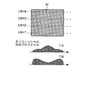
- the pit W in the present embodiment is one form of a drawing pattern, and a pattern having various shapes can be drawn without being limited to the pit.
- a line of pits W pit sequence WW is drawn using the lines LN1 to LN4 as one track.
- the profile of the electron beam has a spread (generally, a Gaussian shape), and the dose profile (dose distribution) varies depending on the forward and back scattering of the irradiation beam.
- the formatter 50 controls the interval between drawing lines adjacent to each other so that the dose profile of each line overlaps. Accordingly, the dose amount profile by drawing (beam irradiation) of the lines LN1 to LN4 is a combination of these.
- a pit W having an arbitrary shape can be formed by the pit pieces V (1) to V (4).
- the line drawing pattern is a row (pit piece sequence) of pit pieces V (1) to be drawn on the drawing line LN1, and the pit piece sequence of the line LN1 is, for example, k1 pit pieces V ( 1, k1).
- the formatter 50 includes a pit piece drawing end point (hereinafter referred to as “drawing start point”) VS (1) from the pit piece drawing start point (hereinafter simply referred to as drawing start point) of the pit piece V (1) on the line LN1. This is simply referred to as a drawing end point.) Drawing (beam irradiation) is performed up to VE (1). Thereby, drawing of the pit piece V (1) is performed.
- the drawing start position and the drawing end point, or set values of the pit piece drawing length described later are stored in the memory 53 or a storage unit provided in the EBR control signal generator (processor) 51.
- the memory 53 stores hard disk drawing pattern data (such as concentric circular patterns, track area patterns, servo area patterns, etc.) such as discrete track media and bit patterned media.
- the processor 51 generates a control signal for the EBR 10 using the drawing pattern data.
- the outer peripheral direction and inner peripheral direction offset signals F8 and F9 which are beam shift signals (second deflection signals) in the radial direction are not output, and the beam is shifted at high speed. The amount is zero. Therefore, the pit piece sequence VQ (1) of the line is drawn without shifting from the line LN1.
- the above steps S12 to S15 are executed for the line LN2, and the pit piece sequence VQ (2) is drawn on the line LN2.
- the beam is deflected (+ shifted) in the outer peripheral direction by the outer peripheral direction offset signal F8, and drawing is performed (FIG. 9).
- the pit piece V (2) is drawn from the drawing start point VS (2) to the pit piece drawing end point VE (2), and the pit piece V (2) is drawn. Is done.
- the drawing line LN3 is drawn from the drawing start point VS (3) to the pit piece drawing end point VE (3) in a state where the beam is deflected ( ⁇ shifted) to the inner circumference by the inner circumference direction offset signal F9. Drawing of the pit piece V (3) is performed (FIG. 9).
- the drawing line LN4 is not deflected by the outer and inner circumferential offset signals F8 and F9, but is drawn from the drawing start point VS (4) to the pit piece drawing end point VE (4). Drawing of the piece V (4) is performed (FIG. 9).
- step S15 When it is determined that the drawing line LN4 has been drawn, it is determined that drawing of the drawing pattern WW has ended (step S15), and this control is ended (FIG. 8).
- the substrate 15 on which drawing has been completed is processed into a hard disk mold (stamper) through a development process and an etching process.
- an arbitrarily shaped pit W can be formed by synthesizing the pit pieces V (1) to V (4). More specifically, the dose profile changes according to the overlapping of drawing of the pit pieces V (1) to V (4) or the beam intensity in drawing (beam irradiation). That is, the profile of the electron beam is broad (generally a Gaussian shape), and the dose profile changes depending on the forward and back scattering of the irradiation beam. Accordingly, the actual shape of the pit W (dose amount profile) is a combination of these. More specifically, as shown in FIG. 10, the dose profile in the radial direction can be adjusted by drawing the pit pieces V (1) to V (4). For example, the central portion in the radial direction can be strengthened as in the profile RA, or the edge portion in the radial direction can be strengthened as in the profile RB.
- the formatter 50 outputs a tangential deflection signal F16 (third deflection signal) and deflects the beam in a tangential direction or a circumferential direction (+ ⁇ , ⁇ direction) at a high speed when drawing the pit piece V (j).
- F16 third deflection signal
- the dose profile in the tangential direction or the circumferential direction can be adjusted.
- the central portion in the tangential direction can be strengthened as in the profile TA, or the edge portion in the tangential direction can be strengthened as in the profile TB.
- the offset amounts (offset signals F8 and F9) in the outer circumferential direction and the inner circumferential direction can be arbitrarily set, and the formatter 50 has a function of adjusting the offset amount according to the input overlapping degree.
- the formatter 50 generates and outputs the control signals F1 to F16 described above in order to form the drawing pattern of the arbitrary shape described above on the substrate 15.
- the formatter 50 controls the amount of drawing overwriting, the degree of overwriting of drawing lines (radial beam deflection amount) and the like based on drawing definition information data (hereinafter referred to as definition information) that defines a drawing pattern. And a control signal representing the control amount is generated.
- drawing mode CLV, CAV, etc.
- drawing position disk track, sector, etc.
- translation clock signal F4 The rotation clock signal F5 and the deflection signal F3 are generated and output.
- outer peripheral direction and inner peripheral direction offset signals F8, F9 outer peripheral direction and inner peripheral direction offset signals F8, F9, (3) tangential direction or circle Adjustment of the dose profile in the circumferential direction (tangential deflection signal F16) is performed.
- the formatter 50 receives drawing definition information such as a drawing mode, the number of overwriting, the degree of overlapping of drawing of each line, a drawing pit pattern (pit sequence) and individual pit shapes, for example, from the input / output unit.
- the control signal is automatically generated based on the definition information.
- the EBR control signal generator (processor) 51 of the formatter 50 displays drawing definition information such as a drawing pit pattern and pit shape for each drawing line in the outer peripheral direction and inner peripheral direction offset amount for each pit piece, and in the tangential direction.
- a conversion table for converting to the above-described deflection or the like is provided in advance, and the control signal described above is automatically generated based on the conversion table.
- the control by the formatter 50 described above can also be realized as a computer program. That is, the modulation signal F1, the deflection signal F3, the tangential deflection signal F16, the translation clock signal F4, the rotation clock signal F5, the drawing start signal F6, the drawing end signal F7, etc., which are the above control signals, are overwritten, the drawing pit pattern. Or a computer program including a designation or command generated based on drawing settings such as a pit shape or the like. The computer program can be executed by a processor to generate the control signal to control the electron beam recording apparatus.
- the case where the EBR 10 draws concentric lines has been described as an example.
- the above-described formatter 50 can be easily controlled even when pit pieces and pits are drawn on various beam trajectories. Can be modified and applied.
- the above-described control of the formatter 50 can be applied to a case where a line is drawn in a spiral shape (spiral shape).
- the formatter 50 generates the translation clock signal F4, the rotation clock signal F5, and the deflection signal F3 so that the track is spiral.
- the beam trajectory on the substrate 15 is spiral (broken line) by fixing the deflection (that is, the emission direction) of the electron beam EB.
- the beam deflection is performed by the deflection signal F3 so that the electron beam EB follows the substrate 15.
- the deflection signal F3 is constant during drawing in the drawing sequence shown in FIG.
- the beam deflection can be fixed. That is, drawing can be performed in a spiral shape.
- the beam direction is fixed by not applying or using the deflection signal (following deflection signal), so that drawing can be performed in a spiral shape.
- FIG. 12 schematically shows a spiral beam trajectory controlled by the formatter 50.
- the pit piece drawing of the pit piece V (j) on the line LSj is performed in the j-th rotation of the substrate 15.
- the pit piece V (j) is drawn.
- the pit piece drawing end point VE (j) is defined or set, and drawing (beam irradiation) is performed from the drawing start point VS (j) to the drawing end point VE (j). It may be.
- drawing start position and drawing end point, or set values of the pit piece drawing length are stored in the memory 53 or a storage unit provided in the EBR control signal generator (processor) 51.
- the beam is deflected (+ shifted) in the outer circumferential direction by the outer circumferential direction offset signal F8, or the beam is deflected ( ⁇ shifted) in the inner circumferential direction by the inner circumferential direction offset signal F9. It is also possible to draw in a state of being).
- the drawing in the drawing of the pit piece V (2) on the line LS2, the drawing is performed in a state where the beam is deflected ( ⁇ shifted) to the inner circumference by the inner circumference direction offset signal F9.
- the drawing of the pit piece V (3) on the line LS3 shows that the beam is deflected (+ shifted) in the outer peripheral direction by the outer peripheral direction offset signal F8 and drawing is performed.
- the profile of the dose amount in the radial direction can be adjusted by drawing the pit pieces V (2) to V (3).
- the edge portion in the radial direction of the pit W obtained by the synthesis of the pit pieces V (1) to V (4) becomes a dose amount profile enhanced compared to the central portion in the radial direction.
- the tangential direction can be obtained by outputting the tangential deflection signal F16 and deflecting the beam in the tangential direction or the circumferential direction (+ ⁇ , ⁇ direction) at a high speed when drawing the pit piece V (j).
- the dose profile in the circumferential direction can be adjusted.
- the dose adjustment by the tangential deflection signal F16 may be used alone, or may be used together with the dose adjustment by the outer peripheral direction offset signal F8 and / or the inner peripheral direction offset signal F9.
- a pit W having an arbitrary shape can be formed by synthesizing the pit pieces V (1) to V (4).
- the offset amounts (offset signals F8 and F9) and the tangential deflection signal F16 in the outer circumferential direction and the inner circumferential direction can be arbitrarily set, and the formatter 50 adjusts the offset amount according to the input overlapping degree. It has a function.
- the above pits can be drawn at any position on the substrate. Also, by setting the drawing start position and drawing end point or drawing length of each pit piece V (j), and the dose amount adjustment, it is possible to draw a pit having an arbitrary shape. Furthermore, one or a plurality of pits can be drawn on the substrate, and a plurality of pits can be drawn at positions adjacent to each other or discretely. For example, by drawing a plurality of pits at positions adjacent to each other, it is possible to draw one pit having an arbitrary shape formed by combining a plurality of pits.
- the present embodiment is applicable not only to electron beams but also to drawing using other means such as ion beams. Further, the present invention can be applied not only to a hard disk original plate but also to a fine structure such as an optical disk.
Landscapes
- Engineering & Computer Science (AREA)
- Chemical & Material Sciences (AREA)
- Nanotechnology (AREA)
- Manufacturing & Machinery (AREA)
- Physics & Mathematics (AREA)
- Crystallography & Structural Chemistry (AREA)
- General Physics & Mathematics (AREA)
- Condensed Matter Physics & Semiconductors (AREA)
- Analytical Chemistry (AREA)
- Mathematical Physics (AREA)
- Theoretical Computer Science (AREA)
- Manufacturing Optical Record Carriers (AREA)
- Electron Beam Exposure (AREA)
Abstract
L'enregistreur à faisceaux d'électrons selon la présente invention comporte une section de stockage destinée à stocker une valeur de consigne permettant de dessiner un élément de motif sur le substrat d'un faisceau d'électrons et un générateur de signaux modulés destiné à produire un signal modulé permettant au faisceau d'électrons de dessiner l'élément de motif sur le substrat sur la base de la valeur de consigne. La valeur de consigne est définie de telle sorte que le motif soit constitué de la combinaison des éléments de motif.
Priority Applications (1)
| Application Number | Priority Date | Filing Date | Title |
|---|---|---|---|
| PCT/JP2008/063907 WO2010013348A1 (fr) | 2008-08-01 | 2008-08-01 | Enregistreur à faisceaux d'électrons, son dispositif de commande et son procédé de commande |
Applications Claiming Priority (1)
| Application Number | Priority Date | Filing Date | Title |
|---|---|---|---|
| PCT/JP2008/063907 WO2010013348A1 (fr) | 2008-08-01 | 2008-08-01 | Enregistreur à faisceaux d'électrons, son dispositif de commande et son procédé de commande |
Publications (1)
| Publication Number | Publication Date |
|---|---|
| WO2010013348A1 true WO2010013348A1 (fr) | 2010-02-04 |
Family
ID=41610069
Family Applications (1)
| Application Number | Title | Priority Date | Filing Date |
|---|---|---|---|
| PCT/JP2008/063907 WO2010013348A1 (fr) | 2008-08-01 | 2008-08-01 | Enregistreur à faisceaux d'électrons, son dispositif de commande et son procédé de commande |
Country Status (1)
| Country | Link |
|---|---|
| WO (1) | WO2010013348A1 (fr) |
Citations (6)
| Publication number | Priority date | Publication date | Assignee | Title |
|---|---|---|---|---|
| JPH01235047A (ja) * | 1988-03-14 | 1989-09-20 | Sony Corp | デイスク状記録媒体加工装置 |
| JPH01315037A (ja) * | 1987-10-05 | 1989-12-20 | Hitachi Maxell Ltd | 光情報記録媒体用光学装置 |
| JPH11259916A (ja) * | 1998-03-10 | 1999-09-24 | Sony Corp | ディスク状記録媒体の製造方法及びその装置 |
| JP2005524104A (ja) * | 2002-04-24 | 2005-08-11 | オブデュキャット、アクチボラグ | リソグラフィ装置、方法およびコンピュータプログラムプロダクト |
| WO2008056400A1 (fr) * | 2006-11-06 | 2008-05-15 | Pioneer Corporation | Procédé de production d'un disque matrice |
| JP2008140419A (ja) * | 2006-11-29 | 2008-06-19 | Fujitsu Ltd | 電子ビームマスタリング装置及び回転ムラ補正方法 |
-
2008
- 2008-08-01 WO PCT/JP2008/063907 patent/WO2010013348A1/fr active Application Filing
Patent Citations (6)
| Publication number | Priority date | Publication date | Assignee | Title |
|---|---|---|---|---|
| JPH01315037A (ja) * | 1987-10-05 | 1989-12-20 | Hitachi Maxell Ltd | 光情報記録媒体用光学装置 |
| JPH01235047A (ja) * | 1988-03-14 | 1989-09-20 | Sony Corp | デイスク状記録媒体加工装置 |
| JPH11259916A (ja) * | 1998-03-10 | 1999-09-24 | Sony Corp | ディスク状記録媒体の製造方法及びその装置 |
| JP2005524104A (ja) * | 2002-04-24 | 2005-08-11 | オブデュキャット、アクチボラグ | リソグラフィ装置、方法およびコンピュータプログラムプロダクト |
| WO2008056400A1 (fr) * | 2006-11-06 | 2008-05-15 | Pioneer Corporation | Procédé de production d'un disque matrice |
| JP2008140419A (ja) * | 2006-11-29 | 2008-06-19 | Fujitsu Ltd | 電子ビームマスタリング装置及び回転ムラ補正方法 |
Similar Documents
| Publication | Publication Date | Title |
|---|---|---|
| JP4322919B2 (ja) | 電子ビーム描画装置 | |
| JP5191542B2 (ja) | 電子ビーム記録装置及びその制御装置並びに制御方法 | |
| JP2007041090A (ja) | 電子ビーム描画方法及び電子ビーム描画装置 | |
| EP1267340A2 (fr) | Appareil d'enregistrement d'informations et procédé d'enregistrement d'informations et support d'enregistrement d'informations | |
| JP2010135806A (ja) | ビーム記録方法及び装置 | |
| JP4746677B2 (ja) | ディスク原盤製造方法 | |
| US20040021976A1 (en) | Exposure dose control of rotating electron beam recorder | |
| JP4350471B2 (ja) | 電子ビーム描画方法および描画装置 | |
| JP5087679B2 (ja) | 電子ビーム装置 | |
| JP2002140840A (ja) | 光ディスク及びその原盤製造装置 | |
| WO2010013348A1 (fr) | Enregistreur à faisceaux d'électrons, son dispositif de commande et son procédé de commande | |
| JPWO2007116741A1 (ja) | 記録システム、記録装置及び記録制御信号生成装置 | |
| JP2002367241A (ja) | 情報記録装置及び情報記録方法並びに記録媒体 | |
| JP4481982B2 (ja) | 情報記録方法、および情報記録装置 | |
| JP5232864B2 (ja) | 電子ビーム描画装置の制御装置及び制御方法並びに描画方法 | |
| JP2002288890A (ja) | ビーム照射方法及び装置並びに記録媒体作成方法 | |
| WO2010023751A1 (fr) | Procédé servant à ajuster un dispositif de traçage de faisceau électronique et procédé servant à ajuster un dispositif de contrôle pour contrôler le dispositif de traçage de faisceau électronique | |
| JP2012141249A (ja) | 回転制御装置及び回転制御方法 | |
| WO2010014111A1 (fr) | Appareil d'enregistrement de faisceau d'électrons, appareil de commande et procédé de commande associés | |
| JP4647272B2 (ja) | 電子ビーム描画装置 | |
| US20100102254A1 (en) | Electron beam apparatus | |
| US20110188353A1 (en) | Electron beam lithography method, electron beam lithography apparatus, method for producing a mold, and method for producing a magnetic disk medium | |
| JP2010205326A (ja) | 電子線描画装置、ステージ位置偏差算出方法及びパターン描画方法 | |
| JP2002163845A (ja) | マスタリング装置及び記憶媒体基板の製造方法 | |
| JP2013025273A (ja) | 露光装置及びその制御方法 |
Legal Events
| Date | Code | Title | Description |
|---|---|---|---|
| 121 | Ep: the epo has been informed by wipo that ep was designated in this application |
Ref document number: 08792120 Country of ref document: EP Kind code of ref document: A1 |
|
| NENP | Non-entry into the national phase |
Ref country code: DE |
|
| NENP | Non-entry into the national phase |
Ref country code: JP |
|
| 122 | Ep: pct application non-entry in european phase |
Ref document number: 08792120 Country of ref document: EP Kind code of ref document: A1 |