WO2010007828A1 - 止め具 - Google Patents
止め具 Download PDFInfo
- Publication number
- WO2010007828A1 WO2010007828A1 PCT/JP2009/058623 JP2009058623W WO2010007828A1 WO 2010007828 A1 WO2010007828 A1 WO 2010007828A1 JP 2009058623 W JP2009058623 W JP 2009058623W WO 2010007828 A1 WO2010007828 A1 WO 2010007828A1
- Authority
- WO
- WIPO (PCT)
- Prior art keywords
- pin
- pair
- elastic engagement
- spring member
- leaf spring
- Prior art date
- Legal status (The legal status is an assumption and is not a legal conclusion. Google has not performed a legal analysis and makes no representation as to the accuracy of the status listed.)
- Ceased
Links
Images








Classifications
-
- F—MECHANICAL ENGINEERING; LIGHTING; HEATING; WEAPONS; BLASTING
- F16—ENGINEERING ELEMENTS AND UNITS; GENERAL MEASURES FOR PRODUCING AND MAINTAINING EFFECTIVE FUNCTIONING OF MACHINES OR INSTALLATIONS; THERMAL INSULATION IN GENERAL
- F16B—DEVICES FOR FASTENING OR SECURING CONSTRUCTIONAL ELEMENTS OR MACHINE PARTS TOGETHER, e.g. NAILS, BOLTS, CIRCLIPS, CLAMPS, CLIPS OR WEDGES; JOINTS OR JOINTING
- F16B19/00—Bolts without screw-thread; Pins, including deformable elements; Rivets
- F16B19/04—Rivets; Spigots or the like fastened by riveting
- F16B19/08—Hollow rivets; Multi-part rivets
- F16B19/10—Hollow rivets; Multi-part rivets fastened by expanding mechanically
- F16B19/1027—Multi-part rivets
- F16B19/1036—Blind rivets
- F16B19/1081—Blind rivets fastened by a drive-pin
-
- F—MECHANICAL ENGINEERING; LIGHTING; HEATING; WEAPONS; BLASTING
- F16—ENGINEERING ELEMENTS AND UNITS; GENERAL MEASURES FOR PRODUCING AND MAINTAINING EFFECTIVE FUNCTIONING OF MACHINES OR INSTALLATIONS; THERMAL INSULATION IN GENERAL
- F16B—DEVICES FOR FASTENING OR SECURING CONSTRUCTIONAL ELEMENTS OR MACHINE PARTS TOGETHER, e.g. NAILS, BOLTS, CIRCLIPS, CLAMPS, CLIPS OR WEDGES; JOINTS OR JOINTING
- F16B5/00—Joining sheets or plates, e.g. panels, to one another or to strips or bars parallel to them
- F16B5/06—Joining sheets or plates, e.g. panels, to one another or to strips or bars parallel to them by means of clamps or clips
- F16B5/0607—Joining sheets or plates, e.g. panels, to one another or to strips or bars parallel to them by means of clamps or clips joining sheets or plates to each other
- F16B5/0621—Joining sheets or plates, e.g. panels, to one another or to strips or bars parallel to them by means of clamps or clips joining sheets or plates to each other in parallel relationship
- F16B5/0642—Joining sheets or plates, e.g. panels, to one another or to strips or bars parallel to them by means of clamps or clips joining sheets or plates to each other in parallel relationship the plates being arranged one on top of the other and in full close contact with each other
-
- F—MECHANICAL ENGINEERING; LIGHTING; HEATING; WEAPONS; BLASTING
- F16—ENGINEERING ELEMENTS AND UNITS; GENERAL MEASURES FOR PRODUCING AND MAINTAINING EFFECTIVE FUNCTIONING OF MACHINES OR INSTALLATIONS; THERMAL INSULATION IN GENERAL
- F16B—DEVICES FOR FASTENING OR SECURING CONSTRUCTIONAL ELEMENTS OR MACHINE PARTS TOGETHER, e.g. NAILS, BOLTS, CIRCLIPS, CLAMPS, CLIPS OR WEDGES; JOINTS OR JOINTING
- F16B21/00—Means for preventing relative axial movement of a pin, spigot, shaft or the like and a member surrounding it; Stud-and-socket releasable fastenings
- F16B21/10—Means for preventing relative axial movement of a pin, spigot, shaft or the like and a member surrounding it; Stud-and-socket releasable fastenings by separate parts
-
- Y—GENERAL TAGGING OF NEW TECHNOLOGICAL DEVELOPMENTS; GENERAL TAGGING OF CROSS-SECTIONAL TECHNOLOGIES SPANNING OVER SEVERAL SECTIONS OF THE IPC; TECHNICAL SUBJECTS COVERED BY FORMER USPC CROSS-REFERENCE ART COLLECTIONS [XRACs] AND DIGESTS
- Y10—TECHNICAL SUBJECTS COVERED BY FORMER USPC
- Y10T—TECHNICAL SUBJECTS COVERED BY FORMER US CLASSIFICATION
- Y10T24/00—Buckles, buttons, clasps, etc.
- Y10T24/30—Trim molding fastener
- Y10T24/304—Resilient metal type
- Y10T24/307—Sheet metal formed
Definitions
- the present invention relates to a stopper that is inserted and fixed in a mounting hole formed in a body panel of an automobile, for example.
- a stopper when attaching a mounting member such as a trim board to a mounting member such as a body panel of an automobile, a stopper is used.
- Patent Document 1 discloses a synthetic resin pin, a metal leaf spring member for receiving the pin and fixing the mounting member and the mounted member, and a synthetic resin.
- the leaf spring member is composed of a receiving portion having a pin through hole and a pair of leg portions, and the pair of leg portions has a shape in which both ends thereof are folded inward, When a pin is pushed between the leg parts, a pair of leg parts are configured to expand, and the grommet has a main body part that contains a leaf spring member, and the leg part is provided at the upper end of the main body part.
- a clip is disclosed in which an extension portion that can follow the expansion of the clip is formed.
- a pin is inserted into the through hole of the spring member, and in a state where the leaf spring member is fitted to the grommet body, the clip is inserted into an attachment hole formed in the attachment member and the attached member, and the pin is inserted.
- the pair of leg portions of the spring member are expanded from the inside, and the expansion portion of the grommet main body portion is accordingly expanded to engage with the peripheral edge of the mounting hole, and both members are connected via the clip. Is pinched and fixed.
- the clip of Patent Document 1 is configured to push and spread the pair of leg portions of the spring member by pushing the pin, so that the pair of leg portions of the spring member is expanded beyond the outer diameter of the pin.
- the width in which the pair of legs expands is constant, and as a result, the expansion width of the expanded part of the grommet expanded by the pair of legs is also constant.
- the thickness of the member to be attached becomes thin over time with the clip fixed, a gap may be formed between the periphery of the attachment hole and the clip may become loose. It was.
- the expansion width of the expanded portion of the grommet is determined by the outer diameter of the pin, for example, due to a dimensional error, the inner diameter of the mounting hole is larger than the standard dimension, or the plate of the mounted member If the thickness is small, there is a risk that the clip may rattle with respect to the mounting hole.
- an object of the present invention is to provide a stopper that can be firmly engaged with the mounting hole without being affected by the variation in the thickness of the member provided with the mounting hole or the size of the inner diameter of the mounting hole. It is to provide.
- the present invention is a stopper that includes a pin and a metal leaf spring member that receives the pin, and is fixed to the attachment hole, wherein the leaf spring member includes the attachment hole.
- a base part that engages the front side and has an insertion hole for the pin, and extends from the base part, and can engage with each other when pressed against the elastic restoring force and closed from a free state.
- An engagement shoulder that can pass through the attachment hole is formed, and the pin has a head and a shaft extending from the head, and the shaft is closed with the pair of elastic members.
- the pair of elastic engagement pieces When inserted between the engagement pieces, the same pair of elastic engagement pieces are disengaged to open and open.
- the pair of elastic engagement pieces When positioned between the pair of elastic engagement members, the pair of elastic engagement pieces to provide a stop, characterized in
- each tip of the pair of elastic engagement pieces is bent inward to form a bent portion, and each bent portion is formed at a position shifted from each other in the width direction.
- the engaging protrusion is formed on one or both of the inner sides adjacent to each other in the width direction, and when the elastic engaging piece is closed, one of the engaging protrusions is the other inner side or the other engaging protrusion.
- the elastic engagement piece is configured to be able to be held in a closed state, and the elastic engagement piece is closed on the base side from the engagement protrusion of each bent portion.
- an abutting piece is formed to which the tip of the pin abuts and a pressing force is applied, and the pressing force along the inserting direction of the pin is applied to the corresponding piece.
- the abutting portions for changing the pressing force to the outward in the width direction of the abutting pieces are respectively formed, and the shaft portion of the pin is closed by the elastic engagement When inserted between the, it is preferable that the distal end is configured to abut against the contact piece.
- each contact piece of the bent portion is bent so that the tip portion approaches the back side of the corresponding elastic engagement piece, and is adjacent to the width direction of each contact piece.
- the inner sides are inclined toward the outer side in the width direction so as to be separated from each other toward the tip, the inclined inner side forms the contact portion, and the tip portion of the shaft portion of the pin is a pin It is preferable to form a taper shape that contacts the inclined inner side of the contact piece during pressing.
- the bent portion of the leaf spring member is It is preferable that a reduced diameter portion to be fitted is formed.
- a pair of narrow portions are formed at a position positioned between and opposed to the pair of elastic engagement pieces.
- the base portion is preferably configured to bend at the pair of narrow portions when the pair of elastic engagement pieces bend.
- each narrow portion formed in the base portion of the leaf spring member is disposed on both sides orthogonal to the bending direction of the pair of elastic engagement pieces of the base portion, and the base portion is When viewed in the axial direction, each elastic engagement piece is preferably formed at a position biased to the width direction side where the bent portion is not formed.
- the shaft portion of the pin when arranged between the pair of elastic engagement pieces, abuts on the base side from the engagement shoulder portion of the same pair of elastic engagement pieces, It is preferable that an enlarged diameter portion that does not come into contact with the engagement shoulder portion and the tip end side is formed.
- a grommet is further provided.
- the grommet extends from the rear side of the base portion and engages with the front peripheral edge of the mounting hole.
- the base portion is provided with an insertion port through which the pair of elastic engagement pieces of the leaf spring member and the shaft portion of the pin are inserted, and the base portion and the shaft portion of the pin,
- a holding means for temporarily holding the pin inserted into the leaf spring member through the insertion hole at a position where no pressing force is applied to the contact piece is provided, and a pair of elastic engagements of the leaf spring member
- the piece is provided with a retaining claw that engages with the back side peripheral edge of the insertion opening of the base portion on the base side of the engagement shoulder, and the retaining claw is provided on the back side peripheral edge of the insertion opening of the base portion.
- the shaft portion of the pin has a temporary holding portion that temporarily holds the pin on the grommet at a position where no pressing force is applied to the contact piece of the leaf spring member, and the head portion of the pin spring is the leaf spring. It is preferable that a fixing portion is provided that fixes the pin to the grommet when the pin is pushed in until it is engaged with the periphery of the insertion hole of the member.
- the leg portions of the grommets are each a pair of leaf spring members held by the grommets arranged in a direction perpendicular to the bending direction of the pair of elastic engagement pieces. It is preferable to consist of things.
- the legs of the grommets are composed of a pair of ones arranged in the bending direction of the pair of elastic engagement pieces and outside the same pair of elastic engagement pieces. preferable.
- the pair of legs of the grommet have a shape in which the tips are connected to each other and the diameter is reduced toward the tip.
- the grommet has a guide leg portion having an engaging groove extending along the axial direction at a position orthogonal to the pair of leg portions, and the shaft portion of the pin has When the pin is pushed in until the head of the pin is engaged with the periphery of the insertion hole of the leaf spring member, a pair of protrusions are formed that engage with the inner periphery of both ends of the engagement groove. It is preferable.
- the pair of elastic engagement pieces opened in a free state are closed by pressing inward against the elastic restoring force, and engaged with each other in that state, whereby the engagement shoulder portion is attached to the mounting hole.
- the plate spring member reduces the insertion resistance and prevents the engagement shoulder portion from being caught in the attachment hole or being pushed into the inner periphery of the attachment hole while being strongly pressed. Can be smoothly inserted into the mounting hole.
- the elastic engagement piece of the leaf spring member is engaged with the back side peripheral edge of the attachment hole with elastic restoring force, the plate thickness of the member in which the attachment hole is formed is changed, or the inner diameter of the attachment hole is changed. Even if it is larger or smaller than the standard dimension, the pair of elastic engagement pieces can be elastically expanded and contracted, and the engagement shoulder can be kept engaged with the rear edge of the mounting hole. It can be attached to the mounting hole without play.
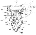
- FIG. 1 It is a perspective view which shows one Embodiment of the fastener of this invention.
- A is a perspective view of the state which the elastic engagement piece of the leaf
- (B) is a perspective view of the state which the elastic engagement piece of the leaf
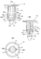
- A) is a front view of a leaf
- B) is a side view,
- C) is a bottom view.
- (A) is a front view of the pin which comprises a stopper,
- B) is a side view,
- C) is a bottom view.
- A) is a top view of the grommet which comprises a stopper,
- B) is sectional drawing in the AA arrow line of (A).
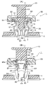
- (A) is explanatory drawing which shows a cross section except a leaf
- (B) is explanatory drawing when it sees from a different direction from (A). The process which cancels
- (A) is explanatory drawing which shows a 1st process
- (B) is explanatory drawing which shows a 2nd process
- ( (C) is explanatory drawing which shows a 3rd process. It is a perspective view which shows other embodiment of the fastener of this invention.
- (A) is a perspective view of the state which the elastic engagement piece of the leaf
- (B) is a perspective view of the state which the elastic engagement piece of the leaf
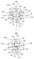
- (A) is a bottom view of the state where the elastic engagement piece of the leaf spring member is opened
- (B) is a bottom view of the state where the elastic engagement piece of the leaf spring member is closed.
- (A) is a perspective view of the pin which comprises a stopper
- (B) is a perspective view of the grommet which comprises a stopper. It is a perspective view of the state which assembled
- the fastener 1 is inserted and fixed in an attachment hole 3 formed in a member 2 to be attached such as a vehicle body panel, and the trim board or the like is inserted through the fastener 1.
- the mounting member 4 is used for mounting to the mounted member 2.
- the stopper 1 in this embodiment includes a pin 10, a metal leaf spring member 30 that receives the pin 10, and a grommet 50 that holds both.
- the leaf spring member 30 is formed from a single metal plate material, and extends from the base portion 31 and closes when pressed against an elastic restoring force in a free state and pressed against each other. It has a pair of elastic engagement pieces 35, 35 that can be engaged.
- the base 31 has a circular shape as a whole, and a circular insertion hole 31a for inserting the pin 10 is formed at the center thereof. Moreover, a pair of notches 31b and 31b are formed in the inner periphery of the insertion hole 31a at positions orthogonal to the pair of elastic engagement pieces 35 and 35. Each notch 31b forms a pair of narrow portions 31c and 31c at opposing positions on the outer periphery of the insertion hole 31a of the base 31. When the pair of elastic engagement pieces 35 and 35 are bent, the base 31 is It is comprised so that it may be bent by a pair of narrow part 31c, 31c (refer FIG. 2 (B)).
- a band-shaped piece having a predetermined width protrudes from both side portions of the base portion 31 orthogonal to the notches 31b and 31b, and is folded back inward so as to be viewed from the side as shown in FIG.
- Bent portions 33, 33 that are bent in a substantially U shape are formed.
- the base end portions of the elastic engagement pieces 35 are connected to the bent portions 33 and 33, respectively.
- the U-shaped bent portion 33 plays a role of improving the elastic restoring force of the elastic engagement pieces 35 and 35 connected thereto.
- the base end portions of the pair of elastic engagement pieces 35, 35 extend from the U-shaped bent portion 33 with respect to the base portion 31 and extend at a predetermined angle.
- the pawls 36 and 36 are cut and raised outward.
- the retaining claws 36, 36 are engaged with the rear peripheral edge of an insertion port 53 of the grommet 50 described later to prevent the leaf spring member 30 from coming off (see FIGS. 7 to 9).
- the engagement shoulder portion 37 has an arc shape corresponding to the circular mounting hole 3 and having a convex curved surface outward in the radial direction (see FIGS. 2, 3B, and 3C). .
- each elastic engagement piece 35 is bent inward to form bent portions 40, 40, and the bent portions 40, 40 are further as shown in FIGS. 3 (B), (C). Further, it is formed at a position shifted from each other in the width direction, and is configured so that the two bent portions 40 and 40 do not interfere when the pair of elastic engagement pieces 35 and 35 are closed close to each other.
- Engagement protrusions 43 and 43 project from the inner sides adjacent in the width direction of the bent portions 40 and 40 toward the other adjacent bent portion 40, respectively.
- Each engagement protrusion 43 is formed at a position that overlaps when the elastic engagement pieces 35 are closed.
- the elastic engagement pieces 35 and 35 are closed, as shown in FIG. 2B, the engagement protrusions 43 and 43 are engaged with each other, and the elastic engagement pieces 35 and 35 are closed. It is designed to hold the state.
- the engaging protrusion 43 may be formed only on one of the bent portions 40. In this case, when the elastic engagement pieces 35, 35 are closed, the engagement protrusion 43 of the one bent portion 40 is moved to the back side of the inner side of the other bent portion 40 (the opposite surface of the one bent portion 40. And the elastic engagement pieces 35, 35 are closed.
- the contact piece 45 is bent and formed in a “U” shape when viewed from the side so that the distal end portion of the bent portion 40 faces the back side of the elastic engagement piece 35. Yes.
- each contact piece 45 is formed with a contact portion for changing the direction of the pushing force along the insertion direction of the pin 10 to the outward direction of the contact piece 45 in the width direction.
- the inner sides adjacent to each other in the width direction of the contact pieces 45 are inclined inward sides that gradually go outward in the width direction and gradually incline toward the base 31 side of the leaf spring member 30. This inclined inner side forms a contact portion 45a (see FIGS. 2 and 10).
- These abutting portions 45a and 45a abut against the outer peripheral surface of the conical tip portion 15 of the pin 10 when the pin 10 is inserted with the elastic engagement pieces 35 and 35 closed. (See FIG. 6).
- the pin 10 received by the leaf spring member 30 having the above structure will be described with reference to FIG. 4 and FIGS.
- the pin 10 is the same.
- the elastic engagement pieces 35 and 35 are disengaged and opened, and the shaft 13 is disposed between the elastic engagement pieces 35 and 35 in the opened state and restricts closing to the inside.
- the tip portion of the shaft portion 13 has a tapered shape that abuts against the inclined inner side of the abutting piece 45 when the pin is pushed.
- the shaft portion 13 in this embodiment has a substantially cylindrical shape, and the tip portion 15 has a conical shape. Then, as shown in FIG. 6, the distal end portion 15 of the shaft portion 13 is brought into contact with each contact portion 45 a having the inclined surface shape of the contact piece 45 of the elastic engagement pieces 35, 35 in the closed state. It has become.
- Guide ribs 17 and 17 having a predetermined height extend along the axial direction at two locations facing the circumferential direction on the base side of the shaft portion 13, and the guide ribs 17 and 17 push the pin 10 into the grommet 50. As it goes, it fits into a slit 56 (described later) of the grommet 50 and becomes a push guide for the pin 10.
- the leaf spring member is A diameter-reduced portion 19 into which 30 bent portions 40 are fitted is formed, and an inner surface on the distal end side thereof forms a reverse tapered surface 19a gradually expanding toward the distal end portion 15, and an inner surface on the proximal end side.
- plate-like pieces 21 and 21 are projected from the inner periphery of the reduced diameter portion 19 at positions aligned with the guide ribs 17 and 17.
- a bending piece 25 is provided at the tip of the guide rib 17 and the tip of the plate-like piece 21 so as to be connected in a bridge shape via a punch hole 23 and bendable.
- An engagement protrusion 25a is provided on the proximal end side of the bending piece 25, and an engagement claw portion 25b is provided on the distal end side.
- the engaging protrusion 25a and the engaging claw portion 25b are engaged with the upper and lower edges of the base portion 51 of the grommet 50 as shown in FIG. It arrange
- the grommet 50 includes a disk-shaped base portion 51 and a pair of leg portions 55 and 55 extending from the back surface side of the base portion 51.
- An annular wall 52 protrudes from the outer periphery of the upper end of the base portion 51, and a circular shape in which the shaft portion 13 of the pin 10 and the elastic engagement piece 35 of the leaf spring member 30 are inserted into the center of the base portion 51.
- An insertion port 53 is formed.
- a fitting recess 54 is formed on the upper surface of the base portion 51 with a predetermined width through the center of the insertion port 53, and the bent portions 33, 33 of the leaf spring member 30 are fitted thereto to prevent rotation. It has been made.
- the pair of leg portions 55, 55 are arranged in a direction perpendicular to the bending direction of the pair of elastic engagement pieces 35, 35 of the leaf spring member 30 held by the grommet 50. .
- a slit 56 is formed at the center of each leg 55 in the width direction along the extending direction.
- Each leg portion 55 is composed of guide pieces 57 and 57 that are divided into two via slits 56.
- a protrusion 58 that protrudes inward is provided inside each guide piece 57, and the outer periphery of the tip of the guide piece 57 has a shape that gradually decreases in diameter toward the tip.
- the pair of elastic engagement pieces 35 and 35 of the leaf spring member 30 constituting the stopper 1 are opened apart from each other in a free state where no external force is applied (FIG. 2A). )reference). From this state, the pair of elastic engagement pieces 35 and 35 are pressed inward against the elastic restoring force, and both elastic engagement pieces 35 and 35 are closed.
- the bent portions 40 and 40 are separated from each other in the width direction between the elastic engaging pieces 35 and 35.
- the engagement protrusions 43 By moving the engagement protrusions 43 so as to be close to each other, the engagement protrusions 43 are engaged with the back surface side of the other engagement protrusions 43 (opposite the opposite surface of the engagement protrusions 43).
- the elastic engagement pieces 35 and 35 can be held in a closed state (see FIG. 2B).
- the engaging protrusion 43 is formed on one of the bent portions 40, the engaging protrusion 43 of one bent portion 40 is connected to the back side of the inner side of the other bent portion 40.
- the pair of elastic engagement pieces 35, 35 can be held closed.
- a pair of narrow widths are formed between the pair of elastic engagement pieces 35, 35 on the outer periphery of the insertion hole 31 a formed in the base portion 31 of the leaf spring member 30 and at positions facing each other. Portions 31c and 31c are formed.
- the base portion 31 is bent at the pair of narrow portions 31c and 31c as shown in FIG.
- the pieces 35 and 35 can be easily bent to improve workability when the elastic engagement pieces 35 and 35 are engaged with each other, and the elastic engagement pieces 35 and 35 are engaged with each other by pressing the pin 10. The release operation when releasing is performed smoothly.
- the bent portions 33 and 33 of the leaf spring member 30 are aligned with the fitting recesses 54 and 54 of the grommet 50, and the leaf spring is inserted into the insertion port 53 of the grommet 50.
- the elastic engagement pieces 35 and 35 of the member 30 are pushed in.
- the closed elastic engagement pieces 35, 35 are inserted between the legs 55, 55 of the grommet 50, and when the leaf spring member 30 is completely pushed in, the U-shaped bent portions 33, 33 are fitted.
- the retaining claws 36, 36 provided on the elastic engagement piece 35 are engaged with the rear peripheral edge of the insertion opening 53.
- the leaf spring member 30 can be held with respect to the grommet 50.
- the pair of legs 55, 55 of the grommet 50 are disposed on both sides of the pair of elastic engagement pieces 35, 35, respectively. Since the movement of the pin 10 in the direction perpendicular to the bending direction of the elastic engagement piece 35 is restricted, the tip 15 of the pin 10 is reliably pressed against the contact pieces 45 and 45 of the leaf spring member 30. be able to.
- the pin 10 is temporarily held with respect to the grommet 50. That is, the guide ribs 17 and 17 of the pin 10 are aligned with the slits 56 and 56 of the grommet 50 and the notches 31 b and 31 b of the leaf spring member 30, and pass through the insertion hole 31 a of the leaf spring member 30 and the insertion port 53 of the grommet 50. Push the pin halfway. As a result, the engagement protrusion 25a and the engagement claw portion 25b engage with the upper and lower edges of the base portion 51, and the pin 10 is retained by the grommet 50 (see FIG. 7B). At this time, as shown in FIGS. 6 and 7A, the tip 15 of the pin 10 holds the elastic engagement pieces 35 and 35 in a closed state without applying a pressing force to the contact piece 45. It is supposed to let you.
- the leaf spring member 30 can be prevented from coming off and held in the grommet 50 by pushing the closed elastic engagement pieces 35 into the insertion opening 53 of the grommet 50.
- the holding means engagement protrusion 25a of the pin 10
- the pin 10 can be temporarily held by the grommet 50 by the engaging claw portion 25b and the base portion 51 of the grommet 50).
- the grommet 50 for holding both is provided, so that the leaf spring member 30 and the pin 10 can be assembled in advance via the grommet 50 and attached.
- the workability at the time of fixing to the hole 3 can be improved.
- the mounting hole 5 of the mounting member 4 is aligned and overlapped with the mounting hole 3 of the mounted member 2 (see FIG. 7), and the distal end side of the stopper 1 assembled by the above process is inserted from the mounting hole 5.
- the base portion 51 of the grommet 50 is brought into contact with the front peripheral edge of the mounting hole 5, and the distal end side of the elastic engagement piece 35 of the leaf spring member 30 and the leg portion 55 of the grommet 50 are protruded from the mounting hole 3.
- each leg portion 55 is composed of guide pieces 57 and 57 divided into two into slits 56, and thus has high flexibility, so that insertion resistance can be reduced while maintaining guide performance.
- the pair of elastic engagement pieces 35, 35 opened in a free state are closed by pressing inward against the elastic restoring force and engaged with each other in this state, thereby engaging shoulders.
- the attachment hole 3 passes through the attachment hole 3, it is suppressed that the engagement shoulder is caught in the attachment hole 3 or the elastic engagement piece 35 is pushed into the inner periphery of the attachment hole while being strongly pressed. It can be inserted smoothly with less.
- each contact portion 45a of the contact piece 45 forms an inclined surface
- the tip portion 15 of the shaft portion 13 of the pin 10 has a conical shape. Therefore, when the pin 10 is pushed, 10 conical tip portions 15 abut on an inclined contact portion 45a forming the inner side of the contact piece 45, and the contact portion 45a of the contact piece 45 and the conical surface of the tip portion 15 of the pin 10 The pin 10 is pushed in while sliding.
- the pushing force F1 (see FIG. 6) of the pin 10 is converted into a force pushing the contact piece 45 outward in the width direction by the contact portion 45a provided on the contact piece 45 of the leaf spring member 30. .
- the contact pieces 45 and 45 bent at a predetermined angle of the leaf spring member 30 have a conical shape of the pin 10.
- the outer periphery of the tip portion 15 is slanted.
- the engagement shoulder portions 37, 37 of the elastic engagement piece 35 engage with the rear peripheral edge of the attachment hole 3 of the attached member 2 and the base of the grommet 50.
- the part 51 engages with the front side peripheral edge of the attachment hole 5 of the attachment member 4, and the attachment member 2 and the attachment member 4 are sandwiched between them, so that the attachment member 4 can be attached to the attachment member 2.
- the shaft portion 13 of the pin 10 is arranged between the pair of elastic engagement pieces 35, 35, the inward bending of the elastic engagement pieces 35, 35 is restricted, and the leaf spring from the mounting hole 3 is restricted.
- the member 30 is prevented from coming off.
- the tip portion 15 is brought into contact with the contact piece 45 of the bent portion 40 as described above.
- a pressing force is applied by abutting, and the abutting portion 45a changes the pressing force into a force pushing the abutting piece 45 outward in the width direction, so that the pair of elastic engagement pieces 35, 35 are positioned in the width direction. Since the engagement can be released by shifting, the engagement of the pair of elastic engagement pieces 35, 35 in a closed state can be smoothly released by a simple operation of simply pushing the pin 10, The attachment workability of the stopper 1 can be improved.
- the bent portion of the leaf spring member 30 is provided.
- a reduced-diameter portion 19 that fits 40 is formed. That is, in the state where the stopper 1 is fixed to the mounting hole, as shown in FIG. 8A, the bent corner portion of the bent portion 40 is engaged with the reverse tapered surface 19a and the bent portion is bent. Since the contact piece 45 of the portion 40 is engaged with the tapered surface 19b and the bent portion 40 is fitted to the reduced diameter portion 19, it is ensured that the pin 10 is detached from the leaf spring member 30. Can be prevented.
- plate spring member 30 which comprises this stopper 1 open in a free state, and engage with the back side periphery of an attachment hole with an elastic restoring force. Therefore, even if the plate thickness of the mounted member 2 in which the mounting hole 3 is formed changes or the inner diameter of the mounting hole 3 is larger or smaller than the standard dimension, a pair of elastic engagements corresponding to the flexibility.
- the pieces 35 and 35 are elastically expanded or contracted in diameter, and the engagement shoulders 37 and 37 can be reliably maintained in press contact with the back side peripheral edge of the attachment hole 3.
- the stopper 1 can be firmly fixed to the hole 3 without rattling.
- each contact portion 45a of the contact piece 45 has an inclined inner side
- the tip portion 15 of the shaft portion 13 of the pin 10 has a tapered shape (here, a conical shape). Therefore, when the pin 10 is pushed in from the insertion hole 31a of the leaf spring member 30 with the pair of elastic engagement pieces 35, 35 inserted in the mounting holes 3, 5, the conical tip 15 is inclined. Since the pin 10 is pushed in while sliding along the contact portion 45a, the pushing force F1 (see FIG. 6) of the pin 10 is used as the force F2 pushing the contact piece 45 outward in the width direction. (See FIG. 10A) can be efficiently converted, and the disengagement work of the pair of elastic engagement pieces 35 can be performed quickly.
- stopper 1 of this embodiment is comprised from the pin 10, the leaf
- the U-shaped bent portion 33 of the leaf spring member 30 directly contacts the periphery of the mounting hole of the mounting member.
- the stopper 1a in this embodiment includes a pin 10a, a leaf spring member 30a, and a grommet 50a as in the above embodiment.
- each member 10a, 30a, 50a is demonstrated centering on a different part from the member 10, 30, 50 of the said embodiment.
- each narrow portion 31c, 31c is in a direction orthogonal to the bending direction (see arrow B) of the pair of elastic engagement pieces 35, 35 of the base 31 (see line segment C). ), And when the base 31 is viewed in the axial direction, the bent portions 40, 40 of the respective elastic engagement pieces 35 are located at positions deviated in the width direction, respectively. Is formed. That is, in the drawing, the upper narrow portion 31c is formed at a position biased to the width direction side where the bent portion 40 of the left elastic engagement piece 35 is not formed, and the lower narrow portion 31c is formed on the right side.
- the bent portion 40 of the elastic engagement piece 35 is formed so as to be biased toward the width direction side where it is not formed.
- the insertion hole 31a extends through the center in the width direction of the U-shaped bent portion 33 to reach the front side of the engagement shoulder portion 37, and the base side of the elastic engagement piece 35 is cut away.
- a retaining claw 36 is formed obliquely outwardly at the center in the width direction on the base side of the elastic engagement piece 35 through the notched portion.
- a triangular plate-shaped protruding piece is directed toward the other adjacent bent portion 40. It protrudes (see FIG. 12B, FIG. 13A, and FIG. 15).
- the base side of the leaf spring member 30a of the projecting piece forms an abutting piece 45 to which a distal end portion 15a (described later) of the pin 10a comes into contact and is given a pushing force, and the distal end of the leaf spring member 30a of the projecting piece
- the part side constitutes an engagement protrusion 43 that holds the elastic engagement pieces 35, 35 in a closed state.
- an enlarged diameter portion 14 having a plate shape wider than the tip portion is formed on the base side of the shaft portion 13.
- the enlarged diameter portion 14 abuts on the base side with respect to the engagement shoulder portion 37, but the engagement shoulder portion 37 and more than that. The length does not come into contact with the distal end side, and extends toward the distal end of the shaft portion (see FIG. 17).
- each bending wall portion 18 is provided with fixed protrusions 18b, 18b having a tapered tip at the shaft end and a stepped portion at the base end.
- the fixed protrusion 18b is engaged with the inner periphery of the proximal end portion of the engagement groove 59a of the grommet 50a described later. (See FIG. 18). That is, the fixed protrusion 18b forms a fixed part for fixing the pin to the grommet and also forms a protrusion that engages with the inner periphery of the engagement groove 59a.
- the tip portion 15a of the shaft portion 13 is formed in a triangular plate shape, and both sides thereof have a tapered shape that gradually increases in width toward the head portion 11 side.
- Bridge-like bending pieces 25 and 25 are respectively connected to both sides of the proximal end of the distal end portion 15a and the respective distal ends of the enlarged diameter portions 14 and 14, and the engagement protruding portions 25a and the engaging claws are connected to the respective bending pieces 25.
- Each portion 25b is formed.
- a rectangular insertion port 53a (see FIGS. 15 and 16) is formed at the center of the base portion 51. From the opposite side edges on the back side of the insertion port 53a, A pair of leg portions 55a, 55a arranged in the bending direction of the pair of elastic engagement pieces 35, 35 and outside the elastic engagement pieces 35, 35 are extended (FIGS. 11, 16, 17). reference). Further, each leg 55a, 55a has a shape (here, substantially V-shaped) in which the tips are connected to each other and the diameter is reduced toward the tip. A long groove 55b is formed at the center in the width direction of each leg 55a along the extending direction of the leg 55a.
- the long groove 55b makes the leg portion 55a easy to bend when the leg portion 55a is pressed from the inside by the elastic engagement piece 35, and prevents the retaining claw 36 from holding when the leaf spring member 30a is held by the grommet 50a. Will be the part that enters.
- a pair of guide leg portions 59, 59 are extended from both side edges of the insertion opening 53a of the base portion 51 perpendicular to the leg portions 55a, 55a.
- Each guide leg 59, 59 is arranged at a position orthogonal to the bending direction of the elastic engagement piece 35 and between the pair of elastic engagement pieces 35, 35, respectively.
- Each guide leg 59 has an engaging groove 59a extending in the axial direction (the direction in which the guide leg 59 extends).
- the narrow portions 31c, 31c provided on the base 31 are disposed on both sides orthogonal to the bending direction of the elastic engagement piece 35 of the base 31, and the base 31 is pivoted.
- each elastic engagement piece 35 is formed at a position biased to the width direction side where the bent portion 40 is not formed (see FIG. 13A). Therefore, when the pair of elastic engagement pieces 35, 35 are bent inward, they are bent around the line L in FIG. 13A, and one engagement protrusion 43 and the other engagement protrusion 43 are bent. As shown by an arrow D, move toward each other in the width direction.
- the pair of elastic engagement pieces 35 and 35 are aligned with the pair of leg portions 55a and 55a of the grommet 50a and pushed into the insertion port 53a, whereby the pair of retaining claws 36 and 36 are attached to the leg portions 55a.
- the retaining claws 36 and 36 are engaged with the periphery of the back side of the insertion port 53a (see FIG. 16), so that the leaf spring member 30a can be held by the grommet 50a.
- the plate-like enlarged diameter portion 14 of the pin 10a is aligned with both sides of the slit-like insertion hole 31a of the leaf spring member 30a, and the pair of notches 31b and 32b of the leaf spring member 30a are aligned with the pair of notches 31b and 32b.
- the pair of bending wall portions 18 and 18 and pushing the pin 10a to a predetermined depth, as shown in FIG. 15, the upper and lower edges of the base portion 51 are engaged with the engaging protrusions 25a and the engaging claws 25b. Are engaged with each other, and the pin 10a is retained by the grommet 50a. In this state, both tapered sides of the tip portion 15a of the pin 10a come into contact with the contact portions 45a and 45a of the contact pieces 45, respectively.
- the temporary holding part (engagement protrusion 25a and engagement claw part 25b) and the fixing part (fixation protrusion 18b) are provided on the shaft part 13 of the pin 10a. Since the grommet 50a can be temporarily held and fixed permanently, it is not necessary to provide the leaf spring member 30a with a structure for preventing the pin 10a from coming off, and the rigidity, springiness, elastic restoring force, etc. of the leaf spring member 30a can be reduced. It can be secured firmly.
- the stopper 1 assembled in the above process is inserted into the mounting holes 5 and 2 of the mounting member 4 and the mounted member 2.
- the pin 10a is pushed in with respect to the grommet 50a. Then, the engagement of the contact pieces 45, 45 is released by the triangular plate-shaped tip portion 15a, and the pair of elastic engagement pieces 35, 35 are opened, and the legs of the grommet 50a are opened by the engagement shoulder portions 37, 37.
- the parts 55a and 55a are spread from the inside. As a result, the engagement shoulders 37, 37 of each elastic engagement piece 35 are indirectly engaged with the peripheral edge on the back side of the mounting hole 3 via the leg portions 55a, 55a, and are covered via the stopper 1a.
- the attachment member 4 can be attached to the attachment member 2 (see FIG. 17).
- the tip portion 15a of the pin 10a has a triangular plate shape, and both sides thereof come into contact with the contact portions 45a and 45a of the respective contact pieces 45.
- the pushing force is effectively distributed to the contact portions 45a and 45a without being dispersed, and the engagement of the elastic engagement pieces 35 and 35 can be smoothly released.
- the elastic engagement piece 35 of the leaf spring member 30a does not directly engage with the mounting hole 3, It will engage indirectly via the leg part 55a (refer FIG. 17).
- the metal leaf spring member 30a is not directly engaged with the mounting hole 3, the occurrence of rust of the leaf spring member 30a is prevented or the stopper 1a is fixed to the mounting hole 3.
- the member in which the attachment hole 3 is formed is metal, generation
- the shaft portion 13 of the pin 10a when the shaft portion 13 of the pin 10a is disposed between the elastic engagement pieces 35 and 35 by providing the shaft portion 13 of the pin 10a with the enlarged diameter portion 14 having the above-described shape, Since the enlarged diameter portion 14 abuts on the base side from the joint shoulder 37, it is possible to restrict the elastic engagement pieces 35, 35 from closing inward on the base side. As a result, the mounting strength is improved and the backlash is reduced. Sticking can be prevented.
- the diameter-expanded portion 14 is not in contact with the engagement shoulder portion 37 of the elastic engagement piece 35 and each elastic engagement piece 35 can be bent, so that the plate thickness change of the member in which the mounting hole is formed is changed.
- the stopper can be securely attached without looseness in response to more flexibility.
- the pair of legs 55a, 55a of the grommet 50a are connected to each other at the tips and reduced in diameter toward the tips, so that after removing the stopper 1a from the mounting hole, Even when the pair of elastic engagement pieces 35, 35 are closed and not engaged with each other by the engagement protrusions 43 when inserted into the mounting hole again, they can be pushed in and fixed as they are, thereby improving workability. be able to.
Landscapes
- Engineering & Computer Science (AREA)
- General Engineering & Computer Science (AREA)
- Mechanical Engineering (AREA)
- Insertion Pins And Rivets (AREA)
Abstract
取付孔が設けられた部材の厚さの変動や、取付孔の内径の大小に影響されることなく、取付孔にしっかりと係合させることができる、止め具を提供する。この止め具1は、ピン10と、金属製の板ばね部材30と、グロメット50とを備え、板ばね部材30は、基部31と、自由状態で開き弾性復元力に抗して押圧すると閉じる一対の弾性係合片35,35とを有し、同弾性係合片35は、取付孔に係合する係合肩部37を有し、その先端は内側に折曲されて折曲部40をなし、各折曲部40は幅方向に互いにずれ、その内側辺には係合突片43が形成され、各折曲部40の基部31側には、ピン10の先端部15が当接して押込力を付与される当接片45が形成され、該当接片45には、ピン10の挿入方向に沿った押込力を、当接片45の幅方向外方への押込力に変える当接部45aが形成されている。
Description
本発明は、例えば、自動車の車体パネル等に形成された取付孔に挿入されて固定される止め具に関する。
例えば、自動車の車体パネル等の被取付部材に、トリムボード等の取付部材を取付ける際には、止め具が用いられる。
従来のこの種の止め具として、下記特許文献1には、合成樹脂製のピンと、該ピンを受け入れ、取付部材と被取付部材とを固着するための金属製の板ばね部材と、合成樹脂製のグロメットとから構成され、前記板ばね部材は、ピンの貫通孔を有する受け部と一対の脚部とからなり、該一対の脚部は、その両端が内方に折り返された形状をなし、脚部の間にピンを押し込むと、一対の脚部が拡開するように構成され、前記グロメットは、板ばね部材を内包する本体部を有し、該本体部の上端には、前記脚部の拡開に追従可能な拡張部が形成された、クリップが開示されている。
そして、ばね部材の貫通孔にピンを嵌挿し、該板ばね部材をグロメット本体部に嵌合した状態で、前記クリップを、取付部材及び被取付部材に形成された取付孔に嵌挿し、ピンを圧入することにより、ばね部材の一対の脚部が内方から押し広げられて、それに伴ってグロメット本体部の拡張部が拡開されて取付孔の周縁に係合し、クリップを介して両部材が挟持固定される。
上記特許文献1のクリップでは、ピンを押し込むことにより、ばね部材の一対の脚部を押し広げるように構成されているので、ピンの外径以上には、ばね部材の一対の脚部を拡開させることはできず、一対の脚部が拡開する幅は一定となっており、その結果、一対の脚部により拡開されるグロメットの拡張部の拡開幅も一定となっている。
そのため、クリップで固定した状態で、トリムボード等の被取付部材の板厚が経時的にへたって肉薄になったりすると、取付孔周縁との間に隙間が生じて、クリップがガタ付くことがあった。
また、上記クリップでは、グロメットの拡張部の拡開幅が、ピンの外径によって定まってしまうので、例えば、寸法誤差等によって、取付孔の内径が標準寸法よりも大きかったり、被取付部材の板厚が薄かったりした場合には、クリップが取付孔に対してガタ付く虞れが生じる。
したがって、本発明の目的は、取付孔が設けられた部材の厚さの変動や、取付孔の内径の大小に影響されることなく、取付孔にしっかりと係合させることができる、止め具を提供することにある。
上記目的を達成するため、本発明は、ピンと、該ピンを受け入れる金属製の板ばね部材とを有し、取付孔に固定される止め具であって、前記板ばね部材は、前記取付孔の表側に係合すると共に、前記ピンの挿通孔を有する基部と、該基部から延設されると共に、自由状態から、その弾性復元力に抗して押圧して閉じたときに互いに係合可能な一対の弾性係合片とを有し、前記各弾性係合片の軸方向途中には、開いたときに前記取付孔の裏側周縁に前記弾性復元力を伴って係合し、閉じたときに前記取付孔を通過できる係合肩部が形成され、前記ピンは、頭部と、該頭部から延設された軸部とを有し、該軸部は、閉じた状態の前記一対の弾性係合片の間に挿入されたときに、同一対の弾性係合片の係合を解除して開かせると共に、開いた状態の前記一対の弾性係合片の間に配置されたときに、前記一対の弾性係合片が内側に閉じるのを規制するように構成されていることを特徴とする止め具を提供する。
本発明においては、前記一対の弾性係合片の各先端は、内側に折曲されて折曲部をなし、各折曲部は幅方向に互いにずれた位置に形成され、前記各折曲部の幅方向に隣接した内側辺の一方又は両方に係合突片が形成され、前記弾性係合片を閉じたときに、一方の係合突片が他方の内側辺又は他方の係合突片に係合して、前記弾性係合片を閉じた状態に保持できるように構成され、前記各折曲部の前記係合突片よりも前記基部側には、前記弾性係合片を閉じた状態で前記ピンが挿入されたときに、前記ピンの先端部が当接して押込力を付与される当接片が形成され、該当接片には、前記ピンの挿入方向に沿った押込力を、前記当接片の幅方向外方への押込力に変える当接部がそれぞれ形成され、前記ピンの軸部は、閉じた状態の前記弾性係合片の間に挿入されたときに、その先端部が前記当接片に当接するように構成されていることが好ましい。
本発明においては、前記折曲部の各当接片は、その先端部分が対応する弾性係合片の裏面側に近づくように折曲されており、前記各当接片の幅方向に隣接する内側辺どうしは、先端に向かって互いに離れるように幅方向外方へ向かう傾斜状とされ、該傾斜状内側辺が前記当接部をなしており、前記ピンの軸部の先端部は、ピン押込時に、前記当接片の傾斜状内側辺に当接するテーパ形状をなしていることが好ましい。
本発明においては、前記ピンの軸部には、同ピンの頭部が前記板ばね部材の挿通孔周縁に係合するまで、ピンが押し込まれたときに、前記板ばね部材の折曲部が嵌合する縮径部が形成されていることが好ましい。
本発明においては、前記板ばね部材の基部に形成された挿通孔の外周には、前記一対の弾性係合片の間に位置してかつ対向する位置に一対の幅狭部が形成されており、前記一対の弾性係合片が撓むときに、前記基部が前記一対の幅狭部で屈曲するように構成されていることが好ましい。
本発明においては、前記板ばね部材の基部に形成された各幅狭部は、同基部の前記一対の弾性係合片の撓み方向に対して直交する両側部に配置されており、同基部を軸方向に見たときに、各弾性係合片の前記折曲部が形成されていない幅方向側に偏った位置に、それぞれ形成されていることが好ましい。
本発明においては、前記ピンの軸部には、前記一対の弾性係合片の間に配置されたとき、同一対の弾性係合片の前記係合肩部よりも基部側に当接するが、該係合肩部及びそれよりも先端側には当接しない拡径部が形成されていることが好ましい。
本発明においては、前記ピン及び前記板ばね部材の他に、更にグロメットを有しており、該グロメットは、取付孔の表側周縁に係合するベース部と、該ベース部の裏面側から延出した脚部とを有し、前記ベース部には、前記板ばね部材の一対の弾性係合片及び前記ピンの軸部を挿通させる挿通口が設けられ、前記ベース部と前記ピンの軸部との間には、前記挿通孔を通して板ばね部材に挿入されたピンを、前記当接片に押込力を付与しない位置で仮保持する保持手段が設けられ、前記板ばね部材の一対の弾性係合片には、前記係合肩部よりも基部側に、前記ベース部の挿通口の裏側周縁に係合する抜け止め爪が設けられ、前記抜け止め爪を前記ベース部の挿通口の裏側周縁に係合させることにより、前記グロメットに前記板ばね部材が保持されると共に、その状態で、前記保持手段により前記グロメットに前記ピンが仮保持されていることが好ましい。
本発明においては、前記ピンの軸部には、前記板ばね部材の当接片に押込力を付与しない位置で、ピンを前記グロメットに仮保持させる仮保持部と、その頭部が前記板ばね部材の挿通孔周縁に係合するまで、ピンが押し込まれたときに、ピンを前記グロメットに固定させる固定部とが設けられていることが好ましい。
本発明の1つの態様においては、前記グロメットの脚部は、該グロメットに保持される前記板ばね部材の、一対の弾性係合片の撓み方向に対して直交する方向にそれぞれ配置された一対のものからなることが好ましい。
本発明の別の態様においては、前記グロメットの脚部は、前記一対の弾性係合片の撓み方向であって、同一対の弾性係合片の外側に配置された一対のものからなることが好ましい。
上記別の態様においては、前記グロメットの一対の脚部は、その先端どうしが連結されて、先端に向けて縮径した形状をなしていることが更に好ましい。
上記別の態様においては、前記グロメットには、前記一対の脚部に直交する位置に、軸方向に沿って伸びる係合溝を有するガイド脚部が形成されており、前記ピンの軸部には、同ピンの頭部が前記板ばね部材の挿通孔周縁に係合するまで、ピンが押し込まれたときに、前記係合溝の両端部内周に係合する一対の突部が形成されていることが好ましい。
本発明によれば、自由状態で開いた一対の弾性係合片を、弾性復元力に抗して内側に押圧して閉じ、その状態で互いに係合させることにより、係合肩部が取付孔を通過する際に、取付孔に係合肩部が引っ掛かったり、取付孔内周に弾性係合片が強く押圧されつつ押し込まれたりすることが抑制され、挿入抵抗を少なくして、板ばね部材を取付孔にスムーズに挿入することができる。
そして、取付孔に板ばね部材の一対の弾性係合片を挿入し、板ばね部材の基部を取付孔の表側に係合させた後、該基部の挿通孔から挿入されたピンの軸部を押し込むことにより、弾性係合片どうしの係合が解除され、弾性係合片が弾性復元力により拡開して、取付孔の裏側周縁に係合肩部が係合し、取付孔に止め具を固定することができる。
このとき、板ばね部材の弾性係合片は、弾性復元力を伴って取付孔の裏側周縁に係合するので、取付孔が形成された部材の板厚が変化したり、取付孔の内径が標準寸法よりも大きかったり小さかったりしても、一対の弾性係合片を弾性的に拡径・縮径させて、係合肩部を取付孔の裏側周縁に係合させた状態に維持でき、取付孔に対してガタ付きなく取付けることができる。
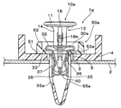
以下、図面を参照して本発明による止め具の一実施形態について説明する。図1,8に示すように、この止め具1は、例えば、車体パネル等の被取付部材2に形成された取付孔3に挿入固定されて、該止め具1を介して、トリムボード等の取付部材4を、前記被取付部材2に取付けるために用いられる。
図1に示すように、この実施形態における止め具1は、ピン10と、該ピン10を受け入れる金属製の板ばね部材30と、両者を保持するグロメット50とを有している。
まず、図2,3及び図6~10を参照して、板ばね部材30について説明する。この板ばね部材30は、一枚の金属板材から形成されるもので、基部31と、該基部31から延設されると共に、自由状態で開き弾性復元力に抗して押圧すると閉じて、互いに係合可能な一対の弾性係合片35,35とを有している。
図3(C)に示すように、基部31は全体として円形状をなし、その中心にはピン10を挿通させるための円形の挿通孔31aが形成されている。また、挿通孔31aの内周には、一対の弾性係合片35,35に対して直交する位置に、一対の切欠き31b,31bが形成されている。各切欠き31bによって、基部31の挿通孔31aの外周の対向する位置に、一対の幅狭部31c,31cが形成され、一対の弾性係合片35,35が撓むときに、基部31が一対の幅狭部31c,31cで屈曲するように構成されている(図2(B)参照)。
上記基部31の、切欠き31b,31bに直交する両側部からは、所定幅の帯状片が突出し、これが内方に向けて折り返されて、図3(A)に示すように、側方から見たときに略U字状に屈曲した屈曲部33,33が形成されている。この屈曲部33,33に各弾性係合片35の基端部がそれぞれ連結されている。U字状の屈曲部33は、これに連結された弾性係合片35,35の弾性復元力を向上させる役割を果たす。
一対の弾性係合片35,35の基端部は、上記U字状の屈曲部33から基部31に対して所定角度で立ち上がって伸びており、同基端部の幅方向両側には、抜け止め爪36,36が外方に向かって切り起こされている。この抜け止め爪36,36は、後述するグロメット50の挿通口53の裏側周縁に係合して、板ばね部材30の抜け止めをなすものである(図7~9参照)。
また、両弾性係合片35,35の軸方向途中の中間部は、互いに遠ざかるように斜め外方に屈曲しており、弾性係合片35,35が開いたときに取付孔3の裏側周縁に係合し、弾性係合片35,35が閉じたときに取付孔3を通過できる係合肩部37をなしている。この係合肩部37は、円形状の取付孔3に対応して、半径方向外方に凸曲面を向けた円弧形状をなしている(図2、図3(B),(C)参照)。
各弾性係合片35の先端部は、それぞれ内側に折り曲げられて折曲部40,40をなしており、更に同折曲部40,40は、図3(B),(C)に示すように、その幅方向に互いにずれた位置に形成され、一対の弾性係合片35,35を互いに近接させて閉じたときに、両折曲部40,40が干渉しないように構成されている。
折曲部40,40の幅方向に隣接した各内側辺には、隣接する他方の折曲部40に向けて、係合突片43,43がそれぞれ突設されている。また、各係合突片43は、弾性係合片35,35を閉じたときに重なる位置に形成されている。そして、弾性係合片片35,35を閉じたときに、図2(B)に示すように、係合突片43,43どうしが係合して、弾性係合片35,35を閉じた状態に保持するようになっている。
なお、係合突片43は、一方の折曲部40のみに形成してもよい。この場合、弾性係合片35,35を閉じると、一方の折曲部40の係合突片43が、他方の折曲部40の内側辺の裏面側(一方の折曲部40の対向面と反対側)に係合して、弾性係合片35,35が閉じることとなる。
各折曲部40の係合突片43よりも前記基部31側(折曲部40の先端側)には、弾性係合片35,35を閉じた状態でピン10が挿入されたときに、ピン10の先端部15(後述)が当接して、同ピン10からの押込力を付与される当接片45が形成されている。この実施形態の場合、当接片45は、折曲部40の先端部分が弾性係合片35の裏面側に向かうように、側方から見て「くの字状」に折曲形成されている。
更に、各当接片45には、ピン10の挿入方向に沿った押込力の向きを、当接片45の幅方向外方への向きに変える当接部がそれぞれ形成されている。この実施形態では、各当接片45の幅方向に隣接する内側辺どうしが、幅方向外方へ向かうと共に、板ばね部材30の基部31側に向かって次第に傾斜する傾斜状内側辺とされ、この傾斜状内側辺が当接部45aをなしている(図2及び図10参照)。これらの当接部45a,45aは、弾性係合片35,35が閉じた状態で、ピン10が挿入されるときに、同ピン10の円錐形状をなした先端部15の外周面に当接するようになっている(図6参照)。
次に、上記構造をなす板ばね部材30に受け入れられるピン10について、図4及び図6~9を参照して説明する。このピン10は、円形状の頭部11と、該頭部11の片面中央から所定長さで延設され、閉じた状態の弾性係合片35,35の間に挿入されたときに、同弾性係合片35,35の係合を解除して開かせると共に、開いた状態の弾性係合片35,35の間に配置され、内側に閉じるのを規制する軸部13とを有している。この軸部13の先端部は、ピン押込時に、当接片45の傾斜状内側辺に当接するテーパ形状をなしている。この実施形態における軸部13は略円柱状をなしていると共に、その先端部15が円錐形状をなしている。そして、図6に示すように、閉じた状態の弾性係合片35,35の当接片45の傾斜面状をなした各当接部45aに、軸部13の先端部15が当接するようになっている。
軸部13の基部側の周方向に対向する2箇所には、所定高さのガイドリブ17,17が軸方向に沿って伸びており、このガイドリブ17,17は、グロメット50にピン10を押し込んでいくときに、グロメット50のスリット56(後述)にそれぞれ嵌入して、ピン10の押し込みガイドとなる。また、軸部13の先端部15より基部側には、ピン10の頭部11が板ばね部材30の挿通孔31a周縁に係合するまで、ピン10が押し込まれたときに、同板ばね部材30の折曲部40が嵌合する、縮径部19が形成されており、その先端側の内面は、先端部15に向かって次第に拡径した逆テーパ面19aをなし、基端側の内面は、先端部15に向かって次第に縮径したテーパ面19bをなしている。
また、縮径部19内周の、ガイドリブ17,17に整合する位置には、板状片21,21が突設されている。そして、ガイドリブ17の先端と、板状片21の先端とには、抜き孔23を介してブリッジ状に連結されて、撓み可能とされた撓み片25が設けられている。この撓み片25の基端側には、係合突部25aが設けられ、先端側には係合爪部25bが設けられている。
係合突部25a及び係合爪部25bは、グロメット50に対してピン10を途中まで押し込んだときに、図7(B)に示すように、グロメット50のベース部51の上下縁部に係合するように配置され、グロメット50に対して、ピン10を抜け止め保持させる。このとき、ピン10は、板ばね部材30の当接片45に押込力を付与しない位置に仮保持される。つまり、この実施形態では、ピン10の係合突部25a及び係合爪部25bと、グロメット50のベース部51とが、本発明における保持手段をなしている。
また、軸部13の撓み片25の内側面に対向する外周面は、ガイドリブ17の突出方向に直交して平面状にカットされ、押圧面27をなしている(図4(A)~(C)参照)。
次に、ピン10及び板ばね部材30を保持するグロメット50について、図1,5を参照して説明する。このグロメット50は、円板状のベース部51と、該ベース部51の裏面側から延出した一対の脚部55,55とを有している。ベース部51の上端外周からは、環状壁52が突出しており、同ベース部51の中心には、ピン10の軸部13及び板ばね部材30の弾性係合片35を挿通させる、円形状の挿通口53が形成されている。また、ベース部51の上面には、挿通口53の中心を通って、所定幅で嵌合凹部54が形成され、これに板ばね部材30の屈曲部33,33が嵌合して回り止めがなされるようになっている。
図1に示すように、一対の脚部55,55は、グロメット50に保持される板ばね部材30の、一対の弾性係合片35,35の撓み方向に直交する方向にそれぞれ配置されている。各脚部55の幅方向中心には、スリット56がその延出方向に沿って形成されている。各脚部55は、スリット56を介して2分割された、ガイド片57,57からなっている。各ガイド片57の内側には、内方に向けて突出する突出部58が設けられており、同ガイド片57の先端外周は、先端に向かって次第に縮径した形状をなしている。
次に、上記構成からなる止め具1の使用方法について説明する。
上述したように、止め具1を構成する板ばね部材30の一対の弾性係合片35,35は、外力を付与していない自由状態では、両者が互いに離れて開いている(図2(A)参照)。この状態から、一対の弾性係合片35,35を弾性復元力に抗して内側に押圧して、両弾性係合片35,35を閉じる。
このとき、折曲部40の各係合突片43,43は、それぞれ整合した位置に設けられているので、両弾性係合片35,35を幅方向に折曲部40,40が互いに離れるようにずらしつつ近接させることにより、一方の係合突片43を、他方の係合突片43の裏面側(一方の係合突片43の対向面とは反対側)に係合させて、弾性係合片35,35を閉じた状態に保持することができる(図2(B)参照)。なお、係合突片43が両折曲部40の一方に形成されている場合には、一方の折曲部40の係合突片43を、他方の折曲部40の内側辺の裏面側(一方の折曲部40の対向面と反対側)に係合させることにより、一対の弾性係合片35,35を閉じた状態に保持することができる。
また、この実施形態においては、板ばね部材30の基部31に形成された挿通孔31aの外周に、一対の弾性係合片35,35の間に位置してかつ対向する位置に一対の幅狭部31c,31cが形成されている。その結果、弾性係合片35,35が撓むときに、図2(B)に示すように、基部31が一対の幅狭部31c,31cで屈曲するようになっているので、弾性係合片35,35どうしを撓みやすくさせることができ、弾性係合片35,35どうしを係合させるときの作業性を向上させると共に、ピン10の押し込みにより弾性係合片35,35どうしの係合を解除させるときの解除動作がスムーズになされる。
次に、弾性係合片35,35を閉じた状態で、板ばね部材30の屈曲部33,33を、グロメット50の嵌合凹部54,54に整合させ、グロメット50の挿通口53に板ばね部材30の弾性係合片35,35を押し込んでいく。すると、グロメット50の脚部55,55の間に、閉じた状態の弾性係合片35,35が挿入され、板ばね部材30を完全に押し込むと、U字状の屈曲部33,33が嵌合凹部54,54に嵌合して回り止めがなされると共に、弾性係合片35に設けた抜け止め爪36,36が、図6に示すように、挿通口53の裏側周縁に係合して、グロメット50に対して板ばね部材30を保持させることができる。
この実施形態においては、グロメット50に板ばね部材30を保持させると、一対の弾性係合片35,35の両側に、グロメット50の一対の脚部55,55がそれぞれ配置されて、その結果、ピン10の、弾性係合片35の撓み方向に直交する方向への動きが規制されるので、ピン10の先端部15を、板ばね部材30の各当接片45,45に確実に押し当てることができる。
次に、グロメット50に対してピン10を仮保持させる。すなわち、グロメット50のスリット56,56及び板ばね部材30の切欠き31b,31bに、ピン10のガイドリブ17,17を整合させて、板ばね部材30の挿通孔31a及びグロメット50の挿通口53を通して、ピンを途中まで押し込む。その結果、係合突部25a及び係合爪部25bがベース部51の上下縁部に係合して、グロメット50にピン10が抜け止め保持される(図7(B)参照)。このとき、図6及び図7(A)に示すように、ピン10の先端部15は、当接片45に押込力を付与せずに、弾性係合片35,35を閉じた状態に保持させるようになっている。
この実施形態においては、上述したように、グロメット50の挿通口53に閉じた状態の弾性係合片35,35を押し込むことにより、グロメット50に板ばね部材30を抜け止め保持させることができると共に、その状態で、ピン10を板ばね部材30の挿通孔31a及びグロメット50の挿通口53を通して押し込むことにより、弾性係合片35が開かない位置で、保持手段(ピン10の係合突部25a及び係合爪部25bと、グロメット50のベース部51)により、グロメット50にピン10を仮保持させることができる。このように、ピン10及び板ばね部材30の他に、両者を保持するグロメット50を備えているので、板ばね部材30とピン10とを、グロメット50を介して予め組付けることができ、取付孔3に固定する際の作業性を向上させることができる。
そして、被取付部材2の取付孔3に、取付部材4の取付孔5を整合させて重ね合わせ(図7参照)、上記工程により組付けた止め具1の先端側を取付孔5から挿入し、グロメット50のベース部51を取付孔5の表側周縁に当接させると共に、板ばね部材30の弾性係合片35の先端側及びグロメット50の脚部55を取付孔3から突出させる。
この実施形態においては、グロメット50の一対の脚部55,55が、取付孔5及び取付孔3に挿入する際の挿入ガイドとなるので、その挿入性を高めることができる。更に、各脚部55は、スリット56に2分割されたガイド片57,57からなり柔軟性が高いので、ガイド性能を保持しつつ、挿入抵抗を低減することができる。
この実施形態においては、自由状態で開いた一対の弾性係合片35,35を、弾性復元力に抗して内側に押圧して閉じ、その状態で互いに係合させることにより、係合肩部37が取付孔3を通過する際に、取付孔3に係合肩部が引っ掛かったり、取付孔内周に弾性係合片35が強く押圧されつつ押し込まれたりすることが抑制され、挿入抵抗を少なくしてスムーズに挿入することができる。
そして、閉じた状態の一対の弾性係合片35,35を開くべく、ピン10を板ばね部材30に対して押し込んでいく。この実施形態では、当接片45の各当接部45aが傾斜面をなすと共に、ピン10の軸部13の先端部15が円錐形状をなしているので、ピン10を押し込んでいくと、ピン10の円錐形状の先端部15が、当接片45の内側辺をなす傾斜状の当接部45aに当接し、該当接片45の当接部45aとピン10の先端部15の円錐面とが摺接しつつ、ピン10が押し込まれていく。
このとき、ピン10の押込力F1(図6参照)が、板ばね部材30の当接片45に設けた当接部45aによって、当接片45を幅方向外方へ押す力に変換される。これについて図6及び図10を参照して更に詳しく説明すると、図6に示すように、板ばね部材30の所定角度で折曲した当接片45,45は、ピン10の円錐形状をなした先端部15の外周に斜め当たりしている。そして、ピン10が押し込まれると、当接片45に設けた傾斜面状の当接部45aに、円錐形状の先端部15が摺接しつつ押し込まれることにより、前記押込力F1が、図10(A)に示すように、当接片45を幅方向外方に押す力F2,F2に変換される。
その結果、図10(B)に示すように、係合突片43,43どうしの係合が解除されて、弾性係合片35,35自体の弾性復元力(同図矢印参照)によって両者が開き、図10(C)に示すように、ピン10が両弾性係合片35,35の間に入り込む。
その結果、図8(A)に示すように、弾性係合片35の各係合肩部37,37が、被取付部材2の取付孔3の裏側周縁に係合すると共に、グロメット50のベース部51が取付部材4の取付孔5の表側周縁に係合して、両者によって被取付部材2及び取付部材4が挟み込まれて、被取付部材2に取付部材4を取付けることができる。このとき、一対の弾性係合片35,35の間にピン10の軸部13が配置されるので、弾性係合片35,35の内側への撓みが規制され、取付孔3からの板ばね部材30の抜け外れが防止される。
この実施形態においては、ピン10の軸部13を、弾性係合片35の折曲部40に向けて押し込むことにより、上述したように、先端部15が折曲部40の当接片45に当接して押込力が付与されると共に、当接部45aにより同押込力が当接片45を幅方向外方へ押す力に変わり、一対の弾性係合片35,35が幅方向に互いに位置ずれして、係合を解除させることができるので、ピン10を押し込むだけの簡単な操作で、閉じた状態の一対の弾性係合片35、35の係合をスムーズに解除させることができ、止め具1の取付け作業性を向上させることができる。
なお、ピン10が押し込まれると、軸部13に設けた押圧面27が、ガイド片57の突出部58に当接して、両脚部55,55が内方から押し広げられ、更に抜け止め力を高めるようになっている(図8(B)参照)。
この実施形態においては、ピン10の軸部13には、ピン10の頭部11を板ばね部材30の挿通孔31aの周縁に係合するまで押し込んだときに、板ばね部材30の折曲部40と嵌合する縮径部19が形成されている。すなわち、上記の止め具1が取付孔に固定された状態で、図8(A)に示すように、折曲部40の屈曲した角部が逆テーパ面19aに係合すると共に、同折曲部40の当接片45がテーパ面19bに係合して、折曲部40が縮径部19に嵌合するようになっているので、板ばね部材30からピン10が抜け外れることを確実に防止することができる。
そして、この止め具1を構成する板ばね部材30の一対の弾性係合片35,35は、自由状態で開き、弾性復元力を伴って取付孔の裏側周縁に係合するようになっているので、取付孔3が形成された被取付部材2の板厚が変化したり、取付孔3の内径が標準寸法よりも大きかったり小さかったりしても、それに柔軟に対応して一対の弾性係合片35,35が弾性的に拡径又は縮径し、係合肩部37,37を取付孔3の裏側周縁に圧接して係合した状態に確実に維持することができ、その結果、取付孔3に対して止め具1を、ガタ付きなくしっかりと固定することができる。
この実施形態においては、当接片45の各当接部45aが傾斜状内側辺をなし、ピン10の軸部13の先端部15がテーパ形状(ここでは円錐形状)をなしている。そのため、取付孔3,5に一対の弾性係合片35,35を挿入した状態で、板ばね部材30の挿通孔31aからピン10を押し込んでいくと、円錐形状の先端部15が傾斜面状の当接部45aに沿って摺接しつつ、ピン10が押し込まれるようになっているので、ピン10の押込力F1(図6参照)を、当接片45を幅方向外方に押す力F2(図10(A)参照)に効率よく変換することができ、一対の弾性係合片35,35の係合解除作業を迅速に行うことができる。
ところで、被取付部材2から取付部材4を取外す場合には、図8(A),(B)に示すように、止め具1が取付孔に固定された状態から、グロメット50の環状壁52と、ピン10の頭部11との間に、例えば、マイナスドライバー等の工具の先端を差し込んで、頭部11の外周縁をこじるようにしてピン10を上方に持ち上げて、ピン10の縮径部19から板ばね部材30の折曲部40を外す(図9(A)参照)。すると、一対の弾性係合片35,35が再び開閉可能となり、その後ピン10を持ち上げることにより、取付孔3,5から止め具1を引き抜いて、被取付部材2から取付部材4を取外すことができる(図9(A),(B)参照)。
なお、この実施形態の止め具1は、ピン10と板ばね部材30とグロメット50とから構成されているが、ピン10及び板ばね部材30から構成されていてもよい。この場合、取付部材の取付孔周縁に、板ばね部材30のU字状の屈曲部33が直接当接することとなる。
図11~18には、本発明による止め具の、他の実施形態が示されている。なお、前記実施形態と実質的に同一部分には同符号を付してその説明を省略する。
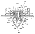
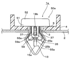
図11に示すように、この実施形態における止め具1aは、前記実施形態と同様に、ピン10a、板ばね部材30a、及びグロメット50aを有している。以下、各部材10a,30a,50aについて、前記実施形態の部材10,30,50とは異なる部分を中心に説明する。
図12,13に示す板ばね部材30aは、スリット状の挿通孔31aが形成された基部31を有している。この挿通孔31aの形成方向に直交して、一対の切欠き31b,31bが形成されている。これらの切欠き31bを介して、基部31の挿通孔31aの外周に、一対の弾性係合片35,35の間に位置し、かつ、対向する位置に一対の幅狭部31c,31cが形成されている。
図13(A)に示すように、各幅狭部31c,31cは、基部31の一対の弾性係合片35,35の撓み方向(矢印B参照)に対して直交する方向(線分C参照)における両側部に配置されており、同基部31を軸方向に見たときに、各弾性係合片35の折曲部40,40が形成されていない幅方向側に偏った位置に、それぞれ形成されている。すなわち、図中、上方の幅狭部31cは、左側の弾性係合片35の折曲部40が形成されていない幅方向側に偏った位置に形成され、下方の幅狭部31cは、右側の弾性係合片35の折曲部40が形成されていない幅方向側に偏って形成されている。
また、前記挿通孔31aは、U字状の屈曲部33の幅方向中央を通って、係合肩部37の手前に至るまで伸びて、弾性係合片35の基部側が切欠かれている。この切欠かれた部分を介して、弾性係合片35の基部側の幅方向中央に、抜け止め爪36が斜め外方に切起こされて形成されている。
各弾性係合片35の先端部に形成された折曲部40,40の、幅方向に隣接した各内側辺からは、隣接する他方の折曲部40に向けて、三角板状の突片が突設されている(図12(B)、図13(A)、図15参照)。この突片の板ばね部材30aの基部側が、ピン10aの先端部15a(後述)が当接して押込力を付与される当接片45をなしており、同突片の板ばね部材30aの先端部側が、弾性係合片35,35を閉じた状態に保持する係合突片43をなしている。
図14(A)に示すピン10aは、軸部13の基部側に、先端部よりも幅広の板状をなす拡径部14が形成されている。この拡径部14は、軸部13が弾性係合片35,35の間に配置されたとき、係合肩部37よりも基部側には当接するが、係合肩部37及びそれよりも先端側には当接しない長さで、軸部先端に向けて延設されている(図17参照)。
また、軸部13の前記拡径部14に直交した両側部には、空隙18aを介して撓み可能な撓み壁部18,18が形成されている。各撓み壁部18には、軸部先端側がテーパ状をなし、基端側に段部が形成された固定突部18b,18bが突設されている。この固定突部18bは、頭部11が挿通孔31a周縁に係合するまで、ピン10aが押し込まれたときに、後述するグロメット50aの係合溝59aの基端部内周に係合するようになっている(図18参照)。すなわち、この固定突部18bが、ピンをグロメットに固定させる固定部をなすと共に、係合溝59aの内周に係合する突部をなしている。
軸部13の先端部15aは、三角板状に形成されており、その両側が頭部11側に向かって次第に幅が広くなるテーパ形状をなしている。この先端部15aの基端両側及び前記拡径部14,14の各先端に、ブリッジ状の撓み片25,25がそれぞれ連結されており、各撓み片25に係合突部25a及び係合爪部25bがそれぞれ形成されている。この係合突部25a及び係合爪部25bが、グロメット50aに対してピン10aを途中まで押し込んだときに、グロメット50aのベース部51の上下縁部に係合して(図15参照)、ピン10aが当接片45に押込力を付与しない位置に仮保持されるようになっている。すなわち、この係合突部25a及び係合爪部25bが、この実施形態における仮保持部をなしている。
図14(B)に示すグロメット50aは、そのベース部51の中央に四角形状の挿通口53a(図15,16参照)が形成されており、この挿通口53aの裏側の対向する両側縁から、一対の弾性係合片35,35の撓み方向であって、同弾性係合片35,35の外側に配置される一対の脚部55a,55aが延設されている(図11,16,17参照)。また、各脚部55a,55aは、その先端どうしが連結されて、先端に向けて縮径した形状(ここでは略V字状)をなしている。各脚部55aの幅方向中央には、同脚部55aの延出方向に沿って長溝55bが形成されている。この長溝55bは、弾性係合片35により脚部55aが内側から押圧されたときに、脚部55aを撓ませやすくさせると共に、グロメット50aに板ばね部材30aを保持させるときに、抜け止め爪36が入り込む部分となる。
前記ベース部51の挿通口53aの、脚部55a,55aに直交する両側縁からは、一対のガイド脚部59,59が延設されている。各ガイド脚部59,59は、弾性係合片35の撓み方向に直交する位置で、かつ、一対の弾性係合片35,35の間にそれぞれ配置されるようになっている。また、各ガイド脚部59には、その軸方向(ガイド脚部59が延出する方向)に沿って係合溝59aがそれぞれ伸びている。そして、頭部11が挿通孔31a周縁に係合するまで、ピン10aが押し込まれたときに、前記係合溝59aの両端部内周に、一対の突部(固定突部18b,係合突部25a)がそれぞれ係合するようになっている(図18参照)。
次に、上記実施形態における止め具1aの使用方法について説明する。
基本的な使用方法については前記実施形態と同様であるので、特徴的な部分を主に説明する。まず、外力が付与されていない自由状態(図12(B)参照)で、互いに離れた一対の弾性係合片35,35を、その弾性復元力に抗して内側に押圧して撓ませる。
この実施形態においては、基部31に設けた各幅狭部31c,31cが、同基部31の弾性係合片35の撓み方向に対して直交する両側部に配置されており、同基部31を軸方向に見たときに、各弾性係合片35の折曲部40が形成されていない幅方向側に偏った位置に、それぞれ形成されている(図13(A)参照)。そのため、一対の弾性係合片35,35を内側に撓ませるときに、図13(A)のラインLを中心にして屈曲し、一方の係合突片43と、他方の係合突片43とが、矢印Dで示すように、幅方向に互いに近づくように移動する。
その結果、一対の係合突片43どうしが互いに近づいて重なり合ってしまうところ、幅方向に広げて係合させることになるので、図13(B)に示す係合状態においても、お互いに幅方向に近づこうとする付勢力が発生し、幅方向に押し合いながら係合した状態になるので、係合がより外れにくくなり、部品搬送時等に、弾性係合片35,35どうしの係合が解除されてしまうことを防止することができる。
その後、一対の弾性係合片35,35を、グロメット50aの一対の脚部55a,55aに整合させ、挿通口53aに押し込むことにより、一対の抜け止め爪36,36が、各脚部55aの長溝55b,55bにそれぞれ入り込むと共に、挿通口53aの裏側周縁に各抜け止め爪36,36が係合して(図16参照)、グロメット50aに板ばね部材30aを保持させることができる。
次いで、板ばね部材30aのスリット状の挿通孔31aの両側に、ピン10aの板状の拡径部14を整合させると共に、同板ばね部材30aの一対の切欠き31b,32bに、ピン10aの一対の撓み壁部18,18を整合させて、ピン10aを所定深さ押し込むことにより、図15に示すように、ベース部51の上下縁部に、係合突部25a及び係合爪部25bがそれぞれ係合して、グロメット50aにピン10aが抜け止め保持される。この状態では、ピン10aの先端部15aのテーパ状の両側辺が、各当接片45の当接部45a,45aにそれぞれ当接するようになっている。
この実施形態においては、ピン10aの軸部13に仮保持部(係合突部25a及び係合爪部25b)と固定部(固定突部18b)とが設けられていることにより、ピン単独でグロメット50aに仮保持させると共に本固定させることができるので、ピン10aを抜け止めするための構造を板ばね部材30aに設ける必要がなくなり、板ばね部材30aの剛性やばね性、弾性復元力等をしっかりと確保することができる。
その後、上記工程で組付けた止め具1を、取付部材4及び被取付部材2の各取付孔5,2に挿入していく。
この実施形態においては、このとき、グロメット50aに設けた、先端が連結された脚部50a及びガイド脚部59がガイドとなるので、グロメット50aを取付孔5,2に引っ掛かることなく、スムーズに挿入することができる。
そして、ベース部51を取付孔5の表側周縁に当接させた後、グロメット50aに対してピン10aを押し込む。すると、三角板状の先端部15aにより、各当接片45,45の係合が解除されて、一対の弾性係合片35,35が開き、その係合肩部37,37によりグロメット50aの脚部55a,55aが内側から押し広げられる。その結果、各弾性係合片35の係合肩部37,37が、脚部55a,55aを介して間接的に、取付孔3の裏側周縁に係合して、止め具1aを介して被取付部材2に取付部材4を取付けることができる(図17参照)。また、この実施形態では、ピン10aの先端部15aが三角板状をなしていて、その両側辺が各当接片45の当接部45a,45aに当接するようになっているので、ピン10aからの押込力が分散することなく、各当接部45a,45aに効率的に作用することとなり、弾性係合片35,35の係合をスムーズに解除することができるようになっている。
また、ピン10aの頭部11が、板ばね部材30aの挿通孔31a周縁に係合するまで押し込まれると、図18に示すように、グロメット50aのガイド脚部59の係合溝59aの基端部内周に固定突部18bが係合する共に、同係合溝59aの先端部内周に係合突部25aが係合し、更にガイド脚部59の先端面周縁に係合爪部25bが係合して、グロメット50aに対してピン10aが固定される。
この実施形態においては、上述したように、ピン10aの頭部11が板ばね部材30aの挿通孔31a周縁に係合するまで押し込まれたときに、ガイド脚部59の係合溝59aの両端部内周に、ピン10aの軸部13に形成された一対の突部(固定突部18b及び係合突部25a)が適度なクリック感を伴って係合するので、グロメット50aに対するピン取付作業が完了したことを、より明確に把握することができる。
この実施形態においては、弾性係合片35,35の外側にグロメット50aの脚部55a,55aが配置されるので、板ばね部材30aの弾性係合片35が取付孔3に直接係合せず、脚部55aを介して間接的に係合することとなる(図17参照)。このように、金属製の板ばね部材30aが取付孔3に直接係合しないようになっているので、板ばね部材30aの錆の発生を防止したり、止め具1aを取付孔3に固定する際や、固定後における異音の発生を抑制したりすることができる。また、取付孔3が形成された部材が金属製の場合には、取付孔周縁での錆の発生も防止することができる。
この実施形態においては、ピン10aの軸部13に上述した形状の拡径部14を設けたことにより、ピン10aの軸部13が弾性係合片35,35の間に配置されたとき、係合肩部37より基部側に拡径部14が当接するので、該基部側において弾性係合片35,35が内側に閉じるのを規制することができ、その結果、取付強度を向上させ、ガタ付きを防止することができる。一方、弾性係合片35の係合肩部37には、拡径部14が当接せず、各弾性係合片35が撓み可能となるので、取付孔が形成された部材の板厚変化に、より柔軟に対応して、止め具をガタ付きなく確実に取付けることができる。
ところで、被取付部材2から取付部材4を取外す際には、ピン10をこじるようにして上方に持ち上げ、ガイド脚部59の係合溝59a内周から一対の突部18b,25aの係合を解除して、弾性係合片35,35の間からピン10aの拡径部14を抜き、図15,16に示す仮保持状態に戻す。すると、拡径部14が抜けて、一対の弾性係合片35,35が再び開閉可能となるので、取付孔3,5から止め具1aを引き抜くことにより、被取付部材2から取付部材4を取外すことができる。
この実施形態においては、このとき、グロメット50aの一対の脚部55a,55aは、その先端どうしが連結され、先端に向けて縮径しているので、止め具1aを取付孔から取り外した後、再度、取付孔に挿入するときに、一対の弾性係合片35,35を閉じて係合突片43どうしで係合させなくても、そのまま押し込んで固定することができ、作業性を向上させることができる。
1,1a 止め具
3,5 取付孔
10 ピン
11 頭部
13 軸部
15 先端部
30,30a 板ばね部材
31 基部
31a 挿通孔
31b 切欠き
31c 幅狭部
35 弾性係合片
36 抜け止め爪
37 係合肩部
40 折曲部
43 係合突片
45 当接片
45a 当接部
50,50a グロメット
51 ベース部
53,53a 挿通口
55,55a 脚部
56 スリット
59 ガイド脚部
59a 係合溝
3,5 取付孔
10 ピン
11 頭部
13 軸部
15 先端部
30,30a 板ばね部材
31 基部
31a 挿通孔
31b 切欠き
31c 幅狭部
35 弾性係合片
36 抜け止め爪
37 係合肩部
40 折曲部
43 係合突片
45 当接片
45a 当接部
50,50a グロメット
51 ベース部
53,53a 挿通口
55,55a 脚部
56 スリット
59 ガイド脚部
59a 係合溝
Claims (13)
- ピンと、該ピンを受け入れる金属製の板ばね部材とを有し、取付孔に固定される止め具であって、
前記板ばね部材は、前記取付孔の表側に係合すると共に、前記ピンの挿通孔を有する基部と、該基部から延設されると共に、自由状態から、その弾性復元力に抗して押圧して閉じたときに互いに係合可能な一対の弾性係合片とを有し、
前記各弾性係合片の軸方向途中には、開いたときに前記取付孔の裏側周縁に前記弾性復元力を伴って係合し、閉じたときに前記取付孔を通過できる係合肩部が形成され、
前記ピンは、頭部と、該頭部から延設された軸部とを有し、該軸部は、閉じた状態の前記一対の弾性係合片の間に挿入されたときに、同一対の弾性係合片の係合を解除して開かせると共に、開いた状態の前記一対の弾性係合片の間に配置されたときに、前記一対の弾性係合片が内側に閉じるのを規制するように構成されていることを特徴とする止め具。 - 前記一対の弾性係合片の各先端は、内側に折曲されて折曲部をなし、各折曲部は幅方向に互いにずれた位置に形成され、
前記各折曲部の幅方向に隣接した内側辺の一方又は両方に係合突片が形成され、前記弾性係合片を閉じたときに、一方の係合突片が他方の内側辺又は他方の係合突片に係合して、前記弾性係合片を閉じた状態に保持できるように構成され、
前記各折曲部の前記係合突片よりも前記基部側には、前記弾性係合片を閉じた状態で前記ピンが挿入されたときに、前記ピンの先端部が当接して押込力を付与される当接片が形成され、該当接片には、前記ピンの挿入方向に沿った押込力を、前記当接片の幅方向外方への押込力に変える当接部がそれぞれ形成され、
前記ピンの軸部は、閉じた状態の前記弾性係合片の間に挿入されたときに、その先端部が前記当接片に当接するように構成されている請求項1記載の止め具。 - 前記折曲部の各当接片は、その先端部分が対応する弾性係合片の裏面側に近づくように折曲されており、
前記各当接片の幅方向に隣接する内側辺どうしは、先端に向かって互いに離れるように幅方向外方へ向かう傾斜状とされ、該傾斜状内側辺が前記当接部をなしており、
前記ピンの軸部の先端部は、ピン押込時に、前記当接片の傾斜状内側辺に当接するテーパ形状をなしている請求項2記載の止め具。 - 前記ピンの軸部には、同ピンの頭部が前記板ばね部材の挿通孔周縁に係合するまで、ピンが押し込まれたときに、前記板ばね部材の折曲部が嵌合する縮径部が形成されている請求項2又は3記載の止め具。
- 前記板ばね部材の基部に形成された挿通孔の外周には、前記一対の弾性係合片の間に位置してかつ対向する位置に一対の幅狭部が形成されており、前記一対の弾性係合片が撓むときに、前記基部が前記一対の幅狭部で屈曲するように構成されている請求項1~4のいずれか1つに記載の止め具。
- 前記板ばね部材の基部に形成された各幅狭部は、同基部の前記一対の弾性係合片の撓み方向に対して直交する両側部に配置されており、同基部を軸方向に見たときに、各弾性係合片の前記折曲部が形成されていない幅方向側に偏った位置に、それぞれ形成されている請求項5記載の止め具。
- 前記ピンの軸部には、前記一対の弾性係合片の間に配置されたとき、同一対の弾性係合片の前記係合肩部よりも基部側に当接するが、該係合肩部及びそれよりも先端側には当接しない拡径部が形成されている請求項1~6のいずれか1つに記載の止め具。
- 前記ピン及び前記板ばね部材の他に、更にグロメットを有しており、
該グロメットは、取付孔の表側周縁に係合するベース部と、該ベース部の裏面側から延出した脚部とを有し、
前記ベース部には、前記板ばね部材の一対の弾性係合片及び前記ピンの軸部を挿通させる挿通口が設けられ、
前記ベース部と前記ピンの軸部との間には、前記挿通孔を通して板ばね部材に挿入されたピンを、前記当接片に押込力を付与しない位置で仮保持する保持手段が設けられ、
前記板ばね部材の一対の弾性係合片には、前記係合肩部よりも基部側に、前記ベース部の挿通口の裏側周縁に係合する抜け止め爪が設けられ、
前記抜け止め爪を前記ベース部の挿通口の裏側周縁に係合させることにより、前記グロメットに前記板ばね部材が保持されると共に、その状態で、前記保持手段により前記グロメットに前記ピンが仮保持されている請求項1~7のいずれか1つに記載の止め具。 - 前記ピンの軸部には、前記板ばね部材の当接片に押込力を付与しない位置で、ピンを前記グロメットに仮保持させる仮保持部と、その頭部が前記板ばね部材の挿通孔周縁に係合するまで、ピンが押し込まれたときに、ピンを前記グロメットに固定させる固定部とが設けられている請求項8記載の止め具。
- 前記グロメットの脚部は、該グロメットに保持される前記板ばね部材の、一対の弾性係合片の撓み方向に対して直交する方向にそれぞれ配置された一対のものからなる請求項8又は9記載の止め具。
- 前記グロメットの脚部は、前記一対の弾性係合片の撓み方向であって、同一対の弾性係合片の外側に配置された一対のものからなる請求項8又は9記載の止め具。
- 前記グロメットの一対の脚部は、その先端どうしが連結されて、先端に向けて縮径した形状をなしている請求項11記載の止め具。
- 前記グロメットには、前記一対の脚部に直交する位置に、軸方向に沿って伸びる係合溝を有するガイド脚部が形成されており、
前記ピンの軸部には、同ピンの頭部が前記板ばね部材の挿通孔周縁に係合するまで、ピンが押し込まれたときに、前記係合溝の両端部内周に係合する一対の突部が形成されている請求項11又は12記載の止め具。
Priority Applications (3)
| Application Number | Priority Date | Filing Date | Title |
|---|---|---|---|
| DE112009001765T DE112009001765T5 (de) | 2008-07-18 | 2009-05-07 | Befestigungselement |
| JP2010520802A JP5036872B2 (ja) | 2008-07-18 | 2009-05-07 | 止め具 |
| US13/054,761 US8636454B2 (en) | 2008-07-18 | 2009-05-07 | Fastener |
Applications Claiming Priority (2)
| Application Number | Priority Date | Filing Date | Title |
|---|---|---|---|
| JP2008-186919 | 2008-07-18 | ||
| JP2008186919 | 2008-07-18 |
Publications (1)
| Publication Number | Publication Date |
|---|---|
| WO2010007828A1 true WO2010007828A1 (ja) | 2010-01-21 |
Family
ID=41550237
Family Applications (1)
| Application Number | Title | Priority Date | Filing Date |
|---|---|---|---|
| PCT/JP2009/058623 Ceased WO2010007828A1 (ja) | 2008-07-18 | 2009-05-07 | 止め具 |
Country Status (4)
| Country | Link |
|---|---|
| US (1) | US8636454B2 (ja) |
| JP (1) | JP5036872B2 (ja) |
| DE (1) | DE112009001765T5 (ja) |
| WO (1) | WO2010007828A1 (ja) |
Cited By (8)
| Publication number | Priority date | Publication date | Assignee | Title |
|---|---|---|---|---|
| WO2012117947A1 (ja) * | 2011-03-02 | 2012-09-07 | 株式会社ニフコ | クリップ |
| WO2013080776A1 (ja) * | 2011-12-02 | 2013-06-06 | スガツネ工業株式会社 | 締結装置 |
| JP2013253626A (ja) * | 2012-06-05 | 2013-12-19 | Piolax Inc | 留め具 |
| JP2014505845A (ja) * | 2011-02-02 | 2014-03-06 | アー ライモント エ カンパニュイ | 固定装置 |
| WO2016006328A1 (ja) * | 2014-07-08 | 2016-01-14 | 株式会社パイオラックス | 止め具 |
| CN105909631A (zh) * | 2013-07-15 | 2016-08-31 | Bjb两合公司 | 紧固元件、布置系统和用于使两个构件相互紧靠的方法 |
| CN109339122A (zh) * | 2018-10-29 | 2019-02-15 | 佛山科学技术学院 | 一种防止脱落的应变计预埋件 |
| JP2019183464A (ja) * | 2018-04-06 | 2019-10-24 | Ykk Ap株式会社 | 装飾材取付部材および建具 |
Families Citing this family (42)
| Publication number | Priority date | Publication date | Assignee | Title |
|---|---|---|---|---|
| JP5221759B2 (ja) * | 2009-06-29 | 2013-06-26 | 株式会社ニフコ | クリップ、及びクリップ装置 |
| CA2768039C (en) * | 2009-07-24 | 2017-09-12 | Pem Management, Inc. | Quick acting panel fastener |
| WO2011031806A1 (en) * | 2009-09-09 | 2011-03-17 | The Monadnock Company | Panel fastener, panel assembly and methods of assembly and installation |
| BE1020453A3 (nl) * | 2011-12-01 | 2013-10-01 | Unilin Bvba | Meubel en werkwijze voor het vervaardigen van meubels. |
| JP6147525B2 (ja) * | 2013-03-04 | 2017-06-14 | 大和化成工業株式会社 | 結合クリップ |
| DE102013005830A1 (de) * | 2013-04-04 | 2014-10-09 | Iwis Motorsysteme Gmbh & Co. Kg | Gleitschiene zum Spannen und Führen eines Endlostriebmittels und Verfahren zum Herstellen der Gleitschiene |
| DE102013011713A1 (de) * | 2013-07-15 | 2015-01-15 | Bjb Gmbh & Co. Kg | Befestigungsmittel |
| DE102013011714A1 (de) * | 2013-07-15 | 2015-01-15 | Bjb Gmbh & Co. Kg | Befestigungsmittel |
| FR3020098B1 (fr) * | 2014-04-22 | 2017-05-05 | A Raymond Et Cie | Dispositif de fixation par cramponnage |
| DE102014115186B3 (de) * | 2014-10-17 | 2016-02-18 | Trw Automotive Electronics & Components Gmbh | Befestigungselement sowie Baugruppe mit einem solchen Befestigungselement und einem Aufnahmeelement |
| DE102015106223B4 (de) | 2015-04-22 | 2024-09-12 | Illinois Tool Works Inc. | System zur Befestigung eines Türmoduls an einer Automobiltür |
| US10012253B2 (en) * | 2015-04-24 | 2018-07-03 | Fca Us Llc | Self-adjusting bracket assembly and installation method |
| DE102015209881A1 (de) * | 2015-05-29 | 2016-12-01 | A.RAYMOND et Cie. SCS | Vorrichtung zum Halten eines Bauteils |
| WO2017021427A1 (de) * | 2015-08-03 | 2017-02-09 | Johnson Controls Gmbh | Anschlag für eine schiene eines längsverschiebbaren sitzes |
| KR102020162B1 (ko) * | 2015-08-25 | 2019-09-09 | 헬러만타이톤 코포레이션 | 블라인드 홀 마운트 |
| DE102015117007B3 (de) * | 2015-10-06 | 2017-03-30 | Bjb Gmbh & Co. Kg | Befestigungselement |
| JP2017115978A (ja) * | 2015-12-24 | 2017-06-29 | 大和化成工業株式会社 | クリップ |
| US9879803B2 (en) * | 2016-01-14 | 2018-01-30 | Maxdao Limited | Connectable cable organizer |
| CN109073267A (zh) | 2016-03-03 | 2018-12-21 | 开利公司 | 紧固系统及包括这种紧固系统的空气处理单元 |
| US9850934B2 (en) | 2016-03-07 | 2017-12-26 | A. Raymond Et Cie | Self-reinforcing clip |
| DE102016004336A1 (de) * | 2016-04-13 | 2017-10-19 | A.RAYMOND et Cie. SCS | Clip zum Befestigen eines Elements an einem anderen Element und Verwendung eines solchen zweiteiligen Clips |
| US11692570B2 (en) | 2016-11-04 | 2023-07-04 | Newfrey Llc | Pin and grommet fastener accommodating two directional offset and related methods |
| US10288098B2 (en) | 2016-11-04 | 2019-05-14 | Newfrey Llc | Pin and grommet fastener accommodating two directional offset and related methods |
| DE102016014628A1 (de) * | 2016-12-09 | 2018-06-14 | A.RAYMOND et Cie. SCS | Clip zum Befestigen eines ersten Elements an einem zweiten Element |
| US10590968B2 (en) * | 2018-03-01 | 2020-03-17 | Newfrey Llc | Dual component U-base fastener |
| US10894516B2 (en) | 2017-10-18 | 2021-01-19 | Newfrey Llc | U-base fastener with folded barb and multiple spring arms |
| US10900514B2 (en) | 2017-11-07 | 2021-01-26 | Hellermanntyton Corporation | Wire-tray-assembly with stud-mount inserts |
| US10408248B1 (en) | 2018-09-05 | 2019-09-10 | Newfrey Llc | Sealing pin and grommet fastener accommodating two directional offset |
| CN109764047B (zh) * | 2019-03-08 | 2020-12-04 | 靖江市凯狄五金机械制造有限公司 | 一种组合铆钉 |
| DE102019135611A1 (de) | 2019-12-20 | 2021-06-24 | Böllhoff Verbindungstechnik GmbH | Halteklammer eines Schnellverschlusses, ein Schnellverschluss sowie eine Bauteilverbindung mit diesem Schnellverschluss |
| DE102020204176A1 (de) * | 2020-03-31 | 2021-09-30 | Witte Automotive Gmbh | Befestigungselement |
| TWI722932B (zh) * | 2020-06-24 | 2021-03-21 | 簡文豐 | 適用於鎖孔之安全鉸鎖裝置 |
| US12146522B2 (en) * | 2020-12-08 | 2024-11-19 | The Boeing Company | Fastener insert for a composite sandwich panel, a panel assembly, and a method of fastening a component to a composite sandwich panel |
| US11451025B2 (en) | 2020-12-22 | 2022-09-20 | Hellermann Tyton Corporation | Wire tray and mounting insert assemblies |
| US11746812B2 (en) | 2021-05-12 | 2023-09-05 | Newfrey Llc | Dual component sealing fastener and coupling assembly including same |
| DE102023101414A1 (de) * | 2022-02-11 | 2023-08-17 | Illinois Tool Works Inc. | Befestigungsvorrichtung sowie ein Befestigungssystem zum Befestigen eines Bauteils an einem Bolzen eines Trägerbauteils |
| US12322945B2 (en) | 2022-05-11 | 2025-06-03 | Lear Corporation | Cable retainer and method |
| US12255446B2 (en) | 2022-05-11 | 2025-03-18 | Lear Corporation | Cable retainer and method |
| US12338848B2 (en) | 2022-06-30 | 2025-06-24 | Hellermanntyton Corporation | Anti-wobble fir tree mount |
| US12551814B1 (en) * | 2022-10-31 | 2026-02-17 | Imaginnoodles, Llc | Fasteners for foam construction elements |
| GB202313813D0 (en) * | 2023-09-11 | 2023-10-25 | Illinois Tool Works | Fastening clip |
| US20250361899A1 (en) * | 2024-05-24 | 2025-11-27 | The Boeing Company | Twist-lock fasteners, assemblies, and methods for fastening |
Citations (4)
| Publication number | Priority date | Publication date | Assignee | Title |
|---|---|---|---|---|
| JPS62170410U (ja) * | 1986-04-18 | 1987-10-29 | ||
| JPH109237A (ja) * | 1996-06-21 | 1998-01-13 | Piolax Inc | クリップ |
| JP2002227814A (ja) * | 2001-01-30 | 2002-08-14 | Mitsubishi Electric Corp | スナップフィット結合構造 |
| JP2007315467A (ja) * | 2006-05-24 | 2007-12-06 | Piolax Inc | 部品の取付装置 |
Family Cites Families (10)
| Publication number | Priority date | Publication date | Assignee | Title |
|---|---|---|---|---|
| US4630338A (en) * | 1985-12-19 | 1986-12-23 | Usm Corporation | Molding clip |
| JPH0310408Y2 (ja) * | 1987-02-28 | 1991-03-14 | ||
| US5100273A (en) * | 1990-09-06 | 1992-03-31 | Eustathios Vassiliou | Expansion fastening system with quick lock and release |
| DE4032565C2 (de) * | 1990-10-13 | 1994-08-18 | Camloc Gmbh | Vorrichtung zum lösbaren Verbinden zweier Bauteile |
| US5636891A (en) * | 1995-06-07 | 1997-06-10 | Prince Corporation | Adjustable fastener |
| US7178850B2 (en) * | 2005-02-09 | 2007-02-20 | Termax Corporation | Tethered fastener apparatus and method |
| FR2853367B1 (fr) * | 2003-04-03 | 2005-06-24 | Lisi Automotive Rapid | Dispositif de fixation, notamment de maintien d'un empilement d'au moins deux panneaux |
| US6976292B2 (en) * | 2003-08-28 | 2005-12-20 | Newfrey Llc | Resilient clip fastener |
| US7178205B2 (en) * | 2004-08-10 | 2007-02-20 | Newfrey Llc | Multiple engagement joint tethered fastener |
| JP2006088985A (ja) * | 2004-09-27 | 2006-04-06 | Toyoda Gosei Co Ltd | 頭部保護エアバッグ装置 |
-
2009
- 2009-05-07 US US13/054,761 patent/US8636454B2/en not_active Expired - Fee Related
- 2009-05-07 WO PCT/JP2009/058623 patent/WO2010007828A1/ja not_active Ceased
- 2009-05-07 DE DE112009001765T patent/DE112009001765T5/de not_active Ceased
- 2009-05-07 JP JP2010520802A patent/JP5036872B2/ja not_active Expired - Fee Related
Patent Citations (4)
| Publication number | Priority date | Publication date | Assignee | Title |
|---|---|---|---|---|
| JPS62170410U (ja) * | 1986-04-18 | 1987-10-29 | ||
| JPH109237A (ja) * | 1996-06-21 | 1998-01-13 | Piolax Inc | クリップ |
| JP2002227814A (ja) * | 2001-01-30 | 2002-08-14 | Mitsubishi Electric Corp | スナップフィット結合構造 |
| JP2007315467A (ja) * | 2006-05-24 | 2007-12-06 | Piolax Inc | 部品の取付装置 |
Cited By (14)
| Publication number | Priority date | Publication date | Assignee | Title |
|---|---|---|---|---|
| JP2014505845A (ja) * | 2011-02-02 | 2014-03-06 | アー ライモント エ カンパニュイ | 固定装置 |
| WO2012117947A1 (ja) * | 2011-03-02 | 2012-09-07 | 株式会社ニフコ | クリップ |
| WO2013080776A1 (ja) * | 2011-12-02 | 2013-06-06 | スガツネ工業株式会社 | 締結装置 |
| JPWO2013080776A1 (ja) * | 2011-12-02 | 2015-04-27 | スガツネ工業株式会社 | 締結装置 |
| JP2013253626A (ja) * | 2012-06-05 | 2013-12-19 | Piolax Inc | 留め具 |
| CN105909631A (zh) * | 2013-07-15 | 2016-08-31 | Bjb两合公司 | 紧固元件、布置系统和用于使两个构件相互紧靠的方法 |
| WO2016006328A1 (ja) * | 2014-07-08 | 2016-01-14 | 株式会社パイオラックス | 止め具 |
| JPWO2016006328A1 (ja) * | 2014-07-08 | 2017-04-27 | 株式会社パイオラックス | 止め具 |
| CN106715929A (zh) * | 2014-07-08 | 2017-05-24 | 百乐仕株式会社 | 固定件 |
| US9982700B2 (en) | 2014-07-08 | 2018-05-29 | Piolax, Inc. | Fastener |
| CN106715929B (zh) * | 2014-07-08 | 2019-03-01 | 百乐仕株式会社 | 固定件 |
| JP2019183464A (ja) * | 2018-04-06 | 2019-10-24 | Ykk Ap株式会社 | 装飾材取付部材および建具 |
| JP7012582B2 (ja) | 2018-04-06 | 2022-01-28 | Ykk Ap株式会社 | 装飾材取付部材および建具 |
| CN109339122A (zh) * | 2018-10-29 | 2019-02-15 | 佛山科学技术学院 | 一种防止脱落的应变计预埋件 |
Also Published As
| Publication number | Publication date |
|---|---|
| US20110116890A1 (en) | 2011-05-19 |
| US8636454B2 (en) | 2014-01-28 |
| DE112009001765T5 (de) | 2011-08-25 |
| JP5036872B2 (ja) | 2012-09-26 |
| JPWO2010007828A1 (ja) | 2012-01-05 |
Similar Documents
| Publication | Publication Date | Title |
|---|---|---|
| JP5036872B2 (ja) | 止め具 | |
| JP5231333B2 (ja) | 止め具 | |
| JP5027919B2 (ja) | クリップ | |
| JP5628912B2 (ja) | 速作業性パネル締め具 | |
| JP4067341B2 (ja) | 2ピースクリップ | |
| JP6255033B2 (ja) | 止め具 | |
| JP4560384B2 (ja) | 自動車内装部品の取付け装置 | |
| JP2009008249A (ja) | 2ピースクリップ | |
| KR20070114039A (ko) | 2피스 클립 | |
| JP5081980B2 (ja) | クリップと取付部材との組付構造 | |
| JP2009008225A (ja) | 留め具 | |
| JP5319586B2 (ja) | 部品の締結構造及びこれに用いるクリップ | |
| WO2009093496A1 (ja) | クリップ | |
| JP2007211918A (ja) | 部品の取付け装置 | |
| JP2007315467A (ja) | 部品の取付装置 | |
| JP2010112508A (ja) | 押込みタイプの固定具 | |
| JP2014228031A (ja) | 取付部材の取付構造 | |
| JP5210207B2 (ja) | クリップと取付部材との組付構造 | |
| JP2006220180A (ja) | 部材ロック構造 | |
| JP5922992B2 (ja) | 留め具 | |
| JP4675847B2 (ja) | 2ピースクリップ | |
| JP5095550B2 (ja) | クリップ | |
| JP2006057647A (ja) | 車両用アクセサリの固定装置 | |
| JP2010151223A (ja) | 高強度ワンプッシュクリップ | |
| JP2019100440A (ja) | プラスチックファスナー |
Legal Events
| Date | Code | Title | Description |
|---|---|---|---|
| 121 | Ep: the epo has been informed by wipo that ep was designated in this application |
Ref document number: 09797756 Country of ref document: EP Kind code of ref document: A1 |
|
| WWE | Wipo information: entry into national phase |
Ref document number: 2010520802 Country of ref document: JP |
|
| WWE | Wipo information: entry into national phase |
Ref document number: 13054761 Country of ref document: US |
|
| 122 | Ep: pct application non-entry in european phase |
Ref document number: 09797756 Country of ref document: EP Kind code of ref document: A1 |