WO2010004671A1 - アンテナ装置 - Google Patents
アンテナ装置 Download PDFInfo
- Publication number
- WO2010004671A1 WO2010004671A1 PCT/JP2009/001231 JP2009001231W WO2010004671A1 WO 2010004671 A1 WO2010004671 A1 WO 2010004671A1 JP 2009001231 W JP2009001231 W JP 2009001231W WO 2010004671 A1 WO2010004671 A1 WO 2010004671A1
- Authority
- WO
- WIPO (PCT)
- Prior art keywords
- antenna
- top portion
- base
- substrate
- view
- Prior art date
Links
Images


Classifications
-
- H—ELECTRICITY
- H01—ELECTRIC ELEMENTS
- H01Q—ANTENNAS, i.e. RADIO AERIALS
- H01Q1/00—Details of, or arrangements associated with, antennas
- H01Q1/27—Adaptation for use in or on movable bodies
- H01Q1/32—Adaptation for use in or on road or rail vehicles
-
- H—ELECTRICITY
- H01—ELECTRIC ELEMENTS
- H01Q—ANTENNAS, i.e. RADIO AERIALS
- H01Q1/00—Details of, or arrangements associated with, antennas
- H01Q1/36—Structural form of radiating elements, e.g. cone, spiral, umbrella; Particular materials used therewith
-
- H—ELECTRICITY
- H01—ELECTRIC ELEMENTS
- H01Q—ANTENNAS, i.e. RADIO AERIALS
- H01Q1/00—Details of, or arrangements associated with, antennas
- H01Q1/27—Adaptation for use in or on movable bodies
- H01Q1/32—Adaptation for use in or on road or rail vehicles
- H01Q1/325—Adaptation for use in or on road or rail vehicles characterised by the location of the antenna on the vehicle
- H01Q1/3275—Adaptation for use in or on road or rail vehicles characterised by the location of the antenna on the vehicle mounted on a horizontal surface of the vehicle, e.g. on roof, hood, trunk
-
- H—ELECTRICITY
- H01—ELECTRIC ELEMENTS
- H01Q—ANTENNAS, i.e. RADIO AERIALS
- H01Q1/00—Details of, or arrangements associated with, antennas
- H01Q1/12—Supports; Mounting means
- H01Q1/22—Supports; Mounting means by structural association with other equipment or articles
- H01Q1/24—Supports; Mounting means by structural association with other equipment or articles with receiving set
-
- H—ELECTRICITY
- H01—ELECTRIC ELEMENTS
- H01Q—ANTENNAS, i.e. RADIO AERIALS
- H01Q1/00—Details of, or arrangements associated with, antennas
- H01Q1/42—Housings not intimately mechanically associated with radiating elements, e.g. radome
-
- H—ELECTRICITY
- H01—ELECTRIC ELEMENTS
- H01Q—ANTENNAS, i.e. RADIO AERIALS
- H01Q21/00—Antenna arrays or systems
- H01Q21/30—Combinations of separate antenna units operating in different wavebands and connected to a common feeder system
-
- H—ELECTRICITY
- H01—ELECTRIC ELEMENTS
- H01Q—ANTENNAS, i.e. RADIO AERIALS
- H01Q5/00—Arrangements for simultaneous operation of antennas on two or more different wavebands, e.g. dual-band or multi-band arrangements
-
- H—ELECTRICITY
- H01—ELECTRIC ELEMENTS
- H01Q—ANTENNAS, i.e. RADIO AERIALS
- H01Q9/00—Electrically-short antennas having dimensions not more than twice the operating wavelength and consisting of conductive active radiating elements
- H01Q9/04—Resonant antennas
- H01Q9/30—Resonant antennas with feed to end of elongated active element, e.g. unipole
- H01Q9/32—Vertical arrangement of element
- H01Q9/36—Vertical arrangement of element with top loading
Definitions
- the present invention relates to a low-profile antenna device attached to a vehicle capable of receiving AM broadcast and FM broadcast.
- a conventional antenna device attached to a vehicle is generally an antenna device capable of receiving AM broadcast and FM broadcast.
- a rod antenna having a length of about 1 m has been conventionally used to receive AM broadcast and FM broadcast.
- the length of this rod antenna is about 1 ⁇ 4 wavelength in the FM wave band, but in the AM wave band, the length is much shorter than the wavelength, so the sensitivity is significantly reduced.
- a high impedance cable is used to increase the impedance of the rod antenna with respect to the AM wave band, or amplification is performed using an AM wave band amplifier to ensure sensitivity.
- a vehicle-mounted antenna device in which the length of the antenna is shortened to about 180 mm to 400 mm by using a helical antenna in which the rod portion of the antenna is helically wound.
- an amplifier is inserted directly under the antenna in order to compensate for the performance deterioration due to the reduction of the rod portion.
- FIG. 70 is a side view showing the configuration of a conventional antenna device 100 in which the rod portion is shortened.
- a conventional antenna device 100 shown in FIG. 70 includes an element 110 and an antenna base 111 to which a lower end of the element 110 is rotatably attached within a predetermined angle range.
- the antenna base 111 includes an antenna cover and an antenna base.
- An amplifier and a matching circuit are built in the antenna cover, and the antenna base is fitted on the lower surface of the antenna cover.
- a bolt portion for attaching the antenna device 100 to the vehicle body protrudes from the lower surface of the antenna base.
- the antenna device 1 is an antenna that receives AM broadcast and FM broadcast.
- the length of the element 110 is about 180 mm, and the total height h100 from the lower surface of the antenna base 111 to the tip of the element 110 is about 195 mm.
- the element 110 includes a helical element and an element cover that covers the helical element. Further, in the antenna device 100, a side view showing a state in which the height 110 from the lower surface of the antenna base 111 to the tip of the element 110 is about 70 mm by rotating the element 110 in a direction perpendicular to the antenna base 111. 71. JP-A-2005-223957 JP2003-188619
- the height of the antenna device protruding from the vehicle is limited to a height of 70 mm or less by the vehicle external protrusion regulation, and the length in the longitudinal direction is preferably about 160 to 220 mm so as not to impair the appearance of the vehicle. .
- the radiation resistance Rrad of such an antenna is substantially determined in proportion to the square of the height of the antenna as expressed as 600 to 800 ⁇ (height / wavelength) 2 .
- the sensitivity deteriorates by about 7 dB.
- an object of the present invention is to provide an antenna device capable of receiving AM broadcast and FM broadcast that can suppress sensitivity deterioration as much as possible even when the posture is low at 70 mm or less.
- the present invention is an antenna device that includes an antenna case and an antenna portion that is housed in the antenna case, and projects at a height of about 70 mm or less when attached.
- An antenna substrate having an antenna pattern formed thereon is erected on an antenna base that is fitted to the lower end of the antenna case, and a top portion having a mountain-shaped cross section is disposed so as to straddle the antenna substrate.
- the distance between the lower edge of the side portion which is the slope of the top portion and the antenna base is about 10 mm or more, and the size of the top portion is about 3 pF or more of the antenna capacity of the antenna element composed of the top portion and the antenna pattern.
- the main feature is that it is a large size.
- the cross-sectional shape of the top portion is formed in a mountain shape, the facing area between the side portion which is the slope of the top portion and the antenna base can be reduced as much as possible.
- the reactive capacity component in the capacity can be reduced as much as possible.
- the distance between the lower edge of the side portion, which is the slope of the top portion, and the antenna base is about 10 mm or more, and the antenna capacity of the antenna element including the top portion and the antenna pattern is about 3 pF or more.
- connection metal fitting concerning the antenna apparatus of this invention.
- front view which shows the structure of the connection metal fitting concerning the antenna apparatus of this invention.
- side view which shows the structure of the connection metal fitting concerning the antenna apparatus of this invention.
- front view which shows the structure of the antenna board
- side view which shows the structure of the antenna board
- FIG. 10 is still another diagram showing a change characteristic of the S / N ratio in the AM wave band when the rearward movement amount L of the top portion from the standard position is changed and moved backward. It is a figure which shows the change characteristic of the S / N ratio in the FM wave band at the time of changing back movement amount L of the top part from a standard position, and moving back. It is another figure which shows the change characteristic of S / N ratio in the FM wave band at the time of changing back movement amount L of the top part from a standard position, and moving back.
- FIG. 10 is still another diagram showing a change characteristic of the S / N ratio in the AM wave band when the rearward movement amount L of the top portion from the standard position is changed and moved backward. It is a figure which shows the change characteristic of the S / N ratio in the FM wave band at the time of changing back movement amount L of the top part from a standard position, and moving back. It is another figure which shows the change characteristic of S / N ratio in the FM wave band at the time of changing back movement
- FIG. 11 is still another diagram showing the change characteristic of the S / N ratio in the FM wave band when the rearward movement amount L of the top portion from the standard position is changed and moved backward.
- It is a right view which shows the structure of the antenna apparatus used for the basic experiment which changes the height from the antenna base of a top part.
- It is a front view which shows the structure of the antenna apparatus used for the basic experiment which changes the height from the antenna base of a top part.
- FIG. 12 is still another diagram showing the change characteristic of the S / N ratio in the AM wave band when the height of the top portion is gradually increased.
- FIG. 10 is still another diagram showing the change characteristic of the S / N ratio in the FM wave band when the height of the top portion is gradually increased. It is the front view and side view which show the 1st structure used for the basic experiment of the antenna capacity
- antenna device 10 antenna case, 20 antenna base, 20a body part, 20b antenna mounting part, 20c screw hole, 20d screw part, 20e boss, 20f insertion hole, 20g rectangular hole, 20h cable lead hole, 20i rectangular hole, 21 Bolt part, 22 cable, 24 base pad, 24a body part, 24b peripheral wall part, 24c notch hole, 24d hole part, 30 antenna board, 30a board body, 30b antenna pattern, 30c pattern, 30d mounting hole, 30e long hole, 30f Projection, 30g hole, 30h protrusion, 30i notch, 31 top part, 31a first side, 31b second side, 31c contact piece, 31d screw hole, 31e flat part, 31f slit, 32 GPS antenna, 33 connection Line, 33 Body part, 33b U-shaped part, 33c U-shaped part, 33d bent part, 34 amplifier board, 34a board body, 34b screw hole, 34b insertion hole, 35 coil, 35a coil body, 35b lead wire, 36 connection fitting , 36a metal fitting body, 36b contact piece
- FIGS. 1 is a plan view showing the configuration of the antenna device 1 according to the present invention
- FIG. 2 is a front view showing the configuration of the antenna device 1 according to the present invention
- FIG. 3 is the antenna device 1 according to the present invention.
- 4 is a plan view showing the internal configuration of the antenna device 1 according to the present invention.
- FIG. 5 is a front view showing the internal configuration of the antenna device 1 according to the present invention.
- 6 is a right side view showing the internal configuration of the antenna device 1 according to the present invention.
- the antenna device 1 is an antenna device attached to the roof of a vehicle, and the height h protruding from the vehicle when attached to the vehicle is about 70 mm. Yes.
- the antenna device 1 has an extremely low attitude (the height h is about 0.0023 ⁇ or less when the wavelength of the frequency of 100 MHz is ⁇ ), but can receive AM broadcast and FM broadcast.
- the antenna device 1 has a streamlined shape that becomes thinner toward the tip, and can be freely determined within a certain range so as not to impair the aesthetics and design of the vehicle.
- a flexible base pad made of rubber or elastomer is fitted on the lower surface of the antenna device 1 so that it can be attached to the vehicle in a watertight manner.
- An antenna device 1 is attached to a resin antenna case 10, a metal antenna base 20 to which a lower portion of the antenna case 10 is fitted, and the antenna base 20 vertically.
- the antenna board 30 and the amplifier board 34 attached in parallel, the top part, and the side part formed into a slope from both sides of the top part are formed in a cross-sectional shape, and are arranged on top so as to straddle the antenna board 30 And a GPS antenna 32 mounted on the antenna base 20.
- the antenna case 10 is made of a radio wave transmitting synthetic resin, and has a streamlined outer shape that becomes thinner toward the tip.
- the antenna case 10 there are formed a space in which the upright antenna substrate 30 and the top portion 31 disposed on the antenna substrate 30 can be stored, and a space in which the amplifier substrate 34 is stored in the horizontal direction.
- a metal antenna base 20 is fitted on the lower surface of the antenna case 10.
- An antenna substrate 30 is erected and fixed to the antenna base 20, and an amplifier substrate 34 is fixed substantially parallel to the antenna base 20 in front of the antenna substrate 30.
- an antenna pattern is formed on the upper portion of the antenna substrate 30.
- a top portion 31 is built in the upper portion of the antenna case 10.
- the top portion 31 built in the antenna case 10 is disposed so as to straddle the upper portion of the antenna substrate 30, and the connection fitting attached to the upper portion of the antenna substrate 30. 36 comes into electrical contact with the inner surface of the top portion 31. Since the connection fitting 36 is electrically connected to the antenna pattern formed on the antenna substrate 30, the top portion 31 and the antenna pattern are connected via the connection fitting 36. As a result, an antenna element is constituted by the antenna pattern and the top portion 31, and the antenna substrate 30, the top portion 31, and the amplifier substrate 34 are accommodated in the space inside the antenna case 10.
- a coil 35 for resonating an antenna element constituted by an antenna pattern and a top portion 31 in the vicinity of the FM waveband is provided on the antenna substrate 30, a coil 35 for resonating an antenna element constituted by an antenna pattern and a top portion 31 in the vicinity of the FM waveband is provided.
- One end of the coil 35 is connected to the antenna pattern
- the other end of the coil 35 is connected to one end of the pattern formed on the antenna substrate 30, and one end of the connection line 33 is connected to the other end of the pattern.
- the other end of the connection line 33 is connected to an input portion of an AM / FM amplifier provided on the amplifier board 34, and an AM / FM reception signal received by an antenna element constituted by the antenna pattern and the top portion 31 is AM.
- the signal is input to the / FM amplifier and amplified.
- a bolt portion 21 for attaching the antenna device 1 to the vehicle is formed so as to protrude from the lower surface of the antenna base 20.
- a cable 22 for guiding a received signal from the antenna device 1 into the vehicle is led out from the lower surface of the antenna base 20.
- the cable 22 is led out from the amplifier board 34 and includes a cable for guiding the AM reception signal and the FM reception signal amplified by the AM / FM amplifier provided on the amplifier board 34, and is bundled by a collar 45. ing.
- holes through which the bolt part 21 and the cable 22 are inserted are formed in the roof of the vehicle, and the antenna device 1 is placed on the roof so that the bolt part 21 and the cable 22 are inserted into these holes.
- the antenna device 1 can be fixed to the roof of the vehicle by fastening a nut to the bolt portion 21 protruding into the vehicle. Further, power to the amplifier board 34 accommodated in the antenna case 10 is supplied to the amplifier board 34 from the inside of the vehicle via the cable 22.
- FIG. 7 An exploded view of the antenna device 1 according to the present invention is shown in FIG. The assembly of the antenna device 1 according to the present invention will be described with reference to FIG. 7.
- the top portion 31 is fixed to the upper part of the antenna case 10 with two screws 40.
- a connection fitting 36 is fitted to the upper end of the antenna substrate 30.
- the connection fitting 36 is attached to the upper portion of the antenna substrate 30 by sandwiching the antenna substrate 30.
- a coil 35 is soldered on the antenna substrate 30 and attached.
- the antenna substrate 30 is erected and fixed to the antenna base 20 with two screws 41.
- the amplifier board 34 is disposed in front of the antenna board 30 and is fixed to the antenna base 20 substantially in parallel by three screws 42.
- a cable 22 for outputting amplified AM reception signals and FM reception signals is led out from the amplifier board 34, and a terminal 43 is attached to the tip of the cable 22, and the terminal 43 is fixed to the back surface of the amplifier board 34. Further, one end of a wire-like connection line 33 is connected to the antenna substrate 30, and the other end of the connection line 33 is connected to the amplifier substrate 34, whereby the output end of the coil 35 provided on the antenna substrate 30 and the amplifier substrate are connected.
- the AM / FM reception signal received by the antenna element constituted by the antenna pattern and the top portion 31 is connected to the input end of the AM / FM amplifier provided in 34, and the AM / FM amplifier in the amplifier board 34 is connected to the AM / FM amplifier. It will be entered.
- a collar 45 is fitted to the root of the cable 22 so as to bundle the cables 22 drawn from the drawing holes of the antenna base 20.
- a hook 44 is disposed under the amplifier board 34 and is fitted to the antenna base 20.
- a pair of elongated engaging legs are extended from both side surfaces of the hook 44.
- a hole portion through which a total of five screw heads can be inserted is formed in the peripheral portion of the base pad 24, and five screws 46 are inserted into the hole portion from below, and the screws 46 are attached to the antenna base 20. It is inserted into a fitting hole formed in the peripheral edge and screwed to the peripheral edge of the lower surface of the antenna case 10. Thereby, the antenna apparatus 1 can be assembled.
- the antenna device 1 is mounted by aligning the bolt part 21 in a mounting hole formed in the vehicle, the antenna device 1 is temporarily fixed to the mounting hole by the hook 44 as described above. In this state, the antenna device 1 can be attached to the vehicle body by screwing the nut 47 into the bolt portion 21 from the inside of the vehicle.
- FIGS. 8 is a plan view showing the configuration of the antenna device 1 according to the present invention
- FIG. 9 is a front view showing the configuration of the antenna device 1 according to the present invention
- FIG. 10 is the antenna device 1 according to the present invention
- FIG. 11 is a bottom view showing the configuration of the antenna device 1 according to the present invention.
- the antenna case 10 and the base pad 24 are omitted.
- the antenna substrate 30 is installed upright on the antenna base 20 with two screws 41, and a notch 30i is provided at the lower end of the antenna substrate 30.
- the GPS antenna 32 can be attached to the antenna base 20 so as to be partially accommodated in the notch 30i.
- the cable is led out along the cable 22 from the GPS antenna 32 as well.
- the distance between the lower edge of the side portion that is the slope of the top portion 31 disposed so as to straddle the upper portion of the antenna substrate 30 and the upper surface of the antenna base 20 is h10, and the interval h10 is about 34.4 mm, for example.
- the GPS antenna 32 is attached only when necessary.
- the rear portion of the top portion 31 is cut obliquely and protrudes rearward from the rear end of the antenna base 20, so that the area facing the antenna base 20 is reduced as much as possible.
- FIG. 12 is a plan view showing the configuration of the antenna case 10
- FIG. 13 is a front view showing the configuration of the antenna case 10
- FIG. 14 is a left side view showing the configuration of the antenna case 10.
- the antenna case 10 is made of a radio wave-transmitting synthetic resin and has a streamlined outer shape that becomes thinner toward the tip.
- the antenna case 10 there are formed a space in which the antenna substrate 30 erected and the top portion 31 disposed on the antenna substrate 30 can be accommodated, and a space in which the amplifier substrate 34 can be accommodated in the lateral direction.
- FIGS. 15 is a plan view showing the configuration of the top portion 31
- FIG. 16 is a front view showing the configuration of the top portion
- FIG. 17 is a bottom view showing the configuration of the top portion 31
- FIG. 4 is a right side view showing a configuration of a top portion 31.
- FIG. The top portion 31 shown in these drawings is formed by processing a metal plate, has a top portion that is a curved surface that gently falls toward the front, and a first side portion 31a that is inclined from the top portion to both sides; A second side portion 31b is formed. The slopes of the first side part 31a and the second side part 31b are steep slopes.
- Three slits 31f are formed in the first side portion 31a and the second side portion 31b, and each of the side portions 31a and 31b is composed of four pieces. A pair of pieces from almost the center of these pieces is a contact piece 31c. The contact piece 31c is bent and formed so as to be substantially vertical from the middle. Further, two flat portions 31e are formed at the top of the top portion 31, and screw holes 31d are formed in the flat portion 31e. The screws 40 are respectively inserted into the screw holes 31 d and screwed into the inside of the top of the antenna case 10, whereby the top portion 31 is built in the antenna case 10.
- the width of the rear end is w20
- the width of the front end is w21
- the height is h20
- the length L20 is about 106 mm
- the rear end width w20 is about 28 mm
- the width w21 is about 19 mm
- the height h20 is about 28 mm.
- the narrow width w22 of the top portion of the top portion 31 is about 4 mm. The reason why the slopes of the first side part 31a and the second side part 31b of the top part 31 are steep slopes is to match the sectional shape inside the antenna case 10, but mainly the top part 31 and the antenna.
- This stray capacitance becomes an ineffective capacitance of the antenna capacitance and causes a reduction in antenna gain.
- the rear portion of the top portion 31 is cut obliquely to reduce the area facing the antenna base 20 as much as possible.
- FIG. 19A and 19B show the configuration of the coil 35.
- the coil 35 is for resonating an antenna element having a small antenna capacity formed of an antenna pattern formed on the top portion 31 and the antenna substrate 30 in the vicinity of the FM wave band.
- FIG. 19A is a front view showing the configuration of the coil 35
- FIG. 19B is a side view showing the configuration of the coil 35.
- the coil 35 shown in these drawings has a cylindrical coil body 35a around which the coil is wound, and two lead wires 35b drawn from the coil body 35a.
- the coil 35 is connected in series with the antenna element to resonate near the FM waveband.
- the antenna element of the antenna device 1 is constituted by the top portion 31 and the antenna pattern formed on the antenna substrate 30.
- the antenna capacity of this antenna element is about 4.7 pF.
- the antenna element can resonate near the FM waveband.
- the antenna element including the top portion 31 and the antenna pattern operates favorably in the FM wave band due to the action of the coil 35.
- the antenna element that resonates in the FM wave band is used as a voltage receiving element in the AM wave band so as to receive the AM wave band.
- FIG. 20A, 20B and 20C show the configuration of the connection line 33.
- FIG. 20A is a plan view showing the configuration of the connection line 33
- FIG. 20B is a front view showing the configuration of the connection line 33
- FIG. 20C is a right side view showing the configuration of the connection line 33.
- a connection line 33 shown in these drawings is a connection line for guiding a reception signal output from the antenna substrate 30 to the amplifier substrate 34, and is formed by bending a wire-like conductor.
- the connection line 33 has a main body 33a that is bent in an L shape when viewed from the front.
- connection line 33 is formed into a U-shaped portion 33b bent in a U-shape, and is inserted into a long hole formed in the antenna substrate 30 and soldered.
- the lower end portion of the connection line 33 is a U-shaped portion 33c bent in a U-shape, and further has a bent portion 33d bent substantially parallel to the main body portion 33a at the tip. The bent portion 33d and the U-shaped portion 33c are inserted into the insertion holes formed in the amplifier substrate 34 and soldered.
- FIG. 21 and 22 show the configuration of the amplifier board 34.
- FIG. 21 is a plan view showing the configuration of the amplifier board 34
- FIG. 22 is a front view showing the configuration of the amplifier board 34.
- the amplifier board 34 is composed of a substantially rectangular board body 34a having a tapered front part.
- Three screw holes 34b are formed in the peripheral portion of the substrate body 34a, and an insertion hole 34b having a long hole is formed in the rear portion.
- the bent portion 33d and the U-shaped portion 33c formed in the lower portion of the connection line 33 are inserted into the insertion hole 34b and soldered.
- Screws 42 are respectively inserted into the three screw holes 34 b and screwed into the bosses 20 e of the antenna base 20, whereby the amplifier board 34 is fixed to the antenna base 20.
- FIG. 23 (a) to 23 (d) show the configuration of the hook 44.
- FIG. 23 (a) is a plan view showing the configuration of the hook 44
- FIG. 23 (b) is a bottom view showing the configuration of the hook 44
- FIG. 23 (c) is a side view showing the configuration of the hook 44
- FIG. d) is a front view showing the configuration of the hook 44.
- the hook 44 shown in these drawings has a rectangular main body 44a, and a fitting leg 44b having a hook-like engagement piece formed at the tip is provided on one side from the four corners of the main body 44a downward. It is formed so as to oppose both side portions.
- the long engaging leg part 44c is formed so that it may oppose below from the approximate center of the both sides of the other side.
- the fitting leg portion 44 b engages with the edge of the rectangular hole formed in the antenna base 20, and the long engagement leg portion 44 c extends from the rectangular hole formed in the antenna base 20. It comes out and protrudes along the side surface of the bolt part 21.
- the engagement leg portion 44c engages with an edge portion of an attachment hole provided in the vehicle body, so that the antenna device 1 can be temporarily fixed so as not to come out.
- FIGS. 24 is a plan view showing the configuration of the antenna base 20
- FIG. 25 is a front view showing the configuration of the antenna base 20
- FIG. 26 is a right side view showing the configuration of the antenna base 20.
- the antenna base 20 shown in these drawings has a main body portion 20a made of a substantially rectangular flat plate whose front portion is tapered, and a total of five insertion holes 20f are formed in the peripheral portion of the main body portion 20a. ing.
- the antenna case 10 is fitted to the antenna base 20 by screwing screws 46 respectively inserted into the fitting holes 20f from below into the periphery of the lower surface of the antenna case 10.
- Three bosses 20e are formed on the tapered front portion of the main body 20a.
- An amplifier board 34 is placed on the boss 20e and screws 42 inserted through the amplifier board 34 are respectively connected to the bosses 20e.
- the amplifier board 34 can be fixed to the antenna base 20 by being screwed to the antenna base 20.
- two screw portions 20d are formed in the horizontal direction at substantially the center and the rear side of the main body 20a.
- the antenna board 30 can be erected and attached to the antenna base 20 by screwing screws 41 inserted into the mounting holes of the antenna board 30 into the screw portions 20d.
- a rectangular frame-shaped GPS antenna mounting portion 20b that forms a rectangular concave portion is formed slightly rearward from the center of the main body portion 20a, and screw holes 20c are formed at four corners of the GPS antenna mounting portion 20b.
- the GPS antenna 32 can be attached to the GPS antenna attachment portion 20b by screwing the four screws inserted through the attachment holes of the GPS antenna 32 into the screw holes 20c.
- a rectangular cable lead hole 20h is formed at the center of the main body 20a. From the cable drawing hole 20h, the cable 22 drawn from the amplifier board 34 and the cable drawn from the GPS antenna 32 can be drawn.
- first rectangular holes 20g and two second rectangular holes 20i are formed slightly forward from the center of the main body 20a.
- the four fitting legs 44b of the hook 44 are respectively inserted into the first rectangular holes 20g, and the hooks 44 are attached to the antenna base 20 by engaging the front ends thereof with the back surface of the antenna base 20.
- the two engagement legs 44c of the hook 44 are inserted into the second rectangular hole 20i and protrude along the bolt part 21 from the lower surface of the antenna base 20.
- a bolt portion 21 is formed so as to protrude from the back surface of the main body portion 20a, and a collar 45 is provided for bundling the cable 22 drawn out from the cable drawing hole 20h.
- FIGS. 27 is a plan view showing the configuration of the base pad 24
- FIG. 28 is a front view showing the configuration of the base pad 24
- FIG. 29 is a right side view showing the configuration of the base pad 24.
- the base pad 24 shown in these drawings has a main body portion 24a made of a flat plate that has a shape that is a semicircular shape of an elongated oval shape that has a curved surface that gradually narrows toward the front portion and has a straight end.
- a peripheral wall portion 24b having a shape along the outer shape of the antenna base 20 is formed on the surface of 24a.
- the base pad 24 is fitted to the lower surface of the antenna base 20 by placing the antenna base 20 on the surface of the base pad 24 and fitting the peripheral edge of the antenna base 20 to the peripheral wall portion 24b. Further, a total of five holes 24d are formed along the peripheral wall 24b, and the heads of the screws 46 inserted from below into the insertion holes 20f of the antenna base 20 are inserted into the holes 24d.
- An elliptical cutout 24c is formed from the center to the front of the main body 24a, and the bolt 21, the cable 22 and the collar 45 provided on the lower surface of the antenna base 20 protrude from the cutout 24c. become.
- FIGS. 30 to 33 show the configuration of the connection fitting 36.
- 30 is a plan view showing the configuration of the connection fitting 36
- FIG. 31 is a bottom view showing the configuration of the connection fitting 36
- FIG. 32 is a front view showing the configuration of the connection fitting 36
- FIG. 4 is a side view showing a configuration of a connection fitting 36.
- the connection fitting 36 shown in these drawings is formed by processing a metal plate having elasticity, and has a fitting main body 36a bent so that the central portion is folded. Clamping pieces 36c are formed on both sides of the front and rear parts of the metal fitting body 36a, and the two clamping pieces 36c are arranged to face each other so that the tips are in contact and the tips are opened. Has been.
- a contact piece 36b formed longer than the holding piece 36c is formed between the two sets of holding pieces 36c so as to face each other.
- the contact piece 36b is expanded so as to expand downward, and the tip is curled in a semicircular shape outward.
- the connection fitting 36 is attached so as to sandwich the upper end of the antenna substrate 30. At this time, since the tip ends of the pair of sandwiching pieces 36c are open, it can be easily inserted between the sandwiching pieces 36c from the upper end of the antenna substrate 30. Further, when the connection fitting 36 is inserted into the upper portion of the antenna substrate 30, the connection fitting 36 is electrically connected to the antenna pattern formed on the upper portion of the antenna substrate 30.
- the contact piece 36 b that is spread on the inner surface of the contact piece 31 c of the top portion 31 attached in the antenna case 10 comes into contact.
- the top portion 31 is electrically connected to the antenna pattern via the connection fitting 36.
- FIG. 34 and FIG. 35 show the configuration of the antenna substrate 30.
- FIG. 34 is a front view showing the configuration of the antenna substrate 30, and
- FIG. 35 is a side view showing the configuration of the antenna substrate 30.
- the antenna substrate 30 shown in these drawings includes a substrate body 30a that is a printed circuit board such as a glass epoxy substrate having good high-frequency characteristics, and the substrate body 30a includes a protruding portion 30f that protrudes from an upper portion of a rectangular portion. A portion protruding from the lower left part to the left side is formed.
- An antenna pattern 30b is formed on both sides of the upper portion of the substrate body 30a and the protruding portion 30f, and an elongated pattern is formed on both sides of the left peripheral edge from the bottom of the antenna pattern 30b to a portion protruding from the lower left portion.
- the protrusion 30f is a part into which the connection fitting 36 is inserted, and projections 30h for positioning the connection fitting 36 are formed on both sides of the upper end of the protrusion 30f.
- Two attachment holes 30d are formed in the lower part of the substrate body 30a, and a notch 30i is formed between the attachment holes 30d.
- Ring-shaped patterns are formed on both sides around the mounting hole 30d, and the screws 41 are inserted into the mounting holes 30d and screwed into the screw portions 20d of the antenna base 20, whereby the antenna substrate 30 is formed.
- the antenna base 20 is installed upright.
- a GPS antenna 32 is attached to the antenna base 20 so as to be partially accommodated in the notch 30i.
- One of the lead wires 35b of the coil 35 is inserted into the hole 30g formed on the left side of the antenna pattern 30b and soldered to the antenna pattern 30b, and the other lead wire 35b is formed on the upper portion of the pattern 30c. It is inserted into the hole 30e and soldered to the pattern 30c. Further, the U-shaped portion 33b of the connecting line 33 is inserted into the long hole 30e formed in the lower portion of the pattern 30c and soldered to the pattern 30c. Thereby, the antenna pattern 30b is connected to the AM / FM amplifier provided on the amplifier substrate 34 to which the U-shaped portion 33c of the connection line 33 is connected via the coil 35, the pattern 30c, and the connection line 33.
- FIG. 36 shows a state where the connection fitting 36, the coil 35, and the connection line 33 are attached to the antenna substrate 30.
- a connection fitting 36 is sandwiched between projections 30h of the projecting portion 30f so as to sandwich the projecting portion 30f on the upper portion of the antenna substrate 30.
- the coil 35 is soldered between the hole 30g of the antenna pattern 30b and the long hole 30e of the pattern 30c.
- the U-shaped portion 33b of the connection line 33 is soldered to the long hole 30e of the pattern 30c.
- the distance h10 between the top portion 31 and the antenna base 20 is about 34.4 mm
- the length L20 is about 106 mm in the dimensions of the top portion 31 shown in FIGS.
- FIG. 37 shows frequency characteristics of the average gain of the antenna device 1 when the width w20 is about 28 mm
- the front end width w21 is about 19 mm
- the height h20 is about 28 mm
- the width w22 is about 4 mm.
- the frequency band of the average gain in the antenna apparatus 1 shown in FIG. 37 is the frequency band of the FM wave band of 76 MHz to 90 MHz.
- the total height h100 is about 195 mm (see FIG. 70).
- Example 1 the case where the total height h100 is about 70 mm (see FIG. 71) is shown as Conventional Example 2.
- Conventional Example 2 Referring to the frequency characteristics of the average gain of Conventional Example 1 and Conventional Example 2, it can be seen that when the total height h100 is lowered from about 195 mm to about 70 mm, the average gain is deteriorated by about 7 dB over the entire frequency band of the FM wave band.
- the antenna device 1 of the present invention has an average gain equivalent to that of the conventional example 1 in which the total height h100 is about 195 mm even if the height h protruding when attached is about 70 mm. It can be seen that frequency characteristics are obtained, and that an improved average gain is obtained particularly in a high region of about 84 MHz or higher.
- FIG. 38 is based on the antenna device 100 of the conventional example 1, and the antenna input value that provides an S / N ratio of 20 dB in the antenna device 100 of the conventional example 1 is standardized to 0 dB.
- An antenna input value at which an S / N ratio of 20 dB is obtained in the antenna device 100 is shown as an input improvement value [dB] with respect to the normalized antenna input value.
- the antenna device 1 of the present invention can obtain a frequency characteristic of an input improvement value equal to or higher than that of the conventional example 1 in which the total height h100 is about 195 mm even if the height h is about 70 mm. It can be seen that an improved input improvement value is obtained as the frequency increases, and the S / N ratio is improved.
- FIG. 39 shows the frequency characteristics of the S / N ratio of the FM broadcast reception signal when the dimensions are set as described above, in comparison with the conventional examples 1 and 2.
- the frequency band shown in FIG. 39 is an FM wave band of 76 MHz to 90 MHz.
- the antenna input value at which an S / N ratio of 30 dB is obtained in the antenna apparatus 100 of the conventional example 1 is standardized to 0 dB, and the S / N ratio of 30 dB in the antenna apparatus 1 of the present invention and the antenna apparatus 100 of the conventional example 2 Is shown as an input improvement value [dB] with respect to the normalized antenna input value.
- the frequency band of the FM wave band is reduced by about 4 dB in the low band (76 MHz). It can be seen that the deterioration is only about 1 dB in the middle band (83 MHz), but it is degraded as it goes from the middle band to the high band, and 7 dB is degraded at 90 MHz.
- the antenna device 1 of the present invention can obtain the frequency characteristics of the input improvement value equivalent to the conventional example 1 in which the total height h100 is about 195 mm even if the height h is about 70 mm. It can be seen that the S / N ratio is improved.
- FIGS. 40 to 43 show aspects of the antenna device 1 in the basic experiment when the top portion 31 protrudes rearward from the rear end of the antenna base 20, and the basic experiment data obtained at that time are shown in FIGS.
- FIG. 40 is a plan view showing the configuration of the antenna device 1 used in the basic experiment
- FIG. 41 is a front view showing the configuration of the antenna device 1 used in the basic experiment
- FIG. 42 is the antenna device used in the basic experiment.
- 1 is a right side view showing a configuration of 1.
- the shape of the top portion 31-1 in the antenna device 1 is slightly different from the top portion 31 of the embodiment, but the length and width are almost the same. Similar electrical performance is achieved.
- the top portion 31-1 is formed so that the top portion is substantially flat, and both side portions are inclined steeply downward.
- the rear portion of the top portion 31-1 is cut obliquely to reduce the area facing the antenna base 20 as much as possible.
- the movement amount L of the top portion 31-1 from the standard position is moved backward to L1, L2, L3, L4.
- FIG. 43 is a front view showing a configuration when the movement amount L of the top portion 31-1 is about 40 mm (L4).
- FIG. 44 shows the frequency characteristics of the average gain in the FM wave band when the rearward movement amount L of the top portion 31-1 from the standard position is moved to L1, L2, L3, and L4.
- the frequency band of the average gain shown in FIG. 44 is the frequency band of the FM wave band of 76 MHz to 90 MHz.
- the frequency characteristic of the average gain is improved as the top portion 31-1 is moved backward from 0 mm to about 10 mm, about 20 mm, about 30 mm, and about 40 mm. Will come.
- the frequency characteristic of the average gain is about 4 dB at maximum in the frequency band of the FM wave band. Will be improved.
- FIG. 45 to 47 show the amount of movement by standardizing the antenna input value to 0 dB with an S / N ratio of 20 dB on the basis of the movement amount L to the rear of the top portion 31-1 being 0 mm at the frequency in the AM wave band.
- FIG. 45 shows the input improvement value for the protrusion length L, which is the movement amount L when the frequency is the lower limit value of 531 kHz
- FIG. 46 is the movement amount L when the frequency is approximately the center frequency of 999 kHz
- 47 shows the input improvement value with respect to the protrusion length L
- FIG. 47 shows the input improvement value with respect to the protrusion length L, which is the movement amount L when the frequency is the upper limit value of 1602 kHz.
- the input improvement value is improved as the protrusion length L is increased, and is improved by about 1.3 dB when the protrusion length L is 40 mm. .
- the input improvement value is improved as the protrusion length L is increased, and when the protrusion length L is 40 mm, the input improvement value is improved by about 0.8 dB. Further, even at a frequency of 1602 kHz, the input improvement value is improved as the protrusion length L is increased, and is improved by about 1.5 dB when the protrusion length L is 40 mm. Thus, in the AM wave band, the S / N ratio is improved as the protrusion length L is increased.
- FIG. 48 to 50 show the amount of movement by standardizing the antenna input value to 0 dB with an S / N ratio of 30 dB with respect to the movement amount L to the rear of the top portion 31-1 as a reference at a frequency in the FM waveband.
- FIG. 48 shows an input improvement value with respect to the protrusion length L, which is the movement amount L when the frequency is the lower limit value of 76 MHz
- FIG. 49 shows the movement amount L when the frequency is approximately the center frequency of 83 MHz.
- the input improvement value with respect to the protrusion length L is shown
- FIG. 50 shows the input improvement value with respect to the protrusion length L, which is the movement amount L when the frequency is the upper limit value of 90 MHz.
- the input improvement value is improved as the protrusion length L is increased, and is improved by about 1.2 dB when the protrusion length L is 40 mm. .
- the input improvement value is improved as the protrusion length L is increased, and is improved by about 0.6 dB when the protrusion length L is 40 mm. Further, even at a frequency of 90 MHz, the input improvement value is improved as the protrusion length L is increased, and is improved by about 1.3 dB when the protrusion length L is 40 mm.
- the S / N ratio is improved as the protruding length L is increased in the FM wave band. From the basic experiment described above, the distance from the ground increases as the top portion 31 is moved rearward, and the stray capacitance between the ground and the top portion 31 is reduced, so that gain and gain in both the AM wave band and the FM wave band are reduced. It can be seen that the S / N ratio is improved.
- FIGS. 51 to 55 A mode of the antenna device 1 in a basic experiment for changing the height H of the top portion 31 from the antenna base 20 is shown in FIGS. 51 to 55, and basic experiment data obtained at that time are shown in FIGS. 51 is a right side view showing the configuration of the antenna device 1 used in the basic experiment, FIG. 52 is a front view showing the configuration of the antenna device 1 used in the basic experiment, and FIG. 53 is the antenna used in the basic experiment. 2 is a plan view showing a configuration of the device 1.
- FIG. 51 to 55 A mode of the antenna device 1 in a basic experiment for changing the height H of the top portion 31 from the antenna base 20 is shown in FIGS. 51 to 55, and basic experiment data obtained at that time are shown in FIGS. 51 is a right side view showing the configuration of the antenna device 1 used in the basic experiment
- FIG. 52 is a front view showing the configuration of the antenna device 1 used in the basic experiment
- FIG. 53 is the antenna used in the basic experiment.
- 2 is a plan view showing a configuration
- the shape of the top portion 31-2 in the antenna device 1 is slightly different from that of the top portion 31 of the embodiment, and the top portion 31- used in the basic experiment for moving the top portion backward as described above. It is set as the shape which enlarged the dimension of the both sides of 1. Both sides of the top portion 31-2, which is sloped steeply downward, are about 50 mm in the horizontal direction, and the downward dimension on the slope is about 60 mm.
- the height H of the top portion 31-2 from the antenna base 20 is increased to H1, H2, H3, and H4.
- the heights H1, H2, H3, and H4 are about 5 mm, about 10 mm, about 20 mm, and about 30 mm, respectively.
- 54 is a front view showing a configuration when the height H of the top portion 31-2 is about 30 mm (H4)
- FIG. 55 is a front view showing the height H of the top portion 31-2 is about 30 mm (H4). It is made into the right view which shows the structure at the time of doing.
- FIG. 56 shows frequency characteristics of the average gain in the FM wave band when the height H of the top portion 31-2 is gradually increased to H1, H2, H3, and H4.
- the frequency band of the average gain shown in FIG. 56 is the frequency band of the FM wave band of 76 MHz to 90 MHz.
- the frequency characteristics of the average gain gradually improve as the height H from the antenna base 20 of the top portion 31-2 is increased from 5 mm to about 10 mm, about 20 mm, and about 30 mm. Comparing the case where the height of the top portion 31-2 is about 5 mm and the case where the height is about 10 mm, when the height H is about 10 mm, the average gain is improved up to about 5 dB in the frequency band of the FM wave band. To come. When the height of the top portion 31-2 is about 5 mm and about 30 mm, when the height H is about 30 mm, the maximum gain is about 10 dB within the frequency band of the FM wave band. Will be improved.
- the change characteristics of the S / N ratio in the AM wave band when the height H of the top portion 31-2 is gradually increased to H1, H2, H3, and H4 are shown in FIGS. 57 to 59, at the frequency in the AM band, the antenna input value at which the S / N ratio of 20 dB is obtained is normalized to 0 dB with the height H from the antenna base 20 of the top portion 31-2 being 30 mm as a reference.
- an antenna input value that can obtain an S / N ratio of 20 dB is an input improvement value [dB] with respect to the normalized antenna input value.
- FIG. 57 shows the input improvement value with respect to the height H when the frequency is the lower limit value of 531 kHz
- FIG. 58 shows the input improvement value with respect to the height H when the frequency is substantially the center frequency of 999 kHz
- FIG. 59 shows the input improvement value with respect to the height H when the frequency is set to the upper limit value of 1602 kHz.
- the degradation is about 6 dB, but the input improvement value is improved as the height H is increased, and the height H is set to 30 mm. In this case, the noise is improved to 0 dB.
- the degradation is about 6 dB, but the input improvement value is improved as the height H is increased, and the height H is set to 30 mm. In this case, the noise is improved to 0 dB.
- the S / N ratio is improved as the height H is increased.
- FIG. 60 to FIG. 62 show the frequency characteristics of the S / N ratio in the FM wave band when the height H of the top portion 31-2 is gradually increased to H1, H2, H3, and H4.
- 60 to 62 show that the antenna input value at which the S / N ratio is 30 dB is normalized to 0 dB with the height H from the antenna base 20 of the top portion 31-2 being 30 mm as a reference at the frequency in the FM waveband,
- the antenna input value that can obtain the S / N ratio of 30 dB is shown as the input improvement value with respect to the standardized antenna input value.
- FIG. 60 shows the input improvement value with respect to the height H when the frequency is set to the lower limit of 76 MHz
- FIG. 61 shows the input improvement value with respect to the height H when the frequency is set to the center frequency of about 83 MHz
- FIG. 62 shows the input improvement value with respect to the height H when the frequency is set to the upper limit value of 90 MHz.
- the degradation is about 6.4 dB.
- H is set to 30 mm, it improves to 0 dB.
- the degradation is about 7.5 dB.
- the input improvement value is improved, and the height H is set to 30 mm. When it hits, it will improve to 0dB.
- the deterioration is about 4.5 dB.
- the input improvement value is improved, and the height H is set to 30 mm. When it hits, it will improve to 0dB.
- the S / N ratio is improved as the height H is increased even in the FM waveband.
- the height H of the top portion 31 from the antenna base 20 is increased, the distance from the ground as the antenna base 20 is increased, and the stray capacitance between the ground and the top portion 31 is reduced. It becomes like this.
- the height H is about 10 mm or more, the gain and the S / N ratio are improved in both the AM wave band and the FM wave band.
- FIG. 1 An equivalent circuit of the antenna device 1 of the present invention is shown in FIG.
- the antenna element portion 50 in the equivalent circuit is composed of a top portion 31 and an antenna pattern 30b formed on the antenna substrate 30, and an antenna element induced voltage source V0 and an overall antenna capacitance Ca are connected in series.
- a reception signal output from the antenna element unit 50 is input to an amplifier circuit unit 51 provided on the amplifier substrate 34.
- the amplifier circuit unit 51 is provided with an amplifier AMP, and the received reception signal is amplified and output from the output terminal OUT.
- an ineffective capacitor Ci serving as an amplifier input section capacitance is connected between the input side of the amplifier circuit section 51 and the ground.
- the reactive capacitance Ci is generated by stray capacitance with respect to the ground of the antenna element unit 50.
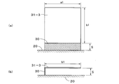
- FIGS. 63 (a) and 63 (b) has a horizontal length a1 of about 50 mm and a vertical length b1 of about 50 mm.
- FIG. 63 (a) shows that the top portion 31-3 has the top portion 31-3.
- FIG. 3 is a front view showing a configuration vertically arranged on an antenna substrate 30 standing on an antenna base 20, and the height of the antenna substrate 30 is a clearance S.
- FIG. 63B is a side view showing a configuration in which the top portion 31-3 is horizontally disposed on the antenna substrate 30 standing on the antenna base 20, and the height of the antenna substrate 30 is defined as a clearance S.
- FIG. 66 shows a change characteristic of the antenna capacity when the clearance S is changed from about 10 mm to about 50 mm in the first configuration shown in FIGS. 63 (a) and 63 (b). Referring to FIG. 66, when the top portion 31-3 is arranged vertically as shown in FIG.
- the maximum antenna capacity is about 2.8 pF when the clearance S is 10 mm, and the clearance S is When the clearance S is 40 mm, the antenna capacity is about 1.9 pF. Further, when the top portion 31-3 is disposed horizontally as shown in FIG. 63 (b), the area facing the antenna base 20 becomes large, and when the clearance S is 10 mm, the antenna capacity is about 4. When the clearance S is 40 mm, the antenna capacity is about 2 pF.
- FIGS. 64 (a) and 64 (b) has a horizontal length a2 of about 50 mm and a vertical length b2 of about 25 mm.
- FIG. 64 (a) shows the top portion 31.
- -3 is a front view showing a configuration in which the antenna substrate 30 is vertically arranged on the antenna substrate 30 standing on the antenna base 20, and the height of the antenna substrate 30 is defined as a clearance S.
- FIG. 64B is a side view showing a configuration in which the top portion 31-3 is horizontally disposed on the antenna substrate 30 erected on the antenna base 20, and the height of the antenna substrate 30 is defined as a clearance S. Yes.
- FIG. 67 shows a change characteristic of the antenna capacity when the clearance S is changed from about 10 mm to about 50 mm in the second configuration shown in FIGS. 64 (a) and 64 (b).
- the maximum antenna capacity is about 2.1 pF when the clearance S is 10 mm
- the clearance S is When the clearance S is 40 mm
- the antenna capacity is about 1.3 pF.
- the top portion 31-3 is horizontally arranged, the area facing the antenna base 20 is large, and when the clearance S is 10 mm, the maximum is about 3 pF.
- the antenna capacity decreases to about 1.4 pF when the clearance S is 40 mm.
- FIGS. 65 (a) and 65 (b) has a horizontal length a3 of about 50 mm and a vertical length b3 of about 3 mm.
- FIG. 65 (a) shows the top portion 31.
- -3 is a front view showing a configuration in which the antenna substrate 30 is vertically arranged on the antenna substrate 30 standing on the antenna base 20, and the height of the antenna substrate 30 is defined as a clearance S.
- FIG. 65B is a side view showing a configuration in which the top portion 31-3 is disposed horizontally on the antenna substrate 30 standing on the antenna base 20, and the height of the antenna substrate 30 is defined as a clearance S.
- FIG. 68 shows a change characteristic of the antenna capacity when the clearance S is changed from about 10 mm to about 50 mm in the third configuration shown in FIGS. 65 (a) and 65 (b).
- the top portion 31-3 when the top portion 31-3 is arranged vertically as shown in FIG. 65 (a), the maximum becomes the antenna capacity when the clearance S is 10 mm, and the clearance S becomes large.
- the antenna capacity becomes about 0.7 pF.
- FIG. 65 (b) the same applies when the top portion 31-3 is disposed horizontally, and the maximum is obtained when the clearance S is 10 mm, and the antenna capacity becomes about 1 pF.
- the antenna capacity becomes about 0.7 pF.
- the antenna capacity is the sum of the antenna overall capacity Ca and the reactive capacity Ci, and the reactive capacity Ci is a stray capacity generated by the facing area between the antenna element section 50 and the ground.
- the opposing area between the top portion 31-3 and the antenna base 20 is increased, and the reactive capacitance Ci is increased. Since the invalid capacity Ci decreases in inverse proportion to the clearance S, the antenna capacity decreases as the clearance S increases. In this case, the decreasing capacity is a capacity based on the reactive capacity Ci, and the overall antenna capacity Ca does not change even if the clearance S changes. Therefore, as shown in the change characteristics of the antenna capacity in FIGS. 66 to 68, it can be seen that the reactive capacity Ci is reduced by reducing the facing area between the top portion 31-3 and the antenna base 20.
- the reactive capacitance Ci decreases as the area of the top portion 31-3 is reduced. However, even if the area of the top portion 31-3 is increased, the reactive capacitance Ci can be reduced by being arranged vertically. . Then, in the top part 31 in the antenna apparatus 1 of the Example of this invention, it comprises the antenna base 20 by comprising the 1st side part 31a and the 2nd side part 31b which were made into the steep slope from the top to both sides. The reactive area is reduced by reducing the facing area.
- the antenna device 1 has a low posture and a height of about 70 mm or less.
- an antenna element is configured by the top portion 31 and the antenna pattern 30 b formed on the antenna substrate 30.
- the antenna capacity of the antenna element is about 4.7 pF.
- the height h10 from the lower edge of the top part 31 to the upper surface of the antenna base 20 is about 34.4 mm, and the dimension of the top part 31 is the above-described dimension.
- the antenna capacity in the antenna device 1 of the present invention is preferably about 3 pF or more so that the antenna element functions effectively as an antenna.
- the height h10 from the lower edge of the top portion 31 indicated by the clearance S to the upper surface of the antenna base 20 is preferably about 10 mm or more. Further, by moving the rear portion of the top portion 31 so as to protrude rearward from the rear end of the antenna base 20, the electrical characteristics can be improved. Furthermore, the shape of the top portion 31 is not limited to the shape shown in FIGS. 15 to 18, and may be the shape of the top portion 31-1 shown in FIGS. 40 to 43. In the above description, the top portion made of a metal plate is built in by attaching it to the antenna case. However, the top portion is deposited or adhered to the upper inner surface of the antenna case so that the top portion is placed in the antenna case. You may make it incorporate. Moreover, although the antenna device according to the present invention is mounted on a vehicle mounted on a roof or trunk of a vehicle, the present invention is not limited to this, and any antenna device that receives an AM wave band and an FM wave band can be applied.
Landscapes
- Engineering & Computer Science (AREA)
- Remote Sensing (AREA)
- Details Of Aerials (AREA)
- Support Of Aerials (AREA)
- Variable-Direction Aerials And Aerial Arrays (AREA)
Abstract
Description
また、アンテナ装置100において、エレメント110をアンテナ基部111に対して垂直方向に回動させてアンテナ基部111の下面からエレメント110の先端までの高さh101を約70mmとした状態を示す側面図を図71に示す。
これらの図に示す本発明の実施例にかかるアンテナ装置1は、車両のルーフに取り付けられるアンテナ装置とされており、車両に取り付けられた際に車両から突出する高さhは約70mmとされている。アンテナ装置1は極めて低姿勢(周波数100MHzの波長をλとすると、高さhは約0.0023λ以下)とされているが、AM放送とFM放送を受信することが可能とされている。このアンテナ装置1の形状は先端に行くほど細くなる流線型とされており、車両の美観・デザインを損ねないようある程度の範囲内において自由に形状を決定することができる。そして、アンテナ装置1の下面には、ゴム製またはエラストマー製の柔軟なベースパッドが嵌着されており、車両に水密に取り付けることができるようにされている。
図7を参照して本発明にかかるアンテナ装置1の組み立てについて説明すると、アンテナケース10内の上部にトップ部31が2本のネジ40により固着される。アンテナ基板30の上端には接続金具36が嵌着される。接続金具36はアンテナ基板30を挟持することによりアンテナ基板30の上部に取り付けられる。また、アンテナ基板30上にコイル35がハンダ付けされて取り付けられる。このアンテナ基板30は、2本のネジ41によりアンテナベース20に立設されて固着される。また、アンプ基板34はアンテナ基板30より前方に配置され、3本のネジ42によりアンテナベース20にほぼ平行に固着される。アンプ基板34からは増幅されたAM受信信号およびFM受信信号を出力するケーブル22が導出されており、ケーブル22の先端に端子43が装着され、端子43はアンプ基板34の裏面に固着される。また、アンテナ基板30に針金状の接続線33の一端が接続され、接続線33の他端がアンプ基板34に接続されることにより、アンテナ基板30に設けられたコイル35の出力端とアンプ基板34に設けられたAM/FMアンプの入力端とが接続されて、アンテナパターンとトップ部31とにより構成されるアンテナエレメントにより受信されたAM/FM受信信号がアンプ基板34におけるAM/FMアンプに入力されるようになる。アンテナベース20の引き出し孔から引き出されたケーブル22を束ねるように、ケーブル22の根本にはカラー45が嵌着される。
アンテナベース20の下面にはベースパッド24が嵌着される。ベースパッド24の周縁部には合計5つのネジの頭部が挿通可能な孔部が形成されており、この孔部に下から5本のネジ46を挿通して、ネジ46をアンテナベース20の周縁部に形成された嵌入孔に挿通し、アンテナケース10の下面の周縁に螺着する。これにより、アンテナ装置1を組み立てることができる。組み立てられたアンテナ装置1を、車両に形成された取付孔にボルト部21を位置合わせして取り付けると、上述したようにフック44によりアンテナ装置1は取付孔に仮止めされる。この状態において、車内からナット47をボルト部21に螺着することにより、アンテナ装置1を車体に取り付けることができる。
これらの図の説明は前述した通りであるから説明は省略するが、アンテナ基板30は2本のネジ41によりアンテナベース20に立設して取り付けられており、アンテナ基板30の下端には切欠30iが形成されて、この切欠30iに一部収納されるようGPSアンテナ32をアンテナベース20に取り付けることができる。GPSアンテナ32が取り付けられた場合は、GPSアンテナ32からもケーブル22に沿ってケーブルが導出される。また、アンテナ基板30の上部を跨ぐように配置されたトップ部31の斜面とされた側部の下縁とアンテナベース20の上面との間隔がh10とされ、間隔h10は例えば約34.4mmとされている。なお、GPSアンテナ32は必要とされる場合に限って取り付けられる。また、トップ部31の後部は斜めに切り取られてアンテナベース20の後端より後方へ突出されており、アンテナベース20との対向面積が極力低減されている。
これらの図に示すように、アンテナケース10は電波透過性の合成樹脂製とされており、先端に行くほど細くなる流線型の外形形状とされている。アンテナケース10内には、立設されたアンテナ基板30およびアンテナ基板30の上部に配置されたトップ部31を収納できる空間と、アンプ基板34を横方向に収納できる空間が形成されている。
これらの図に示すトップ部31は、金属板を加工して形成されており、前方に向かって緩やかに降下する曲面とされた頂部を有し、頂部から両側に傾斜した第1側部31aと第2側部31bが形成されている。第1側部31aと第2側部31bの斜面は急傾斜の斜面とされている。第1側部31aと第2側部31bには3つずつスリット31fが形成されて、それぞれの側部31a、31bは4つの片からなっている。この片の内のほぼ中央よりの一対の片が接触片31cとされている。接触片31cは、中途からほぼ垂直なるよう折曲されて形成されている。また、トップ部31の頂部には平坦部31eが2カ所形成されて、平坦部31eにそれぞれネジ孔31dが形成されている。このネジ孔31dにそれぞれネジ40が挿通されて、アンテナケース10の頂部の内側に螺着されることにより、トップ部31がアンテナケース10に内蔵されるようになる。
これらの図に示すフック44は、矩形状の本体部44aを有し、本体部44aの4隅から下方へ向かって、先端に鈎状の係合片が形成された嵌合脚部44bが一側の両側部に対向するように形成されている。また、他側の両側部のほぼ中央から下方へ延伸するように長い係合脚部44cが対向するように形成されている。フック44をアンテナベース20に取り付ける際には、嵌合脚部44bがアンテナベース20に形成された矩形穴の縁部に係合し、長い係合脚部44cはアンテナベース20に形成された矩形穴から抜け出てボルト部21の側面に沿って突出するようになる。係合脚部44cは、アンテナ装置1を車体に取り付ける際に、車体に設けられた取付孔の縁部に係合して、アンテナ装置1が抜け出ないように仮止めできるようになる。
これらの図に示すアンテナベース20は、前部がテーパ状に細くされたほぼ矩形状の平板からなる本体部20aを有し、本体部20aの周縁部には合計5つの嵌入孔20fが形成されている。この嵌入孔20fに下からそれぞれ挿通されたネジ46をアンテナケース10の下面の周辺部に螺着することにより、アンテナケース10がアンテナベース20に嵌着される。本体部20aのテーパ状に細くされた前部には3つのボス20eが形成されており、このボス20e上にアンプ基板34が載置されてアンプ基板34に挿通されたネジ42をそれぞれボス20eに螺着することにより、アンプ基板34をアンテナベース20に固着することができる。
これらの図に示すベースパッド24は、前部に向かって次第に細くなる曲面とされ、後端が直線状とされた細長い楕円形を半截した形状の平板からなる本体部24aを有し、本体部24aの表面にはアンテナベース20の外形形状に沿った形状の周壁部24bが形成されている。ベースパッド24の表面にアンテナベース20を載置して、周壁部24bにアンテナベース20の周縁を嵌合することにより、アンテナベース20の下面にベースパッド24が嵌着される。また、周壁部24bに沿って合計5つの孔部24dが形成されており、この孔部24dには、アンテナベース20の嵌入孔20fに下から挿通されるネジ46の頭部が挿通される。本体部24aの中央から前部にかけて楕円形の切欠孔24cが形成されており、この切欠孔24cからはアンテナベース20の下面に設けられているボルト部21とケーブル22およびカラー45が突出するようになる。
これらの図に示す接続金具36は弾性を有する金属板を加工して形成されており、中央部が折り返されるよう折曲されている金具本体36aを有している。金具本体36aにおける前部と後部の両側にはそれぞれ挟持片36cが形成されており、2枚ずつの挟持片36cが向き合って配置され、その先端部が接触していると共に先端が開くように加工されている。また、2組の挟持片36cの間には挟持片36cより長く形成された接触片36bが向き合って形成されている。接触片36bは下方へ行くほど拡がるように拡開され先端部は外方へ向かって半円形にカールされている。接続金具36は、アンテナ基板30の上端を挟持するように取り付けられる。この際に、一対の挟持片36cの先端が開いていることから、アンテナ基板30の上端から容易に挟持片36cの間に挿入することができるようになる。また、接続金具36がアンテナ基板30の上部に挿着された際に、アンテナ基板30の上部に形成されているアンテナパターンに接続金具36が電気的に接続されるようになる。また、アンテナベース20にアンテナケース10を嵌着した際に、アンテナケース10内に取り付けられているトップ部31の接触片31cの内面に拡開されている接触片36bが接触する。これにより、トップ部31は接続金具36を介してアンテナパターンに電気的に接続されるようになる。
これらの図に示すアンテナ基板30は、高周波特性の良好なガラスエポキシ基板等のプリント基板とされている基板本体30aを備え、基板本体30aには矩形状の部分の上部から突出する突出部30fと左下部から左側へ突出する部分が形成されている。基板本体30aの上部と突出部30fにはアンテナパターン30bが両面に形成されており、左側の周縁にはアンテナパターン30bの下から細長いパターンが左下部から突出する部分にかけて両面に形成されている。また、突出部30fは接続金具36を挿着する部位とされ、突出部30fの上端の両側には接続金具36の位置決めのための突起30hがそれぞれ形成されている。基板本体30aの下部には2つの取付孔30dが形成されており、取付孔30dの間に切欠30iが形成されている。この取付孔30dの周囲にはリング状のパターンが両面に形成されており、取付孔30dにそれぞれネジ41が挿通されてアンテナベース20のネジ部20dに螺着されることにより、アンテナ基板30がアンテナベース20に立設して取り付けられる。また、切欠30iに一部収納されるようGPSアンテナ32がアンテナベース20に取り付けられる。
図37に示すアンテナ装置1における平均利得の周波数帯域は76MHz~90MHzのFM波帯の周波数帯域とされており、従来のアンテナ装置100において全高h100を約195mm(図70参照)とした場合を従来例1として、全高h100を約70mm(図71参照)とした場合を従来例2として示している。従来例1と従来例2との平均利得の周波数特性を参照すると、全高h100を約195mmから約70mmに低くすると、FM波帯の周波数帯域の全体にわたり平均利得が約7dB劣化することが分かる。そして、図37を参照すると、本発明のアンテナ装置1は取り付けられた際に突出する高さhが約70mmとされていても全高h100が約195mmとされた従来例1と同等の平均利得の周波数特性が得られており、特に約84MHz以上の高域においては向上した平均利得が得られていることがわかる。
図38に示すS/N比の周波数帯域は531kHz~1602kHzのAM波帯の周波数帯域とされている。図38は従来例1のアンテナ装置100を基準として、従来例1のアンテナ装置100においてS/N比が20dB得られるアンテナ入力値を0dBに基準化し、本発明のアンテナ装置1および従来例2のアンテナ装置100において20dBのS/N比が得られるアンテナ入力値を、基準化されたアンテナ入力値に対する入力改善値[dB]として示している。従来例1と従来例2との入力改善値の周波数特性を参照すると、全高h100を約195mmから約70mmに低くすると、AM波帯の周波数帯域の全体にわたり入力改善値が約4.5~約5dB劣化することが分かる。すなわち、S/N比が劣化する。そして、図38を参照すると、本発明のアンテナ装置1は高さhが約70mmとされていても全高h100が約195mmとされた従来例1と同等以上の入力改善値の周波数特性が得られており、周波数が高くなるにつれて向上した入力改善値が得られて、S/N比が向上されていることがわかる。
図39に示す周波数帯域は76MHz~90MHzのFM波帯の周波数帯域とされている。図39においても従来例1のアンテナ装置100においてS/N比が30dB得られるアンテナ入力値を0dBに基準化し、本発明のアンテナ装置1および従来例2のアンテナ装置100において30dBのS/N比が得られるアンテナ入力値を、基準化されたアンテナ入力値に対する入力改善値[dB]として示している。従来例1と従来例2との入力改善値の周波数特性を参照すると、全高h100を約195mmから約70mmに低くすると、FM波帯の周波数帯域の低域(76MHz)においては約4dB劣化し、中域(83MHz)においては約1dBの劣化にとどまるが中域から高域に行くにつれて劣化するようになり90MHzでは7dB劣化することが分かる。そして、図39を参照すると、本発明のアンテナ装置1は高さhが約70mmとされていても全高h100が約195mmとされた従来例1と同等の入力改善値の周波数特性が得られて、S/N比が向上されていることがわかる。
図40は基礎実験に用いたアンテナ装置1の構成を示す平面図であり、図41は基礎実験に用いたアンテナ装置1の構成を示す正面図であり、図42は基礎実験に用いたアンテナ装置1の構成を示す右側面図である。これらの図に示すように、アンテナ装置1におけるトップ部31-1の形状は実施例のトップ部31と若干異なっているが長さや幅の寸法はほぼ同様とされており、アンテナエレメントとしてはほぼ同様の電気的性能を奏している。トップ部31-1は、頂部がほぼ平坦に形成されて両側部は下方へ向かって急傾斜の斜面とされている。トップ部31-1の後部は斜めに切り取られてアンテナベース20との対向面積を極力低減させている。このトップ部後方突出長さの基礎実験では、図40,図41に示すように標準の位置からのトップ部31-1の移動量LをL1,L2,L3,L4と後方へ移動しており、ここでは、移動量L1,L2,L3,L4をそれぞれ約10mm、約20mm、約30mm、約40mmとしている。なお、図43はトップ部31-1の移動量Lを約40mm(L4)とした際の構成を示す正面図とされている。
上記した基礎実験から、トップ部31を後方へ移動するほどグランドからの間隔が大きくなって、グランドとトップ部31間の浮遊容量が減少されて、AM波帯においてもFM波帯においてもゲインおよびS/N比が向上することが分かる。
図51は基礎実験に用いたアンテナ装置1の構成を示す右側面図であり、図52は基礎実験に用いたアンテナ装置1の構成を示す正面図であり、図53は基礎実験に用いたアンテナ装置1の構成を示す平面図である。これらの図に示すように、アンテナ装置1におけるトップ部31-2の形状は実施例のトップ部31と若干異なっており、前述したトップ部を後方へ移動させる基礎実験に用いたトップ部31-1の両側部の寸法を大きくした形状とされている。下方へ向かって急傾斜の斜面とされているトップ部31-2の両側部は、水平方向に約50mmとされ斜面における下方への寸法が約60mmとされている。このトップ部高さの基礎実験では、図51ないし図53に示すようにトップ部31-2のアンテナベース20からの高さHをH1,H2,H3,H4と高くしており、ここでは、高さH1,H2,H3,H4をそれぞれ約5mm、約10mm、約20mm、約30mmとしている。なお、図54はトップ部31-2の高さHを約30mm(H4)とした際の構成を示す正面図であり、図55はトップ部31-2の高さHを約30mm(H4)とした際の構成を示す右側面図とされている。
上記した基礎実験から、トップ部31のアンテナベース20からの高さHを高くするほどアンテナベース20とされるグランドからの間隔が大きくなって、グランドとトップ部31間の浮遊容量が減少されるようになる。ここでは、高さHを約10mm以上とするとAM波帯においてもFM波帯においてもゲインおよびS/N比が向上することが分かる。
Vi=V0・Ca/(Ca+Ci) (1)
(1)式で示されるように、無効容量Ciが小さいほどアンプAMPに入力されるアンテナ入力部電圧Viは大きくなって、アンテナ装置1のゲインが向上することがわかる。
上記の説明では金属板からなるトップ部をアンテナケース内に取り付けることにより内蔵するようにしたが、トップ部をアンテナケース内の上部内面に蒸着あるいは貼着することにより、トップ部をアンテナケース内に内蔵させるようにしてもよい。また、本発明にかかるアンテナ装置は車両のルーフやトランクに取り付けられる車載用としたが、これに限るものではなくAM波帯とFM波帯を受信するアンテナ装置であれば適用することができる。
Claims (3)
- アンテナケースと、該アンテナケース内に収納されるアンテナ部とを備え、取り付けられた際に約70mm以下の高さで突出するアンテナ装置であって、
前記アンテナ部は、
前記アンテナケースの下端に、前記アンテナケースの下面を閉塞するよう嵌着される導電性のアンテナベースと、
該アンテナベース上に立設されて配置され、アンテナパターンが上部に形成されているアンテナ基板と、
頂部と、該頂部の両側から斜面とされた側部が形成されて断面形状が山形に形成されており、前記アンテナ基板を跨ぐように配置されていると共に、前記頂部近傍が前記アンテナパターンに接続されて、前記アンテナパターンと共にアンテナエレメントを構成している導電性のトップ部と、
前記アンテナエレメントにより受信されたAM放送とFM放送の信号を増幅するアンプが設けられ、前記アンテナベース上に配置されているアンプ基板とを備え、
前記トップ部における前記側部の下縁と前記アンテナベースとの間隔が約10mm以上とされていると共に、前記トップ部の大きさが、前記アンテナエレメントのアンテナ容量が約3pF以上となる大きさとされており、前記アンテナ基板における前記アンテナパターンが、前記アンプ基板における前記アンプの入力に、前記アンテナエレメントのインダクタンス分を補うコイルを介して接続されていることを特徴とするアンテナ装置。 - 前記アンテナパターンが形成されている前記アンテナ基板の上部を挟持するように取り付けられ、両側に拡がるよう形成されている接触片を有する接続金具を、前記アンテナ部はさらに備え、
前記アンテナケース内の上部に前記トップ部が内蔵されて取り付けられており、前記アンテナケースにより前記アンテナ部を覆うように前記アンテナベースに前記アンテナケースを取り付けた際に、前記接続金具の前記接触片が前記トップ部の前記側部の内側に接触することにより、前記トップ部と前記アンテナパターンとが電気的に接続されることを特徴とする請求項1記載のアンテナ装置。 - 前記トップ部の後部が、前記アンテナベースの後端より後方に突出していることを特徴とする請求項1記載のアンテナ装置。
Priority Applications (6)
| Application Number | Priority Date | Filing Date | Title |
|---|---|---|---|
| BRPI0908167-4A BRPI0908167B1 (pt) | 2008-07-11 | 2009-03-19 | aparelho de antena |
| US12/735,199 US8497807B2 (en) | 2008-07-11 | 2009-03-19 | Antenna apparatus |
| CN2009801042530A CN101939876A (zh) | 2008-07-11 | 2009-03-19 | 天线装置 |
| EP09794119.9A EP2312692A4 (en) | 2008-07-11 | 2009-03-19 | ANTENNA DEVICE |
| US13/603,775 US8502742B2 (en) | 2008-07-11 | 2012-09-05 | Antenna apparatus |
| US13/774,107 US8842052B2 (en) | 2008-07-11 | 2013-02-22 | Antenna apparatus |
Applications Claiming Priority (2)
| Application Number | Priority Date | Filing Date | Title |
|---|---|---|---|
| JP2008181545A JP2010021856A (ja) | 2008-07-11 | 2008-07-11 | アンテナ装置 |
| JP2008-181545 | 2008-07-11 |
Related Child Applications (2)
| Application Number | Title | Priority Date | Filing Date |
|---|---|---|---|
| US12/735,199 A-371-Of-International US8497807B2 (en) | 2008-07-11 | 2009-03-19 | Antenna apparatus |
| US13/603,775 Continuation US8502742B2 (en) | 2008-07-11 | 2012-09-05 | Antenna apparatus |
Publications (1)
| Publication Number | Publication Date |
|---|---|
| WO2010004671A1 true WO2010004671A1 (ja) | 2010-01-14 |
Family
ID=41506799
Family Applications (1)
| Application Number | Title | Priority Date | Filing Date |
|---|---|---|---|
| PCT/JP2009/001231 WO2010004671A1 (ja) | 2008-07-11 | 2009-03-19 | アンテナ装置 |
Country Status (7)
| Country | Link |
|---|---|
| US (3) | US8497807B2 (ja) |
| EP (1) | EP2312692A4 (ja) |
| JP (1) | JP2010021856A (ja) |
| KR (1) | KR20110031903A (ja) |
| CN (2) | CN103094670B (ja) |
| BR (1) | BRPI0908167B1 (ja) |
| WO (1) | WO2010004671A1 (ja) |
Cited By (8)
| Publication number | Priority date | Publication date | Assignee | Title |
|---|---|---|---|---|
| JP2011199440A (ja) * | 2010-03-18 | 2011-10-06 | Mitsumi Electric Co Ltd | アンテナ装置 |
| CN102427170A (zh) * | 2010-07-30 | 2012-04-25 | 株式会社友华 | 天线设备 |
| JP2014049993A (ja) * | 2012-08-31 | 2014-03-17 | Kojima Press Industry Co Ltd | アンテナ装置 |
| CN104868227A (zh) * | 2015-04-03 | 2015-08-26 | 卜放 | 组合天线振子、矮型车载天线及制造组合天线振子的方法 |
| USD803196S1 (en) | 2015-09-25 | 2017-11-21 | Taoglas Group Holdings Limited | Dual fin antenna |
| CN110943277A (zh) * | 2014-02-10 | 2020-03-31 | 株式会社友华 | 天线装置 |
| WO2022102771A1 (ja) * | 2020-11-16 | 2022-05-19 | 株式会社ヨコオ | アンテナ |
| WO2022209793A1 (ja) * | 2021-03-29 | 2022-10-06 | 株式会社ヨコオ | 車載用アンテナ装置 |
Families Citing this family (59)
| Publication number | Priority date | Publication date | Assignee | Title |
|---|---|---|---|---|
| GB2468612B (en) | 2007-12-20 | 2012-05-23 | Harada Ind Co Ltd | Patch antenna device |
| JP4524318B2 (ja) | 2008-05-27 | 2010-08-18 | 原田工業株式会社 | 車載用ノイズフィルタ |
| JP5114325B2 (ja) | 2008-07-08 | 2013-01-09 | 原田工業株式会社 | 車両用ルーフマウントアンテナ装置 |
| JP4832549B2 (ja) * | 2009-04-30 | 2011-12-07 | 原田工業株式会社 | 空間充填曲線を用いる車両用アンテナ装置 |
| JP4955094B2 (ja) * | 2009-11-02 | 2012-06-20 | 原田工業株式会社 | パッチアンテナ |
| WO2012096355A1 (ja) * | 2011-01-12 | 2012-07-19 | 原田工業株式会社 | アンテナ装置 |
| KR101192298B1 (ko) * | 2011-01-25 | 2012-10-17 | 인팩일렉스 주식회사 | 샤크핀 통합형 안테나 |
| JP5274597B2 (ja) | 2011-02-15 | 2013-08-28 | 原田工業株式会社 | 車両用ポールアンテナ |
| JP5654914B2 (ja) * | 2011-03-23 | 2015-01-14 | 原田工業株式会社 | アンテナ装置 |
| JP5654917B2 (ja) | 2011-03-24 | 2015-01-14 | 原田工業株式会社 | アンテナ装置 |
| CN104752814B (zh) * | 2012-01-30 | 2017-04-12 | 原田工业株式会社 | 天线装置 |
| CN103730713B (zh) * | 2012-01-30 | 2017-03-01 | 原田工业株式会社 | 天线装置 |
| CN103730726B (zh) * | 2012-01-30 | 2017-04-12 | 原田工业株式会社 | 天线装置 |
| CN103378409B (zh) * | 2012-04-20 | 2016-03-16 | 卜放 | 伞型天线振子及天线系统 |
| JP5986634B2 (ja) * | 2012-06-26 | 2016-09-06 | 原田工業株式会社 | 低背型アンテナ装置 |
| JP5920122B2 (ja) * | 2012-09-03 | 2016-05-18 | 株式会社デンソー | 車載用アンテナ装置 |
| JP5920123B2 (ja) | 2012-09-03 | 2016-05-18 | 株式会社日本自動車部品総合研究所 | 車載用アンテナ装置 |
| USD726696S1 (en) | 2012-09-12 | 2015-04-14 | Harada Industry Co., Ltd. | Vehicle antenna |
| CN103682553B (zh) * | 2012-09-21 | 2015-10-21 | 卜放 | 具有伞形振子的汽车天线 |
| US9595752B2 (en) * | 2012-11-02 | 2017-03-14 | Harada Industry Co., Ltd. | Vehicle antenna unit |
| DE102013005001A1 (de) * | 2013-03-24 | 2014-09-25 | Heinz Lindenmeier | Breitband-Monopolantenne für zwei durch eine Frequenzlücke getrennte Frequenzbänder im Dezimeterwellenbereich für Fahrzeuge |
| CN103236590B (zh) * | 2013-04-07 | 2015-12-23 | 上海原田新汽车天线有限公司 | 天线装置 |
| EP2806497B1 (en) * | 2013-05-23 | 2015-12-30 | Nxp B.V. | Vehicle antenna |
| JP5655126B2 (ja) * | 2013-10-18 | 2015-01-14 | 原田工業株式会社 | アンテナ装置 |
| JP5592989B2 (ja) * | 2013-10-18 | 2014-09-17 | 原田工業株式会社 | アンテナ装置 |
| JP5931937B2 (ja) * | 2014-02-04 | 2016-06-08 | 原田工業株式会社 | パッチアンテナ装置 |
| KR20150098343A (ko) * | 2014-02-20 | 2015-08-28 | 현대자동차주식회사 | 대역폭이 확장된 차량용 이중 대역 pcb 안테나 장치 |
| JP6206243B2 (ja) * | 2014-02-21 | 2017-10-04 | 株式会社Soken | 集合アンテナ装置 |
| JP6437232B2 (ja) * | 2014-07-28 | 2018-12-12 | 株式会社ヨコオ | 車載用アンテナ装置 |
| JP5989722B2 (ja) * | 2014-08-04 | 2016-09-07 | 原田工業株式会社 | アンテナ装置 |
| JP5674988B2 (ja) * | 2014-09-19 | 2015-02-25 | 原田工業株式会社 | アンテナ装置 |
| JP5918844B2 (ja) * | 2014-12-22 | 2016-05-18 | 原田工業株式会社 | アンテナ装置 |
| WO2017046971A1 (ja) * | 2015-09-14 | 2017-03-23 | 株式会社ヨコオ | アンテナ装置 |
| JP6236515B2 (ja) * | 2015-11-27 | 2017-11-22 | 原田工業株式会社 | 低背型アンテナ装置 |
| US11456524B2 (en) * | 2016-02-19 | 2022-09-27 | Yokowo Co., Ltd. | Antenna device |
| JP5956096B1 (ja) * | 2016-04-08 | 2016-07-20 | 原田工業株式会社 | アンテナ装置 |
| JP2018006918A (ja) * | 2016-06-29 | 2018-01-11 | 株式会社フジクラ | アンテナ装置 |
| CN106252892B (zh) * | 2016-09-21 | 2023-06-13 | 赫思曼汽车通讯设备(上海)有限公司 | 一种天线装置 |
| CN114530698A (zh) | 2016-12-06 | 2022-05-24 | 株式会社友华 | 天线装置 |
| JP1578053S (ja) * | 2017-01-31 | 2017-06-05 | ||
| WO2018155600A1 (ja) | 2017-02-23 | 2018-08-30 | 株式会社ヨコオ | アンテナ装置 |
| JP6877178B2 (ja) * | 2017-02-23 | 2021-05-26 | 株式会社ヨコオ | アンテナ装置 |
| US11804653B2 (en) | 2017-02-23 | 2023-10-31 | Yokowo Co., Ltd. | Antenna device having a capacitive loading element |
| US11251528B2 (en) | 2017-02-28 | 2022-02-15 | Yokowo Co., Ltd. | Antenna device |
| JP7224716B2 (ja) * | 2017-03-29 | 2023-02-20 | 株式会社ヨコオ | アンテナ装置 |
| JP6992052B2 (ja) * | 2017-03-31 | 2022-01-13 | 株式会社ヨコオ | アンテナ装置 |
| CN108808218B (zh) * | 2017-04-28 | 2021-11-02 | 原田工业株式会社 | 天线装置 |
| JP6918607B2 (ja) * | 2017-06-30 | 2021-08-11 | 株式会社ヨコオ | アンテナ装置 |
| DE102017211386B4 (de) * | 2017-07-04 | 2021-01-07 | Continental Automotive Gmbh | Federkontakt zum Verbinden von einer Antenne mit einer gedruckten Schaltung |
| JP6991759B2 (ja) * | 2017-07-07 | 2022-01-13 | 株式会社ヨコオ | アンテナ装置 |
| CN108390142A (zh) * | 2018-02-02 | 2018-08-10 | 莱尔德无线技术(上海)有限公司 | 天线组件 |
| CN108390141A (zh) * | 2018-02-02 | 2018-08-10 | 莱尔德无线技术(上海)有限公司 | 天线组件 |
| JP6956650B2 (ja) * | 2018-02-19 | 2021-11-02 | 株式会社ヨコオ | 車載用アンテナ装置 |
| CN108832314B (zh) * | 2018-06-05 | 2020-06-05 | 浙江大学 | 一种新型低剖面高增益车载天线 |
| TWI678842B (zh) * | 2018-09-03 | 2019-12-01 | 宏碁股份有限公司 | 行動裝置 |
| US11962076B2 (en) | 2018-09-14 | 2024-04-16 | Harada Industry Co., Ltd. | Antenna device |
| JP2022130755A (ja) * | 2019-07-24 | 2022-09-07 | 株式会社ヨコオ | 車載用アンテナ装置 |
| KR102192766B1 (ko) | 2019-08-19 | 2020-12-18 | 인팩일렉스 주식회사 | 차량용 샤크핀 안테나 |
| IT202100028934A1 (it) * | 2021-11-15 | 2023-05-15 | Ask Ind Spa | Antenna per autoveicoli |
Citations (6)
| Publication number | Priority date | Publication date | Assignee | Title |
|---|---|---|---|---|
| JP2000077923A (ja) * | 1998-09-01 | 2000-03-14 | Nippon Antenna Co Ltd | 車載用アンテナ |
| JP2003188619A (ja) | 2001-12-18 | 2003-07-04 | Yokowo Co Ltd | 車載用アンテナ |
| JP2003229715A (ja) * | 2002-02-04 | 2003-08-15 | Alps Electric Co Ltd | 車載用パッチアンテナ装置 |
| JP2004015096A (ja) * | 2002-06-03 | 2004-01-15 | Mitsumi Electric Co Ltd | 複合アンテナ装置 |
| JP2005072926A (ja) * | 2003-08-25 | 2005-03-17 | Kojima Press Co Ltd | 車両用アンテナ |
| JP2005223957A (ja) | 2005-04-28 | 2005-08-18 | Harada Ind Co Ltd | 車両用可倒式アンテナ |
Family Cites Families (7)
| Publication number | Priority date | Publication date | Assignee | Title |
|---|---|---|---|---|
| JPH08222924A (ja) * | 1995-02-20 | 1996-08-30 | Yazaki Corp | アンテナ構造 |
| JP3654340B2 (ja) * | 2000-09-08 | 2005-06-02 | 日本アンテナ株式会社 | 2周波用アンテナ |
| AU2002225461B2 (en) * | 2001-02-26 | 2005-12-15 | Nippon Antena Kabushiki Kaisha | Multifrequency antenna |
| JP4656317B2 (ja) | 2006-01-24 | 2011-03-23 | ミツミ電機株式会社 | アンテナ装置 |
| KR100808811B1 (ko) * | 2006-04-13 | 2008-03-03 | (주)모토닉스 | 차량용 다중대역 안테나 |
| US20080117111A1 (en) * | 2006-11-22 | 2008-05-22 | Nippon Antena Kabushiki Kaisha | Antenna Apparatus |
| US7492318B2 (en) | 2007-02-15 | 2009-02-17 | Laird Technologies, Inc. | Mobile wideband antennas |
-
2008
- 2008-07-11 JP JP2008181545A patent/JP2010021856A/ja active Pending
-
2009
- 2009-03-19 CN CN201310042794.3A patent/CN103094670B/zh active Active
- 2009-03-19 EP EP09794119.9A patent/EP2312692A4/en not_active Withdrawn
- 2009-03-19 WO PCT/JP2009/001231 patent/WO2010004671A1/ja active Application Filing
- 2009-03-19 CN CN2009801042530A patent/CN101939876A/zh active Pending
- 2009-03-19 BR BRPI0908167-4A patent/BRPI0908167B1/pt active IP Right Grant
- 2009-03-19 KR KR1020107025643A patent/KR20110031903A/ko not_active Application Discontinuation
- 2009-03-19 US US12/735,199 patent/US8497807B2/en active Active
-
2012
- 2012-09-05 US US13/603,775 patent/US8502742B2/en active Active
-
2013
- 2013-02-22 US US13/774,107 patent/US8842052B2/en active Active
Patent Citations (6)
| Publication number | Priority date | Publication date | Assignee | Title |
|---|---|---|---|---|
| JP2000077923A (ja) * | 1998-09-01 | 2000-03-14 | Nippon Antenna Co Ltd | 車載用アンテナ |
| JP2003188619A (ja) | 2001-12-18 | 2003-07-04 | Yokowo Co Ltd | 車載用アンテナ |
| JP2003229715A (ja) * | 2002-02-04 | 2003-08-15 | Alps Electric Co Ltd | 車載用パッチアンテナ装置 |
| JP2004015096A (ja) * | 2002-06-03 | 2004-01-15 | Mitsumi Electric Co Ltd | 複合アンテナ装置 |
| JP2005072926A (ja) * | 2003-08-25 | 2005-03-17 | Kojima Press Co Ltd | 車両用アンテナ |
| JP2005223957A (ja) | 2005-04-28 | 2005-08-18 | Harada Ind Co Ltd | 車両用可倒式アンテナ |
Non-Patent Citations (1)
| Title |
|---|
| See also references of EP2312692A4 |
Cited By (11)
| Publication number | Priority date | Publication date | Assignee | Title |
|---|---|---|---|---|
| JP2011199440A (ja) * | 2010-03-18 | 2011-10-06 | Mitsumi Electric Co Ltd | アンテナ装置 |
| CN102427170A (zh) * | 2010-07-30 | 2012-04-25 | 株式会社友华 | 天线设备 |
| CN102427170B (zh) * | 2010-07-30 | 2016-05-18 | 株式会社友华 | 天线设备 |
| JP2014049993A (ja) * | 2012-08-31 | 2014-03-17 | Kojima Press Industry Co Ltd | アンテナ装置 |
| US9666936B2 (en) | 2012-08-31 | 2017-05-30 | Kojima Industries Corporation | Antenna device |
| CN110943277A (zh) * | 2014-02-10 | 2020-03-31 | 株式会社友华 | 天线装置 |
| CN110943277B (zh) * | 2014-02-10 | 2021-10-22 | 株式会社友华 | 天线装置 |
| CN104868227A (zh) * | 2015-04-03 | 2015-08-26 | 卜放 | 组合天线振子、矮型车载天线及制造组合天线振子的方法 |
| USD803196S1 (en) | 2015-09-25 | 2017-11-21 | Taoglas Group Holdings Limited | Dual fin antenna |
| WO2022102771A1 (ja) * | 2020-11-16 | 2022-05-19 | 株式会社ヨコオ | アンテナ |
| WO2022209793A1 (ja) * | 2021-03-29 | 2022-10-06 | 株式会社ヨコオ | 車載用アンテナ装置 |
Also Published As
| Publication number | Publication date |
|---|---|
| EP2312692A1 (en) | 2011-04-20 |
| CN103094670B (zh) | 2015-10-28 |
| KR20110031903A (ko) | 2011-03-29 |
| US20120326934A1 (en) | 2012-12-27 |
| US8502742B2 (en) | 2013-08-06 |
| US8497807B2 (en) | 2013-07-30 |
| CN101939876A (zh) | 2011-01-05 |
| US8842052B2 (en) | 2014-09-23 |
| BRPI0908167B1 (pt) | 2021-05-11 |
| US20100265147A1 (en) | 2010-10-21 |
| CN103094670A (zh) | 2013-05-08 |
| EP2312692A4 (en) | 2014-05-14 |
| BRPI0908167A2 (pt) | 2015-12-15 |
| US20130176180A1 (en) | 2013-07-11 |
| JP2010021856A (ja) | 2010-01-28 |
Similar Documents
| Publication | Publication Date | Title |
|---|---|---|
| WO2010004671A1 (ja) | アンテナ装置 | |
| JP5007480B2 (ja) | アンテナ装置 | |
| CA2831022C (en) | Low-profile vehicle antenna | |
| EP0989629A1 (en) | Vehicular antenna | |
| US20080117111A1 (en) | Antenna Apparatus | |
| US20120081256A1 (en) | Antenna apparatus | |
| CA2677876A1 (en) | Antenna apparatus | |
| JP5918844B2 (ja) | アンテナ装置 | |
| JP2006270717A (ja) | 車載用アンテナ | |
| JP5956096B1 (ja) | アンテナ装置 | |
| JP5655126B2 (ja) | アンテナ装置 | |
| JP5592989B2 (ja) | アンテナ装置 | |
| JP5674988B2 (ja) | アンテナ装置 |
Legal Events
| Date | Code | Title | Description |
|---|---|---|---|
| WWE | Wipo information: entry into national phase |
Ref document number: 200980104253.0 Country of ref document: CN |
|
| 121 | Ep: the epo has been informed by wipo that ep was designated in this application |
Ref document number: 09794119 Country of ref document: EP Kind code of ref document: A1 |
|
| WWE | Wipo information: entry into national phase |
Ref document number: 12735199 Country of ref document: US |
|
| WWE | Wipo information: entry into national phase |
Ref document number: 2009794119 Country of ref document: EP |
|
| ENP | Entry into the national phase |
Ref document number: 20107025643 Country of ref document: KR Kind code of ref document: A |
|
| NENP | Non-entry into the national phase |
Ref country code: DE |
|
| ENP | Entry into the national phase |
Ref document number: PI0908167 Country of ref document: BR Kind code of ref document: A2 Effective date: 20100831 |