WO2010004615A1 - 車輌運搬車 - Google Patents
車輌運搬車 Download PDFInfo
- Publication number
- WO2010004615A1 WO2010004615A1 PCT/JP2008/062310 JP2008062310W WO2010004615A1 WO 2010004615 A1 WO2010004615 A1 WO 2010004615A1 JP 2008062310 W JP2008062310 W JP 2008062310W WO 2010004615 A1 WO2010004615 A1 WO 2010004615A1
- Authority
- WO
- WIPO (PCT)
- Prior art keywords
- frame
- loading platform
- vehicle
- roller
- rear end
- Prior art date
- Legal status (The legal status is an assumption and is not a legal conclusion. Google has not performed a legal analysis and makes no representation as to the accuracy of the status listed.)
- Ceased
Links
Images






Classifications
-
- B—PERFORMING OPERATIONS; TRANSPORTING
- B60—VEHICLES IN GENERAL
- B60P—VEHICLES ADAPTED FOR LOAD TRANSPORTATION OR TO TRANSPORT, TO CARRY, OR TO COMPRISE SPECIAL LOADS OR OBJECTS
- B60P3/00—Vehicles adapted to transport, to carry or to comprise special loads or objects
- B60P3/06—Vehicles adapted to transport, to carry or to comprise special loads or objects for carrying vehicles
- B60P3/07—Vehicles adapted to transport, to carry or to comprise special loads or objects for carrying vehicles for carrying road vehicles
-
- B—PERFORMING OPERATIONS; TRANSPORTING
- B60—VEHICLES IN GENERAL
- B60P—VEHICLES ADAPTED FOR LOAD TRANSPORTATION OR TO TRANSPORT, TO CARRY, OR TO COMPRISE SPECIAL LOADS OR OBJECTS
- B60P3/00—Vehicles adapted to transport, to carry or to comprise special loads or objects
- B60P3/12—Vehicles adapted to transport, to carry or to comprise special loads or objects for salvaging damaged vehicles
- B60P3/122—Vehicles adapted to transport, to carry or to comprise special loads or objects for salvaging damaged vehicles by supporting the whole vehicle
Definitions
- the present invention relates to a vehicle transport vehicle in which a load carrier is moved backward and tilted backward so that a transported vehicle can be loaded on the load carrier.
- a vehicle transporter it can also be applied to transporting agricultural machines, small ships (boats), heavy machinery, etc. in addition to vehicles as transport objects.
- This type of vehicle transport vehicle is configured such that the carrier is moved backward with respect to the inclined frame and the carrier is tilted backward together with the inclined frame so that the transported vehicle can be loaded on the carrier.
- two types of telescopic cylinders are used: a tilt cylinder that tilts an inclined frame and a slide cylinder that moves a cargo bed back and forth. In this way, using two types of telescopic cylinders increases the number of parts and increases costs, and since there are two drive systems, it is necessary to operate both drive systems (both telescopic cylinders) when using the cargo bed. The operation was troublesome.
- FIG.12 and FIG.13 the vehicle transport vehicle of patent 2532158 (patent document 1) is shown.
- an inclined frame 103 is pivotally supported at a rear end portion of a subframe 112 mounted on a chassis frame of the vehicle, while a loading platform 104 is movable back and forth on the inclined frame 103. It is installed in.
- the tilt frame 103 and the back and forth movement of the loading platform 104 can be simultaneously performed by a single telescopic cylinder 151 (FIG. 13).
- the inclined frame 103 includes an outer member 131 and an inner member 132 that are slidable with respect to each other. It is pivotally supported.
- a link mechanism 109 including first to third links 191, 192, and 193 is provided between the distal end portion of the inner member 132 of the inclined frame 103 and the sub frame 112.
- the links 191, 192, and 193 of the link mechanism 109 are relatively short for the second link 192 and relatively small for the third link 193. Long ones are used.
- Each of the first to third links 191, 192, 193 is assembled as shown in FIG. 13, and has a rather complicated configuration. That is, the first link 191 (with a guide groove) is configured such that the rear end portion thereof is pivotally supported on the subframe 112 by the hinge shaft 194 and can swing up and down.
- the proximal end of the second link 192 is pivotally supported by the hinge shaft 195 at the front end of the first link 191, and the distal end of the second link 192 and the distal end of the third link 193 are pivotally supported by the hinge shaft 196. ing.
- a roller 197 that fits into the guide groove of the first link 191 is attached to the base end portion of the third link 193, and the base end side of the third link 193 moves along the guide groove of the first link 191. It has come to be able to do.
- the second link 192 and the third link 193 of the link mechanism 109 are inclined to the front side.
- a groove-shaped bearing portion 198 (FIG. 13) is provided at the tip of the second link 192, and a shaft 133 provided at the tip of the inclined frame 103 (inner member 132) is provided on the bearing 198. It is designed to be engaged and disengaged.
- the second link 192 In the loading platform retracted state shown in FIG. 12 (A), the second link 192 is tilted forward, but in this posture, the bearing portion 198 is located considerably rearward of the shaft 133 (FIG. 13) at the tip of the inclined frame. Waiting in a forward-open state.
- the tilt frame 103 and the back and forth movement of the loading platform 104 can be simultaneously performed by one telescopic cylinder 151.
- the drive system can be shared, the structure of the link mechanism 109 (using the first to third three links) for tilting the tilt frame 103 is complicated and has a considerable weight, and the tilt frame Since 103 needs to be extendable, the structure of the inclined frame 103 is also complicated.
- the known vehicle carrier shown in FIGS. 12 and 13 has a problem that the number of parts is large, the assemblability is poor, the cost is increased as a whole, and the weight of the link mechanism 109 is increased. .
- the link mechanism 109 is used as the tilting support mechanism of the tilt frame 103 as in the vehicle carrier of this known example, the state shown in FIG.
- the second link 192 swings around the hinge shaft 195 (FIG. 13) until the state of 12 (B), and each link maintains a triangle from the state of FIG. 12 (B) to the state of FIG. 12 (C). As it is, it swings around the hinge shaft 194 (the link mechanism 109 swings in two steps).
- the tilting speed of the tilt frame 103 per the amount of expansion / contraction of the telescopic cylinder 151 changes in the initial standing stage, the standing intermediate stage, and the final standing stage of the link mechanism 109,
- the frame 103 is not tilted smoothly (at a constant speed).
- the tilting speed near the retracted posture horizontal posture
- a shock occurs in the tilted frame 103 at the end of the tilting.
- the link mechanism 109 is used as the tilting support mechanism of the tilt frame 103, a large cylinder output is required at the initial stage of the link mechanism 109. Therefore, the telescopic cylinder 151 has a large output corresponding to it (expensive). ) Must be used.
- the present invention provides a vehicle transport vehicle in which the tilt frame can be tilted and the loading platform can be moved back and forth at the same time with a single telescopic cylinder. Is intended to be able to tilt smoothly.
- the present invention has the following configuration as means for solving the above problems. Note that the present invention is directed to a vehicle transporter that allows a vehicle to be loaded on the carrier by moving the carrier backward and backward.
- the vehicle transport vehicle includes a vehicle having a chassis frame, an inclined frame supported to be tiltable at the rear end position of the chassis frame, and supported on the inclined frame so as to be movable in the longitudinal direction of the vehicle.
- a tilting platform provided between the tilting frame and the tilting frame and having a telescopic cylinder for moving the loading platform in the longitudinal direction of the vehicle with respect to the tilting frame, and tilting the tilting frame by the telescopic movement of the telescopic cylinder Device.
- a pair of left and right subframes can be installed on the chassis frame, but those without a subframe can also be employed.
- a frame having a subframe is expressed as a chassis frame including the subframe.
- the sloping frame is long and has a pair of left and right.
- the inclined frame is supported so as to be tiltable at the rear end position of the chassis frame (or sub-frame).
- the support portion may be a frame in which the inclined frame is pivotally supported.
- the chassis frame (or subframe) may be supported by a roller at the rear end position so that the inclined frame can be moved back and forth.
- another telescopic cylinder for moving the tilt frame back and forth may be provided.
- a grounding roller that rolls on the ground may be provided on the lower surface of the rear end of the loading platform.
- the board boarding board can be attached to the rear-end part of a loading platform so that raising / lowering is possible.
- the tilting device for tilting the tilting frame includes a guide rail attached to the chassis frame, an extension cylinder, and a roller attached to the tube of the extension cylinder and moving along the guide rail.
- the guide rail has a pair of left and right.
- the guide rail may be directly fixed to the chassis frame. However, if the subframe (a pair of left and right) is installed on the chassis frame, the guide rail can be attached to the subframe.
- the shape of the guide rail (roller guide rail described later) is set so that the tilting frame can be smoothly tilted (at substantially constant speed) during the expansion / contraction operation of the telescopic cylinder.
- the extension cylinder has a fairly long stroke. Note that only one telescopic cylinder is required. This telescopic cylinder is attached so that the cylinder rod is connected to the front portion of the inclined frame and the cylinder tube can be moved along the inclined frame in the vehicle longitudinal direction. The cylinder tube moves in the vehicle front-rear direction while maintaining a parallel posture in a side view with respect to the inclined frame.
- a roller that moves along the guide rail is attached to the tube of the telescopic cylinder, and the inclined frame can be gradually inclined backward by moving the roller to the rear side of the guide rail. That is, the inclined frame is supported so as to be tiltable at the rear end position of the chassis frame (or subframe), and the cylinder tube moves back and forth while maintaining a parallel posture with respect to the inclined frame in a side view. Therefore, when the telescopic cylinder is extended, the roller attached to the cylinder tube moves backward along the guide rail, whereby the inclined frame can be tilted backward through the cylinder tube.
- a double speed device is provided between the inclined frame and the loading platform so that the loading platform can be moved back and forth by an amount twice that of the expansion and contraction of the telescopic cylinder.
- This double speed device is used because the amount of forward / backward movement of the cargo bed cannot be sufficiently secured only by the expansion / contraction stroke of the expansion / contraction cylinder.
- this double speed device can employ a chain, a wire or the like wound around a pulley.
- the tilting device performs the backward tilting operation of the tilting frame and the backward movement of the loading platform simultaneously to lower the loading platform to a substantially horizontal position near the ground.
- the loading platform is installed so as to be tiltable with respect to the tilting frame around one point at the front end of the loading platform. Then, after the rear end portion of the loading platform is grounded by extending the telescopic cylinder, the tilt angle of the loading platform can be gradually reduced by further extending the expansion cylinder.
- the vehicle carrier according to claim 1 of the present application functions as follows. First, in the loading platform retracted state, the telescopic cylinder is contracted to the minimum and the roller attached to the telescopic cylinder is positioned near the front end of the guide rail, and the inclined frame is supported in a horizontal posture on the chassis frame. In this loading platform storage state, the loading platform is also supported in a horizontal posture at a position near the front of the vehicle.
- the telescopic cylinder is extended. Then, as the tube of the telescopic cylinder moves backward along the inclined frame, the roller attached to the cylinder tube moves backward along the guide rail, thereby tilting the inclined frame backward via the cylinder tube. I will let you. Further, when the telescopic cylinder is extended, the loading platform is moved backward on the inclined frame at a speed twice the extension speed of the telescopic cylinder by the double speed device.
- the loading platform can be brought into a vehicle loading posture.
- the inclination angle of the loading platform is about 10 ° at which a general vehicle can be loaded.
- the front end of the loading platform is an inclined frame. It is located in front of the rear end of the rear, leaving room for the cargo bed to move backward with respect to the inclined frame.
- the inclination angle of the inclined frame becomes larger (finally the rear end of the inclined frame).
- the platform further moves backward (the ground roller rolls on the ground)
- the height of the front of the platform decreases, and the inclination angle of the platform gradually decreases.
- the loading platform can be moved back to a position where the front end of the loading frame reaches the vicinity of the rear end of the inclined frame. Is lowered to a very low position, so the platform is lowered to a substantially horizontal position near the ground.
- the substantially horizontal position in the vicinity of the ground includes a state where the loading platform is grounded at a very gentle inclination angle (for example, an inclination angle of about 3 to 4 °).
- the loading platform is operated in the reverse order to the operation to the vehicle loading posture.
- invention of claim 2 of the present application adds the following configuration to the vehicle transport vehicle of claim 1 described above.
- downward support legs are provided at the rear end of the inclined frame.
- the guide rail is formed with an upward inclined portion, a horizontal portion, and a downward inclined portion continuously from the vehicle front side.
- the inclination angle of the downward inclined portion is set so that the inclined frame maintains a substantially constant inclination posture when the roller moves in the range of the downward inclined portion. And in the state where the roller is located in the downward sloping portion, the support leg is in contact with the ground.
- the tilting frame is tilted backward by the roller moving backward along the guide rail, and the loading platform is moved with respect to the tilting frame.
- the rear end of the loading platform comes into contact with the ground (the loading platform is in a posture capable of loading a normal vehicle).
- the inclined frame is initially supported at two positions: a support portion (first support location) at the rear end of the chassis frame and a roller portion (second support location) guided by the guide rail.
- a support portion first support location
- a roller portion second support location
- the distance between the two supporting points gradually decreases (the posture of the inclined frame gradually becomes unstable). Since the roller position (second support location) is still a considerable distance away from the support portion (first support location) at the rear end of the chassis frame at the time of contact with the ground, the posture of the inclined frame is still Maintains stability.
- the roller When the telescopic cylinder is further extended from the contact point of the rear end of the loading platform, the roller further approaches the support portion of the rear end of the chassis frame and the posture of the inclined frame changes in an unstable direction.
- the support leg at the rear end portion of the inclined frame contacts the ground.
- the roller (second support location) still impairs the stability of the inclined frame from the support portion (first support location) at the rear end portion of the chassis frame. They are separated by no distance.
- the inclined frame is supported at two positions that are considerably separated from the support portion at the rear end portion of the chassis frame and the support leg at the rear end portion of the inclined frame. The stability of the posture is ensured.
- the roller moves backward on the downward inclined portion of the guide rail, but the downward inclined portion is tilted with respect to the inclined frame. Since there is no action, only the loading platform moves backward (the height of the front of the loading platform decreases) while the inclined frame is maintained in the posture, and the front end of the loading platform moves back to a position where it reaches the vicinity of the rear end of the tilting frame. In this state, as in the case of claim 1, the loading platform has a very gentle inclination angle (for example, the inclination angle is about 3 to 4 °).
- invention of claim 3 of the present application is the vehicle transport vehicle of claim 1 or 2, wherein a roller is attached to the rear end of the chassis frame, and the inclined frame is placed on the roller so as to be movable back and forth with respect to the chassis frame.
- a dedicated telescopic cylinder for moving the inclined frame back and forth is provided between the rear end of the chassis frame and the inclined frame.
- chassis frame in claim 3 includes the subframe if the subframe is provided on the chassis frame.
- the tilt frame is moved back and forth with respect to the chassis frame by the telescopic cylinder dedicated to the tilt frame forward and backward movement, so that the tilt center position of the tilt frame (supported by the roller at the rear end of the chassis frame). Can be moved back and forth. Then, by moving the support position of the tilt frame to the rear, the distance from the support position to the rear end of the tilt frame can be increased, and in this state, the load carrier grounding operation (extension operation of the main telescopic cylinder) is performed. Due to the tilting of the tilting frame, the time until the rear end of the tilting frame (the supporting leg in the case where the supporting leg is provided) is shortened. If the time until the rear end (or support leg) of the inclined frame contacts the ground during the platform grounding operation becomes short, the load time applied to the roller guided by the guide rail can be shortened.
- the vehicle transport vehicle according to the first aspect of the present invention has the following effects when the tilt frame is tilted and the loading platform is moved back and forth simultaneously with a single telescopic cylinder.
- the tilting device of the tilting frame is composed of a guide rail, an expansion / contraction cylinder, and a roller attached to the cylinder tube, the tilting device has a configuration compared to, for example, that of the link type shown in FIGS. It becomes simple (the number of parts is small and the assemblability is good) and is lightweight, and it can be manufactured at a low cost as a whole.
- a guide rail type tilting device when used as the tilting device, it can be achieved only by setting the shape of the guide rail (roller guide rail) in order to tilt the tilting frame smoothly (almost at a constant speed).
- the shape of the guide rail can be easily set, so that a configuration for smoothly tilting the tilt frame (at substantially constant speed) can be easily manufactured.
- a double speed device is used to move the loading platform back and forth so that the loading platform can be moved by twice the amount of expansion and contraction of the expansion cylinder.
- the work can be completed in a shorter time than a car, and a sufficient moving amount of the loading platform for lowering the loading platform to a substantially horizontal position near the ground can be secured.
- the rear end portion of the inclined frame can be supported by the support leg in the middle of the load carrier grounding step.
- the tilt frame is moved rearward with respect to the chassis frame by the telescopic cylinder dedicated to the forward and backward movement of the tilt frame, so that the tilt frame rear end portion is supported from the support portion of the chassis frame rear end portion. Can be made longer. If the platform grounding operation is performed in this state, it is possible to shorten the time until the rear end portion of the inclined frame contacts the ground due to the tilting of the inclined frame.
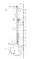
- FIGS. 1 to 11 show a vehicle carrier of the first embodiment
- FIGS. 9 to 11 show the vehicle of the second embodiment. A truck is shown.
- the vehicle carrier of the first embodiment corresponds to claims 1 and 2 of the present application.
- the vehicle transport vehicle according to the first embodiment includes a vehicle 1 having a pair of left and right chassis frames 11 and 11, and subframes 12 and 12 on the chassis frames 11 and 11, respectively.
- Guide rails 2 and 2 fixed to each other, a pair of left and right inclined frames 3 and 3 supported in a tiltable manner at the rear ends of the sub-frames 12 and 12, respectively, and a vehicle longitudinal direction on each of the inclined frames 3 and 3
- a loading platform 4 that is movably supported, and an expansion cylinder 51 that moves the loading platform 4 in the longitudinal direction of the vehicle with respect to the inclined frames 3 and 3, and the inclined frames 3 and 3 are moved by the expansion and contraction of the expansion cylinder 51.
- a tilting device 5 that tilts with respect to the guide rails 2 and 2.
- front or front part refers to the front side of the vehicle 1
- rear or rear part refers to the rear side of the vehicle 1.
- the subframes 12 and 12 are fixed on the left and right chassis frames 11 and 11, respectively.
- the rear ends of the subframes 12 and 12 are connected by a connecting portion 13.
- a sliding contact plate 14 for sliding each bottom frame 42, 42 of the loading platform 4 to be described later at a plurality of positions spaced at appropriate intervals in the sub-frame length direction, 14 are attached (see FIG. 4).
- the chassis without the sub-frame 12 on the chassis frame 11 can be used.
- the sliding contact plates 14, 14,... May be mounted on the chassis frames 11, 11.
- the left and right guide rails 2, 2 are each made of a U-shaped frame material having a predetermined length.
- the guide rails 2 and 2 are fixed to the left and right sub-frames 12 and 12 in a state in which the guide rails 2 and 2 are directed in the vehicle longitudinal direction. When the subframes 12 and 12 are not used, the guide rails 2 and 2 are directly attached to the chassis frames 11 and 11.
- each of the guide rails 2 and 2 is set so that the tilt frames 3 and 3 can be smoothly tilted (at substantially constant speed) when the telescopic cylinder 51 is expanded and contracted.
- each of the guide rails 2 and 2 includes an upward inclined portion 21 inclined upward toward the front portion, a horizontal portion 22 at the intermediate portion, and a downward inclined portion 23 inclined downward toward the rear portion. It is formed continuously.
- the said downward inclination part 23 is an essential structure in this-application Claim 2, in this-application Claim 1, the horizontal part 22 of the guide rail 2 is extended back as it is, and the downward inclination part 23 may be abbreviate
- Each guide rail 2, 2 is formed with an inward guide groove 24 over its entire length. In other embodiments, the guide grooves formed in the guide rails 2 and 2 may be outward guide grooves.
- Each of the inclined frames 3 and 3 is made of a long H-shaped steel (which may be a member having a structure in which U-shaped members are joined back to back).
- Each of the inclined frames 3 and 3 has a length that is considerably longer than the entire length of the chassis frame 11.
- An inward guide groove 31 and an outward guide groove 32 are formed on the left and right sides of each of the inclined frames 3 and 3 over the entire length.
- the inclined frames 3 and 3 are connected by a connecting member 33 in the vicinity of the rear end portion in the length direction.
- a downward support leg 34 is attached to the rear end of each inclined frame 3, 3.
- the support leg 34 is an essential component in claim 2 of the present application.
- a support frame without the support leg 34 can be used.
- the lower surface of the rear end of 3 comes to ground.
- the height of the rear end portion of the tilt frame 3 can be lowered when the tilt frame 3 is tilted rearward and contacted, and the load carrier 4 is moved rearward to the maximum as described later.
- the height of the front end of the loading platform can be further reduced (the loading platform inclination angle in use can be made closer to a horizontal posture).
- Each inclined frame 3, 3 supports a position slightly rearward from the central portion in the length direction on the rear connecting portion 13 of the subframes 12, 12 (support portion 8).
- the support portion 8 is configured such that the brackets 82 and 82 provided on the lower surfaces of the inclined frames 3 and 3 are respectively supported by the brackets 81 and 81 provided on the rear connection portion 13 of the subframe 12. It is pivotally attached at 83.
- the inclined frames 3 and 3 of the first embodiment have a storage posture that is in a horizontal state on the chassis frames 11 and 11 (subframe 12) as shown in FIG. 1, and a support portion 8 as shown in FIG.
- the support leg 34 can be tilted with respect to the rearward tilting posture after being grounded.
- the loading platform 4 has two left and right bottom frames 42, 42 on the lower surface of the vehicle mounting platform 41. Grounding rollers 43 are attached to the lower surfaces of the rear end portions of the bottom frames 42, 42, respectively. Further, a turn plate 44 is attached to the rear end portion of the loading platform 4 so as to be raised and lowered.
- the loading platform 4 can be moved in the vehicle front-rear direction with respect to the inclined frames 3 and 3 via a moving body 6 described later.
- the left and right bottom frames 42, 42 of the loading platform 4 are respectively received on the rear end portions of the inclined frames 3, 3 and the rear end portions (the brackets 81, 81 portions) of the sub-frames 12, 12.
- a pair of receiving rollers 37, 38 (four in front, rear, left and right) are attached.
- Each of the receiving rollers 37 and 38 has the left and right bottom frames 42 and 42 of the loading platform 4 on the bottom surface in the range from the loading platform storage state shown in FIG. 1 to the loading platform rear end (roller 43) shown in FIG. Supporting from the side, the loading platform 4 is moved in a stable state.
- the tilting device 5 is attached to the guide rail 2, one telescopic cylinder 51, and the tube 52 of the telescopic cylinder 51 and moves along the inward guide grooves 24 and 24 of the guide rails 2 and 2.
- Each roller 55 is composed of 55 and 55, which will be described later.
- the rollers 59 and 59 described later are included in one of the constituent elements as the tilting device 5, but in other embodiments, the rollers 59 and 59 may not be used.
- the rollers 59 are removed from the components of the tilting device 5. As shown in FIGS.
- the tube 52 of the telescopic cylinder 51 is provided with a shaft that protrudes left and right outwards at the front end portion and the rear end portion, and a pair of left and right is provided at the tip portion of each shaft.
- Two sets of front and rear rollers front rollers 57, 57 and rear rollers 58, 58) are provided.
- the rollers 57 and 58 may be replaced with sliders (or slide plates).
- the telescopic cylinder 51 has a bracket 36 (see FIGS. 2 and 4) in which the tip of the cylinder rod 53 is provided at the front end of each of the inclined frames 3 and 3 with the cylinder rod 53 facing the front side.
- a pair of left and right rollers 55 and 55 that are a part of the tilting device 5 are attached to the lower end portions of the short downward arms 54 and 54 at positions close to the front portion of the cylinder tube 52 in an outward state, respectively.
- the rails 2 and 2 are fitted into the inward guide grooves 24 and 24.
- the rollers 55 and 55 move back and forth along the inward guide grooves 24 and 24 of the guide rails 2 and 2, respectively. 3 and 3 are tilted about the support portion 8.
- the inclination angle of the downward inclined portion 23 of the guide rail 2 is set so that the inclined frame 3 maintains a substantially constant inclination posture when the roller 55 moves within the range of the downward inclined portion 23. That is, when the roller 55 moves on the downward inclined portion 23, the tilting operation is not performed on the inclined frame 3.
- rollers 59, 59 are attached to the outer surfaces of the downward arms 54, 54 as shown in FIGS.
- the rollers 59 and 59 are fitted into the inward guide grooves 31 and 31 of the left and right inclined frames 3 and 3, similarly to the rollers 57 and 58 attached to the front and rear of the cylinder tube 52.
- one roller 59, 59 is inserted into each guide groove 31, 31, but two rollers 59 are arranged in front of and behind each arm 54, 54, respectively.
- the individual rollers 59 may be fitted into the respective guide grooves 31, 31. In that case, the arms 54 and 54 are guided in a more stable state.
- the loading platform 4 is installed on each of the inclined frames 3 and 3 so that it can be moved back and forth by the double speed device A by an amount twice as large as the expansion / contraction amount of the expansion / contraction cylinder 51.
- This double speed device A is configured to have a moving body 6 and left and right chains 7,7.
- the moving body 6 has left and right frames 61, 61 connected by a connecting plate 62, and two rollers 63, 63,.
- On the left and right sides of the moving body 6 are fitted in the outward guide grooves 32, 32 of the inclined frames 3, 3, respectively, so that the moving body 6 extends along the inclined frames 3, 3.
- the moving body 6 moves back and forth while maintaining a parallel posture with respect to the inclined frames 3 and 3 in a side view.
- Each of the left and right chains 7, 7 has a first divided chain 71 and a second divided chain 72 that are divided into two as shown in FIGS.
- the chain 7 may be a single endless one.
- a wire may be used in place of the chain 7.
- the chains 7 and 7 are attached as follows. First, at the front end portion and the rear end portion of the tube 52 of the telescopic cylinder 51, chain pulleys (total of four) 56, 56,. In this embodiment, the pulleys 56, 56,... Are coaxially installed inside the two front and rear rollers 57, 57, 58, 58, respectively. As shown in FIGS. 3 and 4, each first divided chain 71, 71 is wound around each rear pulley 56, 56 and is connected to the front end of each first divided chain 71, 71. While fixing the portion to the connecting plate 62 of the moving body 6, the rear end portions of the first divided chains 71, 71 are fixed to the inclined frames 3, 3.
- Each of the other second divided chains 72 and 72 is fixed to the connecting plate 62 of the moving body 6 with the front end of each of the second divided chains 72 and 72 being wound around the front pulleys 56 and 56.
- rear end portions of the second divided chains 72 and 72 are fixed to the inclined frames 3 and 3.
- the loading platform 4 is pivotally attached to the moving body 6 at one point by a support shaft (two left and right on the same axis) 64 at a position near the front end of the loading platform. That is, in FIGS. 3 and 4, the shaft holes 64a formed in the left and right frames 61, 61 of the movable body 6 and the shaft holes 64b formed near the front end portions of the left and right bottom frames 42, 42 of the loading platform 4, respectively.
- the shaft 64 see FIGS. 1, 2, and 5
- the loading platform 4 is pivotally attached to the moving body 6 at one point in a side view.
- the double speed device A causes the movable body 6 to adjust the expansion / contraction amount of the expansion / contraction cylinder 51 by the front and rear pulleys 56 and 56 and the chain 7 (first divided chain 71 and second divided chain 72).
- the carriage 4 is moved back and forth by a length twice as long, so that the loading platform 4 is also moved back and forth by the length of twice the expansion / contraction amount of the telescopic cylinder 51 together with the moving body 6.
- the loading platform 4 passes through the inclined state (loading platform tilt angle is about 10 °) where the grounding roller 43 at the rear end of the loading platform shown in FIG. 7, the support leg 34 at the rear end of the inclined frame 3 is brought into contact with the ground, and the loading platform 4 is lowered to a substantially horizontal position near the ground as shown in FIG. .
- the substantially horizontal position in the vicinity of the ground includes a state where the loading platform 4 is grounded at a very gentle inclination angle (for example, about 3 to 4 °).
- the loading platform 4 has a general inclination angle (about 10 °) at which a general high vehicle can be loaded. Sometimes this can be done in the state of FIG. In addition, in the state of this FIG. 6, the back protrusion length of the loading platform 4 becomes short, and becomes effective in the place where the front and back work spaces are narrow.
- the loading platform 4 when the loading platform 4 is lowered to a substantially horizontal position near the ground, it becomes a gentle inclination angle (about 3 to 4 °) at which a low vehicle such as a sports car can be loaded. 8 is carried out in the state shown in FIG. In the state shown in FIG. 8, although the inclination angle of the loading platform 4 can be extremely relaxed, the rear projecting length of the loading platform 4 is increased, and therefore, it is suitable for work in a place where a sufficient working space can be provided. In addition, in the gentle inclination angle state of FIG. 8, it is a matter of course that a general vehicle can be loaded.
- the inclined frame 3 is initially supported at two positions, that is, the support portion 8 (first support location) at the rear end of the subframe 12 and the roller 55 portion (second support location) guided by the guide rail 2.
- the roller 55 moves backward on the guide rail 2 portion, the distance between the support positions at the two positions (the first support position of the support portion 8 and the second support position of the roller 55 portion) gradually decreases.
- the position of the roller 55 (second support location) is reached when the rear end of the loading platform (roller 43) contacts the ground as shown in FIG. ) Is still a considerable distance away from the support portion 8 (first support location) at the rear end of the subframe, so that the posture of the inclined frame 3 still maintains stability.
- the roller 55 (second support location) is still inclined frame from the support portion 8 (first support location) at the rear end portion of the subframe. 3 are separated by a distance that does not impair the stability. Accordingly, during the load carrier grounding operation, until the support leg 34 at the rear end portion of the inclined frame comes into contact with the ground, there is a gap between the two support locations (the first support location 8 and the second support location 55) that support the inclined frame 3. The interval at which the inclined frame 3 can be supported in a stable state is maintained.
- the inclined frame 3 When the support leg 34 at the rear end of the inclined frame is grounded, the inclined frame 3 is considerably separated from the support leg 8 at the rear end of the subframe and the support leg 34 at the rear end of the inclined frame as shown in FIG. Since it is supported at the position, the stability of the posture of the inclined frame 3 is ensured.
- the roller 55 moves rearward on the downward inclined portion 23 of the guide rail 2, and the downward inclined portion 23 is an inclined frame. Since there is no tilting operation with respect to 3, only the loading platform 4 moves backward while the tilting frame 3 is maintained in the posture (the height of the front portion of the loading platform is lowered). As shown in FIG. 8, when the front end of the loading platform is retracted to a position reaching the vicinity of the rear end of the inclined frame 3, the loading platform 4 has a very gentle inclination angle (for example, the inclination angle is about 3 to 4 °). Become.
- the telescopic cylinder 51 is fully contracted, the roller 55 of the downward arm 54 is in a position closer to the front portion of the guide rail 2 (in front of the upward inclined portion 21), and the inclined frame 3 is in a horizontal posture.
- the loading platform 4 also maintains a horizontal posture at the foremost position.
- the positions close to the front end portions of the loading platform bottom frames 42 and 42 are supported by the movable body 6 by the support shaft 64, while the upper surfaces (sliding contact) of the subframes 12 and 12 are supported.
- the bottom surfaces of the loading platform bottom frames 42, 42 are slidably mounted on the plates 14, 14,.
- the telescopic cylinder 51 In order to operate the loading platform 4 to the vehicle loading posture, the telescopic cylinder 51 is extended. Then, the cylinder tube 52 moves rearward, and rollers (a pair of left and right) 55 attached to the downward arm 54 move to the horizontal portion 22 through the upward inclined portion 21 of the guide rail 2 to tilt the inclined frame 3. At the same time, the loading platform 4 is moved backward by twice the extension amount of the telescopic cylinder by the double speed device A, and the grounding roller 43 at the rear end of the loading platform contacts the ground. Thereafter, when the cover plate 44 is laid down and brought into contact with the ground, the general vehicle S can be loaded as shown in FIG.
- the telescopic cylinder 51 is further extended. Then, as shown in FIG. 7, first, when the roller 55 of the downward arm 54 reaches the start end position of the descending inclined portion 23 of the guide rail 2, the support leg 34 at the rear end portion of the inclined frame contacts the ground. At this time, although the inclination angle of the loading platform 4 is smaller than the inclination angle of the inclined frame 3, the loading platform 4 has one point (the position of the support shaft 64) at the front end of the loading platform with respect to the inclined frame 3 (substantially the moving body 6). Since it can tilt about the center, the platform 4 can be tilted with respect to the tilt frame 3 without any trouble.
- the loading platform 4 is lowered to a substantially horizontal position near the ground, and the loading platform 4 is stable at a very gentle inclination angle (for example, about 3 to 4 °).
- a very gentle inclination angle for example, about 3 to 4 °.
- the telescopic cylinder 51 can be extended steplessly between the first-stage extended state in FIG. 6 and the final extended state in FIG. 8, and is set at a loading platform inclination angle corresponding to the vehicle height of the transported vehicle S.
- the rearward protruding length of the loading platform 4 can be set according to the work space and the terrain (for example, it can be used in the state of FIG. 7).
- the tilting frame 3 can be tilted and the loading platform 4 can be moved back and forth simultaneously with one telescopic cylinder 51.
- the tilting device 5 of the tilting frame 3 is composed of the guide rail 2, the telescopic cylinder 51, and the roller 55 attached to the cylinder tube 52, the configuration of the tilting device 5 becomes simple (the number of parts is small, (Assembly becomes good) and light weight, and the whole can be manufactured at low cost.
- the loading / unloading operation of the loading platform 4 is performed by one telescopic cylinder 51.
- two telescopic cylinders 51 are used. You may make it arrange
- a configuration for tilting the tilted frame 3 smoothly can be easily manufactured as compared with a link type device.
- the loading platform 4 can be moved by an amount twice as large as the expansion / contraction amount of the expansion / contraction cylinder 51 using the double speed device A.
- the work can be completed in a short time as compared with the vehicle transporting vehicle, and the moving amount of the loading platform for lowering the loading platform to a substantially horizontal position near the ground can be secured sufficiently.
- FIGS. 9 to 11 The vehicle transport vehicle of the second embodiment shown in FIGS. 9 to 11 corresponds to claim 3 of the present application, and the rear end portion (support leg 34) of the tilt frame 3 is preferably as much as possible when the loading platform 4 is moved backward and tilted. It is designed to be able to ground quickly.
- the vehicle transport vehicle of the second embodiment is a modification of the support portion 8 of the tilt frame 3 in the first embodiment, and the tilt frame is provided at the rear end portion of the subframe 12 as the support portion 8 of the tilt frame 3. 3 is provided so as to support 3 in a freely movable manner.
- another telescopic cylinder 9 for moving the inclined frame 3 back and forth is installed between the rear end of the chassis frame 11 and the inclined frame 3.
- FIGS. 9 to 11 are the same as those of the first embodiment (FIGS. 1 to 8), and the description of the first embodiment is incorporated herein.
- the inclined frame 3 is placed on the roller 84 at the rear end portion (supporting portion 8) of the subframe 12, and the inclined frame 3 is dedicated to the subframe 12.
- the telescopic cylinder 9 can be moved back and forth within a predetermined length range. Then, by moving the tilt frame 3 back and forth with the telescopic cylinder 9, the tilt center position of the tilt frame 3 (portion supported by the roller 84 of the support portion 8) can be moved back and forth. That is, when the telescopic cylinder 9 dedicated to the forward / backward movement of the tilt frame is extended from the loading platform retracted state of FIG. 9, the tilt frame 3 is moved backward by the extension amount. The supported position is displaced toward the front side of the inclined frame 3 by the length of the rearward movement. At this time, the distance from the support part 8 of the inclination frame 3 to the rear end (support leg 34) of the inclination frame becomes long.
- the load applied to the roller 55 is preferably as short as possible and as small as possible. Note that when the support leg 34 is grounded, the load applied to the inclined frame 3 can be received by the support leg 4 and the support portion 8, so that the load on the roller 55 is hardly applied.
- the support leg 34 is more than that of the first embodiment. Since the contact is made quickly, the load time applied to the roller 55 can be shortened, and the load on the roller 55 can be reduced.
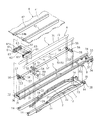
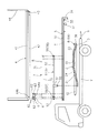
- FIG. 2 is a partially enlarged plan view of the vehicle transport vehicle of FIG. 1. It is an exploded view of the vehicle transport vehicle of FIG. It is a partial perspective view in the decomposition
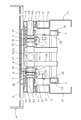
- FIG. 5 is an enlarged VV sectional view of FIG. 1.
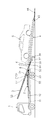
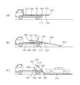
- FIG. 2 is a side view of the vehicle carrier normal inclination angle state in the vehicle transport vehicle of FIG. 1. It is a side view of the transition process from the state of FIG. 6 to a load carrier gentle inclination angle state.
- FIG. 2 is a side view of the vehicle carrier in FIG.
- FIG. 10 is an exploded view of the vehicle transport vehicle of FIG. 9.
- FIG. 10 is a side view of the vehicle carrier of FIG. It is explanatory drawing of a well-known vehicle transport vehicle. It is a partially expanded perspective view in the vehicle transport vehicle of FIG.
- 1 is a vehicle (carrier vehicle), 2 is a guide rail, 3 is an inclined frame, 4 is a loading platform, 5 is a tilting device, 6 is a moving body, 7 is a chain, 8 is a support, 9 is a telescopic cylinder, and 11 is a chassis frame.
- 12 is a sub-frame, 21 is an upward inclined portion, 22 is a horizontal portion, 23 is a downward inclined portion, 34 is a support leg, 51 is a telescopic cylinder, 52 is a cylinder tube, 53 is a cylinder rod, 54 is a downward arm, and 55 is A roller, 84 is a roller, and A is a double speed device.
Landscapes
- Engineering & Computer Science (AREA)
- Health & Medical Sciences (AREA)
- Public Health (AREA)
- Transportation (AREA)
- Mechanical Engineering (AREA)
- Body Structure For Vehicles (AREA)
- Auxiliary Methods And Devices For Loading And Unloading (AREA)
- Fittings On The Vehicle Exterior For Carrying Loads, And Devices For Holding Or Mounting Articles (AREA)
Abstract
Description
本願請求項1の発明の車輌運搬車は、シャシフレームを有する車輌と、シャシフレームの後端部位置において傾動自在に支持された傾斜フレームと、傾斜フレーム上に車輌前後方向に移動自在に支持された荷台と、傾斜フレームと荷台間に設けられていて荷台を傾斜フレームに対して車輌前後方向に移動させる伸縮シリンダを有し且つ伸縮シリンダの伸縮動によって前記傾斜フレームを傾動させ得るようにした傾動装置とを備えたものである。
本願請求項2の発明は、上記請求項1の車輌運搬車において、次の構成を付加したものである。
本願請求項3の発明は、上記請求項1又は2の車輌運搬車において、シャシフレームの後端部にローラを取付けて、該ローラ上に傾斜フレームをシャシフレームに対して前後移動可能に載置しているとともに、シャシフレームの後端部と傾斜フレームとの間に、傾斜フレームを前後移動させる専用の伸縮シリンダを設けている。
本願請求項1の発明の車輌運搬車は、単一の伸縮シリンダで傾斜フレームの傾動と荷台の前後移動を同時に行わせるようにしたものにおいて、次のような効果がある。
本願の車輌運搬車では、荷台接地操作時において、ローラがガイドレールに沿って後方移動すると、傾斜フレームに対する2つの支持位置(シャシフレーム後端部の支持部とローラ部分)が近づいて傾斜フレームの姿勢が漸次不安定になっていくが、本願請求項2の発明では、ローラがガイドレールの下り傾斜部の始端部に達した時点で傾斜フレーム後端部の支持脚が接地するようにしているので、ローラ(第2支持箇所)がシャシフレーム後端部の支持部(第1支持箇所)に余裕をもって近づいた時点で、傾斜フレームをシャシフレーム後端部の支持部と支持脚とで支持できる。
本願請求項3の発明の車輌運搬車では、傾斜フレーム前後移動専用の伸縮シリンダにより傾斜フレームをシャシフレームに対して後方に移動させることで、シャシフレーム後端部の支持部から傾斜フレーム後端部までの距離を長くできる。そして、その状態で荷台接地操作を行うと、傾斜フレームの傾動によって傾斜フレーム後端部が接地するまでの時間を短かくできる。
この第1実施例の車輌運搬車は、本願の請求項1と請求項2に対応するものである。そして、この第1実施例の車輌運搬車は、図1~図5に示すように、左右一対のシャシフレーム11,11を有する車輌1と、各シャシフレーム11,11上のサブフレーム12,12に固定されたガイドレール2,2と、サブフレーム12,12の後端部においてそれぞれ傾動自在に支持された左右一対の傾斜フレーム3,3と、各傾斜フレーム3,3上に車輌前後方向に移動自在に支持された荷台4と、荷台4を傾斜フレーム3,3に対して車輌前後方向に移動させる伸縮シリンダ51を有し且つ該伸縮シリンダ51の伸縮動によって傾斜フレーム3,3を荷台4と共にガイドレール2,2に対して傾動させる傾動装置5とを備えて構成されている。
伸縮シリンダ51のチューブ52には、図2及び図4に示すように、その前端部及び後端部にそれぞれ左右外向きに突出する軸を設けて該各軸の先端部にそれぞれ左右一対とする前後2組のローラ(前ローラ57,57、後ローラ58,58)を設けている。尚、他の実施例では、このローラ57,58に替えてスライダー(又はスライドプレート)で構成してもよい。そして、この伸縮シリンダ51は、シリンダロッド53を前部側に向けた状態で、該シリンダロッド53の先端部を各傾斜フレーム3,3の前端部に設けたブラケット36(図2、図4参照)に支軸35(図2参照)で連結するとともに、シリンダチューブ52の前後各端部に設けた前後2組の各ローラ57,57、58,58をそれぞれ左右の傾斜フレーム3,3の各内向きガイド溝31,31に沿って転動するようにして取付けている。従って、この伸縮シリンダ51は、伸縮時に傾斜フレーム3に対してシリンダチューブ52側が移動し、且つ前後・左右(合計4つ)の各ローラ57,57、58,58がそれぞれ各傾斜フレーム3,3の内向きガイド溝31,31に沿って移動するので、側面視において伸縮シリンダ51が傾斜フレーム3に対して平行姿勢を維持したままで伸縮するようになっている。
図9~図11に示す第2実施例の車輌運搬車は、本願請求項3に対応するもので、荷台4の後方移動及び傾動時に、傾斜フレーム3の後端部(支持脚34)をなるべく早く接地させることができるようにしたものである。
から支持脚34が接地するまでの傾動角度が図7及び図8(第1実施例)の場合よりも小さくなり、従ってその分、支持脚34が接地するまでの時間が短くなる。
Claims (3)
- シャシフレーム(11)を有する車輌(1)と、前記シャシフレーム(11)の後端部位置において傾動自在に支持された傾斜フレーム(3)と、該傾斜フレーム(3)上に車輌前後方向に移動自在に支持された荷台(4)と、前記傾斜フレーム(3)と前記荷台(4)間に設けられていて該荷台(4)を前記傾斜フレーム(3)に対して車輌前後方向に移動させる伸縮シリンダ(51)を有し且つ該伸縮シリンダ(51)の伸縮動によって前記傾斜フレーム(3)を傾動させ得るようにした傾動装置(5)とを備えた車輌運搬車であって、
前記傾動装置(5)は、シャシフレーム(11)に取付けたガイドレール(2)と、前記伸縮シリンダ(51)と、該伸縮シリンダ(51)のチューブ(52)に取付けられていて前記ガイドレール(2)に沿って移動するローラ(55)とで構成している一方、
前記傾斜フレーム(3)と前記荷台(4)間に、前記伸縮シリンダ(51)の伸縮量に対して該荷台(4)を2倍の量だけ前後移動させ得るようにした倍速装置(A)を設けているとともに、
前記伸縮シリンダ(51)の伸長動で、前記傾動装置(5)による前記傾斜フレーム(3)の後傾作動と前記荷台(4)の後方移動とを同時に行わせて前記荷台(4)を地上近傍の略水平位置まで降下させ得るようにしている、
ことを特徴とする車輌運搬車。 - 請求項1において、
前記傾斜フレーム(3)の後端部に下向きの支持脚(34)を設け、
前記ガイドレール(2)には車輌前部側から上り傾斜部(21)と水平部(22)と下り傾斜部(23)とを連続して形成し、
前記下り傾斜部(23)の傾斜角を、前記ローラ(55)が前記下り傾斜部(23)の範囲を移動する際に前記傾斜フレーム(3)が略一定の傾斜姿勢を維持するように設定しているとともに、
前記ローラ(55)が前記下り傾斜部(23)に位置している状態では前記支持脚(34)が地面に接地するようにしている、
ことを特徴とする車輌運搬車。 - 請求項1又は2において、
前記シャシフレーム(11)の後端部にローラ(84)を取付けて、該ローラ(84)上に前記傾斜フレーム(3)をシャシフレーム(11)に対して前後移動可能に載置しているとともに、
前記シャシフレーム(11)の後端部と前記傾斜フレーム(3)との間に、該傾斜フレーム(3)を前後移動させる専用の伸縮シリンダ(9)を設けている、
ことを特徴とする車輌運搬車。
Priority Applications (3)
| Application Number | Priority Date | Filing Date | Title |
|---|---|---|---|
| PCT/JP2008/062310 WO2010004615A1 (ja) | 2008-07-08 | 2008-07-08 | 車輌運搬車 |
| KR1020107029150A KR101467019B1 (ko) | 2008-07-08 | 2008-07-08 | 차량 운반차 |
| CN200880130316.5A CN102099223B (zh) | 2008-07-08 | 2008-07-08 | 车辆运输车 |
Applications Claiming Priority (1)
| Application Number | Priority Date | Filing Date | Title |
|---|---|---|---|
| PCT/JP2008/062310 WO2010004615A1 (ja) | 2008-07-08 | 2008-07-08 | 車輌運搬車 |
Publications (1)
| Publication Number | Publication Date |
|---|---|
| WO2010004615A1 true WO2010004615A1 (ja) | 2010-01-14 |
Family
ID=41506749
Family Applications (1)
| Application Number | Title | Priority Date | Filing Date |
|---|---|---|---|
| PCT/JP2008/062310 Ceased WO2010004615A1 (ja) | 2008-07-08 | 2008-07-08 | 車輌運搬車 |
Country Status (3)
| Country | Link |
|---|---|
| KR (1) | KR101467019B1 (ja) |
| CN (1) | CN102099223B (ja) |
| WO (1) | WO2010004615A1 (ja) |
Cited By (6)
| Publication number | Priority date | Publication date | Assignee | Title |
|---|---|---|---|---|
| JP2010260402A (ja) * | 2009-04-30 | 2010-11-18 | San Jidosha Kogyo:Kk | スライド部構造 |
| US8215717B2 (en) | 2010-02-26 | 2012-07-10 | All Right Steel, Llc | Dump trailer |
| US8876216B2 (en) | 2010-02-26 | 2014-11-04 | All Right Steel, Llc | Dump trailer |
| EP3012149A3 (de) * | 2014-10-24 | 2016-05-25 | Marbach Concepte GmbH & Co. KG | Fahrzeug zum transportieren von zumindest einem pkw |
| US20170057392A1 (en) * | 2014-03-03 | 2017-03-02 | Pivottray Pty Ltd | A Repositionable Load Carrying Tray Assembly for a Vehicle |
| JP2019182326A (ja) * | 2018-04-16 | 2019-10-24 | 株式会社花見台自動車 | 歩み板 |
Families Citing this family (1)
| Publication number | Priority date | Publication date | Assignee | Title |
|---|---|---|---|---|
| FR3157301A1 (fr) * | 2023-12-21 | 2025-06-27 | Stellantis Auto Sas | Véhicule à plateau mobile entre une position de chargement et une position de transport. |
Citations (5)
| Publication number | Priority date | Publication date | Assignee | Title |
|---|---|---|---|---|
| JPS5890841U (ja) * | 1981-12-16 | 1983-06-20 | 株式会社花見台自動車 | 貨物自動車 |
| JP2000006708A (ja) * | 1998-06-22 | 2000-01-11 | Tadano Ltd | 車輌運搬車の荷台傾斜装置 |
| JP2004017795A (ja) * | 2002-06-17 | 2004-01-22 | Hanamidai Jidosha:Kk | 荷台移動傾斜装置 |
| JP2004231130A (ja) * | 2003-01-31 | 2004-08-19 | Furukawa Co Ltd | 貨物自動車の荷台傾斜装置 |
| JP2007276744A (ja) * | 2006-04-12 | 2007-10-25 | Tadano Ltd | 車両運搬車の荷台移動装置 |
Family Cites Families (4)
| Publication number | Priority date | Publication date | Assignee | Title |
|---|---|---|---|---|
| JP2529706Y2 (ja) * | 1991-03-30 | 1997-03-19 | 極東開発工業株式会社 | 貨物自動車 |
| CN2533012Y (zh) * | 2001-10-24 | 2003-01-29 | 重汽集团专用汽车公司 | 卷筒式软布自动车厢盖 |
| JP4583879B2 (ja) * | 2004-11-01 | 2010-11-17 | 株式会社タダノ | 車輌運搬車 |
| JP4630720B2 (ja) * | 2005-04-18 | 2011-02-09 | 株式会社花見台自動車 | 貨物自動車 |
-
2008
- 2008-07-08 KR KR1020107029150A patent/KR101467019B1/ko active Active
- 2008-07-08 CN CN200880130316.5A patent/CN102099223B/zh active Active
- 2008-07-08 WO PCT/JP2008/062310 patent/WO2010004615A1/ja not_active Ceased
Patent Citations (5)
| Publication number | Priority date | Publication date | Assignee | Title |
|---|---|---|---|---|
| JPS5890841U (ja) * | 1981-12-16 | 1983-06-20 | 株式会社花見台自動車 | 貨物自動車 |
| JP2000006708A (ja) * | 1998-06-22 | 2000-01-11 | Tadano Ltd | 車輌運搬車の荷台傾斜装置 |
| JP2004017795A (ja) * | 2002-06-17 | 2004-01-22 | Hanamidai Jidosha:Kk | 荷台移動傾斜装置 |
| JP2004231130A (ja) * | 2003-01-31 | 2004-08-19 | Furukawa Co Ltd | 貨物自動車の荷台傾斜装置 |
| JP2007276744A (ja) * | 2006-04-12 | 2007-10-25 | Tadano Ltd | 車両運搬車の荷台移動装置 |
Cited By (7)
| Publication number | Priority date | Publication date | Assignee | Title |
|---|---|---|---|---|
| JP2010260402A (ja) * | 2009-04-30 | 2010-11-18 | San Jidosha Kogyo:Kk | スライド部構造 |
| US8215717B2 (en) | 2010-02-26 | 2012-07-10 | All Right Steel, Llc | Dump trailer |
| US8876216B2 (en) | 2010-02-26 | 2014-11-04 | All Right Steel, Llc | Dump trailer |
| US20170057392A1 (en) * | 2014-03-03 | 2017-03-02 | Pivottray Pty Ltd | A Repositionable Load Carrying Tray Assembly for a Vehicle |
| US9840180B2 (en) * | 2014-03-03 | 2017-12-12 | Pivottray Pty Ltd | Repositionable load carrying tray assembly for a vehicle |
| EP3012149A3 (de) * | 2014-10-24 | 2016-05-25 | Marbach Concepte GmbH & Co. KG | Fahrzeug zum transportieren von zumindest einem pkw |
| JP2019182326A (ja) * | 2018-04-16 | 2019-10-24 | 株式会社花見台自動車 | 歩み板 |
Also Published As
| Publication number | Publication date |
|---|---|
| CN102099223B (zh) | 2014-03-05 |
| KR101467019B1 (ko) | 2014-12-01 |
| CN102099223A (zh) | 2011-06-15 |
| KR20110036710A (ko) | 2011-04-08 |
Similar Documents
| Publication | Publication Date | Title |
|---|---|---|
| WO2010004615A1 (ja) | 車輌運搬車 | |
| JP4974705B2 (ja) | 車輌運搬車 | |
| JP2008207573A5 (ja) | ||
| KR101592363B1 (ko) | 사다리차용 운반대차 장치 | |
| JP5224987B2 (ja) | 車輌運搬車 | |
| JP2009006765A (ja) | 貨物自動車用荷台昇降装置、およびこれを備える貨物自動車 | |
| JP5536422B2 (ja) | 貨物自動車用荷台昇降装置、およびこれを備える貨物自動車 | |
| JP6285262B2 (ja) | 貨物自動車用バンパ装置およびこれを備える貨物自動車 | |
| JP5261166B2 (ja) | 車輌運搬車における荷台移動用の伸縮シリンダ組立構造 | |
| JP5581149B2 (ja) | 荷台移動式運搬車 | |
| JP5411647B2 (ja) | 車輌運搬車の荷台調芯装置 | |
| JP4583879B2 (ja) | 車輌運搬車 | |
| JP2019025958A (ja) | 荷台移動式運搬車 | |
| JP3110173U (ja) | 格納式荷受台昇降装置 | |
| JP7489735B1 (ja) | 荷台傾斜移動機構及び貨物自動車 | |
| JP2007302085A (ja) | 車輌運搬車の荷台後傾機構 | |
| JP6694586B2 (ja) | 傾斜フレーム傾動装置及びそれを備えた車両運搬車 | |
| JP3619213B2 (ja) | 荷台移動傾斜装置 | |
| CN103786623B (zh) | 车辆运输车 | |
| JP7181500B2 (ja) | 車両運搬車 | |
| JP2007076756A (ja) | 搬送装置 | |
| JP6359944B2 (ja) | 貨物自動車用荷台支持脚およびこれを備える貨物自動車 | |
| JP2015202812A (ja) | 貨物自動車用荷台支持脚およびこれを備える貨物自動車 | |
| JP5422410B2 (ja) | 荷台移動式運搬車における荷台作業状態告知装置 | |
| JP2001105959A (ja) | 車輌運搬車 |
Legal Events
| Date | Code | Title | Description |
|---|---|---|---|
| WWE | Wipo information: entry into national phase |
Ref document number: 200880130316.5 Country of ref document: CN |
|
| 121 | Ep: the epo has been informed by wipo that ep was designated in this application |
Ref document number: 08790947 Country of ref document: EP Kind code of ref document: A1 |
|
| DPE1 | Request for preliminary examination filed after expiration of 19th month from priority date (pct application filed from 20040101) | ||
| ENP | Entry into the national phase |
Ref document number: 20107029150 Country of ref document: KR Kind code of ref document: A |
|
| NENP | Non-entry into the national phase |
Ref country code: DE |
|
| 122 | Ep: pct application non-entry in european phase |
Ref document number: 08790947 Country of ref document: EP Kind code of ref document: A1 |
|
| NENP | Non-entry into the national phase |
Ref country code: JP |