WO2010001592A1 - 伝達比可変機構および車両用操舵装置 - Google Patents
伝達比可変機構および車両用操舵装置 Download PDFInfo
- Publication number
- WO2010001592A1 WO2010001592A1 PCT/JP2009/003026 JP2009003026W WO2010001592A1 WO 2010001592 A1 WO2010001592 A1 WO 2010001592A1 JP 2009003026 W JP2009003026 W JP 2009003026W WO 2010001592 A1 WO2010001592 A1 WO 2010001592A1
- Authority
- WO
- WIPO (PCT)
- Prior art keywords
- inner ring
- transmission ratio
- ratio variable
- variable mechanism
- shaft
- Prior art date
- Legal status (The legal status is an assumption and is not a legal conclusion. Google has not performed a legal analysis and makes no representation as to the accuracy of the status listed.)
- Ceased
Links
Images


Classifications
-
- B—PERFORMING OPERATIONS; TRANSPORTING
- B62—LAND VEHICLES FOR TRAVELLING OTHERWISE THAN ON RAILS
- B62D—MOTOR VEHICLES; TRAILERS
- B62D5/00—Power-assisted or power-driven steering
- B62D5/008—Changing the transfer ratio between the steering wheel and the steering gear by variable supply of energy, e.g. by using a superposition gear
-
- F—MECHANICAL ENGINEERING; LIGHTING; HEATING; WEAPONS; BLASTING
- F16—ENGINEERING ELEMENTS AND UNITS; GENERAL MEASURES FOR PRODUCING AND MAINTAINING EFFECTIVE FUNCTIONING OF MACHINES OR INSTALLATIONS; THERMAL INSULATION IN GENERAL
- F16H—GEARING
- F16H1/00—Toothed gearings for conveying rotary motion
- F16H1/28—Toothed gearings for conveying rotary motion with gears having orbital motion
- F16H1/32—Toothed gearings for conveying rotary motion with gears having orbital motion in which the central axis of the gearing lies inside the periphery of an orbital gear
- F16H1/321—Toothed gearings for conveying rotary motion with gears having orbital motion in which the central axis of the gearing lies inside the periphery of an orbital gear the orbital gear being nutating
-
- Y—GENERAL TAGGING OF NEW TECHNOLOGICAL DEVELOPMENTS; GENERAL TAGGING OF CROSS-SECTIONAL TECHNOLOGIES SPANNING OVER SEVERAL SECTIONS OF THE IPC; TECHNICAL SUBJECTS COVERED BY FORMER USPC CROSS-REFERENCE ART COLLECTIONS [XRACs] AND DIGESTS
- Y10—TECHNICAL SUBJECTS COVERED BY FORMER USPC
- Y10T—TECHNICAL SUBJECTS COVERED BY FORMER US CLASSIFICATION
- Y10T74/00—Machine element or mechanism
- Y10T74/19—Gearing
- Y10T74/19642—Directly cooperating gears
- Y10T74/1966—Intersecting axes
Definitions
- the present invention relates to a transmission ratio variable mechanism and a vehicle steering apparatus.
- Patent Document 1 As a transmission, for example, one using an eccentric gear (for example, see Patent Document 1), one using a planetary gear (for example, see Patent Document 2), or one using a rocking gear (for example, Patent Document 1) 3) is known.
- Patent Documents 2 and 3 describe a transmission that is applied to a vehicle steering system.
- Patent Document 3 includes first and fourth gears that face each other, and an oscillating gear that is disposed between the first and fourth gears and is inclined with respect to the first and fourth gears.
- the swing gear includes a second gear that meshes with the first gear and a third gear that meshes with the fourth gear. These second and third gears are formed as a single member. Therefore, when forming the oscillating gear, the second gear is formed on one end surface of the manufacturing intermediate of the oscillating gear, and then the third gear is formed on the other end surface of the manufacturing intermediate. At this time, the positioning of the third gear must be accurately set with respect to the second gear, and it takes time to manufacture the swing gear.
- the present invention has been made under such a background, and an object thereof is to provide a transmission ratio variable mechanism and a vehicle steering device that can reduce the labor required for manufacturing.
- preferred embodiments of the present invention include an input member rotatable around a first axis, an output member rotatable around the first axis, and first and second end faces. And a first race ring that connects the input member and the output member so as to be differentially rotatable, and a second race ring that rotatably supports the first race ring via a rolling element. And an actuator capable of rotationally driving the second raceway ring.
- a second axis as a central axis of the first and second races is inclined with respect to the first axis.
- the input member and the output member have a power transmission surface facing the corresponding end surface of the first track ring.
- An uneven engagement portion is provided for engaging each end face of the first raceway ring and the power transmission face corresponding to the end face so as to be able to transmit power.
- the concavo-convex engaging portion includes a convex portion provided on one of the end surfaces of the first track ring and the power transmission surface corresponding to the end surface, and a concave portion provided on the other side and engaged with the convex portion.
- the first track ring includes a first member that forms the first end face, and a second member that forms the second end face. The first and second members are formed separately from each other and coupled so as to be able to move together.
- the formation of the convex portions or the concave portions on the first and second end faces of the first raceway ring is performed as follows, for example. That is, a convex portion or a concave portion is formed on one end surface corresponding to the first end surface of the manufacturing intermediate of the first member, and separately from the second end surface of the manufacturing intermediate of the second member. A convex portion or a concave portion is formed by forming a convex portion or a concave portion on the corresponding one end surface.
- the first race ring is an inner ring
- the inner ring has an annular inner ring main body having an inner ring raceway formed on the outer periphery, and the first and second members are fixed to the inner ring main body. If it is, it is preferable.
- the inner ring main body, the first member, and the second member are formed separately. Thereby, about the manufacturing intermediate body of an inner ring
- the inner ring is formed by forming the inner ring raceway in addition to the formation of the concave or convex portions on the pair of end faces of the intermediate body of the first race ring made of a single member. Less time and effort.
- Each of the first and second members includes a cylindrical part fitted to the inner periphery of the inner ring main body, and extends radially outward from the cylindrical part from one end of the cylindrical part. It is preferable that the first and second end surfaces of the inner ring as the first race ring are provided on each of the annular flanges. In this case, the inner ring main body can be sandwiched between the annular flange of the first member and the annular flange of the second member. Thereby, the mutual coupling
- each annular flange extends along the corresponding end surface of the inner ring body, and the other end surface of each annular flange corresponds to the corresponding first and second The second end face is preferable.
- the thrust force that acts on the corresponding end surface of the inner ring from the input member and the thrust force that acts on the corresponding end surface of the inner ring from the output member are forces that each annular flange tightens the inner ring body as a whole.
- the outer periphery of the cylindrical portion of the first and second members includes a press-fit portion that is press-fitted into the inner periphery of the inner ring main body, and a relief recess that is recessed with respect to the press-fit portion.
- a gap is provided between the recess and the inner periphery of the inner ring main body, and the first and second members are interposed between the press-fit portions of the first and second members with respect to the axial direction of the inner ring. It is preferable if the relief recesses are arranged adjacent to each other. In this case, the inner ring main body and the first and second members are press-fitted and coupled. Thereby, sufficient coupling strength between the inner ring main body and the first and second members can be secured.
- a relief recess is provided. Thereby, the fluctuation
- the inner ring raceway and each relief recess are opposed to each other in the radial direction of the inner ring.
- fluctuations in the internal clearance of the bearing due to the inner ring main body being pressed against the press-fit portion can be more reliably suppressed. Therefore, it is easier to manage the internal clearance of the bearing.
- the said cylindrical part of the said 1st and 2nd member contains the opposing edge part which mutually opposes, the fitting recessed part formed in one side of each said opposing edge part, and the fitting convex part formed in the other are preferably fitted to each other so that relative rotation of the first and second members is restricted. In this case, the relative rotation of the first and second members can be reliably restricted.
- each of the opposed end portions is formed in a rectangular wave shape extending in the circumferential direction of the cylindrical portion when viewed along the radial direction of the cylindrical portion.
- the relative rotation of the first and second members can be reliably regulated by the fitting between the fitting concave portion and the fitting convex portion.
- each of the opposed end portions is formed in a triangular wave shape extending in the circumferential direction of the cylindrical portion when viewed along the radial direction of the cylindrical portion. In this case, the relative rotation of the first and second members can be reliably restricted by fitting the triangular wave-shaped fitting concave portion and the fitting convex portion.
- the actuator includes a transmission ratio variable mechanism motor, and the transmission ratio variable mechanism motor is coupled to the second raceway so as to be able to rotate together with the second raceway around the first axis, It is preferable if it has a stator surrounding the rotor.
- the first track ring can be rotated about the first axis by rotating the second track ring about the first axis.
- the first track ring can be Coriolis motion (swing motion).
- corrugated engagement part contains the 1st uneven
- corrugated engagement part is the said power transmission surface of the said input member
- corrugated engaging part are provided in the both sides of the 1st track ring. Thereby, power transmission is possible between an input member and an output member.
- the shaft includes opposite end portions that face each other and includes a support mechanism that supports the opposite end portions so as to be relatively rotatable.
- the runout of the opposing end portions of the first and second shafts can be further reduced.
- the eccentric rotation of the input member and the output member with respect to the first axis can be further reduced, and as a result, an excessive force is applied from the input member and the output member to the first member and the second member of the first race ring. It can suppress more reliably that it acts. As a result, it is possible to more reliably prevent the relative positions of the first and second members from shifting.
- the support mechanism is a bearing provided on the input member and surrounding the opposed end portion of the second shaft, and a bearing interposed between the annular portion and the opposed end portion of the second shaft. And the like are preferable.
- the input member supports the first shaft and supports the opposing end portion of the second shaft via the bearing.
- the transmission member includes a steering member, a steered wheel, and a transmission ratio variable mechanism capable of changing a transmission ratio as a ratio of the steered angle of the steered wheel to the steering angle of the steered member, and the transmission ratio variable mechanism includes the above It is preferable that the transmission ratio variable mechanism is adopted, the input member of the transmission ratio variable mechanism is connected to the steering member, and the output member of the transmission ratio variable mechanism is connected to the steered wheels. In this case, it is possible to realize a vehicle steering apparatus that requires less labor for manufacturing.
- the actuator since it is not necessary to generate a steering assist force by the actuator that drives the second raceway ring, the actuator can be made inexpensive and small.
- a shaft interposed between the output member and the steered wheel is provided, and the steering assist force application mechanism transmits a second actuator that generates a steering assist force and the steering assist force to the shaft.
- the steering assist force of the second actuator is transmitted to the steered wheels via a shaft or the like, and is transmitted to the steered wheels without going through the transmission ratio variable mechanism.
- the large torque from the second actuator can be prevented from being transmitted to the transmission ratio variable mechanism, and therefore the allowable torque of each component of the transmission ratio variable mechanism can be further reduced.
- the manufacturing cost of each component of the transmission ratio variable mechanism can be further reduced.
- the torque acting between the first member and the second member of the first track ring can be small, and the relative positions of the first and second members can be more reliably prevented from shifting.
- FIG. 3 is an enlarged view of a transmission ratio variable mechanism in FIG. 2 and its surroundings. It is the side view which represented the principal part of the transmission ratio variable mechanism with the cross section.
- FIG. 3 is an enlarged view of a transmission ratio variable mechanism in FIG. 2 and its surroundings. It is the side view which represented the principal part of the transmission ratio variable mechanism with the cross section.
- FIG. 3 is an enlarged view of a transmission ratio variable mechanism in FIG. 2 and its surroundings. It is the side view which represented the principal part of the transmission ratio variable mechanism with the cross section.
- FIG. 3 is an enlarged view of a transmission ratio variable mechanism in FIG. 2 and its surroundings. It is the side view which represented the principal part of the transmission ratio variable mechanism with the cross section.
- FIG. 1 is a schematic diagram showing a schematic configuration of a vehicle steering apparatus 1 including a transmission ratio variable mechanism according to an embodiment of the present invention.
- a vehicle steering apparatus 1 applies a steering torque applied to a steering member 2 such as a steering wheel to left and right steered wheels 4L and 4R via a steering shaft 3 as a steering shaft.
- the steering is given.
- This vehicle steering apparatus 1 has a VGR (Variable Gear Ratio) function capable of changing a transmission ratio ⁇ 2 / ⁇ 1 as a ratio of a steered wheel turning angle ⁇ 2 to a steering angle ⁇ 1 of a steering member 2. .
- VGR Vehicle Gear Ratio
- the vehicle steering apparatus 1 includes a steering member 2 and a steering shaft 3 connected to the steering member 2.
- the steering shaft 3 includes first to third shafts 11 to 13 arranged coaxially with each other.
- the first axis A as the central axis of the first to third shafts 11 to 13 is also the rotational axis of the first to third shafts 11 to 13.
- a steering member 2 is connected to one end of the first shaft 11 so as to be able to rotate together.
- the other end of the first shaft 11 and one end of the second shaft 12 are coupled via a transmission ratio variable mechanism 5 so as to be differentially rotatable.
- the other end of the second shaft 12 and one end of the third shaft 13 are connected via a torsion bar 14 so that they can be elastically rotated relative to each other and can transmit power.
- the other end of the third shaft 13 is connected to the steered wheels 4L and 4R via the universal joint 7, the intermediate shaft 8, the universal joint 9, the steering mechanism 10, and the like.
- the steered mechanism 10 includes a pinion shaft 15 connected to the universal joint 9, and a rack shaft 16 as a steered shaft that has a rack 16a that meshes with the pinion 15a at the tip of the pinion shaft 15 and extends in the left-right direction of the vehicle. Yes.
- Knuckle arms 18L and 18R are connected to the pair of ends of the rack shaft 16 via tie rods 17L and 17R, respectively.
- the rotation of the steering member 2 is transmitted to the steering mechanism 10 via the steering shaft 3 or the like.
- the rotation of the pinion 15 a is converted into the axial movement of the rack shaft 16.
- the axial movement of the rack shaft 16 is transmitted to the corresponding knuckle arms 18L and 18R via the tie rods 17L and 17R.
- these knuckle arms 18L and 18R rotate.
- the corresponding steered wheels 4L and 4R connected to the knuckle arms 18L and 18R are respectively steered.
- the transmission ratio variable mechanism 5 is for changing the rotation transmission ratio (transmission ratio ⁇ 2 / ⁇ 1) between the first and second shafts 11 and 12 of the steering shaft 3, and is a nutation gear mechanism. .
- the transmission ratio variable mechanism 5 includes an input member 20 provided at the other end of the first shaft 11, an output member 22 provided at one end of the second shaft 12, and the input member 20 and the output member 22. And a bearing ring unit 39 as an intermediate member interposed therebetween.
- the input member 20 is connected to the steering member 2 and the first shaft 11 so as to be coaxial and rotatable.
- the output member 22 is connected to the second shaft 12 so as to be coaxial and rotatable.
- the first axis A is also the center axis and the rotation axis of the input member 20 and the output member 22.
- the output member 22 is connected to the steered wheels 4L and 4R via the second shaft 12, the steered mechanism 10, and the like.
- the bearing ring unit 39 includes an inner ring 391 as a first bearing ring, an outer ring 392 as a second bearing ring, and rolling elements 393 such as balls interposed between the inner ring 391 and the outer ring 392. .
- the bearing ring unit 39 constitutes a four-point contact bearing.
- the rolling element 393, a cylindrical roller, a needle roller, and a tapered roller can be used besides a ball.
- the rolling elements 393 may be arranged in a single row, or may be arranged in a double row. If the rolling elements 393 are arranged in a double row, the inner ring 391 can be prevented from falling over the outer ring 392.
- An example of the bearing having the double row rolling elements 393 is a double row angular bearing.
- the inner ring 391 connects the input member 20 and the output member 22 so as to be differentially rotatable.
- the inner ring 391 and the outer ring 392 have a second axis B as a central axis inclined with respect to the first axis A.
- the second axis B is inclined at a predetermined inclination angle with respect to the first axis A.
- the inner ring 391 is rotatable around the second axis B by being rotatably supported by the outer ring 392 via the rolling elements 393. Further, the inner ring 391 can rotate around the first axis A as the transmission ratio variable mechanism motor 23, which is an electric motor as an actuator for driving the outer ring 392, is driven.
- the inner ring 391 and the outer ring 392 can perform Coriolis motion (swing motion) around the first axis A.
- the transmission ratio variable mechanism motor 23 is disposed radially outward of the bearing ring unit 39, and the first axis A is the central axis.
- the transmission ratio variable mechanism motor 23 changes the transmission ratio ⁇ 2 / ⁇ 1 by changing the number of rotations of the outer ring 392 around the first axis A.
- the transmission ratio variable mechanism motor 23 is composed of, for example, a brushless motor arranged coaxially with the steering shaft 3.
- the transmission ratio variable mechanism motor 23 includes a rotor 231 that holds the outer ring 392 of the raceway ring unit 39 and a stator 232 that surrounds the rotor 231.
- the stator 232 is fixed to a housing 24 as a steering column.
- the rotor 231 rotates around the first axis A.
- the vehicle steering apparatus 1 includes a steering assist force applying mechanism 19 for applying a steering assist force to the steering shaft 3.
- the steering assist force applying mechanism 19 includes the second shaft 12 as an input shaft continuous with the output member 22 of the transmission ratio variable mechanism 5, the third shaft 13 as an output shaft continuous with the steering mechanism 10, A torque sensor 44 for detecting torque transmitted between the second shaft 12 and the third shaft 13; a steering assist motor 25 as a second actuator for steering assist; a steering assist motor 25; 3 and a speed reduction mechanism 26 as a transmission mechanism interposed between the three shafts 13.
- the steering assist motor 25 generates a steering assist force, and includes an electric motor such as a brushless motor.
- the output of the steering assist motor 25 is transmitted to the third shaft 13 via the speed reduction mechanism 26 as a steering assist force.
- the third shaft 13 is a shaft interposed in the torque transmission path between the output member 22 and the steered wheels 4L and 4R.
- the speed reduction mechanism 26 is, for example, a worm gear mechanism, and is connected to a worm shaft 27 as a drive gear connected to the output shaft 25a of the steering assist motor 25, and engages with the worm shaft 27 so as to be able to rotate together with the third shaft 13.
- a worm gear 28 as a driven gear.
- the speed reduction mechanism 26 is not limited to the worm gear mechanism, and other gear mechanisms such as a parallel shaft gear mechanism using a spur gear or a helical gear may be used.
- the transmission ratio variable mechanism 5 and the steering assist force applying mechanism 19 are provided in the housing 24.
- the housing 24 is disposed in a passenger compartment (cabin) of the vehicle.
- the housing 24 may be disposed so as to surround the intermediate shaft 8 or may be disposed in the engine room of the vehicle.
- the driving of the transmission ratio variable mechanism motor 23 and the steering assist motor 25 is controlled by a control unit 29 including a CPU, a RAM, and a ROM, respectively.
- the control unit 29 is connected to the transmission ratio variable mechanism motor 23 via the drive circuit 40, and is connected to the steering assist motor 25 via the drive circuit 41.
- the control unit 29 includes a steering angle sensor 42, a motor resolver 43 as a rotation angle detection means for detecting the rotation angle of the transmission ratio variable mechanism motor 23, a torque sensor 44 as a torque detection means, and a turning angle sensor 45.
- a vehicle speed sensor 46 and a yaw rate sensor 47 are connected to each other.
- a signal about the rotation angle of the first shaft 11 is transmitted from the steering angle sensor 42 to the control unit 29 as a value corresponding to the steering angle ⁇ 1 that is the operation amount of the steering member 2 from the position of the steering member 2 when the vehicle is traveling straight ahead. Is entered.
- a signal regarding the rotation angle ⁇ r of the rotor 231 of the transmission ratio variable mechanism motor 23 is input from the motor resolver 43 to the control unit 29.
- a signal regarding the torque acting between the second and third shafts 12 and 13 is input from the torque sensor 44 to the control unit 29.
- a signal about the rotation angle of the third shaft 13 is input from the turning angle sensor 45 to the control unit 29 as a value corresponding to the turning angle ⁇ 2.
- a signal regarding the vehicle speed V is input from the vehicle speed sensor 46 to the control unit 29.
- a signal regarding the yaw rate ⁇ of the vehicle is input from the yaw rate sensor 47 to the control unit 29.
- the control unit 29 controls the drive of the transmission ratio variable mechanism motor 23 and the steering assist motor 25 based on the signals of the sensors 42 to 47 and the like.
- the output of the transmission ratio variable mechanism 5 is transmitted to the steering mechanism 10 via the steering assist force applying mechanism 19. More specifically, the steering torque input to the steering member 2 is input to the input member 20 of the transmission ratio variable mechanism 5 via the first shaft 11, and the steering assist force applying mechanism 19 of the steering assist force applying mechanism 19 is changed from the output member 22. Is transmitted to the second shaft 12. The steering torque transmitted to the second shaft 12 is transmitted to the torsion bar 14 and the third shaft 13, and is combined with the output from the steering assist motor 25, and further to the steering mechanism 10 via the intermediate shaft 8 and the like. Communicated.
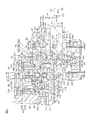
- FIG. 2 is a cross-sectional view showing a more specific configuration of the main part of FIG.
- the housing 24 is formed by forming a metal such as an aluminum alloy into a cylindrical shape.
- the housing 24 includes first to third housings 51 to 53.
- first to eighth bearings 31 to 38 are accommodated.
- the first to fifth bearings 31 to 35 and the seventh to eighth bearings 37 to 38 are rolling bearings such as angular ball bearings.
- the sixth bearing 36 is a rolling bearing such as a needle roller bearing.
- the first housing 51 has a cylindrical shape, constitutes a differential mechanism housing that houses the transmission ratio variable mechanism 5 as a differential mechanism, and a motor housing that houses the transmission ratio variable mechanism motor 23. It is composed.
- One end of the first housing 51 is covered with an end wall member 54.
- One end of the first housing 51 and the end wall member 54 are fixed to each other using a fastening member 55 such as a bolt.
- An annular convex portion 57 at one end of the second housing 52 is fitted to the inner peripheral surface 56 at the other end of the first housing 51.
- the first and second housings 51 and 52 are fixed to each other using a fastening member (not shown) such as a bolt.
- the second housing 52 has a cylindrical shape, and constitutes a sensor housing that houses the torque sensor 44 and a resolver housing that houses the motor resolver 43.
- the second housing 52 accommodates a bus bar 99 described later of the transmission ratio variable mechanism motor 23 and a lock mechanism 58 for locking the rotor 231 of the transmission ratio variable mechanism motor 23.
- the inner peripheral surface 60 at one end of the third housing 53 is fitted to the outer peripheral surface 59 at the other end of the second housing 52.
- the third housing 53 has a cylindrical shape and constitutes a speed reduction mechanism housing that houses the speed reduction mechanism 26.
- An end wall portion 61 is provided at the other end of the third housing 53.
- the end wall portion 61 has an annular shape and covers the other end of the third housing 53.
- FIG. 3 is an enlarged view of the transmission ratio variable mechanism 5 of FIG. 2 and its surroundings. Referring to FIG. 3, the input member 20, the output member 22 of the transmission ratio variable mechanism 5, and the inner ring 391 of the raceway ring unit 39 each have an annular shape.
- the input member 20 includes an input member main body 201 and a cylindrical member 202.
- the cylindrical member 202 is disposed radially inward of the input member main body 201 and is coupled to the input member main body 201 so as to be rotatable together.
- the first shaft 11 is connected to the tubular member 202 so as to be able to rotate along with the tubular member 202 by being inserted through the insertion hole 202 a of the tubular member 202.
- the second shaft 12 is connected to the output member 22 so as to be able to rotate along with the output member 22 by passing through the insertion hole 22 a of the output member 22.
- the first and second shafts 11 and 12 include opposed end portions 11a and 12a that face each other. These opposed end portions 11a and 12a are supported coaxially and relatively rotatably by a support mechanism 133.
- the support mechanism 133 includes a cylindrical member 202 of the input member 20 and an eighth bearing 38. That is, the cylindrical member 202 constitutes a part of the input member 20 and a part of the support mechanism 133.
- the cylindrical member 202 surrounds the opposing end portions 11a and 12a of the first and second shafts 11 and 12, respectively.
- One end of the cylindrical member 202 faces the first bearing 31 in the radial direction.
- the other end of the cylindrical member 202 is an annular portion 200 that faces the opposed end portion 12a of the second shaft 12 in the radial direction.
- the annular portion 200 surrounds the opposite end portion 12a of the second shaft 12 over the entire circumference.
- a bearing holding hole 109 for the eighth bearing 38 is formed on the inner periphery of the annular portion 200.
- the opposite end 12 a of the second shaft 12 is inserted through the bearing holding hole 109.
- An eighth bearing 38 is interposed between the opposed end portion 12 a of the second shaft 12 and the bearing holding hole 109 of the annular portion 200.
- the inner ring 381 of the eighth bearing 38 is fitted to the outer peripheral surface of the opposed end portion 12a.
- the outer ring 382 of the eighth bearing 38 is fitted in the bearing holding hole 109.
- the eighth bearing 38 allows relative rotation between the tubular member 202 and the second shaft 12.
- the opposing end portion 11a of the first shaft 11 is inserted into the insertion hole 22a in the output member 22, and the eighth bearing 38 is interposed between the output member 22 and the opposing end portion 11a of the first shaft 11. It may be interposed.
- the inner ring 391 is disposed outward in the radial direction of the tubular member 202.
- the outer ring 392 is rotatably held in an inclined hole 63 formed in the inner peripheral portion 233 of the rotor 231 of the transmission ratio variable mechanism motor 23, and rotates around the first axis A with the rotor 231. To do.
- the relative movement of the outer ring 392 and the rotor 231 is restricted with respect to the axial direction S of the steering shaft 3.
- the race ring unit 39 performs Coriolis motion.
- the outer ring 392 may connect the input member 20 and the output member 22 so as to be differentially rotatable, and the inner ring 391 may be connected to the rotor 231 of the transmission ratio variable mechanism motor 23 so as to be rotatable together.
- the race ring unit 39 is an inner ring support type.
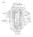
- FIG. 4 is a side view showing the main part of the transmission ratio variable mechanism 5 in cross section.
- the input member 20 and the output member 22 are shown as side surfaces, and the race ring unit 39 is shown as a cross section.
- the inner ring 391 of the bearing ring unit 39 includes a cylindrical first member 151, a cylindrical second member 152, and an annular inner ring main body 153.
- the first member 151, the second member 152, and the inner ring main body 153 are formed using different members from each other, and are coupled to rotate around the second axis B.
- the first member 151 is disposed adjacent to the input member 20 and includes a first tubular portion 154 and a first annular flange 155 provided at one end of the first tubular portion 154. is doing.
- the first annular flange 155 extends radially outward with respect to the first tubular portion 154.
- the first annular flange 155 includes a first end surface 71 and a first end surface 157 as a pair of end surfaces with respect to the axial direction S2 of the second axis B (hereinafter simply referred to as the axial direction S2).
- the other end surface facing the input member 20 is a first end surface 71 of the inner ring 391.
- the one end face 157 faces the first end face 71 in the axial direction S2.
- the one end surface 157 is in surface contact with the one end surface 153b of the inner ring main body 153 over the entire circumference.
- An inner side surface 158 facing the second member 152 is formed at the other end 154 a as an opposite end of the first tubular portion 154.
- the second member 152 is disposed adjacent to the output member 22 and has a second cylindrical portion 159 and a second annular flange 160 provided at one end of the second cylindrical portion 159. is doing.
- the second annular flange 160 extends radially outward with respect to the second cylindrical portion 159.
- the second annular flange 160 includes a second end surface 73 and one end surface 163 as a pair of end surfaces with respect to the axial direction S2. Of the pair of end surfaces of the second annular flange 160, the other end surface facing the output member 22 is a second end surface 73 of the inner ring 391. Of the pair of end surfaces of the second annular flange 160, the one end surface 163 faces the second end surface 73 in the axial direction S1.
- the one end surface 163 is in surface contact with the other end surface 153c of the inner ring main body 153 over the entire circumference.
- An inner side surface 164 that faces the first member 151 is formed at the other end 159 a as the opposite end of the second tubular portion 159.
- the other end 159a of the second tubular portion 159 and the other end 154a of the first tubular portion 154 are opposed to each other in the axial direction S2.
- the first and second cylindrical portions 154 and 159 include a restricting structure 165 for restricting relative rotation of the inner ring 391 in the circumferential direction C1 (hereinafter simply referred to as the circumferential direction C1).
- the restricting structure 165 includes a first undulating portion 166 formed on the inner side surface 158 of the first cylindrical portion 154, and a second undulating portion 167 provided on the inner side surface 164 of the second cylindrical portion 159. Is included.
- the first and second undulating portions 166, 167 are formed on the entire inner circumference along the circumferential direction C1 on the corresponding inner side surfaces 158, 164. These first and second undulating portions 166 and 167 have a waveform shape.
- each of the first and second undulating portions 166 and 167 has a rectangular wave shape.
- the first and second undulating portions 166 and 167 are engaged with each other in a concave-convex manner, and are in contact with each other with no gap in the circumferential direction C1.
- each of the other end portions 154a and 159a has the first tubular portion 154 (second tubular portion). 159) in a rectangular wave shape extending in the circumferential direction C3.
- the shapes of the edges of the other end portions 154a and 159a are the same.
- the fitting convex part 201 is formed in the other end part 154a of the first cylindrical part 154.
- a fitting recess 202 is formed at the other end 159 a of the second cylindrical portion 159.
- the fitting convex portion 201 and the fitting concave portion 202 are each formed in a rectangular wave shape extending in the circumferential direction C3.
- the relative rotation of the first and second members 151 and 152 in the circumferential direction C3 is restricted.
- An inner ring raceway 168 is formed on the outer peripheral surface 153 a of the inner ring main body 153.
- the inner ring raceway 168 is a raceway surface through which the rolling elements 393 pass, and has an arcuate cross section.
- the inner ring main body 153 is fixed to the first and second members 151 and 152. Specifically, one end surface 153 b of the inner ring main body 153 is along the first annular flange 155 and is in surface contact with the one end surface 157 of the first annular flange 155. Further, the other end surface 153 c of the inner ring main body 153 is along the second annular flange 160 and is in surface contact with the one end surface 163 of the second annular flange 160.
- the inner peripheral surface 153d of the inner ring main body 153 is press-fitted and fixed to the outer peripheral surfaces 171 and 172 of the first and second cylindrical portions 154 and 159, respectively.
- a first press-fit portion 173 and a first relief recess 174 are provided on the outer peripheral surface 171 of the first cylindrical portion 154.
- a second press-fit portion 175 and a second relief recess 176 are provided on the outer peripheral surface 172 of the second cylindrical portion 159.
- the first press-fit portion 173 is disposed at a position relatively far from the second member 152, and the first relief recess 174 is at a position relatively close to the second member 152.
- the first press-fit portion 173 has a relatively large diameter, and is press-fitted and fixed to the inner peripheral surface 153 d of the inner ring main body 153. Since the first relief recess 174 is formed to have a relatively small diameter, a gap D is formed between the inner ring main body 153 and the inner peripheral surface 153d, and is not in contact with the inner peripheral surface 153d. . That is, the first relief recess 174 is recessed with respect to the first press-fit portion 173.
- the second press-fit portion 175 is disposed at a position relatively far from the first member 151, and the second relief recess 176 is at a position relatively close to the first member 151.
- the second press-fit portion 175 has a relatively large diameter, and is press-fitted and fixed to the inner peripheral surface 153 d of the inner ring main body 153. Since the second relief recess 176 is formed to have a relatively small diameter, a gap D is formed with the inner peripheral surface 153d of the inner ring main body 153, and is not in contact with the inner peripheral surface 153d. . That is, the second relief recess 176 is recessed with respect to the second press-fit portion 175.
- the first and second relief recesses 174 and 176 are adjacent to each other in the axial direction S2, and the gap D is formed by the first and second relief recesses 174 and 176.
- the positions of the first and second relief recesses 174, 176 are associated with the position of the inner ring raceway 168.
- the length of the inner ring raceway 168 and the lengths of the first and second relief recesses 174, 176 are equal to each other.
- the inner ring raceway 168 and the first and second relief recesses 174, 176 are substantially aligned at one end and are aligned at the other end. Yes.
- first and second relief recesses 174 and 176 are arranged adjacent to each other between the first and second press-fit portions 173 and 175 with respect to the axial direction S2. Further, with respect to the radial direction R3 of the inner ring 391, the inner ring raceway 168 and the first and second relief recesses 174 and 176 are opposed to each other.
- a first uneven engagement portion 64 is provided on the input member main body 201 and the first member 151 of the inner ring 391. As a result, the input member 20 and the inner ring 391 can transmit power.
- a second uneven engagement portion 67 is provided on the second member 152 and the output member 22 of the inner ring 391. As a result, the inner ring 391 and the output member 22 can transmit power.
- the first concave / convex engaging portion 64 is formed on the first convex portion 65 formed on the power transmission surface 70 as one end surface of the input member main body 201 and the first end surface 71 of the inner ring 391.
- a first recess 66 that engages with the portion 65.
- the first convex portion 65 and the first concave portion 66 are formed on the corresponding power transmission surface 70 and the first end surface 71 over the entire area in the respective circumferential directions.
- Each first convex portion 65 has, for example, a semicircular cross section.
- Each first concave portion 66 has a shape that substantially matches the first convex portion 65.
- the power transmission surface 70 and the first end surface 71 are opposed to each other in the axial direction S of the steering shaft 3 (hereinafter simply referred to as the axial direction S). And the 1st end surface 71 is engaged so that power transmission is possible.
- 38 first protrusions 65 are formed.
- the number of first recesses 66 is different from the number of first protrusions 65.
- differential rotation can be generated between the input member main body 201 and the inner ring 391.
- the arrangement of the first convex portion 65 and the arrangement of the first concave portion 66 may be interchanged.
- the first convex portion 65 is formed on the first end surface 71 of the inner ring 391
- the first concave portion 66 is formed on the power transmission surface 70 of the input member 20.
- the second uneven engagement portion 67 includes a second convex portion 68 formed on the power transmission surface 72 as one end surface of the output member 22, and a second end surface 73 of the inner ring 391.
- a second concave portion 69 that engages with the second convex portion 68.
- the power transmission surface 72 and the second end surface 73 are opposed to each other with respect to the axial direction S, and the second concavo-convex engaging portion 67 engages the power transmission surface 72 and the second end surface 73 so that power can be transmitted.
- the second convex portion 68 of the second concave-convex engaging portion 67 has the same configuration as the first convex portion 65 of the first concave-convex engaging portion 64, and the second concave portion 69 is 1 has the same configuration as that of the first recess 66. More specifically, the power transmission surface 72 of the output member 22 has the same configuration as the power transmission surface 70 of the input member main body 201, and the second end surface 73 of the inner ring 391 is the second end surface 73 of the inner ring 391. 1 has the same configuration as the end face 71 of the first. Therefore, the detailed description of the second uneven engagement portion 67 is omitted.
- the second axis B of the inner ring 391 is inclined by a predetermined angle ⁇ with respect to the first axis A of the input member 20 and the output member 22, some of the first convex portions 65 and some of the The first recess 66 meshes with each other. Further, some of the second convex portions 68 and some of the second concave portions 69 are engaged with each other.
- a bevel gear is formed on each of the power transmission surface 70 of the input member main body 201 and the first end surface 71 of the inner ring 391 to form a first concave and convex engaging portion, and the second end surface 73 of the inner ring 391 and You may comprise a 2nd uneven
- the first convex portion and the second convex portion are each configured by teeth of the bevel gear, and the first concave portion and the second concave portion are grooves between the teeth of the bevel gear, respectively. Consists of.
- the rotor 231 of the transmission ratio variable mechanism motor 23 includes a cylindrical rotor core 85 extending in the axial direction S, and a permanent magnet 86 fixed to the outer peripheral surface of the rotor core 85.
- a torque sensor 44 is accommodated in the rotor core 85.
- the rotor core 85 surrounds both the first concavo-convex engaging portion 64 and the second concavo-convex engaging portion 67 over the entire circumference, and the torque sensor 44 is surrounded over the entire circumference.
- the length of the housing 24 in the axial direction S can be shortened.
- a retained hole 87 for the second bearing 32 is formed at one end of the rotor core 85.
- An annular bearing holding portion 88 is provided inside the held hole 87 in the radial direction.
- the bearing holding portion 88 is disposed on an annular convex portion 89 formed at one end of the first housing 51.
- the second bearing 32 is interposed between the held hole 87 and the bearing holding portion 88. As a result, one end of the rotor core 85 is rotatably supported by the first housing 51.
- a retained hole 90 for the fourth bearing 34 is formed in an intermediate portion of the rotor core 85.
- An annular bearing holding portion 91 is provided inside the held hole 90 in the radial direction.
- the bearing holding portion 91 is disposed in an annular extending portion 92 formed at one end of the second housing 52.
- the annular extending portion 92 has a cylindrical shape extending from the partition wall portion 93 provided at the other end of the second housing 52 to the one side S ⁇ b> 1 in the axial direction S, and is inserted through the rotor core 85.
- the fourth bearing 34 is interposed between the held hole 90 and the bearing holding portion 91. Thereby, the intermediate part of the rotor core 85 is rotatably supported by the annular extending part 92 of the second housing 52.
- the second and fourth bearings 32 and 34 are arranged with the bearing ring unit 39 sandwiched in the axial direction of the rotor 231.
- the rotor core 85 is supported at two locations in the axial direction S by the pair of bearings 32 and 34.
- the permanent magnet 86 of the rotor 231 has different magnetic poles alternately in the circumferential direction C2 of the steering shaft 3.
- the permanent magnet 86 has a configuration in which N poles and S poles are alternately arranged at equal intervals in the circumferential direction C2.
- the permanent magnet 86 is fixed to the outer peripheral surface of the intermediate portion of the rotor core 85. The positions of the permanent magnet 86 and a part of the transmission ratio variable mechanism 5 in the axial direction S are overlapped with each other.
- the stator 232 of the transmission ratio variable mechanism motor 23 is accommodated in the first housing 51.
- the stator 232 includes a stator core 95 formed by laminating a plurality of electromagnetic steel plates and an electromagnetic coil 96.
- the stator core 232 includes an annular yoke 97 and a plurality of teeth 98 arranged at equal intervals in the circumferential direction of the yoke 97 and projecting radially inward of the yoke 97.
- the outer peripheral surface of the yoke 97 is fixed to the inner peripheral surface of the first housing 51 by shrinkage fit or the like.
- An electromagnetic coil 96 is wound around each tooth 98.
- the bus bar 99 is arranged on the other side S2 in the axial direction S with respect to the stator 232.
- the bus bar 99 is accommodated in the second housing 52 in an annular state as a whole, and is connected to each electromagnetic coil 96 of the transmission ratio variable mechanism motor 23.
- the bus bar 99 supplies power from the drive circuit to each electromagnetic coil 96.
- the positions of the bus bar 99 and the third and fourth bearings 33 and 34 with respect to the axial direction S are overlapped.
- a lock mechanism 58 is disposed on the other side S ⁇ b> 2 in the axial direction S with respect to the bus bar 99.
- the lock mechanism 58 is for restricting the rotation of the rotor 231 of the transmission ratio variable mechanism motor 23 and is housed in one end of the second housing 52.
- the lock mechanism 58 includes a regulated portion 100 that can rotate with the rotor core 85 and a regulating portion 101 that regulates rotation of the regulated portion 100 by engaging with the regulated portion 100.
- the regulated portion 100 is an annular member.
- a recess 102 is formed on the outer peripheral surface of the regulated portion 100. The recess 102 is formed at one or a plurality of locations in the circumferential direction of the regulated portion 100.
- the rotor core 85 may be provided with the recess 102 directly. In this case, the rotor core 85 constitutes the restricted portion.
- the part of the regulated part 100 is overlapped with the part of the torque sensor 44 at the position in the axial direction S.
- the restricting portion 101 is disposed radially outward of the restricted portion 100.
- the restricting portion 101 is held by the second housing 52 and can be moved to the restricted portion 100 side.
- a motor resolver 43 is arranged on the other side S ⁇ b> 2 in the axial direction S with respect to the lock mechanism 58.
- the motor resolver 43 is accommodated in the second housing 52 and is located radially outward of the rotor core 85.
- the position of the motor resolver 43 and the torque sensor 44 are overlapped with each other in the axial direction S.
- the motor resolver 43 includes a resolver rotor 105 and a resolver stator 106.
- the resolver rotor 105 is fixed to the outer peripheral surface of the other end of the rotor core 85 so as to be able to rotate together.
- the resolver stator 106 is fixed to the second housing 52.
- the first shaft 11 is rotatably supported by the first housing 51 via the cylindrical member 202 of the input member 20 and the first bearing 31.
- the first bearing 31 is surrounded by the second bearing 32, and their positions are aligned with respect to the axial direction S.
- the third bearing 33 is interposed between the bearing holding hole 110 and the bearing holding portion 111.
- the bearing holding hole 110 is formed in the inner peripheral portion at the tip of the extending portion 92 of the second housing 52.
- the bearing holding portion 111 is formed on the outer periphery of the output member 22.
- the output member 22 is rotatably supported by the annular extending portion 92 of the second housing 52 via the third bearing 33.
- the third bearing 33 is surrounded by the fourth bearing 34, and their positions are aligned with respect to the axial direction S.
- an elastic member 113 as an urging member is disposed on one end side of the first housing 51.
- the elastic member 113 is formed using a disc spring, for example.
- the elastic member 113 biases the input member main body 201 in a biasing direction H1 (the other side S2 in the axial direction S) as a direction in which the input member main body 201 approaches the output member 22.
- the elastic member 113 may be a wave washer formed in a corrugated shape, or may be another elastic body such as a resin ring.
- the elastic member 113 biases the input member main body 201 toward the output member 22. Thereby, a preload is applied to each of the first concave and convex engaging portion 64 and the second concave and convex engaging portion 67.
- the elastic member 113 is held in the bearing holding hole 134.
- the bearing holding hole 134 is formed on the inner periphery of the annular convex portion 89 at one end of the first housing 51.
- the elastic member 113 urges (presses) one end surface of the outer ring 312 of the first bearing 31 held in the bearing holding hole 134 toward the urging direction H1.
- the outer ring 312 of the first bearing 31 is fitted to the bearing holding hole 134 so as to be relatively movable in the axial direction S.
- a lid member 135 is provided adjacent to the elastic member 113.
- the lid member 135 is screwed into a female screw part 134 a formed in the bearing holding hole 134.
- the lid member 135 receives the elastic member 113 and restricts the urging member 113 from moving in the direction H2 opposite to the urging direction H1.
- the inner ring 311 of the first bearing 31 is press-fitted and fixed to one end of the cylindrical member 202, and the cylindrical member 202 and the input member main body 201 can rotate together and move in the axial direction S.
- the inner ring 311 urges the input member main body 201 in the urging direction H ⁇ b> 1 under the urging force of the elastic member 113.
- the first convex portion 65 of the first concave-convex engaging portion 64 faces the first concave portion 66 in the urging direction H1.
- corrugated engaging part 67 is facing the 2nd convex part 68 in the urging
- An inner ring 331 of a third bearing 33 is press-fitted and fixed to the output member 22.
- the outer ring 332 of the third bearing 33 is fitted in the bearing holding hole 110 and is movable relative to the bearing holding hole 110 in the axial direction S.
- the outer ring 332 of the third bearing 33 is received by an annular step 114 disposed adjacent to the bearing holding hole 110, and movement in the urging direction H1 is restricted.
- the urging force transmitted to the input member 20 is transmitted in the order of the first concavo-convex engaging portion 64, the second concavo-convex engaging portion 67, and the output member 22, and further the inner ring 331, rolling elements and outer ring 332 of the third bearing 33. It is transmitted to.
- the urging force transmitted to the outer ring 332 of the third bearing 33 is received by the annular step portion 114.
- the rolling elements 393, the outer ring 392 of the track ring unit 39 and the rotor 231 of the transmission ratio variable mechanism motor 23 are It moves together in the direction S.
- the outer ring 392 of the track ring unit 39 is press-fitted and fixed in the inclined hole 63 of the rotor core 85.
- the outer rings 322 and 342 of the second bearing 32 and the fourth bearing 34 are fitted into the corresponding annular held holes 87 and 90 of the rotor core 85 so that the rotor core 85 is relative to the axial direction S. Supports movable.
- the inner ring 321 of the second bearing 32 is press-fitted and fixed to the bearing holding portion 88 of the annular convex portion 89.
- the inner ring 341 of the fourth bearing 34 is press-fitted and fixed to the bearing holding portion 91 of the annular extending portion 92 of the second housing 52.
- the input member 20 and the output member 22 can be moved relative to the bearing ring unit 39 in the urging direction H1 and in the opposite direction H2 (axial direction S).
- the upper limit of the amount by which the input member 20 and the output member 22 can move in the axial direction S with respect to the housing 24 is restricted.
- the tip surface 89 a of the annular convex portion 89 of the first housing 51 is opposed to the annular surface 201 a of the input member main body 201 in the axial direction S.
- the tip end surface 92 a of the annular extending portion 92 of the second housing 24 is opposed to the annular surface 22 b of the output member 22 in the axial direction S.
- a predetermined gap E ⁇ b> 1 is provided between the front end surface 89 a of the annular protrusion 89 and the annular surface 201 a of the input member main body 201 in the initial state at the time of factory shipment.
- a predetermined gap E ⁇ b> 2 is provided between the tip end surface 92 a of the annular extending portion 92 and the annular surface 22 b of the output member 22.
- the first convex portion 65 and the first concave portion 66 in the first concave / convex engaging portion 64 can be maintained in a positively engaged state, so that the first convex portion 65 and the first concave portion 66 can be maintained. It is possible to prevent tooth skipping (slipping) between them.
- the second convex portion 68 and the second concave portion 69 in the second concave-convex engaging portion 67 can be maintained in a reliable engagement state, the second convex portion 68 and the second concave portion 69 can be maintained. It is possible to prevent tooth skipping (slipping).
- the elastic member 113 may be used to bias the output member 22 in a direction in which the output member 22 approaches the input member 20 (a direction H2 opposite to the biasing direction H1).
- the elastic member 113 is held in the bearing holding hole 110 that holds the third bearing 33 and is sandwiched between the annular stepped portion 114 and the outer ring 332 of the third bearing 33.
- the urging force of the elastic member 113 includes the third bearing 33, the output member 22, the second uneven engagement portion 67, the first uneven engagement portion 64, the input member 20, the inner ring 311 of the first bearing 31, the rolling force.
- the moving body, the outer ring 312 and the lid member 135 are transmitted in this order and are received by the first housing 51.
- the preload is applied to each of the first and second concave and convex engaging portions 64 and 67 using the elastic member 113.
- a constant pressure preload structure as a structure capable of making the preload to the first and second concave and convex engaging portions 64 and 67 substantially constant. Therefore, preload management at the time of manufacture can be facilitated.
- a structure that can regulate the amount of movement of the input member 20 and the output member 22 in the axial direction S relative to the inner ring 391 is employed.
- the support mechanism 133 does not prevent the displacement of the inner ring 391 in the axial direction S.
- the outer ring 382 of the eighth bearing 38 of the support mechanism 133 is fitted into the bearing holding hole 109 of the cylindrical member 202 and is movable in the axial direction S with respect to the bearing holding hole 109.
- the inner ring 381 of the eighth bearing 38 is press-fitted and fixed to the opposed end portion 12 a of the second shaft 12.
- the outer ring 382 of the eighth bearing 38 may be press-fitted and fixed in the bearing holding hole 109, and the inner ring 381 may be loosely fitted to the opposed end portion 12a.
- the torque sensor 44 is disposed radially inward of the rotor core 85 of the transmission ratio variable mechanism motor 23.
- the torque sensor 44 includes a multipolar magnet 115 fixed to an intermediate portion of the second shaft 12 and magnetic yokes 116 and 117 supported on one end of the third shaft 13.
- the magnetic yokes 116 and 117 are a pair of soft magnetic bodies that are arranged in a magnetic field generated by the multipolar magnet 115 to form a magnetic circuit.
- the multipolar magnet 115 is a cylindrical permanent magnet, and a plurality of poles (the same number of N and S respectively) are magnetized at equal intervals in the circumferential direction.
- the magnetic yokes 116 and 117 surround the multipolar magnet 115.
- Each of the magnetic yokes 116 and 117 is molded on a synthetic resin member 118.
- the synthetic resin member 118 is coupled to one end of the third shaft 13 so as to be able to rotate together.
- the torque sensor 44 further includes a pair of magnetism collecting rings 119 and 120 for inducing magnetic flux from the magnetic yokes 116 and 117.
- the pair of magnetism collecting rings 119 and 120 are annular members formed using a soft magnetic material.
- the pair of magnetism collecting rings 119 and 120 surround the magnetic yokes 116 and 117 and are magnetically coupled to the magnetic yokes 116 and 117, respectively.
- the pair of magnetism collecting rings 119 and 120 are separated from each other in the axial direction S and face each other.
- the magnetism collecting rings 119 and 120 are molded by the synthetic resin member 121.
- the synthetic resin member 121 is held by the annular extending portion 92 of the second housing 52.
- Magnetic flux is generated in the magnetic yokes 116 and 117 in accordance with the relative rotational amounts of the second and third shafts 12 and 13.
- This magnetic flux is induced by the magnetic flux collecting rings 119 and 120 and detected by a Hall IC (not shown) embedded in the synthetic resin member 121. Thereby, the magnetic flux density according to the torque applied to the second shaft 12 can be detected.
- a fifth bearing 35 is arranged on the other side S ⁇ b> 2 in the axial direction S with respect to the torque sensor 44.
- the fifth bearing 35 is interposed between a bearing holding portion 122 formed on the outer periphery of one end of the third shaft 13 and a bearing holding hole 123 formed in the partition wall portion 93 of the second housing 52. Yes.
- the bearing holding hole 123 rotatably supports one end of the third shaft 13 through the fifth bearing 35.
- the third shaft 13 surrounds the second shaft 12 and the torsion bar 14. Specifically, an insertion hole 124 opened at one end of the third shaft 13 is formed in the third shaft 13. The other end of the second shaft 12 is inserted through the insertion hole 124. An insertion hole 125 extending in the axial direction S is formed in the second shaft 12, and the torsion bar 14 is inserted through the insertion hole 125.
- One end of the torsion bar 14 is connected to one end of the insertion hole 125 of the second shaft 12 so as to be able to rotate together by serration fitting or the like.
- the other end of the torsion bar 14 is connected to the insertion hole 124 of the third shaft 13 by serration fitting or the like so as to be able to rotate together.
- a space in the radial direction of the annular extending portion 92 of the second housing 52 serves as a torque sensor housing chamber 126.
- a structure for suppressing the intrusion of the lubricant into the torque sensor housing chamber 126 is further provided.
- a third bearing 33 with a seal disposed at one end of the annular extending portion 92 of the second housing 52, and an output member 22 disposed radially inward of the third bearing 33
- One end of the torque sensor housing chamber 126 is closed by the second shaft 12 disposed radially inward of the output member 22.
- the second shaft 12 and the third shaft 13 are relatively rotatable via a sixth bearing 36.
- the sixth bearing 36 is surrounded by the worm wheel 28 of the speed reduction mechanism 26.
- the speed reduction mechanism 26 is accommodated in the accommodation chamber 128.
- the storage chamber 128 is partitioned by the outer peripheral portion 127 of the third housing 53, the end wall portion 61, and the partition wall portion 93 of the second housing 52. A part of the worm wheel 28 and the sixth bearing 36 overlap with each other in the position in the axial direction S.
- a seventh bearing 37 is interposed between the intermediate portion of the third shaft 13 and the end wall portion 61 of the third housing 53.
- the end wall portion 61 supports the third shaft 13 via the seventh bearing 37 so as to be rotatable.
- the inner ring 371 of the seventh bearing 37 is sandwiched between an annular step 129 formed on the outer peripheral portion of the third shaft 13 and a nut member 130 screwed to the outer peripheral portion of the third shaft 13. Yes.
- the outer ring 372 of the seventh bearing 37 is sandwiched between an annular step 131 formed in the third housing 53 and a retaining ring 132 held by the third housing 53.
- the first and second members 151 and 152 of the inner ring 391 of the track ring unit 39 are formed separately from each other and are coupled to each other so as to be able to move together.
- the corresponding recesses 66 and 69 can be formed in the first and second end faces 71 and 73 of the inner ring 391 with less labor as follows, for example. .
- the first recess 66 is formed in one end surface (corresponding to the first end surface 71) of the manufacturing intermediate of the first member 151, and separately from this, one end surface of the manufacturing intermediate of the second member 152
- the second recess 69 can be formed on the first and second end surfaces 71, 73.
- the following laborious work is required. It is. That is, after forming a recess on one end surface, a laborious operation is required in which the recess is formed on the other end surface in a state where the recess is positioned with respect to the recess on the one end surface.
- the first and second members 151 and 152 can be formed separately, the above laborious work is unnecessary.
- the first and second members 151 and 152 may be combined.
- the inner ring raceway 168 can be formed by cutting the intermediate product of the inner ring main body 153 in a single product state.
- the inner ring in addition to forming recesses on a pair of end faces of an inner ring manufacturing intermediate made of a single member, the inner ring is formed by forming an inner ring raceway. It is not necessary to set the relative position of each other with high accuracy when forming 66 and 69, and the labor for manufacturing the inner ring 391 can be reduced.
- the inner ring main body 153 for example, a bearing inner ring of a standard size defined by a standard such as JIS (Japanese Industrial Standard) can be used, and the inner ring main body 153 can be formed at a lower cost.
- the inner ring main body 153 is sandwiched between the first annular flange 155 of the first member 151 and the second annular flange 160 of the second member 152.
- wheel main body 153 and the 1st and 2nd members 151 and 152 can be made higher.
- the one end surfaces 157 and 163 of the annular flanges 155 and 160 are along the corresponding end surfaces 153b and 153c of the inner ring main body 153, and the annular flanges 155 and 160
- the other end surfaces are the corresponding first and second end surfaces 71 and 73.
- the thrust force that acts on the first end surface 71 of the inner ring 391 from the input member 20 and the thrust force that acts on the second end surface 73 of the inner ring 391 from the output member 22 result in the annular flanges 155 and 160 as a whole.
- the inner ring main body 153 is tightened. Thereby, the mutual coupling force of the 1st and 2nd members 151 and 152 and the inner ring main body 153 can be raised more.
- first and second relief recesses 174 and 176 are provided. Thereby, the fluctuation
- the first and second relief recesses 174 and 176 are sandwiched between the first and second press-fit portions 173 and 175.
- the inner ring raceway 168 and the first and second relief recesses 174 and 176 It is opposed to the radial direction R3 of 391.
- the other end portions 154a, 159a (opposing end portions) of the first and second cylindrical portions 154, 159 are circumferential directions C3 of the cylindrical portions 154, 159 when viewed along the radial direction R2. It is formed in a rectangular wave shape extending in the direction.
- the inner ring 391 can be rotated around the first axis A by rotating the outer ring 392 of the raceway ring unit 39 around the first axis A by the transmission ratio variable mechanism motor 23.
- the inner ring 391 can perform Coriolis motion (swing motion).
- a first uneven engagement portion 64 and a second uneven engagement portion 67 are provided on both sides of the inner ring 391.
- the opposed end portions 11a and 12a of the first and second shafts 11 and 12 are supported by a support mechanism 133 so as to be relatively rotatable.
- the runout of the opposing end portions 11a and 12a of the first and second shafts 11 and 12 can be further reduced.
- the eccentric rotation of the input member 20 and the output member 22 with respect to the first axis A can be further reduced.
- the first member 151 and the second member 152 of the inner ring 391 are changed from the input member 20 and the output member 22 to each other. It can suppress more reliably that an excessive force acts. As a result, it is possible to more reliably prevent the relative positions of the first and second members 151 and 152 from shifting.
- the input member 20 supports the first shaft 11 and supports the opposing end portion 12 a of the second shaft 12 via the eighth bearing 38.
- the support mechanism 133 can be realized at low cost. Further, the eccentric rotation of the opposed end portions 11a and 12a of the shafts 11 and 12 with respect to the first axis A can be more reliably reduced.
- a steering assist force applying mechanism 19 is provided in addition to the transmission ratio variable mechanism 5.
- the transmission ratio variable mechanism motor 23 can be reduced in cost and size.
- the steering assist force generated by the steering assist motor 25 is transmitted to the steered wheels 4L and 4R via the third shaft 13 and the like, so that the steered wheels 4L are not transmitted via the transmission ratio variable mechanism 5. , Transmitted to 4R. Therefore, the large torque from the steering assist motor 25 can be prevented from being transmitted to the transmission ratio variable mechanism 5, so that the allowable torque of each component of the transmission ratio variable mechanism 5 can be further reduced.
- each component of the transmission ratio variable mechanism 5 can be further reduced.
- the torque acting between the first and second members 151 and 152 of the inner ring 391 can be small, and the relative position of these members 151 and 152 can be more reliably suppressed.
- the biasing force by the elastic member 113 can be adjusted by adjusting the screwing amount of the lid member 135 into the female screw part 134a. Further, the urging force of the elastic member 113 can be transmitted to the inner ring 311 of the first bearing 31 via the outer ring 312 of the first bearing 31, and preload can be reliably applied to the first bearing 31. .
- the second and fourth bearings 32 and 34 support the rotor 231 so as to be movable in the axial direction S.
- the inner ring 391 moves in the axial direction of the rotor 231
- the outer ring 392 and the rotor 231 can move in the axial direction of the rotor 231.
- unnecessary force is generated between the inner ring 391 and the outer ring 392. It can prevent acting.
- first and second undulating portions 166 and 167 having a triangular wave shape may be used.
- first cylindrical portion 154A second cylindrical portion 159A
- each of the other end portions 154aA and 159aA corresponds to the first cylindrical portion 154A (second cylindrical portion).
- 159A) is formed in a triangular wave shape extending in the circumferential direction C3.
- the fitting convex portion 201A is formed on the other end portion 154aA of the first cylindrical portion 154A
- the fitting concave portion 202A is formed on the other end portion 159aA of the second cylindrical portion 159A. Yes.
- the fitting convex portion 201A and the fitting concave portion 202A are each formed in a triangular wave shape extending in the circumferential direction C3.
- the relative rotation of the first and second members 151A, 152A in the circumferential direction C3 is restricted.
- the relative rotation of the first and second members 151A and 152A can be reliably restricted by the fitting of the triangular wave-shaped fitting concave portion 202A and the fitting convex portion 201A.
- the inner ring of the track ring unit is rotationally driven by the transmission ratio variable mechanism motor, the outer ring and the input member are connected by the first uneven engagement portion, and the outer ring and the output member are further connected by the second uneven engagement member.
- the outer ring is the first race ring, and the inner ring is the second race ring.
- the outer ring includes a first member formed with a first end face, a second member formed with a second end face, and an outer ring main body fixed to the first and second members. It becomes the composition containing.
- SYMBOLS 1 Vehicle steering device, 2 ... Steering member, 4L, 4R ... Steering wheel, 5 ... Transmission ratio variable mechanism, 11 ... 1st shaft, 11a ... Opposing end part, 12 ... 2nd shaft, 12a ... Opposing end 13, a third shaft (a shaft interposed between the output member and the steered wheel), 19, a steering assist force applying mechanism, 20, an input member, 22, an output member, 23, a transmission ratio variable mechanism motor ( Actuator), 25 ... Steering assist motor (second actuator), 26 ... Deceleration mechanism (transmission mechanism), 38 ... Eighth bearing (bearing of support mechanism), 64 ... First uneven engagement portion, 65 ... 1st convex part, 66 ...
- first cylindrical part, 154a, 154aA opposite end part of first cylindrical part
- other end part 155 ... first annular flange, 157 ... one end surface (of the annular flange), 159 ... second cylindrical part, 159a, 159aA ... (opposite end part of the second cylindrical part) the other end part, 160 ... second annular flange, 163 ... ( One end surface (of the annular flange), 168 ... inner ring raceway, 171 ... outer periphery (of the first cylindrical portion), 172 ... outer periphery of (the second cylindrical portion), 173 ... first press-fit portion, 174 ...
Landscapes
- Engineering & Computer Science (AREA)
- General Engineering & Computer Science (AREA)
- Mechanical Engineering (AREA)
- Chemical & Material Sciences (AREA)
- Combustion & Propulsion (AREA)
- Transportation (AREA)
- Power Steering Mechanism (AREA)
- Steering Control In Accordance With Driving Conditions (AREA)
- Retarders (AREA)
Priority Applications (2)
| Application Number | Priority Date | Filing Date | Title |
|---|---|---|---|
| EP09773170.7A EP2298623B1 (en) | 2008-06-30 | 2009-06-30 | Transmission ratio changing mechanism and vehicle steering device |
| US13/000,484 US8245814B2 (en) | 2008-06-30 | 2009-06-30 | Transmission ratio variable mechanism and vehicle steering apparatus |
Applications Claiming Priority (2)
| Application Number | Priority Date | Filing Date | Title |
|---|---|---|---|
| JP2008171450A JP5229543B2 (ja) | 2008-06-30 | 2008-06-30 | 車両用操舵装置 |
| JP2008-171450 | 2008-06-30 |
Publications (1)
| Publication Number | Publication Date |
|---|---|
| WO2010001592A1 true WO2010001592A1 (ja) | 2010-01-07 |
Family
ID=41465699
Family Applications (1)
| Application Number | Title | Priority Date | Filing Date |
|---|---|---|---|
| PCT/JP2009/003026 Ceased WO2010001592A1 (ja) | 2008-06-30 | 2009-06-30 | 伝達比可変機構および車両用操舵装置 |
Country Status (4)
| Country | Link |
|---|---|
| US (1) | US8245814B2 (enExample) |
| EP (1) | EP2298623B1 (enExample) |
| JP (1) | JP5229543B2 (enExample) |
| WO (1) | WO2010001592A1 (enExample) |
Cited By (2)
| Publication number | Priority date | Publication date | Assignee | Title |
|---|---|---|---|---|
| EP2743235A1 (en) | 2012-12-13 | 2014-06-18 | Fulvio Antonio De Asmundis | Method and apparatus for treating sewage |
| EP2743234A1 (en) | 2012-12-13 | 2014-06-18 | Fulvio Antonio De Asmundis | Method and apparatus for treating sewage |
Families Citing this family (6)
| Publication number | Priority date | Publication date | Assignee | Title |
|---|---|---|---|---|
| JP5282938B2 (ja) * | 2008-07-07 | 2013-09-04 | 株式会社ジェイテクト | 伝達比可変機構およびこれを備える車両用操舵装置 |
| DE102012215775A1 (de) * | 2012-09-06 | 2014-03-06 | Zf Friedrichshafen Ag | Stellgetriebe |
| EP2913245B1 (en) * | 2012-10-29 | 2019-03-27 | NSK Ltd. | Electric power-steering device |
| JP2015142454A (ja) * | 2014-01-29 | 2015-08-03 | キヤノン株式会社 | アクチュエータ及び多関節ロボットアーム |
| CN105757184B (zh) * | 2016-03-31 | 2018-10-16 | 朱清泉 | 一种减速器及搅拌机和搅拌运输罐车 |
| CN115978165A (zh) * | 2022-12-05 | 2023-04-18 | 浙江夏厦精密制造股份有限公司 | 一种带二级减速的减速装置 |
Citations (9)
| Publication number | Priority date | Publication date | Assignee | Title |
|---|---|---|---|---|
| JPS6011749A (ja) * | 1983-06-30 | 1985-01-22 | Sanwa Tekki Corp | 断面円弧歯のフエ−スギア装置 |
| JPH10184819A (ja) | 1996-12-19 | 1998-07-14 | Namu:Kk | 変速歯車装置 |
| JP2006046405A (ja) * | 2004-08-02 | 2006-02-16 | Ogino Kogyo Kk | 変速歯車装置 |
| JP2006082718A (ja) | 2004-09-16 | 2006-03-30 | Toyoda Mach Works Ltd | 舵角比可変操舵装置 |
| JP2007170624A (ja) * | 2005-12-26 | 2007-07-05 | Toyota Motor Corp | 伝達比可変装置および車両操舵装置 |
| JP2007274931A (ja) * | 2006-04-04 | 2007-10-25 | Fuji Kogyo Co Ltd | 釣竿用導糸環 |
| JP2007302197A (ja) | 2006-05-15 | 2007-11-22 | Jtekt Corp | 車両用操舵装置 |
| JP2008030747A (ja) * | 2007-09-11 | 2008-02-14 | Ogino Kogyo Kk | ステアリング装置 |
| JP2008171450A (ja) | 2008-03-25 | 2008-07-24 | Max Co Ltd | タイムレコーダ |
Family Cites Families (7)
| Publication number | Priority date | Publication date | Assignee | Title |
|---|---|---|---|---|
| ZA738845B (en) * | 1972-12-27 | 1974-10-30 | R Davidson | Speed and/or direction change means |
| US3935750A (en) * | 1973-10-23 | 1976-02-03 | Maroth Arthur M | Counterbalanced mechanical speed-change mechanism |
| IT1156995B (it) * | 1978-04-28 | 1987-02-04 | Roltra Spa | Dispositivo di regolazione della posizione angolare relativa di due elementi |
| DE19839720C1 (de) * | 1998-09-01 | 1999-11-25 | Gkn Viscodrive Gmbh | Drehmoment-abhängig reagierendes Sperrdifferential mit wenigen Teilen |
| EP1857347B1 (en) * | 2006-05-15 | 2009-08-19 | JTEKT Corporation | Steering apparatus for vehicle |
| JP5234314B2 (ja) * | 2007-10-22 | 2013-07-10 | 株式会社ジェイテクト | 車両用操舵装置 |
| JP4940122B2 (ja) * | 2007-12-21 | 2012-05-30 | 株式会社日立製作所 | ハードディスクメディア上のパターンの検査方法及び検査装置 |
-
2008
- 2008-06-30 JP JP2008171450A patent/JP5229543B2/ja not_active Expired - Fee Related
-
2009
- 2009-06-30 US US13/000,484 patent/US8245814B2/en not_active Expired - Fee Related
- 2009-06-30 WO PCT/JP2009/003026 patent/WO2010001592A1/ja not_active Ceased
- 2009-06-30 EP EP09773170.7A patent/EP2298623B1/en not_active Not-in-force
Patent Citations (9)
| Publication number | Priority date | Publication date | Assignee | Title |
|---|---|---|---|---|
| JPS6011749A (ja) * | 1983-06-30 | 1985-01-22 | Sanwa Tekki Corp | 断面円弧歯のフエ−スギア装置 |
| JPH10184819A (ja) | 1996-12-19 | 1998-07-14 | Namu:Kk | 変速歯車装置 |
| JP2006046405A (ja) * | 2004-08-02 | 2006-02-16 | Ogino Kogyo Kk | 変速歯車装置 |
| JP2006082718A (ja) | 2004-09-16 | 2006-03-30 | Toyoda Mach Works Ltd | 舵角比可変操舵装置 |
| JP2007170624A (ja) * | 2005-12-26 | 2007-07-05 | Toyota Motor Corp | 伝達比可変装置および車両操舵装置 |
| JP2007274931A (ja) * | 2006-04-04 | 2007-10-25 | Fuji Kogyo Co Ltd | 釣竿用導糸環 |
| JP2007302197A (ja) | 2006-05-15 | 2007-11-22 | Jtekt Corp | 車両用操舵装置 |
| JP2008030747A (ja) * | 2007-09-11 | 2008-02-14 | Ogino Kogyo Kk | ステアリング装置 |
| JP2008171450A (ja) | 2008-03-25 | 2008-07-24 | Max Co Ltd | タイムレコーダ |
Non-Patent Citations (1)
| Title |
|---|
| See also references of EP2298623A4 |
Cited By (2)
| Publication number | Priority date | Publication date | Assignee | Title |
|---|---|---|---|---|
| EP2743235A1 (en) | 2012-12-13 | 2014-06-18 | Fulvio Antonio De Asmundis | Method and apparatus for treating sewage |
| EP2743234A1 (en) | 2012-12-13 | 2014-06-18 | Fulvio Antonio De Asmundis | Method and apparatus for treating sewage |
Also Published As
| Publication number | Publication date |
|---|---|
| US8245814B2 (en) | 2012-08-21 |
| JP5229543B2 (ja) | 2013-07-03 |
| US20110108354A1 (en) | 2011-05-12 |
| EP2298623A4 (en) | 2012-10-17 |
| EP2298623A1 (en) | 2011-03-23 |
| EP2298623B1 (en) | 2014-04-23 |
| JP2010006349A (ja) | 2010-01-14 |
Similar Documents
| Publication | Publication Date | Title |
|---|---|---|
| JP5234314B2 (ja) | 車両用操舵装置 | |
| JP5282938B2 (ja) | 伝達比可変機構およびこれを備える車両用操舵装置 | |
| WO2010001592A1 (ja) | 伝達比可変機構および車両用操舵装置 | |
| CN101835672B (zh) | 传动比可变机构及具有该机构的车辆用操舵装置 | |
| CN103318253A (zh) | 车辆用转向操作装置 | |
| JP2009171736A (ja) | 電動モータ | |
| JP5218830B2 (ja) | 車両用操舵装置 | |
| JP5224109B2 (ja) | 車両用操舵装置 | |
| JP5234313B2 (ja) | 車両用操舵装置 | |
| JP5365833B2 (ja) | 車両用操舵装置 | |
| JP5472686B2 (ja) | 車両用操舵装置 | |
| JP5110361B2 (ja) | 伝達比可変機構およびこれを備える車両用操舵装置 | |
| JP5110362B2 (ja) | 伝達比可変機構およびこれを備える車両用操舵装置 | |
| JP5158419B2 (ja) | 車両用操舵装置 | |
| JP6443673B2 (ja) | ステアリング装置 | |
| JP2010006341A (ja) | 車両用操舵装置 | |
| JP2008201378A (ja) | 舵角可変式ステアリング装置 |
Legal Events
| Date | Code | Title | Description |
|---|---|---|---|
| 121 | Ep: the epo has been informed by wipo that ep was designated in this application |
Ref document number: 09773170 Country of ref document: EP Kind code of ref document: A1 |
|
| WWE | Wipo information: entry into national phase |
Ref document number: 13000484 Country of ref document: US |
|
| WWE | Wipo information: entry into national phase |
Ref document number: 2009773170 Country of ref document: EP |
|
| NENP | Non-entry into the national phase |
Ref country code: DE |