WO2010001592A1 - Transmission ratio changing mechanism and vehicle steering device - Google Patents
Transmission ratio changing mechanism and vehicle steering device Download PDFInfo
- Publication number
- WO2010001592A1 WO2010001592A1 PCT/JP2009/003026 JP2009003026W WO2010001592A1 WO 2010001592 A1 WO2010001592 A1 WO 2010001592A1 JP 2009003026 W JP2009003026 W JP 2009003026W WO 2010001592 A1 WO2010001592 A1 WO 2010001592A1
- Authority
- WO
- WIPO (PCT)
- Prior art keywords
- inner ring
- transmission ratio
- ratio variable
- variable mechanism
- shaft
- Prior art date
Links
Images


Classifications
-
- B—PERFORMING OPERATIONS; TRANSPORTING
- B62—LAND VEHICLES FOR TRAVELLING OTHERWISE THAN ON RAILS
- B62D—MOTOR VEHICLES; TRAILERS
- B62D5/00—Power-assisted or power-driven steering
- B62D5/008—Changing the transfer ratio between the steering wheel and the steering gear by variable supply of energy, e.g. by using a superposition gear
-
- F—MECHANICAL ENGINEERING; LIGHTING; HEATING; WEAPONS; BLASTING
- F16—ENGINEERING ELEMENTS AND UNITS; GENERAL MEASURES FOR PRODUCING AND MAINTAINING EFFECTIVE FUNCTIONING OF MACHINES OR INSTALLATIONS; THERMAL INSULATION IN GENERAL
- F16H—GEARING
- F16H1/00—Toothed gearings for conveying rotary motion
- F16H1/28—Toothed gearings for conveying rotary motion with gears having orbital motion
- F16H1/32—Toothed gearings for conveying rotary motion with gears having orbital motion in which the central axis of the gearing lies inside the periphery of an orbital gear
- F16H1/321—Toothed gearings for conveying rotary motion with gears having orbital motion in which the central axis of the gearing lies inside the periphery of an orbital gear the orbital gear being nutating
-
- Y—GENERAL TAGGING OF NEW TECHNOLOGICAL DEVELOPMENTS; GENERAL TAGGING OF CROSS-SECTIONAL TECHNOLOGIES SPANNING OVER SEVERAL SECTIONS OF THE IPC; TECHNICAL SUBJECTS COVERED BY FORMER USPC CROSS-REFERENCE ART COLLECTIONS [XRACs] AND DIGESTS
- Y10—TECHNICAL SUBJECTS COVERED BY FORMER USPC
- Y10T—TECHNICAL SUBJECTS COVERED BY FORMER US CLASSIFICATION
- Y10T74/00—Machine element or mechanism
- Y10T74/19—Gearing
- Y10T74/19642—Directly cooperating gears
- Y10T74/1966—Intersecting axes
Definitions
- the present invention relates to a transmission ratio variable mechanism and a vehicle steering apparatus.
- Patent Document 1 As a transmission, for example, one using an eccentric gear (for example, see Patent Document 1), one using a planetary gear (for example, see Patent Document 2), or one using a rocking gear (for example, Patent Document 1) 3) is known.
- Patent Documents 2 and 3 describe a transmission that is applied to a vehicle steering system.
- Patent Document 3 includes first and fourth gears that face each other, and an oscillating gear that is disposed between the first and fourth gears and is inclined with respect to the first and fourth gears.
- the swing gear includes a second gear that meshes with the first gear and a third gear that meshes with the fourth gear. These second and third gears are formed as a single member. Therefore, when forming the oscillating gear, the second gear is formed on one end surface of the manufacturing intermediate of the oscillating gear, and then the third gear is formed on the other end surface of the manufacturing intermediate. At this time, the positioning of the third gear must be accurately set with respect to the second gear, and it takes time to manufacture the swing gear.
- the present invention has been made under such a background, and an object thereof is to provide a transmission ratio variable mechanism and a vehicle steering device that can reduce the labor required for manufacturing.
- preferred embodiments of the present invention include an input member rotatable around a first axis, an output member rotatable around the first axis, and first and second end faces. And a first race ring that connects the input member and the output member so as to be differentially rotatable, and a second race ring that rotatably supports the first race ring via a rolling element. And an actuator capable of rotationally driving the second raceway ring.
- a second axis as a central axis of the first and second races is inclined with respect to the first axis.
- the input member and the output member have a power transmission surface facing the corresponding end surface of the first track ring.
- An uneven engagement portion is provided for engaging each end face of the first raceway ring and the power transmission face corresponding to the end face so as to be able to transmit power.
- the concavo-convex engaging portion includes a convex portion provided on one of the end surfaces of the first track ring and the power transmission surface corresponding to the end surface, and a concave portion provided on the other side and engaged with the convex portion.
- the first track ring includes a first member that forms the first end face, and a second member that forms the second end face. The first and second members are formed separately from each other and coupled so as to be able to move together.
- the formation of the convex portions or the concave portions on the first and second end faces of the first raceway ring is performed as follows, for example. That is, a convex portion or a concave portion is formed on one end surface corresponding to the first end surface of the manufacturing intermediate of the first member, and separately from the second end surface of the manufacturing intermediate of the second member. A convex portion or a concave portion is formed by forming a convex portion or a concave portion on the corresponding one end surface.
- the first race ring is an inner ring
- the inner ring has an annular inner ring main body having an inner ring raceway formed on the outer periphery, and the first and second members are fixed to the inner ring main body. If it is, it is preferable.
- the inner ring main body, the first member, and the second member are formed separately. Thereby, about the manufacturing intermediate body of an inner ring
- the inner ring is formed by forming the inner ring raceway in addition to the formation of the concave or convex portions on the pair of end faces of the intermediate body of the first race ring made of a single member. Less time and effort.
- Each of the first and second members includes a cylindrical part fitted to the inner periphery of the inner ring main body, and extends radially outward from the cylindrical part from one end of the cylindrical part. It is preferable that the first and second end surfaces of the inner ring as the first race ring are provided on each of the annular flanges. In this case, the inner ring main body can be sandwiched between the annular flange of the first member and the annular flange of the second member. Thereby, the mutual coupling
- each annular flange extends along the corresponding end surface of the inner ring body, and the other end surface of each annular flange corresponds to the corresponding first and second The second end face is preferable.
- the thrust force that acts on the corresponding end surface of the inner ring from the input member and the thrust force that acts on the corresponding end surface of the inner ring from the output member are forces that each annular flange tightens the inner ring body as a whole.
- the outer periphery of the cylindrical portion of the first and second members includes a press-fit portion that is press-fitted into the inner periphery of the inner ring main body, and a relief recess that is recessed with respect to the press-fit portion.
- a gap is provided between the recess and the inner periphery of the inner ring main body, and the first and second members are interposed between the press-fit portions of the first and second members with respect to the axial direction of the inner ring. It is preferable if the relief recesses are arranged adjacent to each other. In this case, the inner ring main body and the first and second members are press-fitted and coupled. Thereby, sufficient coupling strength between the inner ring main body and the first and second members can be secured.
- a relief recess is provided. Thereby, the fluctuation
- the inner ring raceway and each relief recess are opposed to each other in the radial direction of the inner ring.
- fluctuations in the internal clearance of the bearing due to the inner ring main body being pressed against the press-fit portion can be more reliably suppressed. Therefore, it is easier to manage the internal clearance of the bearing.
- the said cylindrical part of the said 1st and 2nd member contains the opposing edge part which mutually opposes, the fitting recessed part formed in one side of each said opposing edge part, and the fitting convex part formed in the other are preferably fitted to each other so that relative rotation of the first and second members is restricted. In this case, the relative rotation of the first and second members can be reliably restricted.
- each of the opposed end portions is formed in a rectangular wave shape extending in the circumferential direction of the cylindrical portion when viewed along the radial direction of the cylindrical portion.
- the relative rotation of the first and second members can be reliably regulated by the fitting between the fitting concave portion and the fitting convex portion.
- each of the opposed end portions is formed in a triangular wave shape extending in the circumferential direction of the cylindrical portion when viewed along the radial direction of the cylindrical portion. In this case, the relative rotation of the first and second members can be reliably restricted by fitting the triangular wave-shaped fitting concave portion and the fitting convex portion.
- the actuator includes a transmission ratio variable mechanism motor, and the transmission ratio variable mechanism motor is coupled to the second raceway so as to be able to rotate together with the second raceway around the first axis, It is preferable if it has a stator surrounding the rotor.
- the first track ring can be rotated about the first axis by rotating the second track ring about the first axis.
- the first track ring can be Coriolis motion (swing motion).
- corrugated engagement part contains the 1st uneven
- corrugated engagement part is the said power transmission surface of the said input member
- corrugated engaging part are provided in the both sides of the 1st track ring. Thereby, power transmission is possible between an input member and an output member.
- the shaft includes opposite end portions that face each other and includes a support mechanism that supports the opposite end portions so as to be relatively rotatable.
- the runout of the opposing end portions of the first and second shafts can be further reduced.
- the eccentric rotation of the input member and the output member with respect to the first axis can be further reduced, and as a result, an excessive force is applied from the input member and the output member to the first member and the second member of the first race ring. It can suppress more reliably that it acts. As a result, it is possible to more reliably prevent the relative positions of the first and second members from shifting.
- the support mechanism is a bearing provided on the input member and surrounding the opposed end portion of the second shaft, and a bearing interposed between the annular portion and the opposed end portion of the second shaft. And the like are preferable.
- the input member supports the first shaft and supports the opposing end portion of the second shaft via the bearing.
- the transmission member includes a steering member, a steered wheel, and a transmission ratio variable mechanism capable of changing a transmission ratio as a ratio of the steered angle of the steered wheel to the steering angle of the steered member, and the transmission ratio variable mechanism includes the above It is preferable that the transmission ratio variable mechanism is adopted, the input member of the transmission ratio variable mechanism is connected to the steering member, and the output member of the transmission ratio variable mechanism is connected to the steered wheels. In this case, it is possible to realize a vehicle steering apparatus that requires less labor for manufacturing.
- the actuator since it is not necessary to generate a steering assist force by the actuator that drives the second raceway ring, the actuator can be made inexpensive and small.
- a shaft interposed between the output member and the steered wheel is provided, and the steering assist force application mechanism transmits a second actuator that generates a steering assist force and the steering assist force to the shaft.
- the steering assist force of the second actuator is transmitted to the steered wheels via a shaft or the like, and is transmitted to the steered wheels without going through the transmission ratio variable mechanism.
- the large torque from the second actuator can be prevented from being transmitted to the transmission ratio variable mechanism, and therefore the allowable torque of each component of the transmission ratio variable mechanism can be further reduced.
- the manufacturing cost of each component of the transmission ratio variable mechanism can be further reduced.
- the torque acting between the first member and the second member of the first track ring can be small, and the relative positions of the first and second members can be more reliably prevented from shifting.
- FIG. 3 is an enlarged view of a transmission ratio variable mechanism in FIG. 2 and its surroundings. It is the side view which represented the principal part of the transmission ratio variable mechanism with the cross section.
- FIG. 3 is an enlarged view of a transmission ratio variable mechanism in FIG. 2 and its surroundings. It is the side view which represented the principal part of the transmission ratio variable mechanism with the cross section.
- FIG. 3 is an enlarged view of a transmission ratio variable mechanism in FIG. 2 and its surroundings. It is the side view which represented the principal part of the transmission ratio variable mechanism with the cross section.
- FIG. 3 is an enlarged view of a transmission ratio variable mechanism in FIG. 2 and its surroundings. It is the side view which represented the principal part of the transmission ratio variable mechanism with the cross section.
- FIG. 1 is a schematic diagram showing a schematic configuration of a vehicle steering apparatus 1 including a transmission ratio variable mechanism according to an embodiment of the present invention.
- a vehicle steering apparatus 1 applies a steering torque applied to a steering member 2 such as a steering wheel to left and right steered wheels 4L and 4R via a steering shaft 3 as a steering shaft.
- the steering is given.
- This vehicle steering apparatus 1 has a VGR (Variable Gear Ratio) function capable of changing a transmission ratio ⁇ 2 / ⁇ 1 as a ratio of a steered wheel turning angle ⁇ 2 to a steering angle ⁇ 1 of a steering member 2. .
- VGR Vehicle Gear Ratio
- the vehicle steering apparatus 1 includes a steering member 2 and a steering shaft 3 connected to the steering member 2.
- the steering shaft 3 includes first to third shafts 11 to 13 arranged coaxially with each other.
- the first axis A as the central axis of the first to third shafts 11 to 13 is also the rotational axis of the first to third shafts 11 to 13.
- a steering member 2 is connected to one end of the first shaft 11 so as to be able to rotate together.
- the other end of the first shaft 11 and one end of the second shaft 12 are coupled via a transmission ratio variable mechanism 5 so as to be differentially rotatable.
- the other end of the second shaft 12 and one end of the third shaft 13 are connected via a torsion bar 14 so that they can be elastically rotated relative to each other and can transmit power.
- the other end of the third shaft 13 is connected to the steered wheels 4L and 4R via the universal joint 7, the intermediate shaft 8, the universal joint 9, the steering mechanism 10, and the like.
- the steered mechanism 10 includes a pinion shaft 15 connected to the universal joint 9, and a rack shaft 16 as a steered shaft that has a rack 16a that meshes with the pinion 15a at the tip of the pinion shaft 15 and extends in the left-right direction of the vehicle. Yes.
- Knuckle arms 18L and 18R are connected to the pair of ends of the rack shaft 16 via tie rods 17L and 17R, respectively.
- the rotation of the steering member 2 is transmitted to the steering mechanism 10 via the steering shaft 3 or the like.
- the rotation of the pinion 15 a is converted into the axial movement of the rack shaft 16.
- the axial movement of the rack shaft 16 is transmitted to the corresponding knuckle arms 18L and 18R via the tie rods 17L and 17R.
- these knuckle arms 18L and 18R rotate.
- the corresponding steered wheels 4L and 4R connected to the knuckle arms 18L and 18R are respectively steered.
- the transmission ratio variable mechanism 5 is for changing the rotation transmission ratio (transmission ratio ⁇ 2 / ⁇ 1) between the first and second shafts 11 and 12 of the steering shaft 3, and is a nutation gear mechanism. .
- the transmission ratio variable mechanism 5 includes an input member 20 provided at the other end of the first shaft 11, an output member 22 provided at one end of the second shaft 12, and the input member 20 and the output member 22. And a bearing ring unit 39 as an intermediate member interposed therebetween.
- the input member 20 is connected to the steering member 2 and the first shaft 11 so as to be coaxial and rotatable.
- the output member 22 is connected to the second shaft 12 so as to be coaxial and rotatable.
- the first axis A is also the center axis and the rotation axis of the input member 20 and the output member 22.
- the output member 22 is connected to the steered wheels 4L and 4R via the second shaft 12, the steered mechanism 10, and the like.
- the bearing ring unit 39 includes an inner ring 391 as a first bearing ring, an outer ring 392 as a second bearing ring, and rolling elements 393 such as balls interposed between the inner ring 391 and the outer ring 392. .
- the bearing ring unit 39 constitutes a four-point contact bearing.
- the rolling element 393, a cylindrical roller, a needle roller, and a tapered roller can be used besides a ball.
- the rolling elements 393 may be arranged in a single row, or may be arranged in a double row. If the rolling elements 393 are arranged in a double row, the inner ring 391 can be prevented from falling over the outer ring 392.
- An example of the bearing having the double row rolling elements 393 is a double row angular bearing.
- the inner ring 391 connects the input member 20 and the output member 22 so as to be differentially rotatable.
- the inner ring 391 and the outer ring 392 have a second axis B as a central axis inclined with respect to the first axis A.
- the second axis B is inclined at a predetermined inclination angle with respect to the first axis A.
- the inner ring 391 is rotatable around the second axis B by being rotatably supported by the outer ring 392 via the rolling elements 393. Further, the inner ring 391 can rotate around the first axis A as the transmission ratio variable mechanism motor 23, which is an electric motor as an actuator for driving the outer ring 392, is driven.
- the inner ring 391 and the outer ring 392 can perform Coriolis motion (swing motion) around the first axis A.
- the transmission ratio variable mechanism motor 23 is disposed radially outward of the bearing ring unit 39, and the first axis A is the central axis.
- the transmission ratio variable mechanism motor 23 changes the transmission ratio ⁇ 2 / ⁇ 1 by changing the number of rotations of the outer ring 392 around the first axis A.
- the transmission ratio variable mechanism motor 23 is composed of, for example, a brushless motor arranged coaxially with the steering shaft 3.
- the transmission ratio variable mechanism motor 23 includes a rotor 231 that holds the outer ring 392 of the raceway ring unit 39 and a stator 232 that surrounds the rotor 231.
- the stator 232 is fixed to a housing 24 as a steering column.
- the rotor 231 rotates around the first axis A.
- the vehicle steering apparatus 1 includes a steering assist force applying mechanism 19 for applying a steering assist force to the steering shaft 3.
- the steering assist force applying mechanism 19 includes the second shaft 12 as an input shaft continuous with the output member 22 of the transmission ratio variable mechanism 5, the third shaft 13 as an output shaft continuous with the steering mechanism 10, A torque sensor 44 for detecting torque transmitted between the second shaft 12 and the third shaft 13; a steering assist motor 25 as a second actuator for steering assist; a steering assist motor 25; 3 and a speed reduction mechanism 26 as a transmission mechanism interposed between the three shafts 13.
- the steering assist motor 25 generates a steering assist force, and includes an electric motor such as a brushless motor.
- the output of the steering assist motor 25 is transmitted to the third shaft 13 via the speed reduction mechanism 26 as a steering assist force.
- the third shaft 13 is a shaft interposed in the torque transmission path between the output member 22 and the steered wheels 4L and 4R.
- the speed reduction mechanism 26 is, for example, a worm gear mechanism, and is connected to a worm shaft 27 as a drive gear connected to the output shaft 25a of the steering assist motor 25, and engages with the worm shaft 27 so as to be able to rotate together with the third shaft 13.
- a worm gear 28 as a driven gear.
- the speed reduction mechanism 26 is not limited to the worm gear mechanism, and other gear mechanisms such as a parallel shaft gear mechanism using a spur gear or a helical gear may be used.
- the transmission ratio variable mechanism 5 and the steering assist force applying mechanism 19 are provided in the housing 24.
- the housing 24 is disposed in a passenger compartment (cabin) of the vehicle.
- the housing 24 may be disposed so as to surround the intermediate shaft 8 or may be disposed in the engine room of the vehicle.
- the driving of the transmission ratio variable mechanism motor 23 and the steering assist motor 25 is controlled by a control unit 29 including a CPU, a RAM, and a ROM, respectively.
- the control unit 29 is connected to the transmission ratio variable mechanism motor 23 via the drive circuit 40, and is connected to the steering assist motor 25 via the drive circuit 41.
- the control unit 29 includes a steering angle sensor 42, a motor resolver 43 as a rotation angle detection means for detecting the rotation angle of the transmission ratio variable mechanism motor 23, a torque sensor 44 as a torque detection means, and a turning angle sensor 45.
- a vehicle speed sensor 46 and a yaw rate sensor 47 are connected to each other.
- a signal about the rotation angle of the first shaft 11 is transmitted from the steering angle sensor 42 to the control unit 29 as a value corresponding to the steering angle ⁇ 1 that is the operation amount of the steering member 2 from the position of the steering member 2 when the vehicle is traveling straight ahead. Is entered.
- a signal regarding the rotation angle ⁇ r of the rotor 231 of the transmission ratio variable mechanism motor 23 is input from the motor resolver 43 to the control unit 29.
- a signal regarding the torque acting between the second and third shafts 12 and 13 is input from the torque sensor 44 to the control unit 29.
- a signal about the rotation angle of the third shaft 13 is input from the turning angle sensor 45 to the control unit 29 as a value corresponding to the turning angle ⁇ 2.
- a signal regarding the vehicle speed V is input from the vehicle speed sensor 46 to the control unit 29.
- a signal regarding the yaw rate ⁇ of the vehicle is input from the yaw rate sensor 47 to the control unit 29.
- the control unit 29 controls the drive of the transmission ratio variable mechanism motor 23 and the steering assist motor 25 based on the signals of the sensors 42 to 47 and the like.
- the output of the transmission ratio variable mechanism 5 is transmitted to the steering mechanism 10 via the steering assist force applying mechanism 19. More specifically, the steering torque input to the steering member 2 is input to the input member 20 of the transmission ratio variable mechanism 5 via the first shaft 11, and the steering assist force applying mechanism 19 of the steering assist force applying mechanism 19 is changed from the output member 22. Is transmitted to the second shaft 12. The steering torque transmitted to the second shaft 12 is transmitted to the torsion bar 14 and the third shaft 13, and is combined with the output from the steering assist motor 25, and further to the steering mechanism 10 via the intermediate shaft 8 and the like. Communicated.
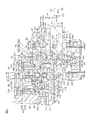
- FIG. 2 is a cross-sectional view showing a more specific configuration of the main part of FIG.
- the housing 24 is formed by forming a metal such as an aluminum alloy into a cylindrical shape.
- the housing 24 includes first to third housings 51 to 53.
- first to eighth bearings 31 to 38 are accommodated.
- the first to fifth bearings 31 to 35 and the seventh to eighth bearings 37 to 38 are rolling bearings such as angular ball bearings.
- the sixth bearing 36 is a rolling bearing such as a needle roller bearing.
- the first housing 51 has a cylindrical shape, constitutes a differential mechanism housing that houses the transmission ratio variable mechanism 5 as a differential mechanism, and a motor housing that houses the transmission ratio variable mechanism motor 23. It is composed.
- One end of the first housing 51 is covered with an end wall member 54.
- One end of the first housing 51 and the end wall member 54 are fixed to each other using a fastening member 55 such as a bolt.
- An annular convex portion 57 at one end of the second housing 52 is fitted to the inner peripheral surface 56 at the other end of the first housing 51.
- the first and second housings 51 and 52 are fixed to each other using a fastening member (not shown) such as a bolt.
- the second housing 52 has a cylindrical shape, and constitutes a sensor housing that houses the torque sensor 44 and a resolver housing that houses the motor resolver 43.
- the second housing 52 accommodates a bus bar 99 described later of the transmission ratio variable mechanism motor 23 and a lock mechanism 58 for locking the rotor 231 of the transmission ratio variable mechanism motor 23.
- the inner peripheral surface 60 at one end of the third housing 53 is fitted to the outer peripheral surface 59 at the other end of the second housing 52.
- the third housing 53 has a cylindrical shape and constitutes a speed reduction mechanism housing that houses the speed reduction mechanism 26.
- An end wall portion 61 is provided at the other end of the third housing 53.
- the end wall portion 61 has an annular shape and covers the other end of the third housing 53.
- FIG. 3 is an enlarged view of the transmission ratio variable mechanism 5 of FIG. 2 and its surroundings. Referring to FIG. 3, the input member 20, the output member 22 of the transmission ratio variable mechanism 5, and the inner ring 391 of the raceway ring unit 39 each have an annular shape.
- the input member 20 includes an input member main body 201 and a cylindrical member 202.
- the cylindrical member 202 is disposed radially inward of the input member main body 201 and is coupled to the input member main body 201 so as to be rotatable together.
- the first shaft 11 is connected to the tubular member 202 so as to be able to rotate along with the tubular member 202 by being inserted through the insertion hole 202 a of the tubular member 202.
- the second shaft 12 is connected to the output member 22 so as to be able to rotate along with the output member 22 by passing through the insertion hole 22 a of the output member 22.
- the first and second shafts 11 and 12 include opposed end portions 11a and 12a that face each other. These opposed end portions 11a and 12a are supported coaxially and relatively rotatably by a support mechanism 133.
- the support mechanism 133 includes a cylindrical member 202 of the input member 20 and an eighth bearing 38. That is, the cylindrical member 202 constitutes a part of the input member 20 and a part of the support mechanism 133.
- the cylindrical member 202 surrounds the opposing end portions 11a and 12a of the first and second shafts 11 and 12, respectively.
- One end of the cylindrical member 202 faces the first bearing 31 in the radial direction.
- the other end of the cylindrical member 202 is an annular portion 200 that faces the opposed end portion 12a of the second shaft 12 in the radial direction.
- the annular portion 200 surrounds the opposite end portion 12a of the second shaft 12 over the entire circumference.
- a bearing holding hole 109 for the eighth bearing 38 is formed on the inner periphery of the annular portion 200.
- the opposite end 12 a of the second shaft 12 is inserted through the bearing holding hole 109.
- An eighth bearing 38 is interposed between the opposed end portion 12 a of the second shaft 12 and the bearing holding hole 109 of the annular portion 200.
- the inner ring 381 of the eighth bearing 38 is fitted to the outer peripheral surface of the opposed end portion 12a.
- the outer ring 382 of the eighth bearing 38 is fitted in the bearing holding hole 109.
- the eighth bearing 38 allows relative rotation between the tubular member 202 and the second shaft 12.
- the opposing end portion 11a of the first shaft 11 is inserted into the insertion hole 22a in the output member 22, and the eighth bearing 38 is interposed between the output member 22 and the opposing end portion 11a of the first shaft 11. It may be interposed.
- the inner ring 391 is disposed outward in the radial direction of the tubular member 202.
- the outer ring 392 is rotatably held in an inclined hole 63 formed in the inner peripheral portion 233 of the rotor 231 of the transmission ratio variable mechanism motor 23, and rotates around the first axis A with the rotor 231. To do.
- the relative movement of the outer ring 392 and the rotor 231 is restricted with respect to the axial direction S of the steering shaft 3.
- the race ring unit 39 performs Coriolis motion.
- the outer ring 392 may connect the input member 20 and the output member 22 so as to be differentially rotatable, and the inner ring 391 may be connected to the rotor 231 of the transmission ratio variable mechanism motor 23 so as to be rotatable together.
- the race ring unit 39 is an inner ring support type.
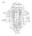
- FIG. 4 is a side view showing the main part of the transmission ratio variable mechanism 5 in cross section.
- the input member 20 and the output member 22 are shown as side surfaces, and the race ring unit 39 is shown as a cross section.
- the inner ring 391 of the bearing ring unit 39 includes a cylindrical first member 151, a cylindrical second member 152, and an annular inner ring main body 153.
- the first member 151, the second member 152, and the inner ring main body 153 are formed using different members from each other, and are coupled to rotate around the second axis B.
- the first member 151 is disposed adjacent to the input member 20 and includes a first tubular portion 154 and a first annular flange 155 provided at one end of the first tubular portion 154. is doing.
- the first annular flange 155 extends radially outward with respect to the first tubular portion 154.
- the first annular flange 155 includes a first end surface 71 and a first end surface 157 as a pair of end surfaces with respect to the axial direction S2 of the second axis B (hereinafter simply referred to as the axial direction S2).
- the other end surface facing the input member 20 is a first end surface 71 of the inner ring 391.
- the one end face 157 faces the first end face 71 in the axial direction S2.
- the one end surface 157 is in surface contact with the one end surface 153b of the inner ring main body 153 over the entire circumference.
- An inner side surface 158 facing the second member 152 is formed at the other end 154 a as an opposite end of the first tubular portion 154.
- the second member 152 is disposed adjacent to the output member 22 and has a second cylindrical portion 159 and a second annular flange 160 provided at one end of the second cylindrical portion 159. is doing.
- the second annular flange 160 extends radially outward with respect to the second cylindrical portion 159.
- the second annular flange 160 includes a second end surface 73 and one end surface 163 as a pair of end surfaces with respect to the axial direction S2. Of the pair of end surfaces of the second annular flange 160, the other end surface facing the output member 22 is a second end surface 73 of the inner ring 391. Of the pair of end surfaces of the second annular flange 160, the one end surface 163 faces the second end surface 73 in the axial direction S1.
- the one end surface 163 is in surface contact with the other end surface 153c of the inner ring main body 153 over the entire circumference.
- An inner side surface 164 that faces the first member 151 is formed at the other end 159 a as the opposite end of the second tubular portion 159.
- the other end 159a of the second tubular portion 159 and the other end 154a of the first tubular portion 154 are opposed to each other in the axial direction S2.
- the first and second cylindrical portions 154 and 159 include a restricting structure 165 for restricting relative rotation of the inner ring 391 in the circumferential direction C1 (hereinafter simply referred to as the circumferential direction C1).
- the restricting structure 165 includes a first undulating portion 166 formed on the inner side surface 158 of the first cylindrical portion 154, and a second undulating portion 167 provided on the inner side surface 164 of the second cylindrical portion 159. Is included.
- the first and second undulating portions 166, 167 are formed on the entire inner circumference along the circumferential direction C1 on the corresponding inner side surfaces 158, 164. These first and second undulating portions 166 and 167 have a waveform shape.
- each of the first and second undulating portions 166 and 167 has a rectangular wave shape.
- the first and second undulating portions 166 and 167 are engaged with each other in a concave-convex manner, and are in contact with each other with no gap in the circumferential direction C1.
- each of the other end portions 154a and 159a has the first tubular portion 154 (second tubular portion). 159) in a rectangular wave shape extending in the circumferential direction C3.
- the shapes of the edges of the other end portions 154a and 159a are the same.
- the fitting convex part 201 is formed in the other end part 154a of the first cylindrical part 154.
- a fitting recess 202 is formed at the other end 159 a of the second cylindrical portion 159.
- the fitting convex portion 201 and the fitting concave portion 202 are each formed in a rectangular wave shape extending in the circumferential direction C3.
- the relative rotation of the first and second members 151 and 152 in the circumferential direction C3 is restricted.
- An inner ring raceway 168 is formed on the outer peripheral surface 153 a of the inner ring main body 153.
- the inner ring raceway 168 is a raceway surface through which the rolling elements 393 pass, and has an arcuate cross section.
- the inner ring main body 153 is fixed to the first and second members 151 and 152. Specifically, one end surface 153 b of the inner ring main body 153 is along the first annular flange 155 and is in surface contact with the one end surface 157 of the first annular flange 155. Further, the other end surface 153 c of the inner ring main body 153 is along the second annular flange 160 and is in surface contact with the one end surface 163 of the second annular flange 160.
- the inner peripheral surface 153d of the inner ring main body 153 is press-fitted and fixed to the outer peripheral surfaces 171 and 172 of the first and second cylindrical portions 154 and 159, respectively.
- a first press-fit portion 173 and a first relief recess 174 are provided on the outer peripheral surface 171 of the first cylindrical portion 154.
- a second press-fit portion 175 and a second relief recess 176 are provided on the outer peripheral surface 172 of the second cylindrical portion 159.
- the first press-fit portion 173 is disposed at a position relatively far from the second member 152, and the first relief recess 174 is at a position relatively close to the second member 152.
- the first press-fit portion 173 has a relatively large diameter, and is press-fitted and fixed to the inner peripheral surface 153 d of the inner ring main body 153. Since the first relief recess 174 is formed to have a relatively small diameter, a gap D is formed between the inner ring main body 153 and the inner peripheral surface 153d, and is not in contact with the inner peripheral surface 153d. . That is, the first relief recess 174 is recessed with respect to the first press-fit portion 173.
- the second press-fit portion 175 is disposed at a position relatively far from the first member 151, and the second relief recess 176 is at a position relatively close to the first member 151.
- the second press-fit portion 175 has a relatively large diameter, and is press-fitted and fixed to the inner peripheral surface 153 d of the inner ring main body 153. Since the second relief recess 176 is formed to have a relatively small diameter, a gap D is formed with the inner peripheral surface 153d of the inner ring main body 153, and is not in contact with the inner peripheral surface 153d. . That is, the second relief recess 176 is recessed with respect to the second press-fit portion 175.
- the first and second relief recesses 174 and 176 are adjacent to each other in the axial direction S2, and the gap D is formed by the first and second relief recesses 174 and 176.
- the positions of the first and second relief recesses 174, 176 are associated with the position of the inner ring raceway 168.
- the length of the inner ring raceway 168 and the lengths of the first and second relief recesses 174, 176 are equal to each other.
- the inner ring raceway 168 and the first and second relief recesses 174, 176 are substantially aligned at one end and are aligned at the other end. Yes.
- first and second relief recesses 174 and 176 are arranged adjacent to each other between the first and second press-fit portions 173 and 175 with respect to the axial direction S2. Further, with respect to the radial direction R3 of the inner ring 391, the inner ring raceway 168 and the first and second relief recesses 174 and 176 are opposed to each other.
- a first uneven engagement portion 64 is provided on the input member main body 201 and the first member 151 of the inner ring 391. As a result, the input member 20 and the inner ring 391 can transmit power.
- a second uneven engagement portion 67 is provided on the second member 152 and the output member 22 of the inner ring 391. As a result, the inner ring 391 and the output member 22 can transmit power.
- the first concave / convex engaging portion 64 is formed on the first convex portion 65 formed on the power transmission surface 70 as one end surface of the input member main body 201 and the first end surface 71 of the inner ring 391.
- a first recess 66 that engages with the portion 65.
- the first convex portion 65 and the first concave portion 66 are formed on the corresponding power transmission surface 70 and the first end surface 71 over the entire area in the respective circumferential directions.
- Each first convex portion 65 has, for example, a semicircular cross section.
- Each first concave portion 66 has a shape that substantially matches the first convex portion 65.
- the power transmission surface 70 and the first end surface 71 are opposed to each other in the axial direction S of the steering shaft 3 (hereinafter simply referred to as the axial direction S). And the 1st end surface 71 is engaged so that power transmission is possible.
- 38 first protrusions 65 are formed.
- the number of first recesses 66 is different from the number of first protrusions 65.
- differential rotation can be generated between the input member main body 201 and the inner ring 391.
- the arrangement of the first convex portion 65 and the arrangement of the first concave portion 66 may be interchanged.
- the first convex portion 65 is formed on the first end surface 71 of the inner ring 391
- the first concave portion 66 is formed on the power transmission surface 70 of the input member 20.
- the second uneven engagement portion 67 includes a second convex portion 68 formed on the power transmission surface 72 as one end surface of the output member 22, and a second end surface 73 of the inner ring 391.
- a second concave portion 69 that engages with the second convex portion 68.
- the power transmission surface 72 and the second end surface 73 are opposed to each other with respect to the axial direction S, and the second concavo-convex engaging portion 67 engages the power transmission surface 72 and the second end surface 73 so that power can be transmitted.
- the second convex portion 68 of the second concave-convex engaging portion 67 has the same configuration as the first convex portion 65 of the first concave-convex engaging portion 64, and the second concave portion 69 is 1 has the same configuration as that of the first recess 66. More specifically, the power transmission surface 72 of the output member 22 has the same configuration as the power transmission surface 70 of the input member main body 201, and the second end surface 73 of the inner ring 391 is the second end surface 73 of the inner ring 391. 1 has the same configuration as the end face 71 of the first. Therefore, the detailed description of the second uneven engagement portion 67 is omitted.
- the second axis B of the inner ring 391 is inclined by a predetermined angle ⁇ with respect to the first axis A of the input member 20 and the output member 22, some of the first convex portions 65 and some of the The first recess 66 meshes with each other. Further, some of the second convex portions 68 and some of the second concave portions 69 are engaged with each other.
- a bevel gear is formed on each of the power transmission surface 70 of the input member main body 201 and the first end surface 71 of the inner ring 391 to form a first concave and convex engaging portion, and the second end surface 73 of the inner ring 391 and You may comprise a 2nd uneven
- the first convex portion and the second convex portion are each configured by teeth of the bevel gear, and the first concave portion and the second concave portion are grooves between the teeth of the bevel gear, respectively. Consists of.
- the rotor 231 of the transmission ratio variable mechanism motor 23 includes a cylindrical rotor core 85 extending in the axial direction S, and a permanent magnet 86 fixed to the outer peripheral surface of the rotor core 85.
- a torque sensor 44 is accommodated in the rotor core 85.
- the rotor core 85 surrounds both the first concavo-convex engaging portion 64 and the second concavo-convex engaging portion 67 over the entire circumference, and the torque sensor 44 is surrounded over the entire circumference.
- the length of the housing 24 in the axial direction S can be shortened.
- a retained hole 87 for the second bearing 32 is formed at one end of the rotor core 85.
- An annular bearing holding portion 88 is provided inside the held hole 87 in the radial direction.
- the bearing holding portion 88 is disposed on an annular convex portion 89 formed at one end of the first housing 51.
- the second bearing 32 is interposed between the held hole 87 and the bearing holding portion 88. As a result, one end of the rotor core 85 is rotatably supported by the first housing 51.
- a retained hole 90 for the fourth bearing 34 is formed in an intermediate portion of the rotor core 85.
- An annular bearing holding portion 91 is provided inside the held hole 90 in the radial direction.
- the bearing holding portion 91 is disposed in an annular extending portion 92 formed at one end of the second housing 52.
- the annular extending portion 92 has a cylindrical shape extending from the partition wall portion 93 provided at the other end of the second housing 52 to the one side S ⁇ b> 1 in the axial direction S, and is inserted through the rotor core 85.
- the fourth bearing 34 is interposed between the held hole 90 and the bearing holding portion 91. Thereby, the intermediate part of the rotor core 85 is rotatably supported by the annular extending part 92 of the second housing 52.
- the second and fourth bearings 32 and 34 are arranged with the bearing ring unit 39 sandwiched in the axial direction of the rotor 231.
- the rotor core 85 is supported at two locations in the axial direction S by the pair of bearings 32 and 34.
- the permanent magnet 86 of the rotor 231 has different magnetic poles alternately in the circumferential direction C2 of the steering shaft 3.
- the permanent magnet 86 has a configuration in which N poles and S poles are alternately arranged at equal intervals in the circumferential direction C2.
- the permanent magnet 86 is fixed to the outer peripheral surface of the intermediate portion of the rotor core 85. The positions of the permanent magnet 86 and a part of the transmission ratio variable mechanism 5 in the axial direction S are overlapped with each other.
- the stator 232 of the transmission ratio variable mechanism motor 23 is accommodated in the first housing 51.
- the stator 232 includes a stator core 95 formed by laminating a plurality of electromagnetic steel plates and an electromagnetic coil 96.
- the stator core 232 includes an annular yoke 97 and a plurality of teeth 98 arranged at equal intervals in the circumferential direction of the yoke 97 and projecting radially inward of the yoke 97.
- the outer peripheral surface of the yoke 97 is fixed to the inner peripheral surface of the first housing 51 by shrinkage fit or the like.
- An electromagnetic coil 96 is wound around each tooth 98.
- the bus bar 99 is arranged on the other side S2 in the axial direction S with respect to the stator 232.
- the bus bar 99 is accommodated in the second housing 52 in an annular state as a whole, and is connected to each electromagnetic coil 96 of the transmission ratio variable mechanism motor 23.
- the bus bar 99 supplies power from the drive circuit to each electromagnetic coil 96.
- the positions of the bus bar 99 and the third and fourth bearings 33 and 34 with respect to the axial direction S are overlapped.
- a lock mechanism 58 is disposed on the other side S ⁇ b> 2 in the axial direction S with respect to the bus bar 99.
- the lock mechanism 58 is for restricting the rotation of the rotor 231 of the transmission ratio variable mechanism motor 23 and is housed in one end of the second housing 52.
- the lock mechanism 58 includes a regulated portion 100 that can rotate with the rotor core 85 and a regulating portion 101 that regulates rotation of the regulated portion 100 by engaging with the regulated portion 100.
- the regulated portion 100 is an annular member.
- a recess 102 is formed on the outer peripheral surface of the regulated portion 100. The recess 102 is formed at one or a plurality of locations in the circumferential direction of the regulated portion 100.
- the rotor core 85 may be provided with the recess 102 directly. In this case, the rotor core 85 constitutes the restricted portion.
- the part of the regulated part 100 is overlapped with the part of the torque sensor 44 at the position in the axial direction S.
- the restricting portion 101 is disposed radially outward of the restricted portion 100.
- the restricting portion 101 is held by the second housing 52 and can be moved to the restricted portion 100 side.
- a motor resolver 43 is arranged on the other side S ⁇ b> 2 in the axial direction S with respect to the lock mechanism 58.
- the motor resolver 43 is accommodated in the second housing 52 and is located radially outward of the rotor core 85.
- the position of the motor resolver 43 and the torque sensor 44 are overlapped with each other in the axial direction S.
- the motor resolver 43 includes a resolver rotor 105 and a resolver stator 106.
- the resolver rotor 105 is fixed to the outer peripheral surface of the other end of the rotor core 85 so as to be able to rotate together.
- the resolver stator 106 is fixed to the second housing 52.
- the first shaft 11 is rotatably supported by the first housing 51 via the cylindrical member 202 of the input member 20 and the first bearing 31.
- the first bearing 31 is surrounded by the second bearing 32, and their positions are aligned with respect to the axial direction S.
- the third bearing 33 is interposed between the bearing holding hole 110 and the bearing holding portion 111.
- the bearing holding hole 110 is formed in the inner peripheral portion at the tip of the extending portion 92 of the second housing 52.
- the bearing holding portion 111 is formed on the outer periphery of the output member 22.
- the output member 22 is rotatably supported by the annular extending portion 92 of the second housing 52 via the third bearing 33.
- the third bearing 33 is surrounded by the fourth bearing 34, and their positions are aligned with respect to the axial direction S.
- an elastic member 113 as an urging member is disposed on one end side of the first housing 51.
- the elastic member 113 is formed using a disc spring, for example.
- the elastic member 113 biases the input member main body 201 in a biasing direction H1 (the other side S2 in the axial direction S) as a direction in which the input member main body 201 approaches the output member 22.
- the elastic member 113 may be a wave washer formed in a corrugated shape, or may be another elastic body such as a resin ring.
- the elastic member 113 biases the input member main body 201 toward the output member 22. Thereby, a preload is applied to each of the first concave and convex engaging portion 64 and the second concave and convex engaging portion 67.
- the elastic member 113 is held in the bearing holding hole 134.
- the bearing holding hole 134 is formed on the inner periphery of the annular convex portion 89 at one end of the first housing 51.
- the elastic member 113 urges (presses) one end surface of the outer ring 312 of the first bearing 31 held in the bearing holding hole 134 toward the urging direction H1.
- the outer ring 312 of the first bearing 31 is fitted to the bearing holding hole 134 so as to be relatively movable in the axial direction S.
- a lid member 135 is provided adjacent to the elastic member 113.
- the lid member 135 is screwed into a female screw part 134 a formed in the bearing holding hole 134.
- the lid member 135 receives the elastic member 113 and restricts the urging member 113 from moving in the direction H2 opposite to the urging direction H1.
- the inner ring 311 of the first bearing 31 is press-fitted and fixed to one end of the cylindrical member 202, and the cylindrical member 202 and the input member main body 201 can rotate together and move in the axial direction S.
- the inner ring 311 urges the input member main body 201 in the urging direction H ⁇ b> 1 under the urging force of the elastic member 113.
- the first convex portion 65 of the first concave-convex engaging portion 64 faces the first concave portion 66 in the urging direction H1.
- corrugated engaging part 67 is facing the 2nd convex part 68 in the urging
- An inner ring 331 of a third bearing 33 is press-fitted and fixed to the output member 22.
- the outer ring 332 of the third bearing 33 is fitted in the bearing holding hole 110 and is movable relative to the bearing holding hole 110 in the axial direction S.
- the outer ring 332 of the third bearing 33 is received by an annular step 114 disposed adjacent to the bearing holding hole 110, and movement in the urging direction H1 is restricted.
- the urging force transmitted to the input member 20 is transmitted in the order of the first concavo-convex engaging portion 64, the second concavo-convex engaging portion 67, and the output member 22, and further the inner ring 331, rolling elements and outer ring 332 of the third bearing 33. It is transmitted to.
- the urging force transmitted to the outer ring 332 of the third bearing 33 is received by the annular step portion 114.
- the rolling elements 393, the outer ring 392 of the track ring unit 39 and the rotor 231 of the transmission ratio variable mechanism motor 23 are It moves together in the direction S.
- the outer ring 392 of the track ring unit 39 is press-fitted and fixed in the inclined hole 63 of the rotor core 85.
- the outer rings 322 and 342 of the second bearing 32 and the fourth bearing 34 are fitted into the corresponding annular held holes 87 and 90 of the rotor core 85 so that the rotor core 85 is relative to the axial direction S. Supports movable.
- the inner ring 321 of the second bearing 32 is press-fitted and fixed to the bearing holding portion 88 of the annular convex portion 89.
- the inner ring 341 of the fourth bearing 34 is press-fitted and fixed to the bearing holding portion 91 of the annular extending portion 92 of the second housing 52.
- the input member 20 and the output member 22 can be moved relative to the bearing ring unit 39 in the urging direction H1 and in the opposite direction H2 (axial direction S).
- the upper limit of the amount by which the input member 20 and the output member 22 can move in the axial direction S with respect to the housing 24 is restricted.
- the tip surface 89 a of the annular convex portion 89 of the first housing 51 is opposed to the annular surface 201 a of the input member main body 201 in the axial direction S.
- the tip end surface 92 a of the annular extending portion 92 of the second housing 24 is opposed to the annular surface 22 b of the output member 22 in the axial direction S.
- a predetermined gap E ⁇ b> 1 is provided between the front end surface 89 a of the annular protrusion 89 and the annular surface 201 a of the input member main body 201 in the initial state at the time of factory shipment.
- a predetermined gap E ⁇ b> 2 is provided between the tip end surface 92 a of the annular extending portion 92 and the annular surface 22 b of the output member 22.
- the first convex portion 65 and the first concave portion 66 in the first concave / convex engaging portion 64 can be maintained in a positively engaged state, so that the first convex portion 65 and the first concave portion 66 can be maintained. It is possible to prevent tooth skipping (slipping) between them.
- the second convex portion 68 and the second concave portion 69 in the second concave-convex engaging portion 67 can be maintained in a reliable engagement state, the second convex portion 68 and the second concave portion 69 can be maintained. It is possible to prevent tooth skipping (slipping).
- the elastic member 113 may be used to bias the output member 22 in a direction in which the output member 22 approaches the input member 20 (a direction H2 opposite to the biasing direction H1).
- the elastic member 113 is held in the bearing holding hole 110 that holds the third bearing 33 and is sandwiched between the annular stepped portion 114 and the outer ring 332 of the third bearing 33.
- the urging force of the elastic member 113 includes the third bearing 33, the output member 22, the second uneven engagement portion 67, the first uneven engagement portion 64, the input member 20, the inner ring 311 of the first bearing 31, the rolling force.
- the moving body, the outer ring 312 and the lid member 135 are transmitted in this order and are received by the first housing 51.
- the preload is applied to each of the first and second concave and convex engaging portions 64 and 67 using the elastic member 113.
- a constant pressure preload structure as a structure capable of making the preload to the first and second concave and convex engaging portions 64 and 67 substantially constant. Therefore, preload management at the time of manufacture can be facilitated.
- a structure that can regulate the amount of movement of the input member 20 and the output member 22 in the axial direction S relative to the inner ring 391 is employed.
- the support mechanism 133 does not prevent the displacement of the inner ring 391 in the axial direction S.
- the outer ring 382 of the eighth bearing 38 of the support mechanism 133 is fitted into the bearing holding hole 109 of the cylindrical member 202 and is movable in the axial direction S with respect to the bearing holding hole 109.
- the inner ring 381 of the eighth bearing 38 is press-fitted and fixed to the opposed end portion 12 a of the second shaft 12.
- the outer ring 382 of the eighth bearing 38 may be press-fitted and fixed in the bearing holding hole 109, and the inner ring 381 may be loosely fitted to the opposed end portion 12a.
- the torque sensor 44 is disposed radially inward of the rotor core 85 of the transmission ratio variable mechanism motor 23.
- the torque sensor 44 includes a multipolar magnet 115 fixed to an intermediate portion of the second shaft 12 and magnetic yokes 116 and 117 supported on one end of the third shaft 13.
- the magnetic yokes 116 and 117 are a pair of soft magnetic bodies that are arranged in a magnetic field generated by the multipolar magnet 115 to form a magnetic circuit.
- the multipolar magnet 115 is a cylindrical permanent magnet, and a plurality of poles (the same number of N and S respectively) are magnetized at equal intervals in the circumferential direction.
- the magnetic yokes 116 and 117 surround the multipolar magnet 115.
- Each of the magnetic yokes 116 and 117 is molded on a synthetic resin member 118.
- the synthetic resin member 118 is coupled to one end of the third shaft 13 so as to be able to rotate together.
- the torque sensor 44 further includes a pair of magnetism collecting rings 119 and 120 for inducing magnetic flux from the magnetic yokes 116 and 117.
- the pair of magnetism collecting rings 119 and 120 are annular members formed using a soft magnetic material.
- the pair of magnetism collecting rings 119 and 120 surround the magnetic yokes 116 and 117 and are magnetically coupled to the magnetic yokes 116 and 117, respectively.
- the pair of magnetism collecting rings 119 and 120 are separated from each other in the axial direction S and face each other.
- the magnetism collecting rings 119 and 120 are molded by the synthetic resin member 121.
- the synthetic resin member 121 is held by the annular extending portion 92 of the second housing 52.
- Magnetic flux is generated in the magnetic yokes 116 and 117 in accordance with the relative rotational amounts of the second and third shafts 12 and 13.
- This magnetic flux is induced by the magnetic flux collecting rings 119 and 120 and detected by a Hall IC (not shown) embedded in the synthetic resin member 121. Thereby, the magnetic flux density according to the torque applied to the second shaft 12 can be detected.
- a fifth bearing 35 is arranged on the other side S ⁇ b> 2 in the axial direction S with respect to the torque sensor 44.
- the fifth bearing 35 is interposed between a bearing holding portion 122 formed on the outer periphery of one end of the third shaft 13 and a bearing holding hole 123 formed in the partition wall portion 93 of the second housing 52. Yes.
- the bearing holding hole 123 rotatably supports one end of the third shaft 13 through the fifth bearing 35.
- the third shaft 13 surrounds the second shaft 12 and the torsion bar 14. Specifically, an insertion hole 124 opened at one end of the third shaft 13 is formed in the third shaft 13. The other end of the second shaft 12 is inserted through the insertion hole 124. An insertion hole 125 extending in the axial direction S is formed in the second shaft 12, and the torsion bar 14 is inserted through the insertion hole 125.
- One end of the torsion bar 14 is connected to one end of the insertion hole 125 of the second shaft 12 so as to be able to rotate together by serration fitting or the like.
- the other end of the torsion bar 14 is connected to the insertion hole 124 of the third shaft 13 by serration fitting or the like so as to be able to rotate together.
- a space in the radial direction of the annular extending portion 92 of the second housing 52 serves as a torque sensor housing chamber 126.
- a structure for suppressing the intrusion of the lubricant into the torque sensor housing chamber 126 is further provided.
- a third bearing 33 with a seal disposed at one end of the annular extending portion 92 of the second housing 52, and an output member 22 disposed radially inward of the third bearing 33
- One end of the torque sensor housing chamber 126 is closed by the second shaft 12 disposed radially inward of the output member 22.
- the second shaft 12 and the third shaft 13 are relatively rotatable via a sixth bearing 36.
- the sixth bearing 36 is surrounded by the worm wheel 28 of the speed reduction mechanism 26.
- the speed reduction mechanism 26 is accommodated in the accommodation chamber 128.
- the storage chamber 128 is partitioned by the outer peripheral portion 127 of the third housing 53, the end wall portion 61, and the partition wall portion 93 of the second housing 52. A part of the worm wheel 28 and the sixth bearing 36 overlap with each other in the position in the axial direction S.
- a seventh bearing 37 is interposed between the intermediate portion of the third shaft 13 and the end wall portion 61 of the third housing 53.
- the end wall portion 61 supports the third shaft 13 via the seventh bearing 37 so as to be rotatable.
- the inner ring 371 of the seventh bearing 37 is sandwiched between an annular step 129 formed on the outer peripheral portion of the third shaft 13 and a nut member 130 screwed to the outer peripheral portion of the third shaft 13. Yes.
- the outer ring 372 of the seventh bearing 37 is sandwiched between an annular step 131 formed in the third housing 53 and a retaining ring 132 held by the third housing 53.
- the first and second members 151 and 152 of the inner ring 391 of the track ring unit 39 are formed separately from each other and are coupled to each other so as to be able to move together.
- the corresponding recesses 66 and 69 can be formed in the first and second end faces 71 and 73 of the inner ring 391 with less labor as follows, for example. .
- the first recess 66 is formed in one end surface (corresponding to the first end surface 71) of the manufacturing intermediate of the first member 151, and separately from this, one end surface of the manufacturing intermediate of the second member 152
- the second recess 69 can be formed on the first and second end surfaces 71, 73.
- the following laborious work is required. It is. That is, after forming a recess on one end surface, a laborious operation is required in which the recess is formed on the other end surface in a state where the recess is positioned with respect to the recess on the one end surface.
- the first and second members 151 and 152 can be formed separately, the above laborious work is unnecessary.
- the first and second members 151 and 152 may be combined.
- the inner ring raceway 168 can be formed by cutting the intermediate product of the inner ring main body 153 in a single product state.
- the inner ring in addition to forming recesses on a pair of end faces of an inner ring manufacturing intermediate made of a single member, the inner ring is formed by forming an inner ring raceway. It is not necessary to set the relative position of each other with high accuracy when forming 66 and 69, and the labor for manufacturing the inner ring 391 can be reduced.
- the inner ring main body 153 for example, a bearing inner ring of a standard size defined by a standard such as JIS (Japanese Industrial Standard) can be used, and the inner ring main body 153 can be formed at a lower cost.
- the inner ring main body 153 is sandwiched between the first annular flange 155 of the first member 151 and the second annular flange 160 of the second member 152.
- wheel main body 153 and the 1st and 2nd members 151 and 152 can be made higher.
- the one end surfaces 157 and 163 of the annular flanges 155 and 160 are along the corresponding end surfaces 153b and 153c of the inner ring main body 153, and the annular flanges 155 and 160
- the other end surfaces are the corresponding first and second end surfaces 71 and 73.
- the thrust force that acts on the first end surface 71 of the inner ring 391 from the input member 20 and the thrust force that acts on the second end surface 73 of the inner ring 391 from the output member 22 result in the annular flanges 155 and 160 as a whole.
- the inner ring main body 153 is tightened. Thereby, the mutual coupling force of the 1st and 2nd members 151 and 152 and the inner ring main body 153 can be raised more.
- first and second relief recesses 174 and 176 are provided. Thereby, the fluctuation
- the first and second relief recesses 174 and 176 are sandwiched between the first and second press-fit portions 173 and 175.
- the inner ring raceway 168 and the first and second relief recesses 174 and 176 It is opposed to the radial direction R3 of 391.
- the other end portions 154a, 159a (opposing end portions) of the first and second cylindrical portions 154, 159 are circumferential directions C3 of the cylindrical portions 154, 159 when viewed along the radial direction R2. It is formed in a rectangular wave shape extending in the direction.
- the inner ring 391 can be rotated around the first axis A by rotating the outer ring 392 of the raceway ring unit 39 around the first axis A by the transmission ratio variable mechanism motor 23.
- the inner ring 391 can perform Coriolis motion (swing motion).
- a first uneven engagement portion 64 and a second uneven engagement portion 67 are provided on both sides of the inner ring 391.
- the opposed end portions 11a and 12a of the first and second shafts 11 and 12 are supported by a support mechanism 133 so as to be relatively rotatable.
- the runout of the opposing end portions 11a and 12a of the first and second shafts 11 and 12 can be further reduced.
- the eccentric rotation of the input member 20 and the output member 22 with respect to the first axis A can be further reduced.
- the first member 151 and the second member 152 of the inner ring 391 are changed from the input member 20 and the output member 22 to each other. It can suppress more reliably that an excessive force acts. As a result, it is possible to more reliably prevent the relative positions of the first and second members 151 and 152 from shifting.
- the input member 20 supports the first shaft 11 and supports the opposing end portion 12 a of the second shaft 12 via the eighth bearing 38.
- the support mechanism 133 can be realized at low cost. Further, the eccentric rotation of the opposed end portions 11a and 12a of the shafts 11 and 12 with respect to the first axis A can be more reliably reduced.
- a steering assist force applying mechanism 19 is provided in addition to the transmission ratio variable mechanism 5.
- the transmission ratio variable mechanism motor 23 can be reduced in cost and size.
- the steering assist force generated by the steering assist motor 25 is transmitted to the steered wheels 4L and 4R via the third shaft 13 and the like, so that the steered wheels 4L are not transmitted via the transmission ratio variable mechanism 5. , Transmitted to 4R. Therefore, the large torque from the steering assist motor 25 can be prevented from being transmitted to the transmission ratio variable mechanism 5, so that the allowable torque of each component of the transmission ratio variable mechanism 5 can be further reduced.
- each component of the transmission ratio variable mechanism 5 can be further reduced.
- the torque acting between the first and second members 151 and 152 of the inner ring 391 can be small, and the relative position of these members 151 and 152 can be more reliably suppressed.
- the biasing force by the elastic member 113 can be adjusted by adjusting the screwing amount of the lid member 135 into the female screw part 134a. Further, the urging force of the elastic member 113 can be transmitted to the inner ring 311 of the first bearing 31 via the outer ring 312 of the first bearing 31, and preload can be reliably applied to the first bearing 31. .
- the second and fourth bearings 32 and 34 support the rotor 231 so as to be movable in the axial direction S.
- the inner ring 391 moves in the axial direction of the rotor 231
- the outer ring 392 and the rotor 231 can move in the axial direction of the rotor 231.
- unnecessary force is generated between the inner ring 391 and the outer ring 392. It can prevent acting.
- first and second undulating portions 166 and 167 having a triangular wave shape may be used.
- first cylindrical portion 154A second cylindrical portion 159A
- each of the other end portions 154aA and 159aA corresponds to the first cylindrical portion 154A (second cylindrical portion).
- 159A) is formed in a triangular wave shape extending in the circumferential direction C3.
- the fitting convex portion 201A is formed on the other end portion 154aA of the first cylindrical portion 154A
- the fitting concave portion 202A is formed on the other end portion 159aA of the second cylindrical portion 159A. Yes.
- the fitting convex portion 201A and the fitting concave portion 202A are each formed in a triangular wave shape extending in the circumferential direction C3.
- the relative rotation of the first and second members 151A, 152A in the circumferential direction C3 is restricted.
- the relative rotation of the first and second members 151A and 152A can be reliably restricted by the fitting of the triangular wave-shaped fitting concave portion 202A and the fitting convex portion 201A.
- the inner ring of the track ring unit is rotationally driven by the transmission ratio variable mechanism motor, the outer ring and the input member are connected by the first uneven engagement portion, and the outer ring and the output member are further connected by the second uneven engagement member.
- the outer ring is the first race ring, and the inner ring is the second race ring.
- the outer ring includes a first member formed with a first end face, a second member formed with a second end face, and an outer ring main body fixed to the first and second members. It becomes the composition containing.
- SYMBOLS 1 Vehicle steering device, 2 ... Steering member, 4L, 4R ... Steering wheel, 5 ... Transmission ratio variable mechanism, 11 ... 1st shaft, 11a ... Opposing end part, 12 ... 2nd shaft, 12a ... Opposing end 13, a third shaft (a shaft interposed between the output member and the steered wheel), 19, a steering assist force applying mechanism, 20, an input member, 22, an output member, 23, a transmission ratio variable mechanism motor ( Actuator), 25 ... Steering assist motor (second actuator), 26 ... Deceleration mechanism (transmission mechanism), 38 ... Eighth bearing (bearing of support mechanism), 64 ... First uneven engagement portion, 65 ... 1st convex part, 66 ...
- first cylindrical part, 154a, 154aA opposite end part of first cylindrical part
- other end part 155 ... first annular flange, 157 ... one end surface (of the annular flange), 159 ... second cylindrical part, 159a, 159aA ... (opposite end part of the second cylindrical part) the other end part, 160 ... second annular flange, 163 ... ( One end surface (of the annular flange), 168 ... inner ring raceway, 171 ... outer periphery (of the first cylindrical portion), 172 ... outer periphery of (the second cylindrical portion), 173 ... first press-fit portion, 174 ...
Abstract
A transmission ratio changing mechanism (5) includes an input member (20) and an output member (22) which are able to rotate about a first axis (A), an inner ring (391) for connecting the input and output members (20, 22) to each other such that the input and output members are differentially rotatable, an outer ring (392), and a motor (23) for the transmission ratio changing mechanism, the motor being capable of rotationally driving the outer ring (392). A second axis (B) as the center axis of the inner ring (391) and the outer ring (392) is tilted relative to the first axis (A). The transmission ratio changing mechanism (5) is provided with projection/recess engaging sections (64, 67) which include projections (65, 68) provided on either each end surface (71, 73) of the inner ring (391) or a power transmitting surface (70, 72) corresponding to the end surface (71, 73), and also include recesses (66, 69) provided in the other and engaging with the projections (65, 68). The inner ring (391) has a first member (151; 151A) forming the first end surface (71) and a second member (152; 152A) forming the second end surface (73). The first and second members (151, 152; 151A, 152A) are formed as separate bodies and are joined to each other so as to be movable together.
Description
本発明は、伝達比可変機構および車両用操舵装置に関する。
The present invention relates to a transmission ratio variable mechanism and a vehicle steering apparatus.
変速装置として、例えば、偏心歯車を用いたもの(例えば、特許文献1参照)や、遊星歯車を用いたもの(例えば、特許文献2参照)や、揺動歯車を用いたもの(例えば、特許文献3参照)が知られている。特許文献2,3には、車両用操舵装置に適用された変速装置が記載されている。
As a transmission, for example, one using an eccentric gear (for example, see Patent Document 1), one using a planetary gear (for example, see Patent Document 2), or one using a rocking gear (for example, Patent Document 1) 3) is known. Patent Documents 2 and 3 describe a transmission that is applied to a vehicle steering system.
特許文献3では、互いに対向する第1および第4歯車と、第1および第4歯車の間に配置され第1および第4歯車に対して傾斜した揺動歯車と、を備えている。揺動歯車は、第1歯車に噛合する第2歯車と、第4歯車に噛合する第3歯車とを含んでいる。これら第2および第3歯車は、単一の部材に形成されている。
このため、揺動歯車を形成する際には、揺動歯車の製造中間体の一方の端面に第2歯車を形成した後、製造中間体の他方の端面に第3歯車を形成する。このとき、第2歯車に対して第3歯車の位置決めを精度よく設定しなければならず、揺動歯車の製造に手間がかかる。Patent Document 3 includes first and fourth gears that face each other, and an oscillating gear that is disposed between the first and fourth gears and is inclined with respect to the first and fourth gears. The swing gear includes a second gear that meshes with the first gear and a third gear that meshes with the fourth gear. These second and third gears are formed as a single member.
Therefore, when forming the oscillating gear, the second gear is formed on one end surface of the manufacturing intermediate of the oscillating gear, and then the third gear is formed on the other end surface of the manufacturing intermediate. At this time, the positioning of the third gear must be accurately set with respect to the second gear, and it takes time to manufacture the swing gear.
このため、揺動歯車を形成する際には、揺動歯車の製造中間体の一方の端面に第2歯車を形成した後、製造中間体の他方の端面に第3歯車を形成する。このとき、第2歯車に対して第3歯車の位置決めを精度よく設定しなければならず、揺動歯車の製造に手間がかかる。
Therefore, when forming the oscillating gear, the second gear is formed on one end surface of the manufacturing intermediate of the oscillating gear, and then the third gear is formed on the other end surface of the manufacturing intermediate. At this time, the positioning of the third gear must be accurately set with respect to the second gear, and it takes time to manufacture the swing gear.
本発明は、かかる背景のもとでなされたもので、製造にかかる手間を低減することのできる伝達比可変機構および車両用操舵装置を提供することを目的とする。
上記目的を達成するため、本発明の好ましい態様は、第1の軸線の回りに回転可能な入力部材と、上記第1の軸線の回りに回転可能な出力部材と、第1および第2の端面を有し、且つ上記入力部材および上記出力部材を差動回転可能に連結する第1の軌道輪と、上記第1の軌道輪を転動体を介して回転可能に支持する第2の軌道輪と、上記第2の軌道輪を回転駆動可能なアクチュエータと、を含む。上記第1および上記第2の軌道輪の中心軸線としての第2の軸線が、上記第1の軸線に対して傾斜している。上記入力部材および上記出力部材は、上記第1の軌道輪の対応する上記端面に対向する動力伝達面を有している。上記第1の軌道輪の各上記端面および当該端面に対応する上記動力伝達面を動力伝達可能に係合させる凹凸係合部が設けられている。上記凹凸係合部は、上記第1の軌道輪の各上記端面および当該端面に対応する上記動力伝達面の一方に設けられた凸部と、他方に設けられ上記凸部と係合する凹部とを含む。上記第1の軌道輪は、上記第1の端面を形成する第1の部材と、上記第2の端面を形成する第2の部材とを有している。上記第1および上記第2の部材は、互いに別体に形成され且つ互いに同行移動可能に結合されている。 The present invention has been made under such a background, and an object thereof is to provide a transmission ratio variable mechanism and a vehicle steering device that can reduce the labor required for manufacturing.
In order to achieve the above object, preferred embodiments of the present invention include an input member rotatable around a first axis, an output member rotatable around the first axis, and first and second end faces. And a first race ring that connects the input member and the output member so as to be differentially rotatable, and a second race ring that rotatably supports the first race ring via a rolling element. And an actuator capable of rotationally driving the second raceway ring. A second axis as a central axis of the first and second races is inclined with respect to the first axis. The input member and the output member have a power transmission surface facing the corresponding end surface of the first track ring. An uneven engagement portion is provided for engaging each end face of the first raceway ring and the power transmission face corresponding to the end face so as to be able to transmit power. The concavo-convex engaging portion includes a convex portion provided on one of the end surfaces of the first track ring and the power transmission surface corresponding to the end surface, and a concave portion provided on the other side and engaged with the convex portion. including. The first track ring includes a first member that forms the first end face, and a second member that forms the second end face. The first and second members are formed separately from each other and coupled so as to be able to move together.
本態様によれば、第1の軌道輪の第1および第2の端面の、凸部または凹部の形成は、例えば、以下のようにして行われる。すなわち、第1の部材の製造中間体のうち第1の端面に相当する一端面に凸部または凹部を形成し、これとは別に、第2の部材の製造中間体のうち第2の端面に相当する一端面に凸部または凹部を形成することにより、凸部または凹部が形成される。本態様とは異なる構成の場合、例えば、単一の部材からなる第1の軌道輪の製造中間体の相対向する一対の端面に凸部または凹部を形成する場合には、以下のような手間のかかる作業が必要である。すなわち、一方の端面に凸部または凹部を形成した後に、この一方の端面の凸部または凹部に対して精度よく位置決めした状態で、他方の端面に凸部または凹部を形成するという、手間のかかる作業が必要である。これに対し、本態様であれば、第1および第2の部材を別々に形成することができるので、上記のような手間がかからない。
According to this aspect, the formation of the convex portions or the concave portions on the first and second end faces of the first raceway ring is performed as follows, for example. That is, a convex portion or a concave portion is formed on one end surface corresponding to the first end surface of the manufacturing intermediate of the first member, and separately from the second end surface of the manufacturing intermediate of the second member. A convex portion or a concave portion is formed by forming a convex portion or a concave portion on the corresponding one end surface. In the case of a configuration different from this aspect, for example, in the case where a convex portion or a concave portion is formed on a pair of opposed end faces of the first intermediate ring manufacturing intermediate made of a single member, the following troubles are required. This work is necessary. That is, after forming a convex portion or a concave portion on one end surface, it takes time and effort to form a convex portion or a concave portion on the other end surface in a state of being accurately positioned with respect to the convex portion or concave portion on the one end surface. Work is necessary. On the other hand, if it is this aspect, since the 1st and 2nd member can be formed separately, it does not require the above troubles.
また、上記第1の軌道輪は内輪であり、上記内輪は、内輪軌道が外周に形成された環状の内輪本体を有し、上記第1および上記第2の部材は、上記内輪本体に固定されていれば、好ましい。この場合、内輪本体と第1の部材および第2の部材がそれぞれ別体に形成されている。これにより、内輪本体の製造中間体について、単品の状態で切削加工等を施して内輪軌道を形成することができる。例えば、単一の部材からなる第1の軌道輪の製造中間体の一対の端面に凹部または凸部を形成することに加え、内輪軌道を形成することで内輪を形成する場合と比べて、製造にかかる手間をより少なくできる。
The first race ring is an inner ring, the inner ring has an annular inner ring main body having an inner ring raceway formed on the outer periphery, and the first and second members are fixed to the inner ring main body. If it is, it is preferable. In this case, the inner ring main body, the first member, and the second member are formed separately. Thereby, about the manufacturing intermediate body of an inner ring | wheel main body, cutting etc. can be given in the state of a single item, and an inner ring track can be formed. For example, compared to the case where the inner ring is formed by forming the inner ring raceway in addition to the formation of the concave or convex portions on the pair of end faces of the intermediate body of the first race ring made of a single member. Less time and effort.
また、上記第1および上記第2の部材のそれぞれは、上記内輪本体の内周に嵌合された筒状部と、上記筒状部の一端から上記筒状部の径方向外方へ延び上記内輪本体の対応する端面に沿う環状フランジとを有し、上記第1の軌道輪としての上記内輪の上記第1および上記第2の端面は、各上記環状フランジに設けられていれば、好ましい。この場合、第1の部材の環状フランジと第2の部材の環状フランジとで、内輪本体を挟持することができる。これにより、内輪本体と、第1および第2の部材との互いの結合力をより高くできる。
Each of the first and second members includes a cylindrical part fitted to the inner periphery of the inner ring main body, and extends radially outward from the cylindrical part from one end of the cylindrical part. It is preferable that the first and second end surfaces of the inner ring as the first race ring are provided on each of the annular flanges. In this case, the inner ring main body can be sandwiched between the annular flange of the first member and the annular flange of the second member. Thereby, the mutual coupling | bonding force of an inner ring | wheel main body and a 1st and 2nd member can be made higher.
また、上記第2の軸線の軸方向に関して、各上記環状フランジの一端面が、上記内輪本体の上記対応する端面に沿わされており、各上記環状フランジの他端面が、対応する上記第1および上記第2の端面であれば、好ましい。この場合、入力部材から内輪の対応する端面に作用するスラスト力と、出力部材から内輪の対応する端面に作用するスラスト力は、全体として各環状フランジが内輪本体を締め付けるような力となる。これにより、第1および第2の部材と、内輪本体の互いの結合力をより高めることができる。
In addition, with respect to the axial direction of the second axis, one end surface of each annular flange extends along the corresponding end surface of the inner ring body, and the other end surface of each annular flange corresponds to the corresponding first and second The second end face is preferable. In this case, the thrust force that acts on the corresponding end surface of the inner ring from the input member and the thrust force that acts on the corresponding end surface of the inner ring from the output member are forces that each annular flange tightens the inner ring body as a whole. Thereby, the mutual binding force of the first and second members and the inner ring main body can be further increased.
また、上記第1および上記第2の部材の上記筒状部の外周は、上記内輪本体の内周に圧入された圧入部と、上記圧入部に対して窪んだ逃げ凹部とを含み、上記逃げ凹部と上記内輪本体の内周との間に隙間が設けられ、上記内輪の軸方向に関して、上記第1および上記第2の部材の上記圧入部の間に、上記第1および上記第2の部材の上記逃げ凹部が、互いに隣接して配置されていれば、好ましい。この場合、内輪本体と、第1および第2の部材とを圧入結合している。これにより、内輪本体と、第1および第2の部材との結合強度を十分に確保できる。また、逃げ凹部が設けられている。これにより、内輪本体が圧入部に圧接されることに起因する、軸受の内部すきまの変動を抑制することができる。したがって、軸受の内部すきまの管理が容易である。
The outer periphery of the cylindrical portion of the first and second members includes a press-fit portion that is press-fitted into the inner periphery of the inner ring main body, and a relief recess that is recessed with respect to the press-fit portion. A gap is provided between the recess and the inner periphery of the inner ring main body, and the first and second members are interposed between the press-fit portions of the first and second members with respect to the axial direction of the inner ring. It is preferable if the relief recesses are arranged adjacent to each other. In this case, the inner ring main body and the first and second members are press-fitted and coupled. Thereby, sufficient coupling strength between the inner ring main body and the first and second members can be secured. A relief recess is provided. Thereby, the fluctuation | variation of the internal clearance of a bearing resulting from an inner ring main body being press-contacted to a press-fit part can be suppressed. Therefore, it is easy to manage the internal clearance of the bearing.
また、上記内輪軌道と各上記逃げ凹部とは、上記内輪の径方向に相対向していれば、好ましい。この場合、内輪本体が圧入部に圧接されることに起因する軸受の内部すきまの変動を、より確実に抑制することができる。したがって、軸受の内部すきまの管理がより容易である。
また、上記第1および第2の部材の上記筒状部は、互いに対向する対向端部を含み、各上記対向端部の一方に形成された嵌合凹部と他方に形成された嵌合凸部とが互いに嵌合することにより、上記第1および第2の部材の相対回転が規制されていれば、好ましい。この場合、第1および第2の部材の相対回転を確実に規制することができる。その結果、内輪の周方向に関して、第1の端面に形成された凹部または凸部と、第2の端面に形成された凹部または凸部との位相がずれてしまうことを抑制できる。したがって、凹凸係合部の理想的な噛み合い状態を長期に亘って確実に維持できる。 Further, it is preferable that the inner ring raceway and each relief recess are opposed to each other in the radial direction of the inner ring. In this case, fluctuations in the internal clearance of the bearing due to the inner ring main body being pressed against the press-fit portion can be more reliably suppressed. Therefore, it is easier to manage the internal clearance of the bearing.
Moreover, the said cylindrical part of the said 1st and 2nd member contains the opposing edge part which mutually opposes, the fitting recessed part formed in one side of each said opposing edge part, and the fitting convex part formed in the other Are preferably fitted to each other so that relative rotation of the first and second members is restricted. In this case, the relative rotation of the first and second members can be reliably restricted. As a result, with respect to the circumferential direction of the inner ring, it is possible to suppress the phase shift between the concave portion or the convex portion formed on the first end surface and the concave portion or the convex portion formed on the second end surface. Therefore, the ideal meshing state of the concave and convex engaging portion can be reliably maintained over a long period of time.
また、各上記対向端部は、上記筒状部の径方向に沿って見たときに、上記筒状部の周方向に延びる矩形波形状に形成されていれば、好ましい。この場合、嵌合凹部と嵌合凸部との嵌合によって、第1および第2の部材の相対回転を確実に規制できる。
また、各上記対向端部は、上記筒状部の径方向に沿って見たときに、上記筒状部の周方向に延びる三角波形状に形成されていれば、好ましい。この場合、三角波形状の嵌合凹部と嵌合凸部との嵌合によって、第1および第2の部材の相対回転を確実に規制できる。 Further, it is preferable that each of the opposed end portions is formed in a rectangular wave shape extending in the circumferential direction of the cylindrical portion when viewed along the radial direction of the cylindrical portion. In this case, the relative rotation of the first and second members can be reliably regulated by the fitting between the fitting concave portion and the fitting convex portion.
Further, it is preferable that each of the opposed end portions is formed in a triangular wave shape extending in the circumferential direction of the cylindrical portion when viewed along the radial direction of the cylindrical portion. In this case, the relative rotation of the first and second members can be reliably restricted by fitting the triangular wave-shaped fitting concave portion and the fitting convex portion.
また、上記アクチュエータは、伝達比可変機構用モータを含み、上記伝達比可変機構用モータは、上記第2の軌道輪とは上記第1の軸線の回りに同行回転可能に連結されたロータと、上記ロータを取り囲むステータと、を有していれば、好ましい。この場合、第2の軌道輪を第1の軸線の回りに回転させることにより、第1の軌道輪を第1の軸線の回りに回転させることができる。これにより、第1の軌道輪をコリオリ運動(首振り運動)させることができる。
The actuator includes a transmission ratio variable mechanism motor, and the transmission ratio variable mechanism motor is coupled to the second raceway so as to be able to rotate together with the second raceway around the first axis, It is preferable if it has a stator surrounding the rotor. In this case, the first track ring can be rotated about the first axis by rotating the second track ring about the first axis. Thereby, the first track ring can be Coriolis motion (swing motion).
また、上記凹凸係合部は、第1の凹凸係合部および第2の凹凸係合部を含み、上記第1の凹凸係合部は、上記入力部材の上記動力伝達面および上記第1の軌道輪の上記第1の端面の一方に設けられた第1の凸部と、他方に設けられた第1の凹部とを有し、上記第2の凹凸係合部は、上記出力部材の上記動力伝達面および上記第1の軌道輪の上記第2の端面の一方に設けられた第2の凸部と、他方に設けられた第2の凹部と、を有していれば、好ましい。この場合、第1の軌道輪の両側に、第1の凹凸係合部と第2の凹凸係合部とを設けている。これにより、入力部材と出力部材との間で動力伝達が可能である。
Moreover, the said uneven | corrugated engagement part contains the 1st uneven | corrugated engagement part and the 2nd uneven | corrugated engagement part, and the said 1st uneven | corrugated engagement part is the said power transmission surface of the said input member, and said 1st A first convex portion provided on one of the first end surfaces of the bearing ring, and a first concave portion provided on the other, wherein the second concave-convex engaging portion is formed on the output member. It is preferable to have a second convex portion provided on one of the power transmission surface and the second end surface of the first track ring, and a second concave portion provided on the other. In this case, the 1st uneven | corrugated engaging part and the 2nd uneven | corrugated engaging part are provided in the both sides of the 1st track ring. Thereby, power transmission is possible between an input member and an output member.
また、上記入力部材とは同行回転可能に連結される第1のシャフトと、上記出力部材とは同行回転可能に連結される第2のシャフトと、を備え、上記第1のシャフトおよび上記第2のシャフトは、互いに対向する対向端部を含み、各上記対向端部を相対回転可能に支持する支持機構を備えていれば、好ましい。この場合、第1および第2のシャフトの対向端部の芯振れをより低減できる。これにより、第1の軸線に対する入力部材および出力部材の偏心回転をより低減でき、その結果、入力部材および出力部材から第1の軌道輪の第1の部材および第2の部材に過大な力が作用することをより確実に抑制できる。その結果、これら第1および第2の部材の相対位置がずれることをより確実に防止できる。
A first shaft coupled to the input member so as to be rotatable along with the input member; and a second shaft coupled to the output member so as to be capable of rotating along with the input member. It is preferable that the shaft includes opposite end portions that face each other and includes a support mechanism that supports the opposite end portions so as to be relatively rotatable. In this case, the runout of the opposing end portions of the first and second shafts can be further reduced. Thereby, the eccentric rotation of the input member and the output member with respect to the first axis can be further reduced, and as a result, an excessive force is applied from the input member and the output member to the first member and the second member of the first race ring. It can suppress more reliably that it acts. As a result, it is possible to more reliably prevent the relative positions of the first and second members from shifting.
また、上記支持機構は、上記入力部材に設けられ上記第2のシャフトの上記対向端部を取り囲む環状部と、上記環状部と上記第2のシャフトの上記対向端部との間に介在する軸受と、を含んでいれば、好ましい。この場合、入力部材は、第1のシャフトを支持するとともに、軸受を介して第2のシャフトの対向端部を支持することとなる。このような簡易な構成で、コスト安価に支持機構を実現できる。また、第1の軸線に対する各シャフトの対向端部の偏心回転をより確実に抑制できる。
In addition, the support mechanism is a bearing provided on the input member and surrounding the opposed end portion of the second shaft, and a bearing interposed between the annular portion and the opposed end portion of the second shaft. And the like are preferable. In this case, the input member supports the first shaft and supports the opposing end portion of the second shaft via the bearing. With such a simple configuration, the support mechanism can be realized at low cost. Moreover, the eccentric rotation of the opposite end portion of each shaft with respect to the first axis can be more reliably suppressed.
また、操舵部材と、転舵輪と、上記操舵部材の操舵角に対する上記転舵輪の転舵角の比としての伝達比を変更可能な伝達比可変機構と、を備え、上記伝達比可変機構として上記の伝達比可変機構を採用し、上記伝達比可変機構の上記入力部材が上記操舵部材に連なり、上記伝達比可変機構の上記出力部材が上記転舵輪に連なるようにすることが、好ましい。この場合、製造にかかる手間の少ない車両用操舵装置を実現できる。
The transmission member includes a steering member, a steered wheel, and a transmission ratio variable mechanism capable of changing a transmission ratio as a ratio of the steered angle of the steered wheel to the steering angle of the steered member, and the transmission ratio variable mechanism includes the above It is preferable that the transmission ratio variable mechanism is adopted, the input member of the transmission ratio variable mechanism is connected to the steering member, and the output member of the transmission ratio variable mechanism is connected to the steered wheels. In this case, it is possible to realize a vehicle steering apparatus that requires less labor for manufacturing.
また、操舵補助力付与機構をさらに備えていれば、好ましい。この場合、第2の軌道輪を駆動するアクチュエータによって操舵補助力を発生する必要がないので、このアクチュエータをコスト安価に、且つ小型なものにできる。
また、上記出力部材と上記転舵輪との間に介在するシャフトを備え、上記操舵補助力付与機構は、操舵補助力を発生する第2のアクチュエータと、上記操舵補助力を上記シャフトに伝達する伝達機構と、を含んでいれば、好ましい。この場合、第2のアクチュエータの操舵補助力は、シャフト等を介して転舵輪に伝わるようになっており、伝達比可変機構を介することなく、転舵輪に伝わる。したがって、第2のアクチュエータからの大トルクが伝達比可変機構に伝わらないようにできるので、伝達比可変機構の各部品の許容トルクをより低くできる。その結果、伝達比可変機構の各部品の製造コストをより低減できる。また、第1の軌道輪の第1の部材および第2の部材間に作用するトルクが小さくて済み、第1および第2の部材の相対位置がずれることをより確実に防止できる。 Moreover, it is preferable if it further includes a steering assist force applying mechanism. In this case, since it is not necessary to generate a steering assist force by the actuator that drives the second raceway ring, the actuator can be made inexpensive and small.
In addition, a shaft interposed between the output member and the steered wheel is provided, and the steering assist force application mechanism transmits a second actuator that generates a steering assist force and the steering assist force to the shaft. Including a mechanism. In this case, the steering assist force of the second actuator is transmitted to the steered wheels via a shaft or the like, and is transmitted to the steered wheels without going through the transmission ratio variable mechanism. Therefore, the large torque from the second actuator can be prevented from being transmitted to the transmission ratio variable mechanism, and therefore the allowable torque of each component of the transmission ratio variable mechanism can be further reduced. As a result, the manufacturing cost of each component of the transmission ratio variable mechanism can be further reduced. Further, the torque acting between the first member and the second member of the first track ring can be small, and the relative positions of the first and second members can be more reliably prevented from shifting.
本発明の好ましい実施の形態を添付図面を参照しつつ説明する。
図1は、本発明の一実施の形態にかかる伝達比可変機構を備える車両用操舵装置1の概略構成を示す模式図である。図1を参照して、車両用操舵装置1は、ステアリングホイール等の操舵部材2に付与された操舵トルクを、操舵軸としてのステアリングシャフト3等を介して左右の転舵輪4L,4Rのそれぞれに与えて転舵を行うものである。この車両用操舵装置1は、操舵部材2の操舵角θ1に対する転舵輪の転舵角θ2の比としての伝達比θ2/θ1を変更することのできるVGR(Variable Gear Ratio)機能を有している。 Preferred embodiments of the present invention will be described with reference to the accompanying drawings.
FIG. 1 is a schematic diagram showing a schematic configuration of a vehicle steering apparatus 1 including a transmission ratio variable mechanism according to an embodiment of the present invention. Referring to FIG. 1, a vehicle steering apparatus 1 applies a steering torque applied to asteering member 2 such as a steering wheel to left and right steered wheels 4L and 4R via a steering shaft 3 as a steering shaft. The steering is given. This vehicle steering apparatus 1 has a VGR (Variable Gear Ratio) function capable of changing a transmission ratio θ2 / θ1 as a ratio of a steered wheel turning angle θ2 to a steering angle θ1 of a steering member 2. .
図1は、本発明の一実施の形態にかかる伝達比可変機構を備える車両用操舵装置1の概略構成を示す模式図である。図1を参照して、車両用操舵装置1は、ステアリングホイール等の操舵部材2に付与された操舵トルクを、操舵軸としてのステアリングシャフト3等を介して左右の転舵輪4L,4Rのそれぞれに与えて転舵を行うものである。この車両用操舵装置1は、操舵部材2の操舵角θ1に対する転舵輪の転舵角θ2の比としての伝達比θ2/θ1を変更することのできるVGR(Variable Gear Ratio)機能を有している。 Preferred embodiments of the present invention will be described with reference to the accompanying drawings.
FIG. 1 is a schematic diagram showing a schematic configuration of a vehicle steering apparatus 1 including a transmission ratio variable mechanism according to an embodiment of the present invention. Referring to FIG. 1, a vehicle steering apparatus 1 applies a steering torque applied to a
車両用操舵装置1は、操舵部材2と、操舵部材2に連なるステアリングシャフト3とを有している。ステアリングシャフト3は、互いに同軸上に配置された第1~第3のシャフト11~13を含んでいる。第1~第3のシャフト11~13の中心軸線としての第1の軸線Aは、当該第1~第3のシャフト11~13の回転軸線でもある。
第1のシャフト11の一端に操舵部材2が同行回転可能に連結されている。第1のシャフト11の他端と第2のシャフト12の一端とは、伝達比可変機構5を介して差動回転可能に連結されている。第2のシャフト12の他端と第3のシャフト13の一端とは、トーションバー14を介して所定の範囲内で弾性的に相対回転可能且つ動力伝達可能に連結されている。 The vehicle steering apparatus 1 includes a steeringmember 2 and a steering shaft 3 connected to the steering member 2. The steering shaft 3 includes first to third shafts 11 to 13 arranged coaxially with each other. The first axis A as the central axis of the first to third shafts 11 to 13 is also the rotational axis of the first to third shafts 11 to 13.
A steeringmember 2 is connected to one end of the first shaft 11 so as to be able to rotate together. The other end of the first shaft 11 and one end of the second shaft 12 are coupled via a transmission ratio variable mechanism 5 so as to be differentially rotatable. The other end of the second shaft 12 and one end of the third shaft 13 are connected via a torsion bar 14 so that they can be elastically rotated relative to each other and can transmit power.
第1のシャフト11の一端に操舵部材2が同行回転可能に連結されている。第1のシャフト11の他端と第2のシャフト12の一端とは、伝達比可変機構5を介して差動回転可能に連結されている。第2のシャフト12の他端と第3のシャフト13の一端とは、トーションバー14を介して所定の範囲内で弾性的に相対回転可能且つ動力伝達可能に連結されている。 The vehicle steering apparatus 1 includes a steering
A steering
第3のシャフト13の他端は、自在継手7、中間軸8、自在継手9および転舵機構10等を介して、転舵輪4L,4Rと連なっている。
転舵機構10は、自在継手9に連なるピニオン軸15と、ピニオン軸15の先端のピニオン15aに噛み合うラック16aを有し車両の左右方向に延びる転舵軸としてのラック軸16とを有している。ラック軸16の一対の端部のそれぞれにタイロッド17L,17Rを介してナックルアーム18L,18Rが連結されている。 The other end of thethird shaft 13 is connected to the steered wheels 4L and 4R via the universal joint 7, the intermediate shaft 8, the universal joint 9, the steering mechanism 10, and the like.
The steered mechanism 10 includes a pinion shaft 15 connected to the universal joint 9, and a rack shaft 16 as a steered shaft that has a rack 16a that meshes with the pinion 15a at the tip of the pinion shaft 15 and extends in the left-right direction of the vehicle. Yes. Knuckle arms 18L and 18R are connected to the pair of ends of the rack shaft 16 via tie rods 17L and 17R, respectively.
転舵機構10は、自在継手9に連なるピニオン軸15と、ピニオン軸15の先端のピニオン15aに噛み合うラック16aを有し車両の左右方向に延びる転舵軸としてのラック軸16とを有している。ラック軸16の一対の端部のそれぞれにタイロッド17L,17Rを介してナックルアーム18L,18Rが連結されている。 The other end of the
The steered mechanism 10 includes a pinion shaft 15 connected to the universal joint 9, and a rack shaft 16 as a steered shaft that has a rack 16a that meshes with the pinion 15a at the tip of the pinion shaft 15 and extends in the left-right direction of the vehicle. Yes. Knuckle arms 18L and 18R are connected to the pair of ends of the rack shaft 16 via tie rods 17L and 17R, respectively.
上記の構成により、操舵部材2の回転は、ステアリングシャフト3等を介して転舵機構10に伝達される。転舵機構10では、ピニオン15aの回転がラック軸16の軸方向の運動に変換される。ラック軸16の軸方向の運動は、各タイロッド17L,17Rを介して対応するナックルアーム18L,18Rに伝えられる。その結果、これらのナックルアーム18L,18Rがそれぞれ回動する。これにより、各ナックルアーム18L,18Rに連結された対応する転舵輪4L,4Rがそれぞれ操向する。
With the above configuration, the rotation of the steering member 2 is transmitted to the steering mechanism 10 via the steering shaft 3 or the like. In the turning mechanism 10, the rotation of the pinion 15 a is converted into the axial movement of the rack shaft 16. The axial movement of the rack shaft 16 is transmitted to the corresponding knuckle arms 18L and 18R via the tie rods 17L and 17R. As a result, these knuckle arms 18L and 18R rotate. Accordingly, the corresponding steered wheels 4L and 4R connected to the knuckle arms 18L and 18R are respectively steered.
伝達比可変機構5は、ステアリングシャフト3の第1および第2のシャフト11,12間の回転伝達比(伝達比θ2/θ1)を変更するためのものであり、ニューテーションギヤ機構とされている。この伝達比可変機構5は、第1のシャフト11の他端に設けられた入力部材20と、第2のシャフト12の一端に設けられた出力部材22と、入力部材20と出力部材22との間に介在する中間部材としての軌道輪ユニット39と、を含んでいる。
The transmission ratio variable mechanism 5 is for changing the rotation transmission ratio (transmission ratio θ2 / θ1) between the first and second shafts 11 and 12 of the steering shaft 3, and is a nutation gear mechanism. . The transmission ratio variable mechanism 5 includes an input member 20 provided at the other end of the first shaft 11, an output member 22 provided at one end of the second shaft 12, and the input member 20 and the output member 22. And a bearing ring unit 39 as an intermediate member interposed therebetween.
入力部材20は、操舵部材2および第1のシャフト11とは同軸的に且つ同行回転可能に連結されている。出力部材22は、第2のシャフト12とは同軸的に且つ同行回転可能に連結されている。第1の軸線Aは、入力部材20および出力部材22の中心軸線および回転軸線でもある。
出力部材22は、第2のシャフト12や転舵機構10等を介して転舵輪4L,4Rに連なっている。 Theinput member 20 is connected to the steering member 2 and the first shaft 11 so as to be coaxial and rotatable. The output member 22 is connected to the second shaft 12 so as to be coaxial and rotatable. The first axis A is also the center axis and the rotation axis of the input member 20 and the output member 22.
Theoutput member 22 is connected to the steered wheels 4L and 4R via the second shaft 12, the steered mechanism 10, and the like.
出力部材22は、第2のシャフト12や転舵機構10等を介して転舵輪4L,4Rに連なっている。 The
The
上記の軌道輪ユニット39は、第1の軌道輪としての内輪391と、第2の軌道輪としての外輪392と、内輪391および外輪392間に介在する玉等の転動体393とを含んでいる。軌道輪ユニット39は、4点接触軸受を構成している。
転動体393としては、玉以外にも、円筒ころ、針状ころ、円錐ころを用いることができる。また、転動体393は、単列に配置されていてもよいし、複列に配置されていてもよい。転動体393を複列に配置すると、外輪392に対する内輪391の倒れを防止できる。複列の転動体393を有する軸受として、複列アンギュラ軸受を例示できる。 Thebearing ring unit 39 includes an inner ring 391 as a first bearing ring, an outer ring 392 as a second bearing ring, and rolling elements 393 such as balls interposed between the inner ring 391 and the outer ring 392. . The bearing ring unit 39 constitutes a four-point contact bearing.
As the rollingelement 393, a cylindrical roller, a needle roller, and a tapered roller can be used besides a ball. Further, the rolling elements 393 may be arranged in a single row, or may be arranged in a double row. If the rolling elements 393 are arranged in a double row, the inner ring 391 can be prevented from falling over the outer ring 392. An example of the bearing having the double row rolling elements 393 is a double row angular bearing.
転動体393としては、玉以外にも、円筒ころ、針状ころ、円錐ころを用いることができる。また、転動体393は、単列に配置されていてもよいし、複列に配置されていてもよい。転動体393を複列に配置すると、外輪392に対する内輪391の倒れを防止できる。複列の転動体393を有する軸受として、複列アンギュラ軸受を例示できる。 The
As the rolling
内輪391は、入力部材20と出力部材22とを差動回転可能に連結するものである。内輪391および外輪392は、第1の軸線Aに対して傾斜する中心軸線としての第2の軸線Bを有している。第2の軸線Bは、第1の軸線Aに対して所定の傾斜角度をなして傾斜している。内輪391は、転動体393を介して外輪392に回転可能に支持されていることにより、第2の軸線Bの回りを回転可能である。また、内輪391は、外輪392を駆動するためのアクチュエータとしての電動モータである伝達比可変機構用モータ23が駆動されることに伴い、第1の軸線Aの回りを回転可能である。内輪391および外輪392は、第1の軸線A回りにコリオリ運動(首振り運動)可能である。
The inner ring 391 connects the input member 20 and the output member 22 so as to be differentially rotatable. The inner ring 391 and the outer ring 392 have a second axis B as a central axis inclined with respect to the first axis A. The second axis B is inclined at a predetermined inclination angle with respect to the first axis A. The inner ring 391 is rotatable around the second axis B by being rotatably supported by the outer ring 392 via the rolling elements 393. Further, the inner ring 391 can rotate around the first axis A as the transmission ratio variable mechanism motor 23, which is an electric motor as an actuator for driving the outer ring 392, is driven. The inner ring 391 and the outer ring 392 can perform Coriolis motion (swing motion) around the first axis A.
伝達比可変機構用モータ23は、軌道輪ユニット39の径方向外方に配置されており、第1の軸線Aが中心軸線とされている。伝達比可変機構用モータ23は、第1の軸線A回りに関する外輪392の回転数を変更することにより、伝達比θ2/θ1を変更する。
伝達比可変機構用モータ23は、例えば、ステアリングシャフト3とは同軸的に配置されたブラシレスモータからなる。伝達比可変機構用モータ23は、軌道輪ユニット39の外輪392を保持するロータ231と、このロータ231を取り囲むステータ232と、を含んでいる。ステータ232は、ステアリングコラムとしてのハウジング24に固定されている。ロータ231は、第1の軸線Aの回りを回転するようになっている。 The transmission ratiovariable mechanism motor 23 is disposed radially outward of the bearing ring unit 39, and the first axis A is the central axis. The transmission ratio variable mechanism motor 23 changes the transmission ratio θ2 / θ1 by changing the number of rotations of the outer ring 392 around the first axis A.
The transmission ratiovariable mechanism motor 23 is composed of, for example, a brushless motor arranged coaxially with the steering shaft 3. The transmission ratio variable mechanism motor 23 includes a rotor 231 that holds the outer ring 392 of the raceway ring unit 39 and a stator 232 that surrounds the rotor 231. The stator 232 is fixed to a housing 24 as a steering column. The rotor 231 rotates around the first axis A.
伝達比可変機構用モータ23は、例えば、ステアリングシャフト3とは同軸的に配置されたブラシレスモータからなる。伝達比可変機構用モータ23は、軌道輪ユニット39の外輪392を保持するロータ231と、このロータ231を取り囲むステータ232と、を含んでいる。ステータ232は、ステアリングコラムとしてのハウジング24に固定されている。ロータ231は、第1の軸線Aの回りを回転するようになっている。 The transmission ratio
The transmission ratio
この車両用操舵装置1は、ステアリングシャフト3に操舵補助力を付与するための操舵補助力付与機構19を備えている。操舵補助力付与機構19は、伝達比可変機構5の出力部材22に連なる入力軸としての上記第2のシャフト12と、転舵機構10に連なる出力軸としての上記第3のシャフト13と、第2のシャフト12と第3のシャフト13との間に伝達されるトルクを検出するトルクセンサ44と、操舵補助用の第2のアクチュエータとしての操舵補助用モータ25と、操舵補助用モータ25と第3のシャフト13との間に介在する伝達機構としての減速機構26と、を含んでいる。
The vehicle steering apparatus 1 includes a steering assist force applying mechanism 19 for applying a steering assist force to the steering shaft 3. The steering assist force applying mechanism 19 includes the second shaft 12 as an input shaft continuous with the output member 22 of the transmission ratio variable mechanism 5, the third shaft 13 as an output shaft continuous with the steering mechanism 10, A torque sensor 44 for detecting torque transmitted between the second shaft 12 and the third shaft 13; a steering assist motor 25 as a second actuator for steering assist; a steering assist motor 25; 3 and a speed reduction mechanism 26 as a transmission mechanism interposed between the three shafts 13.
操舵補助用モータ25は、操舵補助力を発生するものであり、ブラシレスモータ等の電動モータからなる。この操舵補助用モータ25の出力は、操舵補助力として、減速機構26を介して第3のシャフト13に伝達される。第3のシャフト13は、出力部材22と転舵輪4L,4Rとの間のトルク伝達経路に介在するシャフトである。
減速機構26は、例えばウォームギヤ機構であり、操舵補助用モータ25の出力軸25aに連結された駆動歯車としてのウォーム軸27と、ウォーム軸27と噛み合い且つ第3のシャフト13に同行回転可能に連結された従動歯車としてのウォームギヤ28と、を含んでいる。なお、減速機構26は、ウォームギヤ機構に限らず、平歯車やはすば歯車を用いた平行軸歯車機構等の、他の歯車機構を用いてもよい。 The steering assist motor 25 generates a steering assist force, and includes an electric motor such as a brushless motor. The output of the steering assist motor 25 is transmitted to thethird shaft 13 via the speed reduction mechanism 26 as a steering assist force. The third shaft 13 is a shaft interposed in the torque transmission path between the output member 22 and the steered wheels 4L and 4R.
Thespeed reduction mechanism 26 is, for example, a worm gear mechanism, and is connected to a worm shaft 27 as a drive gear connected to the output shaft 25a of the steering assist motor 25, and engages with the worm shaft 27 so as to be able to rotate together with the third shaft 13. And a worm gear 28 as a driven gear. The speed reduction mechanism 26 is not limited to the worm gear mechanism, and other gear mechanisms such as a parallel shaft gear mechanism using a spur gear or a helical gear may be used.
減速機構26は、例えばウォームギヤ機構であり、操舵補助用モータ25の出力軸25aに連結された駆動歯車としてのウォーム軸27と、ウォーム軸27と噛み合い且つ第3のシャフト13に同行回転可能に連結された従動歯車としてのウォームギヤ28と、を含んでいる。なお、減速機構26は、ウォームギヤ機構に限らず、平歯車やはすば歯車を用いた平行軸歯車機構等の、他の歯車機構を用いてもよい。 The steering assist motor 25 generates a steering assist force, and includes an electric motor such as a brushless motor. The output of the steering assist motor 25 is transmitted to the
The
上記伝達比可変機構5および操舵補助力付与機構19は、ハウジング24に設けられている。ハウジング24は、車両の乗員室(キャビン)内に配置されている。なお、ハウジング24を、中間軸8を取り囲むように配置してもよいし、車両のエンジンルーム内に配置してもよい。
上記伝達比可変機構用モータ23および操舵補助用モータ25の駆動は、それぞれ、CPU、RAMおよびROMを含む制御部29によって制御される。制御部29は、駆動回路40を介して伝達比可変機構用モータ23と接続されているとともに、駆動回路41を介して操舵補助用モータ25と接続されている。 The transmissionratio variable mechanism 5 and the steering assist force applying mechanism 19 are provided in the housing 24. The housing 24 is disposed in a passenger compartment (cabin) of the vehicle. The housing 24 may be disposed so as to surround the intermediate shaft 8 or may be disposed in the engine room of the vehicle.
The driving of the transmission ratiovariable mechanism motor 23 and the steering assist motor 25 is controlled by a control unit 29 including a CPU, a RAM, and a ROM, respectively. The control unit 29 is connected to the transmission ratio variable mechanism motor 23 via the drive circuit 40, and is connected to the steering assist motor 25 via the drive circuit 41.
上記伝達比可変機構用モータ23および操舵補助用モータ25の駆動は、それぞれ、CPU、RAMおよびROMを含む制御部29によって制御される。制御部29は、駆動回路40を介して伝達比可変機構用モータ23と接続されているとともに、駆動回路41を介して操舵補助用モータ25と接続されている。 The transmission
The driving of the transmission ratio
制御部29には、操舵角センサ42、伝達比可変機構用モータ23の回転角を検出するための回転角検出手段としてのモータレゾルバ43、トルク検出手段としてのトルクセンサ44、転舵角センサ45、車速センサ46およびヨーレートセンサ47がそれぞれ接続されている。
操舵角センサ42から制御部29へは、車両直進時の操舵部材2の位置からの操舵部材2の操作量である操舵角θ1に対応する値として、第1のシャフト11の回転角についての信号が入力される。 The control unit 29 includes a steering angle sensor 42, amotor resolver 43 as a rotation angle detection means for detecting the rotation angle of the transmission ratio variable mechanism motor 23, a torque sensor 44 as a torque detection means, and a turning angle sensor 45. A vehicle speed sensor 46 and a yaw rate sensor 47 are connected to each other.
A signal about the rotation angle of thefirst shaft 11 is transmitted from the steering angle sensor 42 to the control unit 29 as a value corresponding to the steering angle θ1 that is the operation amount of the steering member 2 from the position of the steering member 2 when the vehicle is traveling straight ahead. Is entered.
操舵角センサ42から制御部29へは、車両直進時の操舵部材2の位置からの操舵部材2の操作量である操舵角θ1に対応する値として、第1のシャフト11の回転角についての信号が入力される。 The control unit 29 includes a steering angle sensor 42, a
A signal about the rotation angle of the
モータレゾルバ43から制御部29へは、伝達比可変機構用モータ23のロータ231の回転角θrについての信号が入力される。
トルクセンサ44から制御部29へは、第2および第3のシャフト12,13間に作用するトルクについての信号が入力される。
転舵角センサ45から制御部29へは、転舵角θ2に対応する値として、第3のシャフト13の回転角についての信号が入力される。 A signal regarding the rotation angle θr of therotor 231 of the transmission ratio variable mechanism motor 23 is input from the motor resolver 43 to the control unit 29.
A signal regarding the torque acting between the second and third shafts 12 and 13 is input from the torque sensor 44 to the control unit 29.
A signal about the rotation angle of thethird shaft 13 is input from the turning angle sensor 45 to the control unit 29 as a value corresponding to the turning angle θ2.
トルクセンサ44から制御部29へは、第2および第3のシャフト12,13間に作用するトルクについての信号が入力される。
転舵角センサ45から制御部29へは、転舵角θ2に対応する値として、第3のシャフト13の回転角についての信号が入力される。 A signal regarding the rotation angle θr of the
A signal regarding the torque acting between the second and
A signal about the rotation angle of the
車速センサ46から制御部29へは、車速Vについての信号が入力される。
ヨーレートセンサ47から制御部29へは、車両のヨーレートγについての信号が入力される。
制御部29は、各上記センサ42~47の信号等に基づいて、伝達比可変機構用モータ23および操舵補助用モータ25の駆動を制御する。 A signal regarding the vehicle speed V is input from the vehicle speed sensor 46 to the control unit 29.
A signal regarding the yaw rate γ of the vehicle is input from the yaw rate sensor 47 to the control unit 29.
The control unit 29 controls the drive of the transmission ratiovariable mechanism motor 23 and the steering assist motor 25 based on the signals of the sensors 42 to 47 and the like.
ヨーレートセンサ47から制御部29へは、車両のヨーレートγについての信号が入力される。
制御部29は、各上記センサ42~47の信号等に基づいて、伝達比可変機構用モータ23および操舵補助用モータ25の駆動を制御する。 A signal regarding the vehicle speed V is input from the vehicle speed sensor 46 to the control unit 29.
A signal regarding the yaw rate γ of the vehicle is input from the yaw rate sensor 47 to the control unit 29.
The control unit 29 controls the drive of the transmission ratio
上記の構成により、伝達比可変機構5の出力は、操舵補助力付与機構19を介して転舵機構10に伝達される。より具体的には、操舵部材2に入力された操舵トルクは、第1のシャフト11を介して伝達比可変機構5の入力部材20に入力され、出力部材22から操舵補助力付与機構19の第2のシャフト12に伝達される。
第2のシャフト12に伝達された操舵トルクは、トーションバー14および第3のシャフト13に伝わり、操舵補助用モータ25からの出力と合わさり、さらに、中間軸8等を介して転舵機構10に伝達される。 With the above configuration, the output of the transmissionratio variable mechanism 5 is transmitted to the steering mechanism 10 via the steering assist force applying mechanism 19. More specifically, the steering torque input to the steering member 2 is input to the input member 20 of the transmission ratio variable mechanism 5 via the first shaft 11, and the steering assist force applying mechanism 19 of the steering assist force applying mechanism 19 is changed from the output member 22. Is transmitted to the second shaft 12.
The steering torque transmitted to thesecond shaft 12 is transmitted to the torsion bar 14 and the third shaft 13, and is combined with the output from the steering assist motor 25, and further to the steering mechanism 10 via the intermediate shaft 8 and the like. Communicated.
第2のシャフト12に伝達された操舵トルクは、トーションバー14および第3のシャフト13に伝わり、操舵補助用モータ25からの出力と合わさり、さらに、中間軸8等を介して転舵機構10に伝達される。 With the above configuration, the output of the transmission
The steering torque transmitted to the
図2は、図1の要部のより具体的な構成を示す断面図である。図2を参照して、ハウジング24は、例えば、アルミニウム合金等の金属を筒状に形成したものである。ハウジング24は、第1~第3のハウジング51~53を含んでいる。このハウジング24内には、第1~第8の軸受31~38が収容されている。第1~第5の軸受31~35および第7~第8の軸受37~38は、それぞれ、アンギュラ玉軸受等の転がり軸受である。第6の軸受36は、針状ころ軸受等の転がり軸受である。
FIG. 2 is a cross-sectional view showing a more specific configuration of the main part of FIG. Referring to FIG. 2, the housing 24 is formed by forming a metal such as an aluminum alloy into a cylindrical shape. The housing 24 includes first to third housings 51 to 53. In the housing 24, first to eighth bearings 31 to 38 are accommodated. The first to fifth bearings 31 to 35 and the seventh to eighth bearings 37 to 38 are rolling bearings such as angular ball bearings. The sixth bearing 36 is a rolling bearing such as a needle roller bearing.
第1のハウジング51は筒状をなしており、差動機構としての伝達比可変機構5を収容する差動機構ハウジングを構成しているとともに、伝達比可変機構用モータ23を収容するモータハウジングを構成している。第1のハウジング51の一端は、端壁部材54によって覆われている。第1のハウジング51の一端と端壁部材54とは、ボルト等の締結部材55を用いて互いに固定されている。第1のハウジング51の他端の内周面56に、第2のハウジング52の一端の環状凸部57が嵌合されている。これら第1および第2のハウジング51,52は、ボルト等の締結部材(図示せず)を用いて互いに固定されている。
The first housing 51 has a cylindrical shape, constitutes a differential mechanism housing that houses the transmission ratio variable mechanism 5 as a differential mechanism, and a motor housing that houses the transmission ratio variable mechanism motor 23. It is composed. One end of the first housing 51 is covered with an end wall member 54. One end of the first housing 51 and the end wall member 54 are fixed to each other using a fastening member 55 such as a bolt. An annular convex portion 57 at one end of the second housing 52 is fitted to the inner peripheral surface 56 at the other end of the first housing 51. The first and second housings 51 and 52 are fixed to each other using a fastening member (not shown) such as a bolt.
第2のハウジング52は筒状をなしており、トルクセンサ44を収容するセンサハウジングと、モータレゾルバ43を収容するレゾルバハウジングとを構成している。また、第2のハウジング52は、伝達比可変機構用モータ23の後述するバスバー99と、伝達比可変機構用モータ23のロータ231をロックするためのロック機構58とを収容している。第2のハウジング52の他端の外周面59に、第3のハウジング53の一端の内周面60が嵌合している。
The second housing 52 has a cylindrical shape, and constitutes a sensor housing that houses the torque sensor 44 and a resolver housing that houses the motor resolver 43. The second housing 52 accommodates a bus bar 99 described later of the transmission ratio variable mechanism motor 23 and a lock mechanism 58 for locking the rotor 231 of the transmission ratio variable mechanism motor 23. The inner peripheral surface 60 at one end of the third housing 53 is fitted to the outer peripheral surface 59 at the other end of the second housing 52.
第3のハウジング53は、筒状をなしており、減速機構26を収容する減速機構ハウジングを構成している。第3のハウジング53の他端には端壁部61が設けられている。端壁部61は環状をなしており、第3のハウジング53の他端を覆っている。
図3は、図2の伝達比可変機構5およびその周辺の拡大図である。図3を参照して、伝達比可変機構5の入力部材20、出力部材22および軌道輪ユニット39の内輪391は、それぞれ、環状をなしている。 Thethird housing 53 has a cylindrical shape and constitutes a speed reduction mechanism housing that houses the speed reduction mechanism 26. An end wall portion 61 is provided at the other end of the third housing 53. The end wall portion 61 has an annular shape and covers the other end of the third housing 53.
FIG. 3 is an enlarged view of the transmissionratio variable mechanism 5 of FIG. 2 and its surroundings. Referring to FIG. 3, the input member 20, the output member 22 of the transmission ratio variable mechanism 5, and the inner ring 391 of the raceway ring unit 39 each have an annular shape.
図3は、図2の伝達比可変機構5およびその周辺の拡大図である。図3を参照して、伝達比可変機構5の入力部材20、出力部材22および軌道輪ユニット39の内輪391は、それぞれ、環状をなしている。 The
FIG. 3 is an enlarged view of the transmission
入力部材20は、入力部材本体201と、筒状部材202とを含んでいる。筒状部材202は、入力部材本体201の径方向内方に配置され入力部材本体201と同行回転可能に連結されている。
第1のシャフト11は、筒状部材202の挿通孔202aを挿通することにより、筒状部材202と同行回転可能に連結されている。 Theinput member 20 includes an input member main body 201 and a cylindrical member 202. The cylindrical member 202 is disposed radially inward of the input member main body 201 and is coupled to the input member main body 201 so as to be rotatable together.
Thefirst shaft 11 is connected to the tubular member 202 so as to be able to rotate along with the tubular member 202 by being inserted through the insertion hole 202 a of the tubular member 202.
第1のシャフト11は、筒状部材202の挿通孔202aを挿通することにより、筒状部材202と同行回転可能に連結されている。 The
The
第2のシャフト12は、出力部材22の挿通孔22aを挿通することにより、出力部材22と同行回転可能に連結されている。
第1および第2のシャフト11,12は、相対向する対向端部11a,12aを含んでいる。これらの対向端部11a,12aは、支持機構133によって同軸的に且つ相対回転可能に支持されている。支持機構133は、入力部材20の筒状部材202と、第8の軸受38とを含んでいる。すなわち、筒状部材202は、入力部材20の一部を構成するとともに、支持機構133の一部を構成している。 Thesecond shaft 12 is connected to the output member 22 so as to be able to rotate along with the output member 22 by passing through the insertion hole 22 a of the output member 22.
The first and second shafts 11 and 12 include opposed end portions 11a and 12a that face each other. These opposed end portions 11a and 12a are supported coaxially and relatively rotatably by a support mechanism 133. The support mechanism 133 includes a cylindrical member 202 of the input member 20 and an eighth bearing 38. That is, the cylindrical member 202 constitutes a part of the input member 20 and a part of the support mechanism 133.
第1および第2のシャフト11,12は、相対向する対向端部11a,12aを含んでいる。これらの対向端部11a,12aは、支持機構133によって同軸的に且つ相対回転可能に支持されている。支持機構133は、入力部材20の筒状部材202と、第8の軸受38とを含んでいる。すなわち、筒状部材202は、入力部材20の一部を構成するとともに、支持機構133の一部を構成している。 The
The first and
筒状部材202は、第1および第2のシャフト11,12のそれぞれの対向端部11a,12aを取り囲んでいる。筒状部材202の一端は、第1の軸受31と径方向に対向している。筒状部材202の他端は、第2のシャフト12の対向端部12aと径方向に対向する環状部200とされている。環状部200は、第2のシャフト12の対向端部12aを全周に亘って取り囲んでいる。
The cylindrical member 202 surrounds the opposing end portions 11a and 12a of the first and second shafts 11 and 12, respectively. One end of the cylindrical member 202 faces the first bearing 31 in the radial direction. The other end of the cylindrical member 202 is an annular portion 200 that faces the opposed end portion 12a of the second shaft 12 in the radial direction. The annular portion 200 surrounds the opposite end portion 12a of the second shaft 12 over the entire circumference.
環状部200の内周には、第8の軸受38のための軸受保持孔109が形成されている。この軸受保持孔109に、第2のシャフト12の対向端部12aが挿通されている。第2のシャフト12の対向端部12aと環状部200の軸受保持孔109との間に第8の軸受38が介在している。第8の軸受38の内輪381は、対向端部12aの外周面に嵌合している。第8の軸受38の外輪382は、軸受保持孔109に嵌合されている。これにより、第8の軸受38は、筒状部材202と第2のシャフト12との相対回転を許容している。
A bearing holding hole 109 for the eighth bearing 38 is formed on the inner periphery of the annular portion 200. The opposite end 12 a of the second shaft 12 is inserted through the bearing holding hole 109. An eighth bearing 38 is interposed between the opposed end portion 12 a of the second shaft 12 and the bearing holding hole 109 of the annular portion 200. The inner ring 381 of the eighth bearing 38 is fitted to the outer peripheral surface of the opposed end portion 12a. The outer ring 382 of the eighth bearing 38 is fitted in the bearing holding hole 109. As a result, the eighth bearing 38 allows relative rotation between the tubular member 202 and the second shaft 12.
なお、第1のシャフト11の対向端部11aを出力部材22内の挿通孔22aに挿通するとともに、第8の軸受38を、出力部材22と第1のシャフト11の対向端部11aとの間に介在させてもよい。
内輪391は、筒状部材202の径方向外方に配置されている。外輪392は、伝達比可変機構用モータ23のロータ231の内周部233に形成された傾斜孔63に同行回転可能に保持されており、ロータ231とは第1の軸線Aの回りを同行回転する。外輪392とロータ231とはステアリングシャフト3の軸方向Sに関して相対移動が規制されている。 The opposing end portion 11a of thefirst shaft 11 is inserted into the insertion hole 22a in the output member 22, and the eighth bearing 38 is interposed between the output member 22 and the opposing end portion 11a of the first shaft 11. It may be interposed.
Theinner ring 391 is disposed outward in the radial direction of the tubular member 202. The outer ring 392 is rotatably held in an inclined hole 63 formed in the inner peripheral portion 233 of the rotor 231 of the transmission ratio variable mechanism motor 23, and rotates around the first axis A with the rotor 231. To do. The relative movement of the outer ring 392 and the rotor 231 is restricted with respect to the axial direction S of the steering shaft 3.
内輪391は、筒状部材202の径方向外方に配置されている。外輪392は、伝達比可変機構用モータ23のロータ231の内周部233に形成された傾斜孔63に同行回転可能に保持されており、ロータ231とは第1の軸線Aの回りを同行回転する。外輪392とロータ231とはステアリングシャフト3の軸方向Sに関して相対移動が規制されている。 The opposing end portion 11a of the
The
ロータ231が第1の軸線Aの回りを回転することに伴い、軌道輪ユニット39がコリオリ運動する。
なお、外輪392が入力部材20および出力部材22を差動回転可能に連結するとともに、内輪391が伝達比可変機構用モータ23のロータ231と同行回転可能に連結されるようにしてもよい。この場合、軌道輪ユニット39は、内輪支持型となる。 As therotor 231 rotates around the first axis A, the race ring unit 39 performs Coriolis motion.
Theouter ring 392 may connect the input member 20 and the output member 22 so as to be differentially rotatable, and the inner ring 391 may be connected to the rotor 231 of the transmission ratio variable mechanism motor 23 so as to be rotatable together. In this case, the race ring unit 39 is an inner ring support type.
なお、外輪392が入力部材20および出力部材22を差動回転可能に連結するとともに、内輪391が伝達比可変機構用モータ23のロータ231と同行回転可能に連結されるようにしてもよい。この場合、軌道輪ユニット39は、内輪支持型となる。 As the
The
図4は、伝達比可変機構5の要部を断面で表した側面図である。図4では、入力部材20および出力部材22については、側面を示しており、軌道輪ユニット39については、断面を示している。軌道輪ユニット39の内輪391は、円筒状の第1の部材151と、円筒状の第2の部材152と、円環状の内輪本体153とを含んでいる。これら第1の部材151、第2の部材152および内輪本体153は、互いに別部材を用いて形成されており、且つ、第2の軸線Bの回りに同行回転可能に結合されている。
FIG. 4 is a side view showing the main part of the transmission ratio variable mechanism 5 in cross section. In FIG. 4, the input member 20 and the output member 22 are shown as side surfaces, and the race ring unit 39 is shown as a cross section. The inner ring 391 of the bearing ring unit 39 includes a cylindrical first member 151, a cylindrical second member 152, and an annular inner ring main body 153. The first member 151, the second member 152, and the inner ring main body 153 are formed using different members from each other, and are coupled to rotate around the second axis B.
第1の部材151は、入力部材20に隣接して配置されており、第1の筒状部154と、第1の筒状部154の一端に設けられた第1の環状フランジ155とを有している。
第1の環状フランジ155は、第1の筒状部154に対して径方向外方に延びている。第1の環状フランジ155は、第2の軸線Bの軸方向S2(以下、単に軸方向S2という)に関して、一対の端面としての第1の端面71および一端面157を含んでいる。第1の環状フランジ155の一対の端面のうち、入力部材20に対向する他端面が、内輪391の第1の端面71とされている。第1の環状フランジ155の一対の端面のうち、一端面157は、第1の端面71と軸方向S2に対向している。一端面157は、内輪本体153の一端面153bと全周に亘って面接触している。第1の筒状部154の対向端部としての他端部154aには、第2の部材152に対向する内側面158が形成されている。 Thefirst member 151 is disposed adjacent to the input member 20 and includes a first tubular portion 154 and a first annular flange 155 provided at one end of the first tubular portion 154. is doing.
The firstannular flange 155 extends radially outward with respect to the first tubular portion 154. The first annular flange 155 includes a first end surface 71 and a first end surface 157 as a pair of end surfaces with respect to the axial direction S2 of the second axis B (hereinafter simply referred to as the axial direction S2). Of the pair of end surfaces of the first annular flange 155, the other end surface facing the input member 20 is a first end surface 71 of the inner ring 391. Of the pair of end faces of the first annular flange 155, the one end face 157 faces the first end face 71 in the axial direction S2. The one end surface 157 is in surface contact with the one end surface 153b of the inner ring main body 153 over the entire circumference. An inner side surface 158 facing the second member 152 is formed at the other end 154 a as an opposite end of the first tubular portion 154.
第1の環状フランジ155は、第1の筒状部154に対して径方向外方に延びている。第1の環状フランジ155は、第2の軸線Bの軸方向S2(以下、単に軸方向S2という)に関して、一対の端面としての第1の端面71および一端面157を含んでいる。第1の環状フランジ155の一対の端面のうち、入力部材20に対向する他端面が、内輪391の第1の端面71とされている。第1の環状フランジ155の一対の端面のうち、一端面157は、第1の端面71と軸方向S2に対向している。一端面157は、内輪本体153の一端面153bと全周に亘って面接触している。第1の筒状部154の対向端部としての他端部154aには、第2の部材152に対向する内側面158が形成されている。 The
The first
第2の部材152は、出力部材22に隣接して配置されており、第2の筒状部159と、第2の筒状部159の一端に設けられた第2の環状フランジ160とを有している。
第2の環状フランジ160は、第2の筒状部159に対して径方向外方に延びている。第2の環状フランジ160は、軸方向S2に関して、一対の端面としての第2の端面73および一端面163を含んでいる。第2の環状フランジ160の一対の端面のうち、出力部材22に対向する他端面が、内輪391の第2の端面73とされている。第2の環状フランジ160の一対の端面のうち、一端面163は、第2の端面73と軸方向S1に対向している。一端面163は、内輪本体153の他端面153cと全周に亘って面接触している。第2の筒状部159の対向端部としての他端部159aには、第1の部材151に対向する内側面164が形成されている。第2の筒状部159の他端部159aと、第1の筒状部154の他端部154aとは、軸方向S2に相対向している。 Thesecond member 152 is disposed adjacent to the output member 22 and has a second cylindrical portion 159 and a second annular flange 160 provided at one end of the second cylindrical portion 159. is doing.
The secondannular flange 160 extends radially outward with respect to the second cylindrical portion 159. The second annular flange 160 includes a second end surface 73 and one end surface 163 as a pair of end surfaces with respect to the axial direction S2. Of the pair of end surfaces of the second annular flange 160, the other end surface facing the output member 22 is a second end surface 73 of the inner ring 391. Of the pair of end surfaces of the second annular flange 160, the one end surface 163 faces the second end surface 73 in the axial direction S1. The one end surface 163 is in surface contact with the other end surface 153c of the inner ring main body 153 over the entire circumference. An inner side surface 164 that faces the first member 151 is formed at the other end 159 a as the opposite end of the second tubular portion 159. The other end 159a of the second tubular portion 159 and the other end 154a of the first tubular portion 154 are opposed to each other in the axial direction S2.
第2の環状フランジ160は、第2の筒状部159に対して径方向外方に延びている。第2の環状フランジ160は、軸方向S2に関して、一対の端面としての第2の端面73および一端面163を含んでいる。第2の環状フランジ160の一対の端面のうち、出力部材22に対向する他端面が、内輪391の第2の端面73とされている。第2の環状フランジ160の一対の端面のうち、一端面163は、第2の端面73と軸方向S1に対向している。一端面163は、内輪本体153の他端面153cと全周に亘って面接触している。第2の筒状部159の対向端部としての他端部159aには、第1の部材151に対向する内側面164が形成されている。第2の筒状部159の他端部159aと、第1の筒状部154の他端部154aとは、軸方向S2に相対向している。 The
The second
第1および第2の筒状部154,159は、内輪391の周方向C1(以下、単に周方向C1という。)に関する相対回転を規制するための規制構造165を含んでいる。規制構造165は、第1の筒状部154の内側面158に形成された第1の起伏部166と、第2の筒状部159の内側面164に設けられた第2の起伏部167とを含んでいる。
第1および第2の起伏部166,167は、対応する内側面158,164において、周方向C1に沿って全周に形成されている。これら第1および第2の起伏部166,167は、波形形状をなしている。本実施の形態において、第1および第2の起伏部166,167は、それぞれ、矩形波形状をなしている。第1および第2の起伏部166,167は、互いに凹凸係合しており、周方向C1に関して互いに隙間なく接触している。 The first and second cylindrical portions 154 and 159 include a restricting structure 165 for restricting relative rotation of the inner ring 391 in the circumferential direction C1 (hereinafter simply referred to as the circumferential direction C1). The restricting structure 165 includes a first undulating portion 166 formed on the inner side surface 158 of the first cylindrical portion 154, and a second undulating portion 167 provided on the inner side surface 164 of the second cylindrical portion 159. Is included.
The first and second undulatingportions 166, 167 are formed on the entire inner circumference along the circumferential direction C1 on the corresponding inner side surfaces 158, 164. These first and second undulating portions 166 and 167 have a waveform shape. In the present embodiment, each of the first and second undulating portions 166 and 167 has a rectangular wave shape. The first and second undulating portions 166 and 167 are engaged with each other in a concave-convex manner, and are in contact with each other with no gap in the circumferential direction C1.
第1および第2の起伏部166,167は、対応する内側面158,164において、周方向C1に沿って全周に形成されている。これら第1および第2の起伏部166,167は、波形形状をなしている。本実施の形態において、第1および第2の起伏部166,167は、それぞれ、矩形波形状をなしている。第1および第2の起伏部166,167は、互いに凹凸係合しており、周方向C1に関して互いに隙間なく接触している。 The first and second
The first and second undulating
第1の筒状部154(第2の筒状部159)の径方向R2に沿って見たとき、各他端部154a,159aは、第1の筒状部154(第2の筒状部159)の周方向C3に延びる矩形波形状に形成されている。径方向R2に沿ってみたとき、他端部154a,159aのそれぞれの縁部の形状は、一致している。これにより、第1の筒状部154の他端部154aには、嵌合凸部201が形成されている。また、第2の筒状部159の他端部159aには、嵌合凹部202が形成されている。
When viewed along the radial direction R2 of the first tubular portion 154 (second tubular portion 159), each of the other end portions 154a and 159a has the first tubular portion 154 (second tubular portion). 159) in a rectangular wave shape extending in the circumferential direction C3. When viewed along the radial direction R2, the shapes of the edges of the other end portions 154a and 159a are the same. Thereby, the fitting convex part 201 is formed in the other end part 154a of the first cylindrical part 154. A fitting recess 202 is formed at the other end 159 a of the second cylindrical portion 159.
径方向R2に沿って見たとき、嵌合凸部201および嵌合凹部202は、それぞれ、周方向C3に延びる矩形波形状に形成されている。嵌合凸部201と嵌合凹部202とが、互いに嵌合することにより、周方向C3に関する第1および第2の部材151,152の相対回転が規制されている。
なお、嵌合凸部201と嵌合凹部202の配置を入れ替えてもよい。 When viewed along the radial direction R2, the fittingconvex portion 201 and the fitting concave portion 202 are each formed in a rectangular wave shape extending in the circumferential direction C3. When the fitting convex part 201 and the fitting concave part 202 are fitted to each other, the relative rotation of the first and second members 151 and 152 in the circumferential direction C3 is restricted.
In addition, you may replace arrangement | positioning of the fittingconvex part 201 and the fitting recessed part 202. FIG.
なお、嵌合凸部201と嵌合凹部202の配置を入れ替えてもよい。 When viewed along the radial direction R2, the fitting
In addition, you may replace arrangement | positioning of the fitting
内輪本体153の外周面153aには、内輪軌道168が形成されている。内輪軌道168は、転動体393が通過する軌道面であり、断面円弧状をなしている。内輪本体153は、第1および第2の部材151,152に固定されている。
具体的には、内輪本体153の一端面153bは、第1の環状フランジ155に沿わされており、第1の環状フランジ155の一端面157に面接触している。また、内輪本体153の他端面153cは、第2の環状フランジ160に沿わされており、第2の環状フランジ160の一端面163に面接触している。 An inner ring raceway 168 is formed on the outerperipheral surface 153 a of the inner ring main body 153. The inner ring raceway 168 is a raceway surface through which the rolling elements 393 pass, and has an arcuate cross section. The inner ring main body 153 is fixed to the first and second members 151 and 152.
Specifically, oneend surface 153 b of the inner ring main body 153 is along the first annular flange 155 and is in surface contact with the one end surface 157 of the first annular flange 155. Further, the other end surface 153 c of the inner ring main body 153 is along the second annular flange 160 and is in surface contact with the one end surface 163 of the second annular flange 160.
具体的には、内輪本体153の一端面153bは、第1の環状フランジ155に沿わされており、第1の環状フランジ155の一端面157に面接触している。また、内輪本体153の他端面153cは、第2の環状フランジ160に沿わされており、第2の環状フランジ160の一端面163に面接触している。 An inner ring raceway 168 is formed on the outer
Specifically, one
内輪本体153の内周面153dは、第1および第2の筒状部154,159の外周面171,172のそれぞれに圧入固定されている。具体的には、第1の筒状部154の外周面171に、第1の圧入部173と第1の逃げ凹部174とが設けられている。また、第2の筒状部159の外周面172に、第2の圧入部175と第2の逃げ凹部176とが設けられている。
The inner peripheral surface 153d of the inner ring main body 153 is press-fitted and fixed to the outer peripheral surfaces 171 and 172 of the first and second cylindrical portions 154 and 159, respectively. Specifically, a first press-fit portion 173 and a first relief recess 174 are provided on the outer peripheral surface 171 of the first cylindrical portion 154. A second press-fit portion 175 and a second relief recess 176 are provided on the outer peripheral surface 172 of the second cylindrical portion 159.
軸方向S2に関して、第1の圧入部173は、相対的に第2の部材152から遠い位置に配置されており、第1の逃げ凹部174は、相対的に第2の部材152に近い位置に配置されている。第1の圧入部173は、相対的に大径に形成されており、内輪本体153の内周面153dに圧入固定されている。第1の逃げ凹部174は、相対的に小径に形成されていることで、内輪本体153の内周面153dとの間に隙間Dを形成しており、内周面153dとは接触していない。すなわち、第1の逃げ凹部174は、第1の圧入部173に対して窪んでいる。
Regarding the axial direction S <b> 2, the first press-fit portion 173 is disposed at a position relatively far from the second member 152, and the first relief recess 174 is at a position relatively close to the second member 152. Has been placed. The first press-fit portion 173 has a relatively large diameter, and is press-fitted and fixed to the inner peripheral surface 153 d of the inner ring main body 153. Since the first relief recess 174 is formed to have a relatively small diameter, a gap D is formed between the inner ring main body 153 and the inner peripheral surface 153d, and is not in contact with the inner peripheral surface 153d. . That is, the first relief recess 174 is recessed with respect to the first press-fit portion 173.
軸方向S2に関して、第2の圧入部175は、相対的に第1の部材151から遠い位置に配置されており、第2の逃げ凹部176は、相対的に第1の部材151に近い位置に配置されている。第2の圧入部175は、相対的に大径に形成されており、内輪本体153の内周面153dに圧入固定されている。第2の逃げ凹部176は、相対的に小径に形成されていることで、内輪本体153の内周面153dとの間に隙間Dを形成しており、内周面153dとは接触していない。すなわち、第2の逃げ凹部176は、第2の圧入部175に対して窪んでいる。
With respect to the axial direction S2, the second press-fit portion 175 is disposed at a position relatively far from the first member 151, and the second relief recess 176 is at a position relatively close to the first member 151. Has been placed. The second press-fit portion 175 has a relatively large diameter, and is press-fitted and fixed to the inner peripheral surface 153 d of the inner ring main body 153. Since the second relief recess 176 is formed to have a relatively small diameter, a gap D is formed with the inner peripheral surface 153d of the inner ring main body 153, and is not in contact with the inner peripheral surface 153d. . That is, the second relief recess 176 is recessed with respect to the second press-fit portion 175.
第1および第2の逃げ凹部174,176は、軸方向S2に関して互いに隣接しており、これら第1および第2の逃げ凹部174,176によって、上記隙間Dが形成されている。
軸方向S2に関して、第1および第2の逃げ凹部174,176の位置は、内輪軌道168の位置と関連付けられている。具体的には、軸方向S2に関して、内輪軌道168の長さと、第1および第2の逃げ凹部174,176の長さとは、互いに等しくされている。また、軸方向S2に関して、内輪軌道168と、第1および第2の逃げ凹部174,176とは、それぞれの一端の位置が略揃えられているとともに、それぞれの他端の位置が略揃えられている。 The first and second relief recesses 174 and 176 are adjacent to each other in the axial direction S2, and the gap D is formed by the first and second relief recesses 174 and 176.
With respect to the axial direction S2, the positions of the first and second relief recesses 174, 176 are associated with the position of the inner ring raceway 168. Specifically, with respect to the axial direction S2, the length of the inner ring raceway 168 and the lengths of the first and second relief recesses 174, 176 are equal to each other. Further, with respect to the axial direction S2, the inner ring raceway 168 and the first and second relief recesses 174, 176 are substantially aligned at one end and are aligned at the other end. Yes.
上記の構成により、軸方向S2に関して、第1および第2の圧入部173,175の間に、第1および第2の逃げ凹部174,176が、互いに隣接して配置されている。また、内輪391の径方向R3に関して、内輪軌道168と第1および第2の逃げ凹部174,176とは、相対向している。
入力部材本体201および内輪391の第1の部材151に、第1の凹凸係合部64が設けられている。これにより、入力部材20と内輪391とは動力伝達可能とされている。また、内輪391の第2の部材152および出力部材22に、第2の凹凸係合部67が設けられている。これにより、内輪391と出力部材22とは動力伝達可能とされている。 With the above configuration, the first and second relief recesses 174 and 176 are arranged adjacent to each other between the first and second press- fit portions 173 and 175 with respect to the axial direction S2. Further, with respect to the radial direction R3 of the inner ring 391, the inner ring raceway 168 and the first and second relief recesses 174 and 176 are opposed to each other.
A firstuneven engagement portion 64 is provided on the input member main body 201 and the first member 151 of the inner ring 391. As a result, the input member 20 and the inner ring 391 can transmit power. Further, a second uneven engagement portion 67 is provided on the second member 152 and the output member 22 of the inner ring 391. As a result, the inner ring 391 and the output member 22 can transmit power.
入力部材本体201および内輪391の第1の部材151に、第1の凹凸係合部64が設けられている。これにより、入力部材20と内輪391とは動力伝達可能とされている。また、内輪391の第2の部材152および出力部材22に、第2の凹凸係合部67が設けられている。これにより、内輪391と出力部材22とは動力伝達可能とされている。 With the above configuration, the first and second relief recesses 174 and 176 are arranged adjacent to each other between the first and second press-
A first
第1の凹凸係合部64は、入力部材本体201の一端面としての動力伝達面70に形成された第1の凸部65と、内輪391の第1の端面71に形成され第1の凸部65に係合する第1の凹部66と、を含んでいる。第1の凸部65および第1の凹部66は、対応する動力伝達面70および第1の端面71において、それぞれの周方向の全域に亘って形成されている。各第1の凸部65は、例えば断面半円形形状をなしている。各第1の凹部66は、第1の凸部65に概ね合致する形状をなしている。
The first concave / convex engaging portion 64 is formed on the first convex portion 65 formed on the power transmission surface 70 as one end surface of the input member main body 201 and the first end surface 71 of the inner ring 391. A first recess 66 that engages with the portion 65. The first convex portion 65 and the first concave portion 66 are formed on the corresponding power transmission surface 70 and the first end surface 71 over the entire area in the respective circumferential directions. Each first convex portion 65 has, for example, a semicircular cross section. Each first concave portion 66 has a shape that substantially matches the first convex portion 65.
動力伝達面70および第1の端面71はステアリングシャフト3の軸方向S(以下、単に軸方向Sという。)に互いに対向しており、第1の凹凸係合部64は、これら動力伝達面70および第1の端面71を動力伝達可能に係合させる。
第1の凸部65は、例えば38個形成されている。第1の凹部66の数は、第1の凸部65の数とは異なる数にされている。第1の凸部65の数と第1の凹部66の数との差に応じて、入力部材本体201と内輪391との間で差動回転を発生することができる。 Thepower transmission surface 70 and the first end surface 71 are opposed to each other in the axial direction S of the steering shaft 3 (hereinafter simply referred to as the axial direction S). And the 1st end surface 71 is engaged so that power transmission is possible.
For example, 38first protrusions 65 are formed. The number of first recesses 66 is different from the number of first protrusions 65. Depending on the difference between the number of first convex portions 65 and the number of first concave portions 66, differential rotation can be generated between the input member main body 201 and the inner ring 391.
第1の凸部65は、例えば38個形成されている。第1の凹部66の数は、第1の凸部65の数とは異なる数にされている。第1の凸部65の数と第1の凹部66の数との差に応じて、入力部材本体201と内輪391との間で差動回転を発生することができる。 The
For example, 38
なお、図6に示すように、第1の凸部65の配置と第1の凹部66の配置とを入れ換えてもよい。この場合、第1の凸部65が内輪391の第1の端面71に形成され、第1の凹部66が入力部材20の動力伝達面70に形成される。
再び図4を参照して、第2の凹凸係合部67は、出力部材22の一端面としての動力伝達面72に形成された第2の凸部68と、内輪391の第2の端面73に形成され第2の凸部68に係合する第2の凹部69と、を含んでいる。動力伝達面72および第2の端面73は、軸方向Sに関して互いに対向しており、第2の凹凸係合部67は、これら動力伝達面72および第2の端面73を動力伝達可能に係合させる。 Note that, as shown in FIG. 6, the arrangement of the firstconvex portion 65 and the arrangement of the first concave portion 66 may be interchanged. In this case, the first convex portion 65 is formed on the first end surface 71 of the inner ring 391, and the first concave portion 66 is formed on the power transmission surface 70 of the input member 20.
Referring to FIG. 4 again, the seconduneven engagement portion 67 includes a second convex portion 68 formed on the power transmission surface 72 as one end surface of the output member 22, and a second end surface 73 of the inner ring 391. And a second concave portion 69 that engages with the second convex portion 68. The power transmission surface 72 and the second end surface 73 are opposed to each other with respect to the axial direction S, and the second concavo-convex engaging portion 67 engages the power transmission surface 72 and the second end surface 73 so that power can be transmitted. Let
再び図4を参照して、第2の凹凸係合部67は、出力部材22の一端面としての動力伝達面72に形成された第2の凸部68と、内輪391の第2の端面73に形成され第2の凸部68に係合する第2の凹部69と、を含んでいる。動力伝達面72および第2の端面73は、軸方向Sに関して互いに対向しており、第2の凹凸係合部67は、これら動力伝達面72および第2の端面73を動力伝達可能に係合させる。 Note that, as shown in FIG. 6, the arrangement of the first
Referring to FIG. 4 again, the second
第2の凹凸係合部67の第2の凸部68は、第1の凹凸係合部64の第1の凸部65と同様の構成を有しており、第2の凹部69は、第1の凹部66と同様の構成を有している。より具体的には、出力部材22の動力伝達面72は、入力部材本体201の動力伝達面70と同様の構成を有しており、内輪391の第2の端面73は、この内輪391の第1の端面71と同様の構成を有している。したがって、第2の凹凸係合部67の詳細についての説明は省略する。
The second convex portion 68 of the second concave-convex engaging portion 67 has the same configuration as the first convex portion 65 of the first concave-convex engaging portion 64, and the second concave portion 69 is 1 has the same configuration as that of the first recess 66. More specifically, the power transmission surface 72 of the output member 22 has the same configuration as the power transmission surface 70 of the input member main body 201, and the second end surface 73 of the inner ring 391 is the second end surface 73 of the inner ring 391. 1 has the same configuration as the end face 71 of the first. Therefore, the detailed description of the second uneven engagement portion 67 is omitted.
内輪391の第2の軸線Bが入力部材20および出力部材22の第1の軸線Aに対して所定角度θだけ傾斜していることにより、一部の第1の凸部65と、一部の第1の凹部66とが、互いに噛み合っている。また、一部の第2の凸部68と、一部の第2の凹部69とが噛み合っている。
なお、入力部材本体201の動力伝達面70および内輪391の第1の端面71のそれぞれに傘歯車を形成して第1の凹凸係合部を構成するとともに、内輪391の第2の端面73および出力部材22の動力伝達面72のそれぞれに傘歯車を形成して第2の凹凸係合部を構成してもよい。この場合、第1の凸部および第2の凸部は、それぞれ、傘歯車の歯によって構成され、上記第1の凹部および第2の凹部は、それぞれ、傘歯車の歯と歯の間の溝によって構成される。 Since the second axis B of theinner ring 391 is inclined by a predetermined angle θ with respect to the first axis A of the input member 20 and the output member 22, some of the first convex portions 65 and some of the The first recess 66 meshes with each other. Further, some of the second convex portions 68 and some of the second concave portions 69 are engaged with each other.
A bevel gear is formed on each of thepower transmission surface 70 of the input member main body 201 and the first end surface 71 of the inner ring 391 to form a first concave and convex engaging portion, and the second end surface 73 of the inner ring 391 and You may comprise a 2nd uneven | corrugated engaging part by forming bevel gears in each of the power transmission surface 72 of the output member 22. FIG. In this case, the first convex portion and the second convex portion are each configured by teeth of the bevel gear, and the first concave portion and the second concave portion are grooves between the teeth of the bevel gear, respectively. Consists of.
なお、入力部材本体201の動力伝達面70および内輪391の第1の端面71のそれぞれに傘歯車を形成して第1の凹凸係合部を構成するとともに、内輪391の第2の端面73および出力部材22の動力伝達面72のそれぞれに傘歯車を形成して第2の凹凸係合部を構成してもよい。この場合、第1の凸部および第2の凸部は、それぞれ、傘歯車の歯によって構成され、上記第1の凹部および第2の凹部は、それぞれ、傘歯車の歯と歯の間の溝によって構成される。 Since the second axis B of the
A bevel gear is formed on each of the
図3を参照して、伝達比可変機構用モータ23のロータ231は、軸方向Sに延びる筒状のロータコア85と、ロータコア85の外周面に固定された永久磁石86とを含んでいる。ロータコア85内には、トルクセンサ44が収容されている。ロータコア85によって、第1の凹凸係合部64および第2の凹凸係合部67の双方が全周に亘って取り囲まれているとともに、トルクセンサ44が全周に亘って取り囲まれている。
3, the rotor 231 of the transmission ratio variable mechanism motor 23 includes a cylindrical rotor core 85 extending in the axial direction S, and a permanent magnet 86 fixed to the outer peripheral surface of the rotor core 85. A torque sensor 44 is accommodated in the rotor core 85. The rotor core 85 surrounds both the first concavo-convex engaging portion 64 and the second concavo-convex engaging portion 67 over the entire circumference, and the torque sensor 44 is surrounded over the entire circumference.
ロータコア85内に伝達比可変機構5やトルクセンサ44を収容することにより、軸方向Sに関するハウジング24の長さを短くできる。その結果、軸方向Sに関して、車両の二次衝突の衝撃を吸収するための衝撃吸収ストロークを長く確保できる。また、ハウジング24に隣接して設けられるチルト・テレスコピック機構(図示せず)の配置スペースをより多く確保することができる。
By housing the transmission ratio variable mechanism 5 and the torque sensor 44 in the rotor core 85, the length of the housing 24 in the axial direction S can be shortened. As a result, with respect to the axial direction S, it is possible to ensure a long impact absorbing stroke for absorbing the impact of the secondary collision of the vehicle. Further, it is possible to secure more arrangement space for a tilt / telescopic mechanism (not shown) provided adjacent to the housing 24.
ロータコア85の一端には、第2の軸受32のための被保持孔87が形成されている。この被保持孔87の径方向内方には、環状の軸受保持部88が設けられている。軸受保持部88は、第1のハウジング51の一端に形成された環状凸部89に配置されている。これらの被保持孔87と軸受保持部88との間に第2の軸受32が介在している。これにより、ロータコア85の一端が第1のハウジング51に回転可能に支持されている。
A retained hole 87 for the second bearing 32 is formed at one end of the rotor core 85. An annular bearing holding portion 88 is provided inside the held hole 87 in the radial direction. The bearing holding portion 88 is disposed on an annular convex portion 89 formed at one end of the first housing 51. The second bearing 32 is interposed between the held hole 87 and the bearing holding portion 88. As a result, one end of the rotor core 85 is rotatably supported by the first housing 51.
ロータコア85の中間部には、第4の軸受34のための被保持孔90が形成されている。この被保持孔90の径方向内方には、環状の軸受保持部91が設けられている。軸受保持部91は、第2のハウジング52の一端に形成された環状の延伸部92に配置されている。環状の延伸部92は、第2のハウジング52の他端に設けられた隔壁部93から、軸方向Sの一方S1側に延びる筒状をなしており、ロータコア85内を挿通している。
A retained hole 90 for the fourth bearing 34 is formed in an intermediate portion of the rotor core 85. An annular bearing holding portion 91 is provided inside the held hole 90 in the radial direction. The bearing holding portion 91 is disposed in an annular extending portion 92 formed at one end of the second housing 52. The annular extending portion 92 has a cylindrical shape extending from the partition wall portion 93 provided at the other end of the second housing 52 to the one side S <b> 1 in the axial direction S, and is inserted through the rotor core 85.
上記の被保持孔90と軸受保持部91との間に、第4の軸受34が介在している。これにより、ロータコア85の中間部が、第2のハウジング52の環状の延伸部92に回転可能に支持されている。第2および第4の軸受32,34は、軌道輪ユニット39をロータ231の軸方向に挟んで配置されている。これら一対の軸受32,34によって、ロータコア85が軸方向Sに関して2箇所で支持されている。
The fourth bearing 34 is interposed between the held hole 90 and the bearing holding portion 91. Thereby, the intermediate part of the rotor core 85 is rotatably supported by the annular extending part 92 of the second housing 52. The second and fourth bearings 32 and 34 are arranged with the bearing ring unit 39 sandwiched in the axial direction of the rotor 231. The rotor core 85 is supported at two locations in the axial direction S by the pair of bearings 32 and 34.
ロータ231の永久磁石86は、ステアリングシャフト3の周方向C2に交互に異なる磁極を有している。永久磁石86は、周方向C2に関して、N極とS極とが交互に等間隔に配置された構成を有している。永久磁石86は、ロータコア85の中間部の外周面に固定されている。永久磁石86と伝達比可変機構5の一部とは、軸方向Sに関する位置が互いに重ね合わされている。
The permanent magnet 86 of the rotor 231 has different magnetic poles alternately in the circumferential direction C2 of the steering shaft 3. The permanent magnet 86 has a configuration in which N poles and S poles are alternately arranged at equal intervals in the circumferential direction C2. The permanent magnet 86 is fixed to the outer peripheral surface of the intermediate portion of the rotor core 85. The positions of the permanent magnet 86 and a part of the transmission ratio variable mechanism 5 in the axial direction S are overlapped with each other.
伝達比可変機構用モータ23のステータ232は、第1のハウジング51に収容されている。
ステータ232は、電磁鋼板を複数積層してなるステータコア95と、電磁コイル96とを含んでいる。
ステータコア232は、円環状のヨーク97と、ヨーク97の周方向に等間隔に配置され且つヨーク97の径方向内方に突出する複数のティース98と、を含んでいる。ヨーク97の外周面は、第1のハウジング51の内周面に焼きばめ(shrinkage fit)等によって固定されている。各ティース98のそれぞれに電磁コイル96が巻回されている。 Thestator 232 of the transmission ratio variable mechanism motor 23 is accommodated in the first housing 51.
Thestator 232 includes a stator core 95 formed by laminating a plurality of electromagnetic steel plates and an electromagnetic coil 96.
Thestator core 232 includes an annular yoke 97 and a plurality of teeth 98 arranged at equal intervals in the circumferential direction of the yoke 97 and projecting radially inward of the yoke 97. The outer peripheral surface of the yoke 97 is fixed to the inner peripheral surface of the first housing 51 by shrinkage fit or the like. An electromagnetic coil 96 is wound around each tooth 98.
ステータ232は、電磁鋼板を複数積層してなるステータコア95と、電磁コイル96とを含んでいる。
ステータコア232は、円環状のヨーク97と、ヨーク97の周方向に等間隔に配置され且つヨーク97の径方向内方に突出する複数のティース98と、を含んでいる。ヨーク97の外周面は、第1のハウジング51の内周面に焼きばめ(shrinkage fit)等によって固定されている。各ティース98のそれぞれに電磁コイル96が巻回されている。 The
The
The
ステータ232に対して軸方向Sの他方S2側にバスバー99が配置されている。バスバー99は、全体として環状をなした状態で第2のハウジング52に収容されており、且つ伝達比可変機構用モータ23の各電磁コイル96に接続されている。このバスバー99は、駆動回路からの電力を各電磁コイル96に供給する。バスバー99と第3および第4の軸受33,34の一部とは、軸方向Sに関する位置が重ね合わされている。
The bus bar 99 is arranged on the other side S2 in the axial direction S with respect to the stator 232. The bus bar 99 is accommodated in the second housing 52 in an annular state as a whole, and is connected to each electromagnetic coil 96 of the transmission ratio variable mechanism motor 23. The bus bar 99 supplies power from the drive circuit to each electromagnetic coil 96. The positions of the bus bar 99 and the third and fourth bearings 33 and 34 with respect to the axial direction S are overlapped.
バスバー99に対して軸方向Sの他方S2側に、ロック機構58が配置されている。ロック機構58は、伝達比可変機構用モータ23のロータ231の回転を規制するためのものであり、第2のハウジング52の一端に収容されている。
ロック機構58は、ロータコア85とは同行回転可能な被規制部100と、被規制部100に係合することにより被規制部100の回転を規制する規制部101と、を含んでいる。被規制部100は環状の部材である。被規制部100の外周面に凹部102が形成されている。凹部102は、被規制部100の周方向に関して1箇所または複数箇所に形成されている。なお、ロータコア85に直接凹部102を設けてもよい。この場合、ロータコア85が上記の被規制部を構成する。被規制部100の一部とは、トルクセンサ44の一部とは、軸方向Sの位置が重ね合わされている。 Alock mechanism 58 is disposed on the other side S <b> 2 in the axial direction S with respect to the bus bar 99. The lock mechanism 58 is for restricting the rotation of the rotor 231 of the transmission ratio variable mechanism motor 23 and is housed in one end of the second housing 52.
Thelock mechanism 58 includes a regulated portion 100 that can rotate with the rotor core 85 and a regulating portion 101 that regulates rotation of the regulated portion 100 by engaging with the regulated portion 100. The regulated portion 100 is an annular member. A recess 102 is formed on the outer peripheral surface of the regulated portion 100. The recess 102 is formed at one or a plurality of locations in the circumferential direction of the regulated portion 100. Note that the rotor core 85 may be provided with the recess 102 directly. In this case, the rotor core 85 constitutes the restricted portion. The part of the regulated part 100 is overlapped with the part of the torque sensor 44 at the position in the axial direction S.
ロック機構58は、ロータコア85とは同行回転可能な被規制部100と、被規制部100に係合することにより被規制部100の回転を規制する規制部101と、を含んでいる。被規制部100は環状の部材である。被規制部100の外周面に凹部102が形成されている。凹部102は、被規制部100の周方向に関して1箇所または複数箇所に形成されている。なお、ロータコア85に直接凹部102を設けてもよい。この場合、ロータコア85が上記の被規制部を構成する。被規制部100の一部とは、トルクセンサ44の一部とは、軸方向Sの位置が重ね合わされている。 A
The
規制部101は、被規制部100の径方向外方に配置されている。この規制部101は、第2のハウジング52に保持されており、被規制部100側に移動可能となっている。規制部101が被規制部100側に移動して凹部102に係合することにより、ロータコア85の回転が規制される。
ロック機構58に対して軸方向Sの他方S2側にモータレゾルバ43が配置されている。モータレゾルバ43は、第2のハウジング52に収容されており、ロータコア85の径方向外方に位置している。 The restrictingportion 101 is disposed radially outward of the restricted portion 100. The restricting portion 101 is held by the second housing 52 and can be moved to the restricted portion 100 side. When the restricting portion 101 moves toward the restricted portion 100 and engages with the recess 102, the rotation of the rotor core 85 is restricted.
Amotor resolver 43 is arranged on the other side S <b> 2 in the axial direction S with respect to the lock mechanism 58. The motor resolver 43 is accommodated in the second housing 52 and is located radially outward of the rotor core 85.
ロック機構58に対して軸方向Sの他方S2側にモータレゾルバ43が配置されている。モータレゾルバ43は、第2のハウジング52に収容されており、ロータコア85の径方向外方に位置している。 The restricting
A
モータレゾルバ43の一部とトルクセンサ44の一部とは、軸方向Sに関する位置が重ね合わされている。モータレゾルバ43は、レゾルバロータ105とレゾルバステータ106とを含んでいる。レゾルバロータ105は、ロータコア85の他端の外周面に同行回転可能に固定されている。レゾルバステータ106は、第2のハウジング52に固定されている。
The position of the motor resolver 43 and the torque sensor 44 are overlapped with each other in the axial direction S. The motor resolver 43 includes a resolver rotor 105 and a resolver stator 106. The resolver rotor 105 is fixed to the outer peripheral surface of the other end of the rotor core 85 so as to be able to rotate together. The resolver stator 106 is fixed to the second housing 52.
第1のシャフト11は、入力部材20の筒状部材202および第1の軸受31を介して、第1のハウジング51に回転可能に支持されている。第1の軸受31は、第2の軸受32に取り囲まれており、軸方向Sに関して両者の位置が揃えられている。
第3の軸受33は、軸受保持孔110と、軸受保持部111との間に介在している。軸受保持孔110は、第2のハウジング52の延伸部92の先端の内周部に形成されている。軸受保持部111は、出力部材22の外周に形成されている。出力部材22は、第3の軸受33を介して、第2のハウジング52の環状の延伸部92に回転可能に支持されている。第3の軸受33は、第4の軸受34に取り囲まれており、軸方向Sに関して両者の位置が揃えられている。 Thefirst shaft 11 is rotatably supported by the first housing 51 via the cylindrical member 202 of the input member 20 and the first bearing 31. The first bearing 31 is surrounded by the second bearing 32, and their positions are aligned with respect to the axial direction S.
Thethird bearing 33 is interposed between the bearing holding hole 110 and the bearing holding portion 111. The bearing holding hole 110 is formed in the inner peripheral portion at the tip of the extending portion 92 of the second housing 52. The bearing holding portion 111 is formed on the outer periphery of the output member 22. The output member 22 is rotatably supported by the annular extending portion 92 of the second housing 52 via the third bearing 33. The third bearing 33 is surrounded by the fourth bearing 34, and their positions are aligned with respect to the axial direction S.
第3の軸受33は、軸受保持孔110と、軸受保持部111との間に介在している。軸受保持孔110は、第2のハウジング52の延伸部92の先端の内周部に形成されている。軸受保持部111は、出力部材22の外周に形成されている。出力部材22は、第3の軸受33を介して、第2のハウジング52の環状の延伸部92に回転可能に支持されている。第3の軸受33は、第4の軸受34に取り囲まれており、軸方向Sに関して両者の位置が揃えられている。 The
The
第1の凹凸係合部64および第2の凹凸係合部67には、それぞれ、予圧が付与されている。これにより、第1の凸部65と第1の凹部66との滑らかな係合、および第2の凸部68と第2の凹部69との滑らかな係合が可能となっている。
具体的には、第1のハウジング51の一端側に、付勢部材としての弾性部材113が配置されている。弾性部材113は、例えば皿ばねを用いて形成されている。弾性部材113は、入力部材本体201を出力部材22に近づける方向としての付勢方向H1(軸方向Sの他方S2側)に、入力部材本体201を付勢する。なお、弾性部材113は、波形形状に形成されたウェーブワッシャでもよいし、樹脂製のリング等の他の弾性体でもよい。 A preload is applied to each of the first uneven engagingportion 64 and the second uneven engaging portion 67. Thereby, the smooth engagement with the 1st convex part 65 and the 1st recessed part 66 and the smooth engagement with the 2nd convex part 68 and the 2nd recessed part 69 are possible.
Specifically, anelastic member 113 as an urging member is disposed on one end side of the first housing 51. The elastic member 113 is formed using a disc spring, for example. The elastic member 113 biases the input member main body 201 in a biasing direction H1 (the other side S2 in the axial direction S) as a direction in which the input member main body 201 approaches the output member 22. The elastic member 113 may be a wave washer formed in a corrugated shape, or may be another elastic body such as a resin ring.
具体的には、第1のハウジング51の一端側に、付勢部材としての弾性部材113が配置されている。弾性部材113は、例えば皿ばねを用いて形成されている。弾性部材113は、入力部材本体201を出力部材22に近づける方向としての付勢方向H1(軸方向Sの他方S2側)に、入力部材本体201を付勢する。なお、弾性部材113は、波形形状に形成されたウェーブワッシャでもよいし、樹脂製のリング等の他の弾性体でもよい。 A preload is applied to each of the first uneven engaging
Specifically, an
弾性部材113は、入力部材本体201を出力部材22に向けて付勢する。これにより、第1の凹凸係合部64および第2の凹凸係合部67のそれぞれに予圧を付与する。
弾性部材113は、軸受保持孔134に保持されている。軸受保持孔134は、第1のハウジング51の一端の環状凸部89の内周に形成されている。弾性部材113は、軸受保持孔134に保持された第1の軸受31の外輪312の一端面を、付勢方向H1側に付勢(押圧)している。第1の軸受31の外輪312は、軸受保持孔134に対して軸方向Sに相対移動可能に嵌合されている。弾性部材113に隣接して蓋部材135が設けられている。蓋部材135は、軸受保持孔134に形成された雌ねじ部134aに螺合している。この蓋部材135は、弾性部材113を受けており、付勢部材113が付勢方向H1とは反対の方向H2に移動することを規制している。 Theelastic member 113 biases the input member main body 201 toward the output member 22. Thereby, a preload is applied to each of the first concave and convex engaging portion 64 and the second concave and convex engaging portion 67.
Theelastic member 113 is held in the bearing holding hole 134. The bearing holding hole 134 is formed on the inner periphery of the annular convex portion 89 at one end of the first housing 51. The elastic member 113 urges (presses) one end surface of the outer ring 312 of the first bearing 31 held in the bearing holding hole 134 toward the urging direction H1. The outer ring 312 of the first bearing 31 is fitted to the bearing holding hole 134 so as to be relatively movable in the axial direction S. A lid member 135 is provided adjacent to the elastic member 113. The lid member 135 is screwed into a female screw part 134 a formed in the bearing holding hole 134. The lid member 135 receives the elastic member 113 and restricts the urging member 113 from moving in the direction H2 opposite to the urging direction H1.
弾性部材113は、軸受保持孔134に保持されている。軸受保持孔134は、第1のハウジング51の一端の環状凸部89の内周に形成されている。弾性部材113は、軸受保持孔134に保持された第1の軸受31の外輪312の一端面を、付勢方向H1側に付勢(押圧)している。第1の軸受31の外輪312は、軸受保持孔134に対して軸方向Sに相対移動可能に嵌合されている。弾性部材113に隣接して蓋部材135が設けられている。蓋部材135は、軸受保持孔134に形成された雌ねじ部134aに螺合している。この蓋部材135は、弾性部材113を受けており、付勢部材113が付勢方向H1とは反対の方向H2に移動することを規制している。 The
The
第1の軸受31の内輪311は、筒状部材202の一端に圧入固定されており、筒状部材202および入力部材本体201とは、同行回転可能且つ軸方向Sに同行移動可能である。この内輪311は、弾性部材113の付勢力を受けて入力部材本体201を付勢方向H1に付勢している。
第1の凹凸係合部64の第1の凸部65は、第1の凹部66と付勢方向H1に対向している。同様に、第2の凹凸係合部67の第2の凹部69は、第2の凸部68と付勢方向H1に対向している。出力部材22には、第3の軸受33の内輪331が圧入固定されている。 Theinner ring 311 of the first bearing 31 is press-fitted and fixed to one end of the cylindrical member 202, and the cylindrical member 202 and the input member main body 201 can rotate together and move in the axial direction S. The inner ring 311 urges the input member main body 201 in the urging direction H <b> 1 under the urging force of the elastic member 113.
The firstconvex portion 65 of the first concave-convex engaging portion 64 faces the first concave portion 66 in the urging direction H1. Similarly, the 2nd recessed part 69 of the 2nd uneven | corrugated engaging part 67 is facing the 2nd convex part 68 in the urging | biasing direction H1. An inner ring 331 of a third bearing 33 is press-fitted and fixed to the output member 22.
第1の凹凸係合部64の第1の凸部65は、第1の凹部66と付勢方向H1に対向している。同様に、第2の凹凸係合部67の第2の凹部69は、第2の凸部68と付勢方向H1に対向している。出力部材22には、第3の軸受33の内輪331が圧入固定されている。 The
The first
第3の軸受33の外輪332は、軸受保持孔110にすきま嵌めされており、軸受保持孔110に対して軸方向Sに相対移動可能である。第3の軸受33の外輪332は、軸受保持孔110に隣接配置された環状の段部114に受けられており、付勢方向H1への移動が規制されている。
上記の構成により、弾性部材113の付勢力は、第1の軸受31の外輪312および転動体を介して内輪311に伝わり、さらに入力部材20に伝わる。入力部材20に伝わった付勢力は、第1の凹凸係合部64、第2の凹凸係合部67,出力部材22の順に伝わり、さらに第3の軸受33の内輪331、転動体および外輪332に伝わる。第3の軸受33の外輪332に伝わった付勢力は、環状の段部114によって受けられる。 The outer ring 332 of thethird bearing 33 is fitted in the bearing holding hole 110 and is movable relative to the bearing holding hole 110 in the axial direction S. The outer ring 332 of the third bearing 33 is received by an annular step 114 disposed adjacent to the bearing holding hole 110, and movement in the urging direction H1 is restricted.
With the above configuration, the urging force of theelastic member 113 is transmitted to the inner ring 311 via the outer ring 312 and the rolling element of the first bearing 31 and further transmitted to the input member 20. The urging force transmitted to the input member 20 is transmitted in the order of the first concavo-convex engaging portion 64, the second concavo-convex engaging portion 67, and the output member 22, and further the inner ring 331, rolling elements and outer ring 332 of the third bearing 33. It is transmitted to. The urging force transmitted to the outer ring 332 of the third bearing 33 is received by the annular step portion 114.
上記の構成により、弾性部材113の付勢力は、第1の軸受31の外輪312および転動体を介して内輪311に伝わり、さらに入力部材20に伝わる。入力部材20に伝わった付勢力は、第1の凹凸係合部64、第2の凹凸係合部67,出力部材22の順に伝わり、さらに第3の軸受33の内輪331、転動体および外輪332に伝わる。第3の軸受33の外輪332に伝わった付勢力は、環状の段部114によって受けられる。 The outer ring 332 of the
With the above configuration, the urging force of the
弾性部材113の付勢力により軌道輪ユニット39の内輪391が軸方向Sに移動することに伴い、軌道輪ユニット39の転動体393、外輪392および伝達比可変機構用モータ23のロータ231が、軸方向Sに同行移動するようになっている。
具体的には、軌道輪ユニット39の外輪392が、ロータコア85の傾斜孔63に圧入固定されている。 As theinner ring 391 of the track ring unit 39 moves in the axial direction S by the biasing force of the elastic member 113, the rolling elements 393, the outer ring 392 of the track ring unit 39 and the rotor 231 of the transmission ratio variable mechanism motor 23 are It moves together in the direction S.
Specifically, theouter ring 392 of the track ring unit 39 is press-fitted and fixed in the inclined hole 63 of the rotor core 85.
具体的には、軌道輪ユニット39の外輪392が、ロータコア85の傾斜孔63に圧入固定されている。 As the
Specifically, the
また、第2の軸受32および第4の軸受34のそれぞれの外輪322,342は、ロータコア85の対応する環状の被保持孔87,90にすきま嵌めされており、ロータコア85を軸方向Sに相対移動可能に支持している。第2の軸受32の内輪321は、環状凸部89の軸受保持部88に圧入固定されている。第4の軸受34の内輪341は、第2のハウジング52の環状の延伸部92の軸受保持部91に圧入固定されている。
The outer rings 322 and 342 of the second bearing 32 and the fourth bearing 34 are fitted into the corresponding annular held holes 87 and 90 of the rotor core 85 so that the rotor core 85 is relative to the axial direction S. Supports movable. The inner ring 321 of the second bearing 32 is press-fitted and fixed to the bearing holding portion 88 of the annular convex portion 89. The inner ring 341 of the fourth bearing 34 is press-fitted and fixed to the bearing holding portion 91 of the annular extending portion 92 of the second housing 52.
上記の構成により、入力部材20および出力部材22は、軌道輪ユニット39に対して、付勢方向H1と、これとは反対の方向H2(軸方向S)と、に相対移動可能である。
本実施の形態では、入力部材20および出力部材22がハウジング24に対して軸方向Sに移動可能な量の上限が、規制されている。
具体的には、第1のハウジング51の環状凸部89の先端面89aが、入力部材本体201の環状面201aと軸方向Sに相対向している。同様に、第2のハウジング24の環状の延伸部92の先端面92aが、出力部材22の環状面22bと、軸方向Sに相対向している。 With the above configuration, theinput member 20 and the output member 22 can be moved relative to the bearing ring unit 39 in the urging direction H1 and in the opposite direction H2 (axial direction S).
In the present embodiment, the upper limit of the amount by which theinput member 20 and the output member 22 can move in the axial direction S with respect to the housing 24 is restricted.
Specifically, thetip surface 89 a of the annular convex portion 89 of the first housing 51 is opposed to the annular surface 201 a of the input member main body 201 in the axial direction S. Similarly, the tip end surface 92 a of the annular extending portion 92 of the second housing 24 is opposed to the annular surface 22 b of the output member 22 in the axial direction S.
本実施の形態では、入力部材20および出力部材22がハウジング24に対して軸方向Sに移動可能な量の上限が、規制されている。
具体的には、第1のハウジング51の環状凸部89の先端面89aが、入力部材本体201の環状面201aと軸方向Sに相対向している。同様に、第2のハウジング24の環状の延伸部92の先端面92aが、出力部材22の環状面22bと、軸方向Sに相対向している。 With the above configuration, the
In the present embodiment, the upper limit of the amount by which the
Specifically, the
例えば、工場出荷時の初期状態において、環状凸部89の先端面89aと、入力部材本体201の環状面201aとの間に所定の隙間E1が設けられている。同様に、初期状態において、環状の延伸部92の先端面92aと、出力部材22の環状面22bとの間に所定の隙間E2が設けられている。
これらの隙間E1,E2は、内輪391に対して入力部材20および出力部材22が軸方向Sに移動したときでも、第1の凹凸係合部64で歯とび(滑り)が生じないように、且つ、第2の凹凸係合部67で歯とび(滑り)が生じないように、適宜設定されている。 For example, a predetermined gap E <b> 1 is provided between the front end surface 89 a of the annular protrusion 89 and theannular surface 201 a of the input member main body 201 in the initial state at the time of factory shipment. Similarly, in the initial state, a predetermined gap E <b> 2 is provided between the tip end surface 92 a of the annular extending portion 92 and the annular surface 22 b of the output member 22.
These gaps E1 and E2 are set such that even when theinput member 20 and the output member 22 move in the axial direction S with respect to the inner ring 391, the first uneven engagement portion 64 does not skip (slip). In addition, the second uneven engagement portion 67 is set as appropriate so that tooth skipping (sliding) does not occur.
これらの隙間E1,E2は、内輪391に対して入力部材20および出力部材22が軸方向Sに移動したときでも、第1の凹凸係合部64で歯とび(滑り)が生じないように、且つ、第2の凹凸係合部67で歯とび(滑り)が生じないように、適宜設定されている。 For example, a predetermined gap E <b> 1 is provided between the front end surface 89 a of the annular protrusion 89 and the
These gaps E1 and E2 are set such that even when the
これにより、入力部材20および出力部材22が内輪391に対して軸方向Sに過大に動くことを規制できる。その結果、第1の凹凸係合部64における第1の凸部65および第1の凹部66の互いの確実な噛み合い状態を維持できるので、これら第1の凸部65および第1の凹部66の間に歯とび(滑り)が生じることを防止できる。
また、第2の凹凸係合部67における第2の凸部68および第2の凹部69の互いの確実な噛み合い状態を維持できるので、これら第2の凸部68および第2の凹部69の間に歯とび(滑り)が生じることを防止できる。 Thereby, it is possible to restrict theinput member 20 and the output member 22 from excessively moving in the axial direction S with respect to the inner ring 391. As a result, the first convex portion 65 and the first concave portion 66 in the first concave / convex engaging portion 64 can be maintained in a positively engaged state, so that the first convex portion 65 and the first concave portion 66 can be maintained. It is possible to prevent tooth skipping (slipping) between them.
In addition, since the secondconvex portion 68 and the second concave portion 69 in the second concave-convex engaging portion 67 can be maintained in a reliable engagement state, the second convex portion 68 and the second concave portion 69 can be maintained. It is possible to prevent tooth skipping (slipping).
また、第2の凹凸係合部67における第2の凸部68および第2の凹部69の互いの確実な噛み合い状態を維持できるので、これら第2の凸部68および第2の凹部69の間に歯とび(滑り)が生じることを防止できる。 Thereby, it is possible to restrict the
In addition, since the second
なお、弾性部材113を用いて、出力部材22を入力部材20に近づける方向(付勢方向H1とは反対の方向H2)に付勢してもよい。この場合、弾性部材113は、第3の軸受33を保持する軸受保持孔110に保持され、且つ環状の段部114と第3の軸受33の外輪332とによって挟まれる。弾性部材113の付勢力は、第3の軸受33、出力部材22、第2の凹凸係合部67、第1の凹凸係合部64、入力部材20、第1の軸受31の内輪311、転動体、外輪312および蓋部材135の順に伝わり、第1のハウジング51によって受けられる。
Note that the elastic member 113 may be used to bias the output member 22 in a direction in which the output member 22 approaches the input member 20 (a direction H2 opposite to the biasing direction H1). In this case, the elastic member 113 is held in the bearing holding hole 110 that holds the third bearing 33 and is sandwiched between the annular stepped portion 114 and the outer ring 332 of the third bearing 33. The urging force of the elastic member 113 includes the third bearing 33, the output member 22, the second uneven engagement portion 67, the first uneven engagement portion 64, the input member 20, the inner ring 311 of the first bearing 31, the rolling force. The moving body, the outer ring 312 and the lid member 135 are transmitted in this order and are received by the first housing 51.
上記のように、弾性部材113を用いて第1および第2の凹凸係合部64,67のそれぞれに予圧を付与している。このような構成により、第1および第2の凹凸係合部64,67への予圧を略一定にできる構造としての定圧予圧構造を実現できる。したがって、製造時の予圧管理を容易にすることができる。
また、上記のように、内輪391に対する入力部材20および出力部材22の軸方向Sの移動量を規制可能な構造を採用している。例えば、第1および第2の凹凸係合部64,67のそれぞれに、転舵輪等から極めて大きな力が入力されたことにより、入力部材20および出力部材22が軸方向Sに変位したときでも、各凸部65,68と、対応する凹部66,69との間で滑りが生じることを確実に防止することができる。 As described above, the preload is applied to each of the first and second concave and convex engaging portions 64 and 67 using the elastic member 113. With such a configuration, it is possible to realize a constant pressure preload structure as a structure capable of making the preload to the first and second concave and convex engaging portions 64 and 67 substantially constant. Therefore, preload management at the time of manufacture can be facilitated.
Further, as described above, a structure that can regulate the amount of movement of theinput member 20 and the output member 22 in the axial direction S relative to the inner ring 391 is employed. For example, even when the input member 20 and the output member 22 are displaced in the axial direction S due to an extremely large force being input from the steered wheels or the like to each of the first and second concave and convex engaging portions 64 and 67, It is possible to surely prevent slippage between the respective convex portions 65 and 68 and the corresponding concave portions 66 and 69.
また、上記のように、内輪391に対する入力部材20および出力部材22の軸方向Sの移動量を規制可能な構造を採用している。例えば、第1および第2の凹凸係合部64,67のそれぞれに、転舵輪等から極めて大きな力が入力されたことにより、入力部材20および出力部材22が軸方向Sに変位したときでも、各凸部65,68と、対応する凹部66,69との間で滑りが生じることを確実に防止することができる。 As described above, the preload is applied to each of the first and second concave and convex
Further, as described above, a structure that can regulate the amount of movement of the
また、内輪391の軸方向Sへの変位を、支持機構133によって妨げることがないようにされている。具体的には、支持機構133の第8の軸受38の外輪382は、筒状部材202の軸受保持孔109にすきま嵌めされており、軸受保持孔109に対して軸方向Sに移動可能とされている。第8の軸受38の内輪381は、第2のシャフト12の対向端部12aに圧入固定されている。なお、第8の軸受38の外輪382を軸受保持孔109に圧入固定し、内輪381を対向端部12aにすきま嵌めしてもよい。
Further, the support mechanism 133 does not prevent the displacement of the inner ring 391 in the axial direction S. Specifically, the outer ring 382 of the eighth bearing 38 of the support mechanism 133 is fitted into the bearing holding hole 109 of the cylindrical member 202 and is movable in the axial direction S with respect to the bearing holding hole 109. ing. The inner ring 381 of the eighth bearing 38 is press-fitted and fixed to the opposed end portion 12 a of the second shaft 12. The outer ring 382 of the eighth bearing 38 may be press-fitted and fixed in the bearing holding hole 109, and the inner ring 381 may be loosely fitted to the opposed end portion 12a.
トルクセンサ44は、伝達比可変機構用モータ23のロータコア85の径方向内方に配置されている。トルクセンサ44は、第2のシャフト12の中間部に固定された多極磁石115と、第3のシャフト13の一端に支持された磁気ヨーク116,117と、を含んでいる。磁気ヨーク116,117は、多極磁石115が発生する磁界内に配置されて磁気回路を形成する一対の軟磁性体である。
The torque sensor 44 is disposed radially inward of the rotor core 85 of the transmission ratio variable mechanism motor 23. The torque sensor 44 includes a multipolar magnet 115 fixed to an intermediate portion of the second shaft 12 and magnetic yokes 116 and 117 supported on one end of the third shaft 13. The magnetic yokes 116 and 117 are a pair of soft magnetic bodies that are arranged in a magnetic field generated by the multipolar magnet 115 to form a magnetic circuit.
多極磁石115は、円筒形状の永久磁石であり、複数の極(N,Sそれぞれ同じ極数)が周方向に等間隔で着磁されている。
磁気ヨーク116,117は、多極磁石115を取り囲んでいる。各磁気ヨーク116,117は、合成樹脂部材118にモールドされている。合成樹脂部材118は、第3のシャフト13の一端に同行回転可能に連結されている。 Themultipolar magnet 115 is a cylindrical permanent magnet, and a plurality of poles (the same number of N and S respectively) are magnetized at equal intervals in the circumferential direction.
The magnetic yokes 116 and 117 surround the multipolar magnet 115. Each of the magnetic yokes 116 and 117 is molded on a synthetic resin member 118. The synthetic resin member 118 is coupled to one end of the third shaft 13 so as to be able to rotate together.
磁気ヨーク116,117は、多極磁石115を取り囲んでいる。各磁気ヨーク116,117は、合成樹脂部材118にモールドされている。合成樹脂部材118は、第3のシャフト13の一端に同行回転可能に連結されている。 The
The
トルクセンサ44は、磁気ヨーク116,117からの磁束を誘導する一対の集磁リング119,120をさらに含んでいる。これら一対の集磁リング119,120は、軟磁性体を用いて形成された環状の部材である。一対の集磁リング119,120は、磁気ヨーク116,117を取り囲んでこれらの磁気ヨーク116,117にそれぞれ磁気的に結合されている。
The torque sensor 44 further includes a pair of magnetism collecting rings 119 and 120 for inducing magnetic flux from the magnetic yokes 116 and 117. The pair of magnetism collecting rings 119 and 120 are annular members formed using a soft magnetic material. The pair of magnetism collecting rings 119 and 120 surround the magnetic yokes 116 and 117 and are magnetically coupled to the magnetic yokes 116 and 117, respectively.
一対の集磁リング119,120は、軸方向Sに離隔し且つ相対向している。集磁リング119,120は、合成樹脂部材121によりモールドされている。合成樹脂部材121は、第2のハウジング52の環状の延伸部92に保持されている。
第2および第3のシャフト12,13の相対回転量に応じて磁気ヨーク116,117に磁束が生じるようになっている。この磁束は、集磁リング119,120により誘導され、合成樹脂部材121に埋設されたホールIC(図示せず)により検出される。これにより、第2のシャフト12に加えられたトルクに応じた磁束密度を検出することが出来る。 The pair of magnetism collecting rings 119 and 120 are separated from each other in the axial direction S and face each other. The magnetism collecting rings 119 and 120 are molded by thesynthetic resin member 121. The synthetic resin member 121 is held by the annular extending portion 92 of the second housing 52.
Magnetic flux is generated in the magnetic yokes 116 and 117 in accordance with the relative rotational amounts of the second and third shafts 12 and 13. This magnetic flux is induced by the magnetic flux collecting rings 119 and 120 and detected by a Hall IC (not shown) embedded in the synthetic resin member 121. Thereby, the magnetic flux density according to the torque applied to the second shaft 12 can be detected.
第2および第3のシャフト12,13の相対回転量に応じて磁気ヨーク116,117に磁束が生じるようになっている。この磁束は、集磁リング119,120により誘導され、合成樹脂部材121に埋設されたホールIC(図示せず)により検出される。これにより、第2のシャフト12に加えられたトルクに応じた磁束密度を検出することが出来る。 The pair of magnetism collecting rings 119 and 120 are separated from each other in the axial direction S and face each other. The magnetism collecting rings 119 and 120 are molded by the
Magnetic flux is generated in the
図2を参照して、トルクセンサ44に対して軸方向Sの他方S2側に第5の軸受35が配置されている。第5の軸受35は、第3のシャフト13の一端の外周に形成された軸受保持部122と、第2のハウジング52の隔壁部93に形成された軸受保持孔123との間に介在している。軸受保持孔123は、第5の軸受35を介して第3のシャフト13の一端を回転可能に支持している。
Referring to FIG. 2, a fifth bearing 35 is arranged on the other side S <b> 2 in the axial direction S with respect to the torque sensor 44. The fifth bearing 35 is interposed between a bearing holding portion 122 formed on the outer periphery of one end of the third shaft 13 and a bearing holding hole 123 formed in the partition wall portion 93 of the second housing 52. Yes. The bearing holding hole 123 rotatably supports one end of the third shaft 13 through the fifth bearing 35.
第3のシャフト13は、第2のシャフト12およびトーションバー14を取り囲んでいる。具体的には、第3のシャフト13に、この第3のシャフト13の一端に開放された挿通孔124が形成されている。挿通孔124には、第2のシャフト12の他端部が挿通されている。第2のシャフト12には軸方向Sに延びる挿通孔125が形成されており、この挿通孔125にトーションバー14が挿通されている。
The third shaft 13 surrounds the second shaft 12 and the torsion bar 14. Specifically, an insertion hole 124 opened at one end of the third shaft 13 is formed in the third shaft 13. The other end of the second shaft 12 is inserted through the insertion hole 124. An insertion hole 125 extending in the axial direction S is formed in the second shaft 12, and the torsion bar 14 is inserted through the insertion hole 125.
トーションバー14の一端は、第2のシャフト12の挿通孔125の一端にセレーション嵌合等により同行回転可能に連結されている。トーションバー14の他端は、第3のシャフト13の挿通孔124にセレーション嵌合等により同行回転可能に連結されている。
第2のハウジング52の環状の延伸部92の径方向内方の空間が、トルクセンサ収容室126とされている。このトルクセンサ収容室126への潤滑剤の侵入を抑制するための構造がさらに設けられている。 One end of thetorsion bar 14 is connected to one end of the insertion hole 125 of the second shaft 12 so as to be able to rotate together by serration fitting or the like. The other end of the torsion bar 14 is connected to the insertion hole 124 of the third shaft 13 by serration fitting or the like so as to be able to rotate together.
A space in the radial direction of the annular extending portion 92 of thesecond housing 52 serves as a torque sensor housing chamber 126. A structure for suppressing the intrusion of the lubricant into the torque sensor housing chamber 126 is further provided.
第2のハウジング52の環状の延伸部92の径方向内方の空間が、トルクセンサ収容室126とされている。このトルクセンサ収容室126への潤滑剤の侵入を抑制するための構造がさらに設けられている。 One end of the
A space in the radial direction of the annular extending portion 92 of the
具体的には、第2のハウジング52の環状の延伸部92の一端に配置されたシール付きの第3の軸受33と、第3の軸受33の径方向内方に配置された出力部材22と、出力部材22の径方向内方に配置された第2のシャフト12とによって、トルクセンサ収容室126の一端が閉じられている。また、シール付きの第5の軸受35と、第5の軸受35の径方向内方に配置された第3のシャフト13と、第3のシャフト13の挿通孔124を塞ぐトーションバー14とによって、トルクセンサ収容室126の他端が閉じられている。
Specifically, a third bearing 33 with a seal disposed at one end of the annular extending portion 92 of the second housing 52, and an output member 22 disposed radially inward of the third bearing 33, One end of the torque sensor housing chamber 126 is closed by the second shaft 12 disposed radially inward of the output member 22. Further, the fifth bearing 35 with a seal, the third shaft 13 disposed radially inward of the fifth bearing 35, and the torsion bar 14 that closes the insertion hole 124 of the third shaft 13, The other end of the torque sensor housing chamber 126 is closed.
上記の構成により、第1および第2の凹凸係合部64,67のそれぞれに充填された潤滑剤が、トルクセンサ収容室126に侵入してくることを抑制できる。その上、減速機構26のウォーム軸27およびウォームホイール28の噛み合い領域に充填された潤滑剤が、トルクセンサ収容室126に侵入してくることを抑制できる。
第2のシャフト12と第3のシャフト13とは、第6の軸受36を介して相対回転可能である。第6の軸受36は、減速機構26のウォームホイール28に取り囲まれている。減速機構26は、収容室128に収容されている。収容室128は、第3のハウジング53の外周部127と、端壁部61と、第2のハウジング52の隔壁部93とによって区画されている。ウォームホイール28の一部と第6の軸受36とは、軸方向Sに関する位置が重なり合っている。 With the above configuration, it is possible to suppress the lubricant filled in each of the first and second concave and convex engaging portions 64 and 67 from entering the torque sensor housing chamber 126. In addition, the lubricant filled in the meshing region of the worm shaft 27 and the worm wheel 28 of the speed reduction mechanism 26 can be prevented from entering the torque sensor housing chamber 126.
Thesecond shaft 12 and the third shaft 13 are relatively rotatable via a sixth bearing 36. The sixth bearing 36 is surrounded by the worm wheel 28 of the speed reduction mechanism 26. The speed reduction mechanism 26 is accommodated in the accommodation chamber 128. The storage chamber 128 is partitioned by the outer peripheral portion 127 of the third housing 53, the end wall portion 61, and the partition wall portion 93 of the second housing 52. A part of the worm wheel 28 and the sixth bearing 36 overlap with each other in the position in the axial direction S.
第2のシャフト12と第3のシャフト13とは、第6の軸受36を介して相対回転可能である。第6の軸受36は、減速機構26のウォームホイール28に取り囲まれている。減速機構26は、収容室128に収容されている。収容室128は、第3のハウジング53の外周部127と、端壁部61と、第2のハウジング52の隔壁部93とによって区画されている。ウォームホイール28の一部と第6の軸受36とは、軸方向Sに関する位置が重なり合っている。 With the above configuration, it is possible to suppress the lubricant filled in each of the first and second concave and convex
The
第3のシャフト13の中間部と第3のハウジング53の端壁部61との間に第7の軸受37が介在している。端壁部61は、第7の軸受37を介して第3のシャフト13を回転可能に支持している。
第7の軸受37の内輪371は、第3のシャフト13の外周部に形成された環状の段部129と、第3のシャフト13の外周部に螺合されたナット部材130とによって挟持されている。第7の軸受37の外輪372は、第3のハウジング53に形成された環状の段部131と第3のハウジング53に保持された止め輪132とによって挟持されている。 Aseventh bearing 37 is interposed between the intermediate portion of the third shaft 13 and the end wall portion 61 of the third housing 53. The end wall portion 61 supports the third shaft 13 via the seventh bearing 37 so as to be rotatable.
Theinner ring 371 of the seventh bearing 37 is sandwiched between an annular step 129 formed on the outer peripheral portion of the third shaft 13 and a nut member 130 screwed to the outer peripheral portion of the third shaft 13. Yes. The outer ring 372 of the seventh bearing 37 is sandwiched between an annular step 131 formed in the third housing 53 and a retaining ring 132 held by the third housing 53.
第7の軸受37の内輪371は、第3のシャフト13の外周部に形成された環状の段部129と、第3のシャフト13の外周部に螺合されたナット部材130とによって挟持されている。第7の軸受37の外輪372は、第3のハウジング53に形成された環状の段部131と第3のハウジング53に保持された止め輪132とによって挟持されている。 A
The
以上の次第で、本実施の形態によれば、軌道輪ユニット39の内輪391の第1および第2の部材151,152は、互いに別体に形成され且つ互いに同行移動可能に結合されている。このような構成を採用することにより、内輪391の第1および第2の端面71,73への、対応する凹部66,69の形成は、例えば、以下のようにして少ない手間で行うことができる。
As described above, according to the present embodiment, the first and second members 151 and 152 of the inner ring 391 of the track ring unit 39 are formed separately from each other and are coupled to each other so as to be able to move together. By adopting such a configuration, the corresponding recesses 66 and 69 can be formed in the first and second end faces 71 and 73 of the inner ring 391 with less labor as follows, for example. .
すなわち、第1の部材151の製造中間体の一端面(第1の端面71に相当)に第1の凹部66を形成し、これとは別に、第2の部材152の製造中間体の一端面(第2の端面73に相当)に第2の凹部69を形成することにより、第1および第2の端面71,73に、対応する凹部66,69を形成できる。
本実施の形態とは異なる構成の場合、例えば、単一の部材からなる内輪の製造中間体の相対向する一対の端面に凹部を形成する場合には、以下のような手間のかかる作業が必要である。すなわち、一方の端面に凹部を形成した後に、この一方の端面の凹部に対して精度よく位置決めした状態で、他方の端面に凹部を形成するという、手間のかかる作業が必要である。 In other words, thefirst recess 66 is formed in one end surface (corresponding to the first end surface 71) of the manufacturing intermediate of the first member 151, and separately from this, one end surface of the manufacturing intermediate of the second member 152 By forming the second recess 69 on the second end surface 73 (corresponding to the second end surface 73), the corresponding recesses 66, 69 can be formed on the first and second end surfaces 71, 73.
In the case of a configuration different from that of the present embodiment, for example, in the case where recesses are formed on a pair of opposing end faces of an inner ring manufacturing intermediate made of a single member, the following laborious work is required. It is. That is, after forming a recess on one end surface, a laborious operation is required in which the recess is formed on the other end surface in a state where the recess is positioned with respect to the recess on the one end surface.
本実施の形態とは異なる構成の場合、例えば、単一の部材からなる内輪の製造中間体の相対向する一対の端面に凹部を形成する場合には、以下のような手間のかかる作業が必要である。すなわち、一方の端面に凹部を形成した後に、この一方の端面の凹部に対して精度よく位置決めした状態で、他方の端面に凹部を形成するという、手間のかかる作業が必要である。 In other words, the
In the case of a configuration different from that of the present embodiment, for example, in the case where recesses are formed on a pair of opposing end faces of an inner ring manufacturing intermediate made of a single member, the following laborious work is required. It is. That is, after forming a recess on one end surface, a laborious operation is required in which the recess is formed on the other end surface in a state where the recess is positioned with respect to the recess on the one end surface.
これに対し、本実施の形態によれば、第1および第2の部材151,152を別々に形成することができるので、上記のような手間のかかる作業が不要である。
各凹部66,69を形成した後に、第1および第2の部材151,152を結合させればよい。
また、内輪391において、内輪本体153と、第1の部材151と、第2の部材152とがそれぞれ別体に形成されている。これにより、内輪本体153の製造中間体について、単品の状態で切削加工等を施して内輪軌道168を形成することができる。 On the other hand, according to the present embodiment, since the first and second members 151 and 152 can be formed separately, the above laborious work is unnecessary.
After forming the recesses 66 and 69, the first and second members 151 and 152 may be combined.
In theinner ring 391, the inner ring main body 153, the first member 151, and the second member 152 are formed separately. Accordingly, the inner ring raceway 168 can be formed by cutting the intermediate product of the inner ring main body 153 in a single product state.
各凹部66,69を形成した後に、第1および第2の部材151,152を結合させればよい。
また、内輪391において、内輪本体153と、第1の部材151と、第2の部材152とがそれぞれ別体に形成されている。これにより、内輪本体153の製造中間体について、単品の状態で切削加工等を施して内輪軌道168を形成することができる。 On the other hand, according to the present embodiment, since the first and
After forming the
In the
例えば、単一の部材からなる内輪の製造中間体の一対の端面に凹部を形成することに加え、内輪軌道を形成することで内輪を形成する場合と比べて、本実施の形態では、各凹部66,69の形成時に互いの相対位置を精度よく設定する必要がなく、内輪391の製造にかかる手間を少なくできる。
また、内輪本体153として、例えば、JIS(日本工業規格)等の規格で定められている標準サイズの軸受内輪を用いることができ、よりコスト安価に内輪本体153を形成することができる。 For example, in this embodiment, in addition to forming recesses on a pair of end faces of an inner ring manufacturing intermediate made of a single member, the inner ring is formed by forming an inner ring raceway. It is not necessary to set the relative position of each other with high accuracy when forming 66 and 69, and the labor for manufacturing theinner ring 391 can be reduced.
Further, as the inner ringmain body 153, for example, a bearing inner ring of a standard size defined by a standard such as JIS (Japanese Industrial Standard) can be used, and the inner ring main body 153 can be formed at a lower cost.
また、内輪本体153として、例えば、JIS(日本工業規格)等の規格で定められている標準サイズの軸受内輪を用いることができ、よりコスト安価に内輪本体153を形成することができる。 For example, in this embodiment, in addition to forming recesses on a pair of end faces of an inner ring manufacturing intermediate made of a single member, the inner ring is formed by forming an inner ring raceway. It is not necessary to set the relative position of each other with high accuracy when forming 66 and 69, and the labor for manufacturing the
Further, as the inner ring
さらに、第1の部材151の第1の環状フランジ155と第2の部材152の第2の環状フランジ160とで、内輪本体153を挟持している。これにより、内輪本体153と、第1および第2の部材151,152との互いの結合力をより高くできる。
また、第2の軸線Bの軸方向S2に関して、各環状フランジ155,160の一端面157,163が、内輪本体153の対応する端面153b,153cに沿わされており、各環状フランジ155,160の他端面が、対応する第1および第2の端面71,73とされている。この場合、入力部材20から内輪391の第1の端面71に作用するスラスト力と、出力部材22から内輪391の第2の端面73に作用するスラスト力は、全体として、環状フランジ155,160が内輪本体153を締め付けるような力となる。これにより、第1および第2の部材151,152と、内輪本体153の互いの結合力をより高めることができる。 Further, the inner ringmain body 153 is sandwiched between the first annular flange 155 of the first member 151 and the second annular flange 160 of the second member 152. Thereby, the mutual coupling | bonding force of the inner ring | wheel main body 153 and the 1st and 2nd members 151 and 152 can be made higher.
Further, with respect to the axial direction S2 of the second axis B, the one end surfaces 157 and 163 of the annular flanges 155 and 160 are along the corresponding end surfaces 153b and 153c of the inner ring main body 153, and the annular flanges 155 and 160 The other end surfaces are the corresponding first and second end surfaces 71 and 73. In this case, the thrust force that acts on the first end surface 71 of the inner ring 391 from the input member 20 and the thrust force that acts on the second end surface 73 of the inner ring 391 from the output member 22 result in the annular flanges 155 and 160 as a whole. The inner ring main body 153 is tightened. Thereby, the mutual coupling force of the 1st and 2nd members 151 and 152 and the inner ring main body 153 can be raised more.
また、第2の軸線Bの軸方向S2に関して、各環状フランジ155,160の一端面157,163が、内輪本体153の対応する端面153b,153cに沿わされており、各環状フランジ155,160の他端面が、対応する第1および第2の端面71,73とされている。この場合、入力部材20から内輪391の第1の端面71に作用するスラスト力と、出力部材22から内輪391の第2の端面73に作用するスラスト力は、全体として、環状フランジ155,160が内輪本体153を締め付けるような力となる。これにより、第1および第2の部材151,152と、内輪本体153の互いの結合力をより高めることができる。 Further, the inner ring
Further, with respect to the axial direction S2 of the second axis B, the one end surfaces 157 and 163 of the
さらに、内輪本体153と、第1および第2の部材151,152とを圧入結合している。これにより、内輪本体153と、第1および第2の部材151,152との結合強度を十分に確保できる。また、第1および第2の逃げ凹部174,176が設けられている。これにより、内輪本体153が第1および第2の圧入部173,175に圧接されることに起因する、軌道輪ユニット39の内部すきまの変動を抑制することができる。したがって、軌道輪ユニット39の内部すきまの管理が容易である。
Further, the inner ring main body 153 and the first and second members 151 and 152 are press-fitted and coupled. Thereby, sufficient coupling strength between the inner ring main body 153 and the first and second members 151 and 152 can be secured. Further, first and second relief recesses 174 and 176 are provided. Thereby, the fluctuation | variation of the internal clearance of the bearing ring unit 39 resulting from the inner ring main body 153 being press-contacted to the 1st and 2nd press- fit parts 173 and 175 can be suppressed. Therefore, the internal clearance of the bearing ring unit 39 can be easily managed.
また、第1および第2の逃げ凹部174,176は第1および第2の圧入部173,175に挟まれており、内輪軌道168と第1および第2の逃げ凹部174,176とは、内輪391の径方向R3に相対向している。これにより、内輪本体153が各圧入部173,175に圧接されることに起因する軌道輪ユニット391の内部すきまの変動を、より確実に抑制することができる。したがって、軌道輪ユニット39の内部すきまの管理がより容易である。
The first and second relief recesses 174 and 176 are sandwiched between the first and second press- fit portions 173 and 175. The inner ring raceway 168 and the first and second relief recesses 174 and 176 It is opposed to the radial direction R3 of 391. Thereby, the fluctuation | variation of the internal clearance of the bearing ring unit 391 resulting from the inner ring main body 153 being press-contacted to each press-fit part 173,175 can be suppressed more reliably. Therefore, it is easier to manage the internal clearance of the bearing ring unit 39.
さらに、第1の筒状部154の他端154aの嵌合凸部201と、第2の筒状部159の他端159aの嵌合凹部202とが互いに嵌合することにより、第1および第2の部材151,152の相対回転が規制されている。これにより、第1および第2の部材151,152の相対回転を確実に規制することができる。その結果、内輪391の周方向C1に関して、内輪391の第1の端面71の第1の凹部66と、第2の端面73の第2の凹部69との位相がずれてしまうことを抑制できる。したがって、各凹凸係合部64,67の理想的な噛み合い状態を長期に亘って確実に維持できる。
Furthermore, when the fitting convex part 201 of the other end 154a of the first cylindrical part 154 and the fitting concave part 202 of the other end 159a of the second cylindrical part 159 are fitted to each other, the first and first The relative rotation of the second members 151 and 152 is restricted. Thereby, relative rotation of the 1st and 2nd members 151 and 152 can be controlled certainly. As a result, with respect to the circumferential direction C <b> 1 of the inner ring 391, it is possible to suppress a phase shift between the first concave portion 66 of the first end surface 71 of the inner ring 391 and the second concave portion 69 of the second end surface 73. Therefore, the ideal meshing state of the concave and convex engaging portions 64 and 67 can be reliably maintained over a long period of time.
また、第1および第2の筒状部154,159の各他端部154a,159a(対向端部)は、径方向R2に沿って見たときに、筒状部154,159の周方向C3に延びる矩形波形状に形成されている。その結果、嵌合凹部202と嵌合凸部201との係合によって、第1および第2の部材151,152の相対回転を確実に規制できる。
また、伝達比可変機構用モータ23によって、軌道輪ユニット39の外輪392を第1の軸線Aの回りに回転させることにより、内輪391を第1の軸線Aの回りに回転させることができる。これにより、内輪391をコリオリ運動(首振り運動)させることができる。 Further, the other end portions 154a, 159a (opposing end portions) of the first and second cylindrical portions 154, 159 are circumferential directions C3 of the cylindrical portions 154, 159 when viewed along the radial direction R2. It is formed in a rectangular wave shape extending in the direction. As a result, the relative rotation of the first and second members 151 and 152 can be reliably restricted by the engagement between the fitting recess 202 and the fitting projection 201.
In addition, theinner ring 391 can be rotated around the first axis A by rotating the outer ring 392 of the raceway ring unit 39 around the first axis A by the transmission ratio variable mechanism motor 23. As a result, the inner ring 391 can perform Coriolis motion (swing motion).
また、伝達比可変機構用モータ23によって、軌道輪ユニット39の外輪392を第1の軸線Aの回りに回転させることにより、内輪391を第1の軸線Aの回りに回転させることができる。これにより、内輪391をコリオリ運動(首振り運動)させることができる。 Further, the
In addition, the
さらに、内輪391の両側に、第1の凹凸係合部64と第2の凹凸係合部67とを設けている。これにより、入力部材20と出力部材22との間で動力伝達が可能である。
また、第1および第2のシャフト11,12の対向端部11a,12aは、支持機構133によって相対回転可能に支持されている。これにより、第1および第2のシャフト11,12の対向端部11a,12aの芯振れをより低減できる。これにより、第1の軸線Aに対する入力部材20および出力部材22の偏心回転をより低減でき、その結果、入力部材20および出力部材22から内輪391の第1の部材151および第2の部材152に過大な力が作用することをより確実に抑制できる。その結果、これら第1および第2の部材151,152の相対位置がずれることをより確実に防止できる。 Further, a firstuneven engagement portion 64 and a second uneven engagement portion 67 are provided on both sides of the inner ring 391. Thereby, power transmission is possible between the input member 20 and the output member 22.
Theopposed end portions 11a and 12a of the first and second shafts 11 and 12 are supported by a support mechanism 133 so as to be relatively rotatable. Thereby, the runout of the opposing end portions 11a and 12a of the first and second shafts 11 and 12 can be further reduced. Thereby, the eccentric rotation of the input member 20 and the output member 22 with respect to the first axis A can be further reduced. As a result, the first member 151 and the second member 152 of the inner ring 391 are changed from the input member 20 and the output member 22 to each other. It can suppress more reliably that an excessive force acts. As a result, it is possible to more reliably prevent the relative positions of the first and second members 151 and 152 from shifting.
また、第1および第2のシャフト11,12の対向端部11a,12aは、支持機構133によって相対回転可能に支持されている。これにより、第1および第2のシャフト11,12の対向端部11a,12aの芯振れをより低減できる。これにより、第1の軸線Aに対する入力部材20および出力部材22の偏心回転をより低減でき、その結果、入力部材20および出力部材22から内輪391の第1の部材151および第2の部材152に過大な力が作用することをより確実に抑制できる。その結果、これら第1および第2の部材151,152の相対位置がずれることをより確実に防止できる。 Further, a first
The
また、支持機構133に関連して、入力部材20は、第1のシャフト11を支持するとともに、第8の軸受38を介して、第2のシャフト12の対向端部12aを支持することとなる。このような簡易な構成で、コスト安価に支持機構133を実現できる。また、第1の軸線Aに対する各シャフト11,12の対向端部11a,12aの偏心回転をより確実に低減できる。
Further, in relation to the support mechanism 133, the input member 20 supports the first shaft 11 and supports the opposing end portion 12 a of the second shaft 12 via the eighth bearing 38. . With such a simple configuration, the support mechanism 133 can be realized at low cost. Further, the eccentric rotation of the opposed end portions 11a and 12a of the shafts 11 and 12 with respect to the first axis A can be more reliably reduced.
このようにして、製造にかかる手間の少ない車両用操舵装置1を実現できる。
さらに、伝達比可変機構5に加えて、操舵補助力付与機構19が設けられている。これにより、伝達比可変機構用モータ23によって操舵補助力を発生する必要がないので、伝達比可変機構用モータ23をコスト安価に、且つ小型なものにできる。
また、操舵補助用モータ25が発生した操舵補助力は、第3のシャフト13等を介して転舵輪4L,4Rに伝わるようになっており、伝達比可変機構5を介することなく、転舵輪4L,4Rに伝わる。したがって、操舵補助用モータ25からの大トルクが伝達比可変機構5に伝わらないようにできるので、伝達比可変機構5の各部品の許容トルクをより低くできる。その結果、伝達比可変機構5の各部品の製造コストをより低減できる。また、内輪391の第1および第2の部材151,152間に作用するトルクが小さくて済み、これらの部材151,152の相対位置がずれることをより確実に抑制できる。 In this manner, the vehicle steering apparatus 1 with less manufacturing effort can be realized.
Further, in addition to the transmissionratio variable mechanism 5, a steering assist force applying mechanism 19 is provided. Thereby, since it is not necessary to generate a steering assist force by the transmission ratio variable mechanism motor 23, the transmission ratio variable mechanism motor 23 can be reduced in cost and size.
Further, the steering assist force generated by the steering assist motor 25 is transmitted to the steered wheels 4L and 4R via thethird shaft 13 and the like, so that the steered wheels 4L are not transmitted via the transmission ratio variable mechanism 5. , Transmitted to 4R. Therefore, the large torque from the steering assist motor 25 can be prevented from being transmitted to the transmission ratio variable mechanism 5, so that the allowable torque of each component of the transmission ratio variable mechanism 5 can be further reduced. As a result, the manufacturing cost of each component of the transmission ratio variable mechanism 5 can be further reduced. In addition, the torque acting between the first and second members 151 and 152 of the inner ring 391 can be small, and the relative position of these members 151 and 152 can be more reliably suppressed.
さらに、伝達比可変機構5に加えて、操舵補助力付与機構19が設けられている。これにより、伝達比可変機構用モータ23によって操舵補助力を発生する必要がないので、伝達比可変機構用モータ23をコスト安価に、且つ小型なものにできる。
また、操舵補助用モータ25が発生した操舵補助力は、第3のシャフト13等を介して転舵輪4L,4Rに伝わるようになっており、伝達比可変機構5を介することなく、転舵輪4L,4Rに伝わる。したがって、操舵補助用モータ25からの大トルクが伝達比可変機構5に伝わらないようにできるので、伝達比可変機構5の各部品の許容トルクをより低くできる。その結果、伝達比可変機構5の各部品の製造コストをより低減できる。また、内輪391の第1および第2の部材151,152間に作用するトルクが小さくて済み、これらの部材151,152の相対位置がずれることをより確実に抑制できる。 In this manner, the vehicle steering apparatus 1 with less manufacturing effort can be realized.
Further, in addition to the transmission
Further, the steering assist force generated by the steering assist motor 25 is transmitted to the steered wheels 4L and 4R via the
また、内輪391の第1の端面71側に設けられた第1の凹凸係合部64と、内輪391の第2の端面73側に設けられた第2の凹凸係合部67のそれぞれにおいて、各凸部65,68と対応する凹部66,69との間のそれぞれに、弾性部材113等を用いて予圧が付与されている。これにより、第1および第2の凹凸係合部64,67のそれぞれにおいて、各凸部65,68と対応する凹部66,69との間にがたつきが生じることを防止できる。したがって、第1の凹凸係合部64および第2の凹凸係合部67のそれぞれにおいて、係合音を低減できる。
Further, in each of the first concavo-convex engaging portion 64 provided on the first end surface 71 side of the inner ring 391 and the second concavo-convex engaging portion 67 provided on the second end surface 73 side of the inner ring 391, A preload is applied between the convex portions 65 and 68 and the corresponding concave portions 66 and 69 using an elastic member 113 or the like. Thereby, in each of the 1st and 2nd uneven | corrugated engaging parts 64 and 67, it can prevent that rattling arises between each recessed part 66 and 69 corresponding to each convex part 65 and 68. FIG. Therefore, the engagement sound can be reduced in each of the first uneven engagement portion 64 and the second uneven engagement portion 67.
また、雌ねじ部134aへの蓋部材135のねじ込み量を調整することにより、弾性部材113による付勢力を調整することができる。
さらに、弾性部材113の付勢力を、第1の軸受31の外輪312を介して第1の軸受31の内輪311に伝えることができ、第1の軸受31に確実に予圧を付与することができる。 Further, the biasing force by theelastic member 113 can be adjusted by adjusting the screwing amount of the lid member 135 into the female screw part 134a.
Further, the urging force of theelastic member 113 can be transmitted to the inner ring 311 of the first bearing 31 via the outer ring 312 of the first bearing 31, and preload can be reliably applied to the first bearing 31. .
さらに、弾性部材113の付勢力を、第1の軸受31の外輪312を介して第1の軸受31の内輪311に伝えることができ、第1の軸受31に確実に予圧を付与することができる。 Further, the biasing force by the
Further, the urging force of the
また、出力部材22が付勢方向H1に動こうとする力が第3の軸受33に付与されるので、第3の軸受33に確実に予圧を付与することができる。
また、第2および第4の軸受32,34は、ロータ231を軸方向Sに移動可能に支持している。内輪391がロータ231の軸方向に移動することに伴い、外輪392およびロータ231をロータ231の軸方向に同行移動することができ、その結果、内輪391と外輪392との間に不要な力が作用することを防止できる。 In addition, since the force for theoutput member 22 to move in the urging direction H <b> 1 is applied to the third bearing 33, it is possible to reliably apply the preload to the third bearing 33.
The second and fourth bearings 32 and 34 support the rotor 231 so as to be movable in the axial direction S. As the inner ring 391 moves in the axial direction of the rotor 231, the outer ring 392 and the rotor 231 can move in the axial direction of the rotor 231. As a result, unnecessary force is generated between the inner ring 391 and the outer ring 392. It can prevent acting.
また、第2および第4の軸受32,34は、ロータ231を軸方向Sに移動可能に支持している。内輪391がロータ231の軸方向に移動することに伴い、外輪392およびロータ231をロータ231の軸方向に同行移動することができ、その結果、内輪391と外輪392との間に不要な力が作用することを防止できる。 In addition, since the force for the
The second and
本発明は、以上の実施の形態の内容に限定されるものではなく、請求項記載の範囲内において種々の変更が可能である。
例えば、第1および第2の起伏部166,167に代えて、図5に示すように、三角波形状をなす第1および第2の起伏部166A,167Aを用いてもよい。
第1の筒状部154A(第2の筒状部159A)の径方向R2に沿って見たとき、各他端部154aA,159aAは、第1の筒状部154A(第2の筒状部159A)の周方向C3に延びる三角波形状に形成されている。これにより、第1の筒状部154Aの他端部154aAには、嵌合凸部201Aが形成され、且つ、第2の筒状部159Aの他端部159aAに嵌合凹部202Aが形成されている。 The present invention is not limited to the contents of the above-described embodiment, and various modifications can be made within the scope of the claims.
For example, instead of the first and second undulatingportions 166 and 167, as shown in FIG. 5, first and second undulating portions 166A and 167A having a triangular wave shape may be used.
When viewed along the radial direction R2 of the firstcylindrical portion 154A (second cylindrical portion 159A), each of the other end portions 154aA and 159aA corresponds to the first cylindrical portion 154A (second cylindrical portion). 159A) is formed in a triangular wave shape extending in the circumferential direction C3. Thus, the fitting convex portion 201A is formed on the other end portion 154aA of the first cylindrical portion 154A, and the fitting concave portion 202A is formed on the other end portion 159aA of the second cylindrical portion 159A. Yes.
例えば、第1および第2の起伏部166,167に代えて、図5に示すように、三角波形状をなす第1および第2の起伏部166A,167Aを用いてもよい。
第1の筒状部154A(第2の筒状部159A)の径方向R2に沿って見たとき、各他端部154aA,159aAは、第1の筒状部154A(第2の筒状部159A)の周方向C3に延びる三角波形状に形成されている。これにより、第1の筒状部154Aの他端部154aAには、嵌合凸部201Aが形成され、且つ、第2の筒状部159Aの他端部159aAに嵌合凹部202Aが形成されている。 The present invention is not limited to the contents of the above-described embodiment, and various modifications can be made within the scope of the claims.
For example, instead of the first and second undulating
When viewed along the radial direction R2 of the first
径方向R2に沿って見たとき、嵌合凸部201Aおよび嵌合凹部202Aは、それぞれ、周方向C3に延びる三角波形状に形成されている。嵌合凸部201Aと嵌合凹部202Aとが、互いに嵌合することにより、周方向C3に関する第1および第2の部材151A,152Aの相対回転が規制されている。
この場合、三角波形状の嵌合凹部202Aと嵌合凸部201Aとの嵌合によって、第1および第2の部材151A,152Aの相対回転を確実に規制できる。 When viewed along the radial direction R2, the fittingconvex portion 201A and the fitting concave portion 202A are each formed in a triangular wave shape extending in the circumferential direction C3. When the fitting convex part 201A and the fitting concave part 202A are fitted to each other, the relative rotation of the first and second members 151A, 152A in the circumferential direction C3 is restricted.
In this case, the relative rotation of the first and second members 151A and 152A can be reliably restricted by the fitting of the triangular wave-shaped fitting concave portion 202A and the fitting convex portion 201A.
この場合、三角波形状の嵌合凹部202Aと嵌合凸部201Aとの嵌合によって、第1および第2の部材151A,152Aの相対回転を確実に規制できる。 When viewed along the radial direction R2, the fitting
In this case, the relative rotation of the first and
なお、嵌合凸部201Aと嵌合凹部202Aの配置を入れ替えてもよい。
また、軌道輪ユニットの内輪を伝達比可変機構用モータで回転駆動するとともに、外輪と入力部材とを第1の凹凸係合部で連結し、さらには外輪と出力部材とを第2の凹凸係合部で連結してもよい。この場合、外輪は、第1の軌道輪となり、内輪は、第2の軌道輪となる。外輪は、内輪391と同様、第1の端面が形成された第1の部材と、第2の端面が形成された第2の部材と、これら第1および第2の部材に固定された外輪本体とを含む構成となる。 In addition, you may replace arrangement | positioning of the fittingconvex part 201A and the fitting recessed part 202A.
Further, the inner ring of the track ring unit is rotationally driven by the transmission ratio variable mechanism motor, the outer ring and the input member are connected by the first uneven engagement portion, and the outer ring and the output member are further connected by the second uneven engagement member. You may connect with a joint. In this case, the outer ring is the first race ring, and the inner ring is the second race ring. As with theinner ring 391, the outer ring includes a first member formed with a first end face, a second member formed with a second end face, and an outer ring main body fixed to the first and second members. It becomes the composition containing.
また、軌道輪ユニットの内輪を伝達比可変機構用モータで回転駆動するとともに、外輪と入力部材とを第1の凹凸係合部で連結し、さらには外輪と出力部材とを第2の凹凸係合部で連結してもよい。この場合、外輪は、第1の軌道輪となり、内輪は、第2の軌道輪となる。外輪は、内輪391と同様、第1の端面が形成された第1の部材と、第2の端面が形成された第2の部材と、これら第1および第2の部材に固定された外輪本体とを含む構成となる。 In addition, you may replace arrangement | positioning of the fitting
Further, the inner ring of the track ring unit is rotationally driven by the transmission ratio variable mechanism motor, the outer ring and the input member are connected by the first uneven engagement portion, and the outer ring and the output member are further connected by the second uneven engagement member. You may connect with a joint. In this case, the outer ring is the first race ring, and the inner ring is the second race ring. As with the
以上、本発明を具体的な態様により詳細に説明したが、上記の内容を理解した当業者は、その変更、改変および均等物を容易に考えられるであろう。したがって、本発明はクレームの範囲とその均等の範囲とするべきである。
本出願は、2008年6月30日に日本国特許庁に提出された特願2008-171450号に対応しており、この出願の全開示はここに引用により組み込まれるものとする。 Although the present invention has been described in detail with specific embodiments, those skilled in the art who have understood the above description will readily be able to consider changes, modifications, and equivalents. Therefore, the present invention should be within the scope of the claims and their equivalents.
This application corresponds to Japanese Patent Application No. 2008-171450 filed with the Japan Patent Office on June 30, 2008, the entire disclosure of which is incorporated herein by reference.
1…車両用操舵装置、2…操舵部材、4L,4R…転舵輪、5…伝達比可変機構、11…第1のシャフト、11a…対向端部、12…第2のシャフト、12a…対向端部、13…第3のシャフト(出力部材と転舵輪との間に介在するシャフト)、19…操舵補助力付与機構、20…入力部材、22…出力部材、23…伝達比可変機構用モータ(アクチュエータ)、25…操舵補助用モータ(第2のアクチュエータ)、26…減速機構(伝達機構)、38…第8の軸受(支持機構の軸受)、64…第1の凹凸係合部、65…第1の凸部、66…第1の凹部、67…第2の凹凸係合部、68…第2の凸部、69…第2の凹部、70…動力伝達面、71…第1の端面(環状フランジの他端面)、72…動力伝達面、73…第2の端面(環状フランジの他端面)、133…支持機構、151,151A…第1の部材、152,152A…第2の部材、153…内輪本体、153a…(内輪本体の)外周、153b,153c…(内輪本体の)端面、153d…(内輪本体の)内周、154…第1の筒状部、154a,154aA…(第1の筒状部の対向端部)他端部、155…第1の環状フランジ、157…(環状フランジの)一端面、159…第2の筒状部、159a,159aA…(第2の筒状部の対向端部)他端部、160…第2の環状フランジ、163…(環状フランジの)一端面、168…内輪軌道、171…(第1の筒状部の)外周、172…(第2の筒状部の)外周、173…第1の圧入部、174…第1の逃げ凹部、175…第2の圧入部、176…第2の逃げ凹部、200…環状部、201,201A…嵌合凸部、202,202A…嵌合凹部、231…ロータ、232…ステータ、391…内輪(第1の軌道輪)、392…外輪(第2の軌道輪)、393…転動体、A…第1の軸線、B…第2の軸線、C3…(筒状部の)周方向、D…隙間、R2…(筒状部の)径方向、R3…(内輪の)径方向、S2…(第2の軸線の)軸方向、θ1…操舵角、θ2…転舵角、θ2/θ1…伝達比。
DESCRIPTION OF SYMBOLS 1 ... Vehicle steering device, 2 ... Steering member, 4L, 4R ... Steering wheel, 5 ... Transmission ratio variable mechanism, 11 ... 1st shaft, 11a ... Opposing end part, 12 ... 2nd shaft, 12a ... Opposing end 13, a third shaft (a shaft interposed between the output member and the steered wheel), 19, a steering assist force applying mechanism, 20, an input member, 22, an output member, 23, a transmission ratio variable mechanism motor ( Actuator), 25 ... Steering assist motor (second actuator), 26 ... Deceleration mechanism (transmission mechanism), 38 ... Eighth bearing (bearing of support mechanism), 64 ... First uneven engagement portion, 65 ... 1st convex part, 66 ... 1st recessed part, 67 ... 2nd uneven | corrugated engaging part, 68 ... 2nd convex part, 69 ... 2nd recessed part, 70 ... Power transmission surface, 71 ... 1st end surface (The other end surface of the annular flange), 72 ... the power transmission surface, 73 ... the second end surface (the annular furan) ,..., Support mechanism, 151, 151A, first member, 152, 152A, second member, 153, inner ring main body, 153a, outer periphery (inner ring main body), 153b, 153c, ... (inner ring main body) ) End face, 153d ... inner circumference (of inner ring main body), 154 ... first cylindrical part, 154a, 154aA ... (opposite end part of first cylindrical part) other end part, 155 ... first annular flange, 157 ... one end surface (of the annular flange), 159 ... second cylindrical part, 159a, 159aA ... (opposite end part of the second cylindrical part) the other end part, 160 ... second annular flange, 163 ... ( One end surface (of the annular flange), 168 ... inner ring raceway, 171 ... outer periphery (of the first cylindrical portion), 172 ... outer periphery of (the second cylindrical portion), 173 ... first press-fit portion, 174 ... first , 175..., Second press-fit portion, 176, second relief recess, 2 DESCRIPTION OF SYMBOLS 0 ... Annular part, 201, 201A ... Fitting convex part, 202, 202A ... Fitting recessed part, 231 ... Rotor, 232 ... Stator, 391 ... Inner ring (first race ring), 392 ... Outer ring (second race ring) ), 393, rolling elements, A, first axis, B, second axis, C3, circumferential direction (in the cylindrical portion), D, gap, R2, radial direction (in the cylindrical portion), R3, Radial direction (inner ring), S2... Axial direction (second axis), .theta.1... Steering angle, .theta.2.
Claims (16)
- 第1の軸線の回りに回転可能な入力部材と、
上記第1の軸線の回りに回転可能な出力部材と、
第1および第2の端面を有し、且つ上記入力部材および上記出力部材を差動回転可能に連結する第1の軌道輪と、
上記第1の軌道輪を転動体を介して回転可能に支持する第2の軌道輪と、
上記第2の軌道輪を回転駆動可能なアクチュエータと、を含み、
上記第1および上記第2の軌道輪の中心軸線としての第2の軸線が、上記第1の軸線に対して傾斜しており、
上記入力部材および上記出力部材は、上記第1の軌道輪の対応する上記端面に対向する動力伝達面を有し、
上記第1の軌道輪の各上記端面および当該端面に対応する上記動力伝達面を動力伝達可能に係合させる凹凸係合部が設けられ、
上記凹凸係合部は、上記第1の軌道輪の各上記端面および当該端面に対応する上記動力伝達面の一方に設けられた凸部と、他方に設けられ上記凸部と係合する凹部とを含み、
上記第1の軌道輪は、上記第1の端面を形成する第1の部材と、上記第2の端面を形成する第2の部材とを有し、
上記第1および上記第2の部材は、互いに別体に形成され且つ互いに同行移動可能に結合されている、伝達比可変機構。 An input member rotatable about a first axis;
An output member rotatable about the first axis;
A first track ring having first and second end faces and connecting the input member and the output member so as to be differentially rotatable;
A second bearing ring that rotatably supports the first bearing ring via a rolling element;
An actuator capable of rotationally driving the second raceway ring,
A second axis as a central axis of the first and second races is inclined with respect to the first axis;
The input member and the output member have a power transmission surface facing the corresponding end face of the first raceway ring,
An uneven engagement portion is provided for engaging each end face of the first track ring and the power transmission surface corresponding to the end face so as to be able to transmit power,
The concavo-convex engaging portion includes a convex portion provided on one of the end surfaces of the first track ring and the power transmission surface corresponding to the end surface, and a concave portion provided on the other side and engaged with the convex portion. Including
The first track ring includes a first member that forms the first end face, and a second member that forms the second end face,
The transmission ratio variable mechanism, wherein the first member and the second member are formed separately from each other and coupled so as to be able to move together. - 上記第1の軌道輪は内輪であり、
上記内輪は、内輪軌道が外周に形成された環状の内輪本体を有し、
上記第1および上記第2の部材は、上記内輪本体に固定されている、請求項1記載の伝達比可変機構。 The first race ring is an inner ring,
The inner ring has an annular inner ring body in which an inner ring raceway is formed on the outer periphery,
The transmission ratio variable mechanism according to claim 1, wherein the first and second members are fixed to the inner ring main body. - 上記第1および上記第2の部材のそれぞれは、上記内輪本体の内周に嵌合された筒状部と、上記筒状部の一端から上記筒状部の径方向外方へ延び上記内輪本体の対応する端面に沿う環状フランジとを有し、
上記第1の軌道輪としての上記内輪の上記第1および上記第2の端面は、各上記環状フランジに設けられている、請求項2記載の伝達比可変機構。 Each of the first and second members includes a cylindrical portion fitted to an inner periphery of the inner ring main body, and the inner ring main body extending radially outward from the cylindrical portion from one end of the cylindrical portion. An annular flange along the corresponding end face of
The transmission ratio variable mechanism according to claim 2, wherein the first and second end faces of the inner ring as the first race ring are provided on each of the annular flanges. - 上記第2の軸線の軸方向に関して、各上記環状フランジの一端面が、上記内輪本体の上記対応する端面に沿わされており、各上記環状フランジの他端面が、対応する上記第1および上記第2の端面である、請求項3記載の伝達比可変機構。 With respect to the axial direction of the second axis, one end surface of each annular flange extends along the corresponding end surface of the inner ring main body, and the other end surface of each annular flange corresponds to the first and second corresponding ones. The transmission ratio variable mechanism according to claim 3, which is an end face of 2.
- 上記第1および上記第2の部材の上記筒状部の外周は、上記内輪本体の内周に圧入された圧入部と、上記圧入部に対して窪んだ逃げ凹部とを含み、
上記逃げ凹部と上記内輪本体の内周との間に隙間が設けられ、
上記内輪の軸方向に関して、上記第1および上記第2の部材の上記圧入部の間に、上記第1および上記第2の部材の上記逃げ凹部が、互いに隣接して配置されている、請求項3記載の伝達比可変機構。 The outer periphery of the cylindrical portion of the first and second members includes a press-fit portion that is press-fitted into the inner periphery of the inner ring main body, and a relief recess that is recessed with respect to the press-fit portion,
A gap is provided between the escape recess and the inner periphery of the inner ring main body,
The relief recesses of the first and second members are disposed adjacent to each other between the press-fit portions of the first and second members with respect to the axial direction of the inner ring. 3. The transmission ratio variable mechanism according to 3. - 上記内輪軌道と各上記逃げ凹部とは、上記内輪の径方向に相対向している、請求項5記載の伝達比可変機構。 6. The transmission ratio variable mechanism according to claim 5, wherein the inner ring raceway and each relief recess face each other in the radial direction of the inner ring.
- 上記第1および第2の部材の上記筒状部は、互いに対向する対向端部を含み、
各上記対向端部の一方に形成された嵌合凹部と他方に形成された嵌合凸部とが互いに嵌合することにより、上記第1および第2の部材の相対回転が規制されている、請求項3記載の伝達比可変機構。 The cylindrical portions of the first and second members include opposing end portions facing each other,
Relative rotation of the first and second members is restricted by fitting a fitting recess formed on one of the opposing ends and a fitting protrusion formed on the other. The transmission ratio variable mechanism according to claim 3. - 各上記対向端部は、上記筒状部の径方向に沿って見たときに、上記筒状部の周方向に延びる矩形波形状に形成されている、請求項7記載の伝達比可変機構。 The transmission ratio variable mechanism according to claim 7, wherein each of the opposed end portions is formed in a rectangular wave shape extending in a circumferential direction of the cylindrical portion when viewed along a radial direction of the cylindrical portion.
- 各上記対向端部は、上記筒状部の径方向に沿って見たときに、上記筒状部の周方向に延びる三角波形状に形成されている、請求項7記載の伝達比可変機構。 The transmission ratio variable mechanism according to claim 7, wherein each of the opposed end portions is formed in a triangular wave shape extending in a circumferential direction of the cylindrical portion when viewed along a radial direction of the cylindrical portion.
- 上記アクチュエータは、伝達比可変機構用モータを含み、
上記伝達比可変機構用モータは、上記第2軌道輪とは上記第1の軸線の回りに同行回転可能に連結されたロータと、上記ロータを取り囲むステータと、を有する、請求項1記載の伝達比可変機構。 The actuator includes a transmission ratio variable mechanism motor,
2. The transmission according to claim 1, wherein the transmission ratio variable mechanism motor includes a rotor connected to the second race ring so as to be able to rotate along the first axis, and a stator surrounding the rotor. Variable ratio mechanism. - 上記凹凸係合部は、第1の凹凸係合部および第2の凹凸係合部を含み、
上記第1の凹凸係合部は、上記入力部材の上記動力伝達面および上記第1の軌道輪の上記第1の端面の一方に設けられた第1の凸部と、他方に設けられた第1の凹部とを有し、
上記第2の凹凸係合部は、上記出力部材の上記動力伝達面および上記第1の軌道輪の上記第2の端面の一方に設けられた第2の凸部と、他方に設けられた第2の凹部と、を有する、請求項1記載の伝達比可変機構。 The concavo-convex engaging portion includes a first concavo-convex engaging portion and a second concavo-convex engaging portion,
The first concavo-convex engaging portion includes a first convex portion provided on one of the power transmission surface of the input member and the first end surface of the first track ring, and a first convex portion provided on the other. 1 recess,
The second concavo-convex engaging portion includes a second convex portion provided on one of the power transmission surface of the output member and the second end surface of the first track ring, and a second convex portion provided on the other. The transmission ratio variable mechanism according to claim 1, further comprising two recesses. - 上記入力部材とは同行回転可能に連結される第1のシャフトと、上記出力部材とは同行回転可能に連結される第2のシャフトと、を備え、
上記第1のシャフトおよび上記第2のシャフトは、互いに対向する対向端部を含み、
各上記対向端部を相対回転可能に支持する支持機構を備える、請求項1記載の伝達比可変機構。 A first shaft coupled to the input member so as to be able to rotate along with the input member; and a second shaft coupled to the output member so as to be able to rotate along with the input member.
The first shaft and the second shaft include opposing ends that oppose each other,
The transmission ratio variable mechanism according to claim 1, further comprising a support mechanism that supports each of the opposed end portions so as to be relatively rotatable. - 上記支持機構は、上記入力部材に設けられ上記第2のシャフトの上記対向端部を取り囲む環状部と、上記環状部と上記第2のシャフトの上記対向端部との間に介在する軸受と、を含む、請求項12記載の伝達比可変機構。 The support mechanism includes an annular portion provided on the input member and surrounding the opposed end portion of the second shaft, a bearing interposed between the annular portion and the opposed end portion of the second shaft, The transmission ratio variable mechanism according to claim 12, comprising:
- 操舵部材と、
転舵輪と、
上記操舵部材の操舵角に対する上記転舵輪の転舵角の比としての伝達比を変更可能な伝達比可変機構と、を備え、
上記伝達比可変機構として請求項1~13の何れか1項に記載の伝達比可変機構を採用し、
上記伝達比可変機構の上記入力部材が上記操舵部材に連なり、
上記伝達比可変機構の上記出力部材が上記転舵輪に連なるようにした、車両用操舵装置。 A steering member;
Steered wheels,
A transmission ratio variable mechanism capable of changing a transmission ratio as a ratio of a turning angle of the steered wheel to a steering angle of the steering member,
The transmission ratio variable mechanism according to any one of claims 1 to 13 is adopted as the transmission ratio variable mechanism,
The input member of the transmission ratio variable mechanism is connected to the steering member,
A vehicle steering apparatus in which the output member of the transmission ratio variable mechanism is connected to the steered wheels. - 操舵補助力付与機構をさらに備える、請求項14記載の車両用操舵装置。 The vehicle steering apparatus according to claim 14, further comprising a steering assist force applying mechanism.
- 上記出力部材と上記転舵輪との間に介在するシャフトを備え、
上記操舵補助力付与機構は、操舵補助力を発生する第2のアクチュエータと、上記操舵補助力を上記シャフトに伝達する伝達機構と、を含む、請求項15記載の車両用操舵装置。 A shaft interposed between the output member and the steered wheel,
The vehicle steering apparatus according to claim 15, wherein the steering assist force applying mechanism includes a second actuator that generates a steering assist force, and a transmission mechanism that transmits the steering assist force to the shaft.
Priority Applications (2)
| Application Number | Priority Date | Filing Date | Title |
|---|---|---|---|
| EP09773170.7A EP2298623B1 (en) | 2008-06-30 | 2009-06-30 | Transmission ratio changing mechanism and vehicle steering device |
| US13/000,484 US8245814B2 (en) | 2008-06-30 | 2009-06-30 | Transmission ratio variable mechanism and vehicle steering apparatus |
Applications Claiming Priority (2)
| Application Number | Priority Date | Filing Date | Title |
|---|---|---|---|
| JP2008-171450 | 2008-06-30 | ||
| JP2008171450A JP5229543B2 (en) | 2008-06-30 | 2008-06-30 | Vehicle steering system |
Publications (1)
| Publication Number | Publication Date |
|---|---|
| WO2010001592A1 true WO2010001592A1 (en) | 2010-01-07 |
Family
ID=41465699
Family Applications (1)
| Application Number | Title | Priority Date | Filing Date |
|---|---|---|---|
| PCT/JP2009/003026 WO2010001592A1 (en) | 2008-06-30 | 2009-06-30 | Transmission ratio changing mechanism and vehicle steering device |
Country Status (4)
| Country | Link |
|---|---|
| US (1) | US8245814B2 (en) |
| EP (1) | EP2298623B1 (en) |
| JP (1) | JP5229543B2 (en) |
| WO (1) | WO2010001592A1 (en) |
Cited By (2)
| Publication number | Priority date | Publication date | Assignee | Title |
|---|---|---|---|---|
| EP2743235A1 (en) | 2012-12-13 | 2014-06-18 | Fulvio Antonio De Asmundis | Method and apparatus for treating sewage |
| EP2743234A1 (en) | 2012-12-13 | 2014-06-18 | Fulvio Antonio De Asmundis | Method and apparatus for treating sewage |
Families Citing this family (5)
| Publication number | Priority date | Publication date | Assignee | Title |
|---|---|---|---|---|
| JP5282938B2 (en) * | 2008-07-07 | 2013-09-04 | 株式会社ジェイテクト | Transmission ratio variable mechanism and vehicle steering apparatus including the same |
| DE102012215775A1 (en) * | 2012-09-06 | 2014-03-06 | Zf Friedrichshafen Ag | actuating mechanism |
| WO2014069422A1 (en) * | 2012-10-29 | 2014-05-08 | 日本精工株式会社 | Electric power-steering device |
| JP2015142454A (en) * | 2014-01-29 | 2015-08-03 | キヤノン株式会社 | Actuator and multi-joint robot arm |
| CN105757184B (en) * | 2016-03-31 | 2018-10-16 | 朱清泉 | A kind of retarder and blender and stirring transport tank vehicle |
Citations (9)
| Publication number | Priority date | Publication date | Assignee | Title |
|---|---|---|---|---|
| JPS6011749A (en) * | 1983-06-30 | 1985-01-22 | Sanwa Tekki Corp | Section circular tooth type face gearing |
| JPH10184819A (en) | 1996-12-19 | 1998-07-14 | Namu:Kk | Speed change gear |
| JP2006046405A (en) * | 2004-08-02 | 2006-02-16 | Ogino Kogyo Kk | Shift gear device |
| JP2006082718A (en) | 2004-09-16 | 2006-03-30 | Toyoda Mach Works Ltd | Steering device with variable steering angle ratio |
| JP2007170624A (en) * | 2005-12-26 | 2007-07-05 | Toyota Motor Corp | Transmission ratio variable device and vehicle steering device |
| JP2007274931A (en) * | 2006-04-04 | 2007-10-25 | Fuji Kogyo Co Ltd | Fishing line-guiding ring for fishing rod |
| JP2007302197A (en) | 2006-05-15 | 2007-11-22 | Jtekt Corp | Vehicular steering device |
| JP2008030747A (en) * | 2007-09-11 | 2008-02-14 | Ogino Kogyo Kk | Steering device |
| JP2008171450A (en) | 2008-03-25 | 2008-07-24 | Max Co Ltd | Time recorder |
Family Cites Families (7)
| Publication number | Priority date | Publication date | Assignee | Title |
|---|---|---|---|---|
| ZA738845B (en) * | 1972-12-27 | 1974-10-30 | R Davidson | Speed and/or direction change means |
| US3935750A (en) * | 1973-10-23 | 1976-02-03 | Maroth Arthur M | Counterbalanced mechanical speed-change mechanism |
| IT1156995B (en) * | 1978-04-28 | 1987-02-04 | Roltra Spa | RELATIVE ANGLE POSITION ADJUSTMENT DEVICE OF TWO ELEMENTS |
| DE19839720C1 (en) * | 1998-09-01 | 1999-11-25 | Gkn Viscodrive Gmbh | Stop differential with differential basket held rotatably in gear housing around shaft |
| EP1857347B1 (en) | 2006-05-15 | 2009-08-19 | JTEKT Corporation | Steering apparatus for vehicle |
| JP5234314B2 (en) * | 2007-10-22 | 2013-07-10 | 株式会社ジェイテクト | Vehicle steering system |
| JP4940122B2 (en) * | 2007-12-21 | 2012-05-30 | 株式会社日立製作所 | Method and apparatus for inspecting patterns on hard disk media |
-
2008
- 2008-06-30 JP JP2008171450A patent/JP5229543B2/en not_active Expired - Fee Related
-
2009
- 2009-06-30 US US13/000,484 patent/US8245814B2/en not_active Expired - Fee Related
- 2009-06-30 WO PCT/JP2009/003026 patent/WO2010001592A1/en active Application Filing
- 2009-06-30 EP EP09773170.7A patent/EP2298623B1/en not_active Not-in-force
Patent Citations (9)
| Publication number | Priority date | Publication date | Assignee | Title |
|---|---|---|---|---|
| JPS6011749A (en) * | 1983-06-30 | 1985-01-22 | Sanwa Tekki Corp | Section circular tooth type face gearing |
| JPH10184819A (en) | 1996-12-19 | 1998-07-14 | Namu:Kk | Speed change gear |
| JP2006046405A (en) * | 2004-08-02 | 2006-02-16 | Ogino Kogyo Kk | Shift gear device |
| JP2006082718A (en) | 2004-09-16 | 2006-03-30 | Toyoda Mach Works Ltd | Steering device with variable steering angle ratio |
| JP2007170624A (en) * | 2005-12-26 | 2007-07-05 | Toyota Motor Corp | Transmission ratio variable device and vehicle steering device |
| JP2007274931A (en) * | 2006-04-04 | 2007-10-25 | Fuji Kogyo Co Ltd | Fishing line-guiding ring for fishing rod |
| JP2007302197A (en) | 2006-05-15 | 2007-11-22 | Jtekt Corp | Vehicular steering device |
| JP2008030747A (en) * | 2007-09-11 | 2008-02-14 | Ogino Kogyo Kk | Steering device |
| JP2008171450A (en) | 2008-03-25 | 2008-07-24 | Max Co Ltd | Time recorder |
Non-Patent Citations (1)
| Title |
|---|
| See also references of EP2298623A4 |
Cited By (2)
| Publication number | Priority date | Publication date | Assignee | Title |
|---|---|---|---|---|
| EP2743235A1 (en) | 2012-12-13 | 2014-06-18 | Fulvio Antonio De Asmundis | Method and apparatus for treating sewage |
| EP2743234A1 (en) | 2012-12-13 | 2014-06-18 | Fulvio Antonio De Asmundis | Method and apparatus for treating sewage |
Also Published As
| Publication number | Publication date |
|---|---|
| EP2298623A1 (en) | 2011-03-23 |
| EP2298623A4 (en) | 2012-10-17 |
| JP2010006349A (en) | 2010-01-14 |
| US8245814B2 (en) | 2012-08-21 |
| EP2298623B1 (en) | 2014-04-23 |
| JP5229543B2 (en) | 2013-07-03 |
| US20110108354A1 (en) | 2011-05-12 |
Similar Documents
| Publication | Publication Date | Title |
|---|---|---|
| JP5234314B2 (en) | Vehicle steering system | |
| WO2010001592A1 (en) | Transmission ratio changing mechanism and vehicle steering device | |
| JP5282938B2 (en) | Transmission ratio variable mechanism and vehicle steering apparatus including the same | |
| EP2202131B1 (en) | Transmission ratio variable mechanism and steering device for vehicle equipped with it | |
| CN103318253A (en) | Vehicle steering system | |
| JP2009171736A (en) | Electric motor | |
| JP5218830B2 (en) | Vehicle steering system | |
| JP5224109B2 (en) | Vehicle steering system | |
| JP5365833B2 (en) | Vehicle steering system | |
| JP5234313B2 (en) | Vehicle steering system | |
| JP5472686B2 (en) | Vehicle steering system | |
| JP5257682B2 (en) | Oscillating gear device, transmission ratio variable mechanism, and vehicle steering device | |
| JP5110361B2 (en) | Transmission ratio variable mechanism and vehicle steering apparatus including the same | |
| JP5110362B2 (en) | Transmission ratio variable mechanism and vehicle steering apparatus including the same | |
| JP6443673B2 (en) | Steering device | |
| JP5158419B2 (en) | Vehicle steering system | |
| JP2010006341A (en) | Steering device for vehicle | |
| JP2010060018A (en) | Oscillating gear device, transmission ratio variable mechanism, and vehicular steering device |
Legal Events
| Date | Code | Title | Description |
|---|---|---|---|
| 121 | Ep: the epo has been informed by wipo that ep was designated in this application |
Ref document number: 09773170 Country of ref document: EP Kind code of ref document: A1 |
|
| WWE | Wipo information: entry into national phase |
Ref document number: 13000484 Country of ref document: US |
|
| WWE | Wipo information: entry into national phase |
Ref document number: 2009773170 Country of ref document: EP |
|
| NENP | Non-entry into the national phase |
Ref country code: DE |