WO2009153854A1 - ターボチャージャ用のコンプレッサハウジング - Google Patents
ターボチャージャ用のコンプレッサハウジング Download PDFInfo
- Publication number
- WO2009153854A1 WO2009153854A1 PCT/JP2008/061012 JP2008061012W WO2009153854A1 WO 2009153854 A1 WO2009153854 A1 WO 2009153854A1 JP 2008061012 W JP2008061012 W JP 2008061012W WO 2009153854 A1 WO2009153854 A1 WO 2009153854A1
- Authority
- WO
- WIPO (PCT)
- Prior art keywords
- compressor
- compressor housing
- annular groove
- turbocharger
- housing
- Prior art date
Links
- 238000002485 combustion reaction Methods 0.000 claims description 10
- 238000011144 upstream manufacturing Methods 0.000 claims description 6
- 239000000203 mixture Substances 0.000 claims description 5
- 239000000446 fuel Substances 0.000 claims description 3
- 241000120551 Heliconiinae Species 0.000 abstract 1
- 230000002159 abnormal effect Effects 0.000 description 23
- 238000010586 diagram Methods 0.000 description 8
- 238000005259 measurement Methods 0.000 description 5
- 238000007906 compression Methods 0.000 description 3
- 239000011810 insulating material Substances 0.000 description 3
- 230000006835 compression Effects 0.000 description 2
- 238000004519 manufacturing process Methods 0.000 description 2
- 238000011056 performance test Methods 0.000 description 2
- 230000002093 peripheral effect Effects 0.000 description 2
- 230000000052 comparative effect Effects 0.000 description 1
- 230000000694 effects Effects 0.000 description 1
- 238000009413 insulation Methods 0.000 description 1
- 230000000630 rising effect Effects 0.000 description 1
- 230000001743 silencing effect Effects 0.000 description 1
- 238000003466 welding Methods 0.000 description 1
Images


Classifications
-
- F—MECHANICAL ENGINEERING; LIGHTING; HEATING; WEAPONS; BLASTING
- F04—POSITIVE - DISPLACEMENT MACHINES FOR LIQUIDS; PUMPS FOR LIQUIDS OR ELASTIC FLUIDS
- F04D—NON-POSITIVE-DISPLACEMENT PUMPS
- F04D29/00—Details, component parts, or accessories
- F04D29/26—Rotors specially for elastic fluids
- F04D29/28—Rotors specially for elastic fluids for centrifugal or helico-centrifugal pumps for radial-flow or helico-centrifugal pumps
- F04D29/284—Rotors specially for elastic fluids for centrifugal or helico-centrifugal pumps for radial-flow or helico-centrifugal pumps for compressors
-
- F—MECHANICAL ENGINEERING; LIGHTING; HEATING; WEAPONS; BLASTING
- F04—POSITIVE - DISPLACEMENT MACHINES FOR LIQUIDS; PUMPS FOR LIQUIDS OR ELASTIC FLUIDS
- F04D—NON-POSITIVE-DISPLACEMENT PUMPS
- F04D29/00—Details, component parts, or accessories
- F04D29/26—Rotors specially for elastic fluids
- F04D29/28—Rotors specially for elastic fluids for centrifugal or helico-centrifugal pumps for radial-flow or helico-centrifugal pumps
- F04D29/30—Vanes
-
- F—MECHANICAL ENGINEERING; LIGHTING; HEATING; WEAPONS; BLASTING
- F04—POSITIVE - DISPLACEMENT MACHINES FOR LIQUIDS; PUMPS FOR LIQUIDS OR ELASTIC FLUIDS
- F04D—NON-POSITIVE-DISPLACEMENT PUMPS
- F04D29/00—Details, component parts, or accessories
- F04D29/40—Casings; Connections of working fluid
- F04D29/42—Casings; Connections of working fluid for radial or helico-centrifugal pumps
- F04D29/4206—Casings; Connections of working fluid for radial or helico-centrifugal pumps especially adapted for elastic fluid pumps
- F04D29/4213—Casings; Connections of working fluid for radial or helico-centrifugal pumps especially adapted for elastic fluid pumps suction ports
-
- F—MECHANICAL ENGINEERING; LIGHTING; HEATING; WEAPONS; BLASTING
- F04—POSITIVE - DISPLACEMENT MACHINES FOR LIQUIDS; PUMPS FOR LIQUIDS OR ELASTIC FLUIDS
- F04D—NON-POSITIVE-DISPLACEMENT PUMPS
- F04D29/00—Details, component parts, or accessories
- F04D29/66—Combating cavitation, whirls, noise, vibration or the like; Balancing
- F04D29/661—Combating cavitation, whirls, noise, vibration or the like; Balancing especially adapted for elastic fluid pumps
- F04D29/663—Sound attenuation
- F04D29/665—Sound attenuation by means of resonance chambers or interference
-
- F—MECHANICAL ENGINEERING; LIGHTING; HEATING; WEAPONS; BLASTING
- F04—POSITIVE - DISPLACEMENT MACHINES FOR LIQUIDS; PUMPS FOR LIQUIDS OR ELASTIC FLUIDS
- F04D—NON-POSITIVE-DISPLACEMENT PUMPS
- F04D29/00—Details, component parts, or accessories
- F04D29/66—Combating cavitation, whirls, noise, vibration or the like; Balancing
- F04D29/68—Combating cavitation, whirls, noise, vibration or the like; Balancing by influencing boundary layers
- F04D29/681—Combating cavitation, whirls, noise, vibration or the like; Balancing by influencing boundary layers especially adapted for elastic fluid pumps
- F04D29/685—Inducing localised fluid recirculation in the stator-rotor interface
-
- F—MECHANICAL ENGINEERING; LIGHTING; HEATING; WEAPONS; BLASTING
- F05—INDEXING SCHEMES RELATING TO ENGINES OR PUMPS IN VARIOUS SUBCLASSES OF CLASSES F01-F04
- F05B—INDEXING SCHEME RELATING TO WIND, SPRING, WEIGHT, INERTIA OR LIKE MOTORS, TO MACHINES OR ENGINES FOR LIQUIDS COVERED BY SUBCLASSES F03B, F03D AND F03G
- F05B2220/00—Application
- F05B2220/40—Application in turbochargers
-
- F—MECHANICAL ENGINEERING; LIGHTING; HEATING; WEAPONS; BLASTING
- F05—INDEXING SCHEMES RELATING TO ENGINES OR PUMPS IN VARIOUS SUBCLASSES OF CLASSES F01-F04
- F05B—INDEXING SCHEME RELATING TO WIND, SPRING, WEIGHT, INERTIA OR LIKE MOTORS, TO MACHINES OR ENGINES FOR LIQUIDS COVERED BY SUBCLASSES F03B, F03D AND F03G
- F05B2260/00—Function
- F05B2260/96—Preventing, counteracting or reducing vibration or noise
- F05B2260/962—Preventing, counteracting or reducing vibration or noise by means creating "anti-noise"
-
- F—MECHANICAL ENGINEERING; LIGHTING; HEATING; WEAPONS; BLASTING
- F05—INDEXING SCHEMES RELATING TO ENGINES OR PUMPS IN VARIOUS SUBCLASSES OF CLASSES F01-F04
- F05D—INDEXING SCHEME FOR ASPECTS RELATING TO NON-POSITIVE-DISPLACEMENT MACHINES OR ENGINES, GAS-TURBINES OR JET-PROPULSION PLANTS
- F05D2220/00—Application
- F05D2220/40—Application in turbochargers
-
- F—MECHANICAL ENGINEERING; LIGHTING; HEATING; WEAPONS; BLASTING
- F05—INDEXING SCHEMES RELATING TO ENGINES OR PUMPS IN VARIOUS SUBCLASSES OF CLASSES F01-F04
- F05D—INDEXING SCHEME FOR ASPECTS RELATING TO NON-POSITIVE-DISPLACEMENT MACHINES OR ENGINES, GAS-TURBINES OR JET-PROPULSION PLANTS
- F05D2260/00—Function
- F05D2260/96—Preventing, counteracting or reducing vibration or noise
- F05D2260/963—Preventing, counteracting or reducing vibration or noise by Helmholtz resonators
Definitions
- the present invention relates to a compressor housing for a turbocharger that reduces abnormal noise (high frequency sound).
- FIG. 1 is an overall configuration diagram showing an example of a conventional turbocharger.
- the turbocharger includes a turbine rotor shaft 51, a compressor impeller 52, a bearing housing 53, a turbine housing 54, a compressor housing 55a, a seal plate 55b, and the like.
- the bearing housing 53, the turbine housing 54, the compressor housing 55a, and the seal plate 55b are connected to each other in the order shown.
- the turbine rotor shaft 51 includes a turbine impeller 51 a and a rotor shaft 51 b that are integrated by welding or the like, is rotatably supported by a bearing housing 53, and is coaxially connected to the compressor impeller 52.
- the turbine impeller 51a is rotationally driven by the exhaust gas of the internal combustion engine, the rotational force is transmitted to the compressor impeller 52 via the rotor shaft 51b, and this is rotationally driven to compress the air (or mixture).
- the performance of the internal combustion engine can be greatly improved by supplying it to the internal combustion engine.
- FIG. 2 is an example of a performance characteristic diagram of the compressor constituting the turbocharger.
- the compressor generally has a higher pressure ratio and a larger flow rate as the rotational speed N is higher.
- the alternate long and short dash line is the surge line.
- the operating line of the engine equipped with the turbocharger is set sufficiently separated from the surge line as shown in this figure.
- the turbocharger with sliding member aims to obtain high compression efficiency without sacrificing durability in a turbocharger configured to prevent surging or choking.
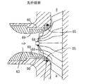
- the turbocharger with a sliding member includes a fresh air passage 63 that guides fresh air to the compressor impeller in the compressor housing, and a first intake / exhaust formed in a part of the wall of the compressor housing that faces the compressor impeller.
- the turbocharger includes an outlet 68, a second intake / exhaust port 69 facing a fresh air passage upstream from the compressor impeller, and a bypass passage 60 that allows the first and second intake / exhaust ports to communicate with each other at the blade edge of the compressor impeller.
- a sliding member 65 is mounted on at least a part of the opposing wall surface of the compressor housing.
- the centripetal compressor 71 includes a compressor housing 73 and a compressor wheel 74 having a compressor blade 75 mounted in the housing.
- the compressor housing 73 includes a cover plate 76 and a diffuser flange 79 fixed to both the cover plate and the bearing housing.
- the diffuser flange 79 includes an outer peripheral portion attached to the cover member and a radially inner portion attached to the bearing housing.
- a fragile groove is defined at an intermediate position between the outer peripheral edge portion and the radially inner portion, so that the diffuser flange can be expected to be destroyed when the compressor wheel is broken.
- the broken line is a presurge line
- abnormal noise high-frequency sound
- This high frequency sound may reach a sound pressure level of 90 dB or higher, and although the compressor performance itself does not deteriorate, measures are required as one of noise sources in passenger cars and the like that require quietness.
- This abnormal noise (high frequency sound) continues to be generated up to the surge point when the flow rate is reduced at the same rotation speed, and the abnormal noise disappears when the surge enters, and a surge noise (intermittent sound) is observed instead.
- this noise (high-frequency sound) can be reduced or eliminated by shifting the surge line to the small flow rate side with the compressor housing with a circulation path described above, but the compressor housing with a circulation path has a complicated structure. There is a problem that the manufacturing cost is higher than that of a compressor housing without a circulation path.
- an object of the present invention is to provide a compressor housing for a turbocharger that can significantly reduce or eliminate abnormal noise (high-frequency sound) generated from a pre-surge line to a surge line without providing a sound insulating material or a circulation path. There is to do.
- a turbocharger that rotationally drives a turbine impeller with exhaust gas of an internal combustion engine, transmits the rotational force to the compressor impeller, rotationally drives the turbocharger, and compresses air or an air-fuel mixture to be supplied to the internal combustion engine.
- Compressor housing for The compressor impeller has a plurality of long blades and short blades alternately arranged in the circumferential direction, The compressor housing has an annular groove on its inner surface that surrounds the vicinity of the leading edge tip portion of the short blade in the circumferential direction and is recessed outward, and does not communicate with the compressor inlet.
- a compressor housing is provided.
- the axial center of the annular groove is located within 5 mm in the axial direction on the upstream side or the downstream side of the leading edge tip portion of the short blade, and the axial groove width is The maximum diameter of the annular groove is less than 1.2 times the leading edge tip portion of the short blade.
- the annular groove extends from the inner surface of the compressor housing outward or perpendicularly or obliquely with respect to the rotation axis of the compressor.
- the inventors of the present invention found that the above-mentioned abnormal noise (high-frequency sound) is caused by the impeller's turning stall, and that the abnormal noise is generated by peeling and hitting the short blade. I found it.
- the present invention is based on such novel findings.
- the compressor housing has an annular groove on its inner surface that surrounds the vicinity of the front edge tip portion of the short blade in the circumferential direction and is recessed outward and does not communicate with the compressor inlet.
- the cross-sectional area of the flow path is rapidly expanded by this annular groove, and can be silenced. This silencing effect has been confirmed in examples described later.
- FIG. 6 is a cross-sectional view of the compressor housing portion of FIG. 5.
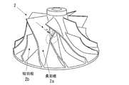
- FIG. 3 is a perspective view of a compressor impeller.
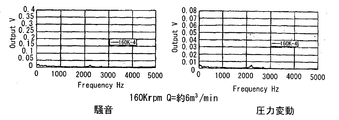
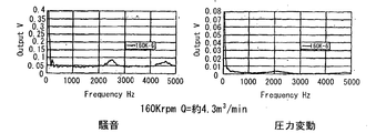
- test results of the conventional compressor housing in the case of a turbo rotation speed of 160,000 rpm and a flow rate of about 6 m 3 / min. These are the test results of a conventional compressor housing, in the case of a turbo rotation speed of 160,000 rpm and a flow rate of about 5 m 3 / min. These are the test results of a conventional compressor housing, in the case of a turbo rotation speed of 160,000 rpm and a flow rate of about 4.3 m 3 / min. These are the test results of the compressor housing of the present invention, in the case where the turbo rotation number is 160,000 rpm and the flow rate is about 6 m 3 / min.
- FIG. 3 is a view showing an original compressor housing. These show the 2nd Example of the compressor housing of this invention, and are the 2nd compressor housing by this invention. These show the 2nd Example of the compressor housing of this invention, and are the 3rd compressor housing by this invention.
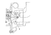
- FIG. 5 is an overall configuration diagram of a turbocharger including a compressor housing according to the present invention.
- the turbocharger rotationally drives the turbine impeller 1 with the exhaust gas of the internal combustion engine, transmits the rotational force to the compressor impeller 2 and rotationally drives it, and compresses air or an air-fuel mixture so as to supply it to the internal combustion engine. It has become.
- FIG. 6 is an enlarged cross-sectional view of the compressor housing portion of FIG. 5, and FIG. 7 is a perspective view of the compressor impeller 2.
- the compressor impeller 2 has a plurality of long blades 2a and short blades 2b that are alternately arranged in the circumferential direction.
- the compressor housing 10 of the present invention has an inner surface that surrounds the vicinity of the front edge tip portion of the short blade 2 b of the compressor impeller 2 in the circumferential direction and is recessed outward so as not to communicate with the suction port of the compressor.
- An annular groove 12 is provided.
- the axial center a of the annular groove 12 is located within 5 mm in the axial direction on the upstream side or downstream side of the leading edge tip portion of the short blade 2b. Further, the groove width b in the axial direction of the annular groove 12 is 2.5 mm or more and 10 mm or less. Further, the maximum diameter d of the annular groove 12 is preferably less than 1.2 times the leading edge tip portion of the short blade 2b.
- the annular groove 12 extends from the inner surface of the compressor housing 10 to the outside in a direction perpendicular to the rotation axis of the compressor, but may extend obliquely.
- the above-mentioned abnormal noise (high-frequency sound) was observed in the engine test. Therefore, an element performance test of a single turbo was conducted, and in this element test also, abnormal noise was reproduced at a turbo rotation speed of 160,000 rpm and 180,000 rpm, and the generated frequency was about 2.3 kHz, equivalent to that on the engine.
- the inventors of the present invention have found that the abnormal noise is caused by the impeller's rotational stall, and as shown schematically in FIG. It was discovered by an original study that the flaking that occurred at the point of growth grew and hit this short blade at the broken line in the figure.
- the reason for this is that the frequency of the abnormal noise does not depend on the primary rotation, the abnormal noise initial point coincides with the presurge point (inlet pressure fluctuation start point), and the compressor instability region (pressure rising upward) Characteristics), abnormal noise continues to occur, the compressor housing vibrates, and so on. Further, the reason why the noise generation frequency is as high as about 2.3 kHz is due to the characteristics of the impeller, and it was determined that the number of stalled cells (the number of stalled blades) was large. Based on the above-described novel findings, the inventors of the present invention prepared two types of compressor housings for the purpose of delaying stall, and conducted an element performance test of a single turbo.
- FIG. 8A is a view showing a first embodiment of the compressor housing of the present invention.
- FIG. 8A is a compressor housing according to the present invention
- FIG. 8B is a conventional compressor housing with a circulation path.
- the compressor housing 10 of the present invention is obtained by additionally processing an annular groove 12 on the inner surface of the compressor housing of the turbocharger in which abnormal noise (high-frequency sound) is observed.
- the axial center of the annular groove 12 is located 4 mm in the axial direction upstream of the leading edge tip portion of the short blade 2 b
- the axial groove width b of the annular groove 12 is 2.5 mm
- the depth c was 4 mm.
- the annular groove 12 extends from the inner surface of the compressor housing 10 to the outside in the example perpendicular to the rotation axis of the compressor.
- the conventional compressor housing with a circulation path has the same inner shape as the compressor housing of the turbocharger in which abnormal noise (high frequency sound) was observed, but was newly manufactured from a mold.
- the circulation path of the compressor housing is a circulation path that connects the same position as the compressor housing 10 of the present invention and the suction port of the compressor.
- the groove width b 'of the circulation path was 2.5 mm, and the groove width e of the outlet was 6 mm.
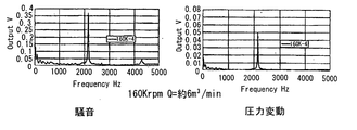
- FIG. 9A, 9B, and 9C are test results of a conventional compressor housing.
- FIG. 9A, FIG. 9B, and FIG. 9C show, in order, a turbo rotation speed of 160,000 rpm and a flow rate of about 6,5, 4.3 m 3 / min, the left side is a noise measurement value, and the right side is a pressure fluctuation measurement value. is there. From this figure, a strong peak occurs in both noise and pressure fluctuations in the vicinity of a turbo rotation speed of 160,000 rpm, a flow rate of about 6 m 3 / min, and a frequency of 2.3 kHz, which corresponds to the above-described abnormal noise (high-frequency sound). I understand.
- FIG. 10A, 10B, and 10C are test results of the compressor housing of the present invention.
- FIG. 10A, FIG. 10B, and FIG. 10C are, in order, a turbo rotation number of 160,000 rpm and a flow rate of about 6,5, 4.3 m 3 / min, respectively, a noise measurement value on the left side and a pressure fluctuation measurement value on the right side. is there. From this figure, noise and pressure fluctuation peaks hardly occur at the turbo rotation speed of 160,000 rpm, a flow rate of about 6 m 3 / min, and a frequency of 2.3 kHz, and the above-mentioned abnormal noise (high-frequency sound) is hardly generated. I understand that I do not.
- Table 1 shows the measurement results of the abnormal noise output at the abnormal noise initial point in this example.
- the conventional compressor housing that is, no noise countermeasure is “original”
- the compressor housing of the present invention is “annular grooved”
- another noise countermeasure “with circulation path” is a reference comparison. It is an example.
- FIG. 11B and 11C are views showing a second embodiment of the compressor housing of the present invention.
- 11A is the original compressor housing
- FIG. 11B is the second compressor housing according to the present invention
- FIG. 11C is the third compressor housing according to the present invention.
- the original turbocharger is different from that of the first embodiment.
- the diameters of d1 and d2 are 62 and 82 mm, respectively.
- the second compressor housing of FIG. 11B is obtained by additionally processing an annular groove 12 on the inner surface of the original compressor housing of FIG. 11A.
- the axial center of the annular groove 12 coincides with the leading edge tip portion of the short blade 2b
- the axial groove width b1 of the annular groove 12 is 3.5 mm
- the outer diameter d3 of the annular groove 12 is 80 mm.
- the annular groove 12 extends outward from the inner surface of the compressor housing 10, in this example, in the upstream direction inclined by 60 degrees with respect to the rotation axis of the compressor.
- 11C has an annular cavity having an inner diameter (d4) of 75 mm, an outer diameter (d5) of 90 mm, and a length (b2) of 22.5 mm outside the annular groove 12 of the second compressor housing of FIG. 11B. It is provided.
- FIG. 11A, FIG. 11B, and FIG. 11C were tested for a turbocharger.
- the surge flow rate was about 8.4 m 3 / min in the original of FIG. up to about 7.7 m 3 / min, it could be reduced to about 7.6 m 3 / min in Figure 11C. Therefore, this result also shows that the surge line can be lowered and the abnormal noise output can be similarly reduced by the compressor housing of the present invention including FIGS. 11B and 11C.
- the compressor housing 10 has an annular groove on the inner surface thereof that surrounds the vicinity of the front edge tip portion of the short blade in the circumferential direction and is recessed outwardly so as not to communicate with the suction port of the compressor. 12, the annular groove 12 rapidly expands the cross-sectional area of the flow path, can be silenced, and generates abnormal noise (high-frequency sound) from the pre-surge line to the surge line without providing a sound insulating material or a circulation path. ) Can be greatly reduced or eliminated.
Landscapes
- Engineering & Computer Science (AREA)
- Mechanical Engineering (AREA)
- General Engineering & Computer Science (AREA)
- Supercharger (AREA)
- Structures Of Non-Positive Displacement Pumps (AREA)
Abstract
Description
本発明は、異音(高周波音)を低減するターボチャージャ用のコンプレッサハウジングに関する。
内燃機関のシリンダに供給される空気或いは混合気をあらかじめ圧縮することを過給といい、その圧縮機を過給機という。また、そのうち機関の排気ガスを利用して過給を行う過給機を排気タービン過給機、または単にターボチャージャという。
ベアリングハウジング53、タービンハウジング54、コンプレッサハウジング55a及びシールプレート55bは図示の順序で互いに連結されている。また、タービンロータ軸51は、タービンインペラ51aとロータ軸51bが溶接等で一体化されており、ベアリングハウジング53で回転支持され、コンプレッサインペラ52に同軸に連結されている。
従って、ターボチャージャを備えたエンジンの作動線は、この図に示すようにサージラインから十分離して設定される。
かかる循環経路付きコンプレッサハウジングは、例えば特許文献1、2に開示されている。
図3に示すように、この滑り部材付きターボチャージャは、コンプレッサハウジング内のコンプレッサインペラへ新気を導く新気通路63と、コンプレッサインペラに対向するコンプレッサハウジング壁面の一部に形成される第1吸排出口68と、コンプレッサインペラより上流の新気通路に臨む第2吸排出口69と、第1及び第2吸排出口を連通させるバイパス通路60とを備えたターボチャージャであり、コンプレッサインペラのブレード縁部に対向する前記コンプレッサハウジング壁面の少なくとも一部に滑り部材65を装着したことを特徴とする。
図4に示すように、求心コンプレッサ71は、コンプレッサハウジング73と、このハウジング内に装着されるコンプレッサブレード75を備えたコンプレッサホイール74とを含む。コンプレッサハウジング73は、カバープレート76と、このカバープレートおよび軸受ハウジングの双方に固定されるディフューザフランジ79とを含む。ディフューザフランジ79は、カバー部材に取着される外側周縁部分と、軸受ハウジングに取着される半径方向内側部分とを含む。ディフューザにはその外側周縁部分と半径方向内側部分との中間位置に壊れ易い溝部が画定されていて、これにより、コンプレッサホイールの破損時におけるディフューザフランジの予期破壊が可能とされている。
この異音(高周波音)は同一回転速度において流量が少なくなるとサージ点まで発生し続け、サージ突入時には異音が消え、代わってサージ音(間欠音)が観測される。
前記コンプレッサインペラは、周方向に交互に配置されたそれぞれ複数の長羽根と短羽根を有し、
前記コンプレッサハウジングは、その内面に、前記短羽根の前縁チップ部近傍を周方向に囲んで外方に凹み、コンプレッサの吸入口と連通しない環状溝を有する、ことを特徴とするターボチャージャ用のコンプレッサハウジングが提供される。
なおこの消音効果は、後述する実施例で確認されている。
このターボチャージャは、内燃機関の排気ガスでタービンインペラ1を回転駆動し、その回転力をコンプレッサインペラ2に伝達してこれを回転駆動し、空気又は混合気を圧縮して内燃機関に供給するようになっている。
図7に示すように、本発明において、コンプレッサインペラ2は、周方向に交互に配置されたそれぞれ複数の長羽根2aと短羽根2bを有する。
本発明のコンプレッサハウジング10は、図6に示すように、その内面に、コンプレッサインペラ2の短羽根2bの前縁チップ部近傍を周方向に囲んで外方に凹み、コンプレッサの吸入口と連通しない環状溝12を有する。
本発明の発明者らは、異音の発生要因は、インペラの旋回失速によるものであり、図7に圧縮される流体の流れの状態を模式的に示すように、長羽根の入口、チップ近傍で発生した剥離が成長して図の破線部で短羽根に当たってこの異音が発生することを独自の検討により見出した。
その根拠は、異音の周波数が回転1次には依存していない、異音初生点がプレサージ点(入口部圧力変動開始点)と一致している、コンプレッサの不安定領域(右上がりの圧力特性)で異音が発生し続けている、コンプレッサハウジングが振動している、等に基づいている。
また、異音の発生周波数が約2.3kHzと高い要因は、インペラの特性によるもので、失速セル数(失速している羽根枚数)が多いためと判断した。
上述した新規の知見に基づき、本発明の発明者らは、失速を遅延させる目的で2種のコンプレッサハウジングを準備し、ターボ単体の要素性能試験を実施した。
本発明のコンプレッサハウジング10は、異音(高周波音)が観測された上記ターボチャージャのコンプレッサハウジングの内面に、環状溝12を追加工したものである。
この例で、環状溝12の軸方向中心は、短羽根2bの前縁チップ部の上流側に軸方向4mmに位置し、環状溝12の軸方向の溝幅bは2.5mm、環状溝12の深さcは4mmとした。また、環状溝12は、コンプレッサハウジング10の内面から外方にコンプレッサの回転軸に対してこの例では垂直に延びる。
この図から、ターボ回転数16万rpm、流量約6m3/min、周波数2.3kHz付近において、騒音、圧力変動とも強いピークが発生しており、上述した異音(高周波音)に相当することがわかる。
この図から、ターボ回転数16万rpm、流量約6m3/min、周波数2.3kHz付近において、騒音、圧力変動のピークはほとんど発生しておらず、上述した異音(高周波音)がほとんど発生しないことがわかる。
この表において、従来のコンプレッサハウジングつまり異音対策無しは、「オリジナル」であり、本発明のコンプレッサハウジングは「環状溝付」であり、別の異音対策である「循環経路付」は参考比較例である。

なお、参考比較例の循環経路付でも、同様の効果は得られるが、循環経路付きコンプレッサハウジングは、構造が複雑であり、循環経路のないコンプレッサハウジングに比較して製造コストが高いため、本発明の目的は達成できない。
オリジナルのターボチャージャは、実施例1とは別のものであり、この図でd1,d2の直径がそれぞれ62、82mmのものである。
図11Bの第2のコンプレッサハウジングは、図11Aのオリジナルのコンプレッサハウジングの内面に、環状溝12を追加工したものである。
この例で、環状溝12の軸方向中心は、短羽根2bの前縁チップ部と一致し、環状溝12の軸方向の溝幅b1は3.5mm、環状溝12の外径d3は80mmとした。また、環状溝12は、コンプレッサハウジング10の内面から外方に、この例では、コンプレッサの回転軸に対して60度傾いた上流側方向に延びている。
図11Cの第3のコンプレッサハウジングは、図11Bの第2コンプレッサハウジングの環状溝12の外側に、内径(d4)75mm、外径(d5)90mm、長さ(b2)22.5mmの環状空洞を設けたものである。
従って、この結果からも、図11B、図11Cを含む本発明のコンプレッサハウジングによって、サージラインを下げることができ、異音出力も同様に低減できることがわかる。
Claims (3)
- 内燃機関の排気ガスでタービンインペラを回転駆動し、その回転力をコンプレッサインペラに伝達してこれを回転駆動し、空気又は混合気を圧縮して内燃機関に供給するターボチャージャ用のコンプレッサハウジングであって、
前記コンプレッサインペラは、周方向に交互に配置されたそれぞれ複数の長羽根と短羽根を有し、
前記コンプレッサハウジングは、その内面に、前記短羽根の前縁チップ部近傍を周方向に囲んで外方に凹み、コンプレッサの吸入口と連通しない環状溝を有する、ことを特徴とするターボチャージャ用のコンプレッサハウジング。 - 前記環状溝の軸方向中心は、前記短羽根の前縁チップ部の上流側又は下流側に軸方向5mm以内に位置し、その軸方向の溝幅は、2.5mm以上、10mm以下であり、環状溝の最大径は前記短羽根の前縁チップ部の1.2倍未満である、ことを特徴とする請求項1に記載のターボチャージャ用のコンプレッサハウジング。
- 前記環状溝は、コンプレッサハウジングの内面から外方にコンプレッサの回転軸に対して垂直又は斜めに延びる、ことを特徴とする請求項1に記載のターボチャージャ用のコンプレッサハウジング。
Priority Applications (5)
| Application Number | Priority Date | Filing Date | Title |
|---|---|---|---|
| EP08777250A EP2290205A1 (en) | 2008-06-17 | 2008-06-17 | Compressor housing for turbo charger |
| PCT/JP2008/061012 WO2009153854A1 (ja) | 2008-06-17 | 2008-06-17 | ターボチャージャ用のコンプレッサハウジング |
| KR1020107020044A KR20100119565A (ko) | 2008-06-17 | 2008-06-17 | 터보차저용 컴프레서 하우징 |
| US12/999,931 US20110091323A1 (en) | 2008-06-17 | 2008-06-17 | Compressor housing for turbocharger |
| CN2008801299776A CN102066717A (zh) | 2008-06-17 | 2008-06-17 | 涡轮增压机用的压缩机壳体 |
Applications Claiming Priority (1)
| Application Number | Priority Date | Filing Date | Title |
|---|---|---|---|
| PCT/JP2008/061012 WO2009153854A1 (ja) | 2008-06-17 | 2008-06-17 | ターボチャージャ用のコンプレッサハウジング |
Publications (1)
| Publication Number | Publication Date |
|---|---|
| WO2009153854A1 true WO2009153854A1 (ja) | 2009-12-23 |
Family
ID=41433785
Family Applications (1)
| Application Number | Title | Priority Date | Filing Date |
|---|---|---|---|
| PCT/JP2008/061012 WO2009153854A1 (ja) | 2008-06-17 | 2008-06-17 | ターボチャージャ用のコンプレッサハウジング |
Country Status (5)
| Country | Link |
|---|---|
| US (1) | US20110091323A1 (ja) |
| EP (1) | EP2290205A1 (ja) |
| KR (1) | KR20100119565A (ja) |
| CN (1) | CN102066717A (ja) |
| WO (1) | WO2009153854A1 (ja) |
Cited By (3)
| Publication number | Priority date | Publication date | Assignee | Title |
|---|---|---|---|---|
| JP2013527382A (ja) * | 2010-06-04 | 2013-06-27 | ボーグワーナー インコーポレーテッド | 排気ガスターボチャージャのコンプレッサ |
| WO2019172238A1 (ja) * | 2018-03-05 | 2019-09-12 | いすゞ自動車株式会社 | ターボ式過給機、ターボ式過給システム及びターボ式過給システムの過給方法 |
| CN112443515A (zh) * | 2019-09-03 | 2021-03-05 | 盖瑞特交通一公司 | 具有用于流动再循环的带端口护罩和噪声衰减器的压缩机以及包含该压缩机的涡轮增压器 |
Families Citing this family (18)
| Publication number | Priority date | Publication date | Assignee | Title |
|---|---|---|---|---|
| WO2007148390A1 (ja) * | 2006-06-21 | 2007-12-27 | Ihi Corporation | 回転機械の軸受構造、回転機械、軸受構造の製造方法、並びに回転機械の製造方法 |
| JP5853721B2 (ja) * | 2012-01-23 | 2016-02-09 | 株式会社Ihi | 遠心圧縮機 |
| DE112013001507T5 (de) * | 2012-04-23 | 2015-03-19 | Borgwarner Inc. | Turboladerschaufel mit Umrisskantenstufe und Turbolader, der sie enthält |
| WO2013162896A1 (en) * | 2012-04-23 | 2013-10-31 | Borgwarner Inc. | Turbocharger shroud with cross-wise grooves and turbocharger incorporating the same |
| RU2014145610A (ru) | 2012-04-23 | 2016-06-10 | Боргварнер Инк. | Ступица турбины с несплошностью поверхности и турбонагнетатель, содержащий такую ступицу |
| IN2015DN00342A (ja) * | 2012-06-25 | 2015-06-12 | Borgwarner Inc | |
| DE112013003306B4 (de) * | 2012-07-26 | 2023-04-06 | Borgwarner Inc. | Verdichterabdeckung mit Umfangsnut |
| EP3032109B1 (en) * | 2013-08-06 | 2018-06-13 | IHI Corporation | Centrifugal compressor and supercharger |
| DE102013018286A1 (de) * | 2013-10-31 | 2015-04-30 | Man Diesel & Turbo Se | Radialverdichter |
| DE102013020826A1 (de) | 2013-12-17 | 2015-06-18 | Man Diesel & Turbo Se | Radialverdichterstufe |
| KR20150114384A (ko) * | 2014-04-01 | 2015-10-12 | (주)계양정밀 | 소음저감장치를 갖는 터보차저 |
| JP6369621B2 (ja) * | 2015-02-18 | 2018-08-08 | 株式会社Ihi | 遠心圧縮機および過給機 |
| US10563515B2 (en) * | 2015-03-26 | 2020-02-18 | Mitsubishi Heavy Industries Engine & Turbocharger, Ltd. | Turbine impeller and variable geometry turbine |
| WO2017150254A1 (ja) * | 2016-03-03 | 2017-09-08 | 株式会社Ihi | 回転機械 |
| KR20190075514A (ko) | 2017-12-21 | 2019-07-01 | 주식회사 포스코 | 압연 소재의 평탄도 제어 장치 및 이를 이용한 제어 방법 |
| DE102018132978A1 (de) * | 2018-12-19 | 2020-06-25 | Ebm-Papst Mulfingen Gmbh & Co. Kg | Turboverdichter mit angepasster Meridiankontur der Schaufeln und Verdichterwand |
| KR20200124375A (ko) * | 2019-04-23 | 2020-11-03 | 현대자동차주식회사 | 터보차저 컴프레서휠 |
| KR20210056086A (ko) | 2019-11-08 | 2021-05-18 | 현대위아 주식회사 | 차량용 터보차저 |
Citations (5)
| Publication number | Priority date | Publication date | Assignee | Title |
|---|---|---|---|---|
| JPH11173153A (ja) | 1997-12-10 | 1999-06-29 | Kyoritsu:Kk | 滑り部材付きターボチャージャ |
| JPH11190297A (ja) | 1997-10-10 | 1999-07-13 | Holset Eng Co Ltd | コンプレッサおよびタービンの内部またはこれに関連する改良 |
| JP2000064848A (ja) * | 1998-08-21 | 2000-02-29 | Ishikawajima Harima Heavy Ind Co Ltd | ターボチャージャ |
| JP2003343486A (ja) * | 2002-05-28 | 2003-12-03 | Ishikawajima Harima Heavy Ind Co Ltd | 長短羽根車を備えた遠心圧縮機 |
| JP2004144029A (ja) * | 2002-10-25 | 2004-05-20 | Toyota Central Res & Dev Lab Inc | ターボチャージャ用遠心圧縮機 |
Family Cites Families (6)
| Publication number | Priority date | Publication date | Assignee | Title |
|---|---|---|---|---|
| US4212585A (en) * | 1978-01-20 | 1980-07-15 | Northern Research And Engineering Corporation | Centrifugal compressor |
| US4930978A (en) * | 1988-07-01 | 1990-06-05 | Household Manufacturing, Inc. | Compressor stage with multiple vented inducer shroud |
| CZ48394A3 (en) * | 1993-03-04 | 1994-09-14 | Abb Management Ag | Radial-flow compressor with a flow-stabilizing casing |
| US6231301B1 (en) * | 1998-12-10 | 2001-05-15 | United Technologies Corporation | Casing treatment for a fluid compressor |
| EP1247991B1 (en) * | 2001-04-05 | 2005-10-12 | Hitachi, Ltd. | Centrifugal pump |
| US7575411B2 (en) * | 2006-05-22 | 2009-08-18 | International Engine Intellectual Property Company Llc | Engine intake air compressor having multiple inlets and method |
-
2008
- 2008-06-17 KR KR1020107020044A patent/KR20100119565A/ko not_active Application Discontinuation
- 2008-06-17 WO PCT/JP2008/061012 patent/WO2009153854A1/ja active Application Filing
- 2008-06-17 EP EP08777250A patent/EP2290205A1/en not_active Withdrawn
- 2008-06-17 CN CN2008801299776A patent/CN102066717A/zh active Pending
- 2008-06-17 US US12/999,931 patent/US20110091323A1/en not_active Abandoned
Patent Citations (5)
| Publication number | Priority date | Publication date | Assignee | Title |
|---|---|---|---|---|
| JPH11190297A (ja) | 1997-10-10 | 1999-07-13 | Holset Eng Co Ltd | コンプレッサおよびタービンの内部またはこれに関連する改良 |
| JPH11173153A (ja) | 1997-12-10 | 1999-06-29 | Kyoritsu:Kk | 滑り部材付きターボチャージャ |
| JP2000064848A (ja) * | 1998-08-21 | 2000-02-29 | Ishikawajima Harima Heavy Ind Co Ltd | ターボチャージャ |
| JP2003343486A (ja) * | 2002-05-28 | 2003-12-03 | Ishikawajima Harima Heavy Ind Co Ltd | 長短羽根車を備えた遠心圧縮機 |
| JP2004144029A (ja) * | 2002-10-25 | 2004-05-20 | Toyota Central Res & Dev Lab Inc | ターボチャージャ用遠心圧縮機 |
Cited By (3)
| Publication number | Priority date | Publication date | Assignee | Title |
|---|---|---|---|---|
| JP2013527382A (ja) * | 2010-06-04 | 2013-06-27 | ボーグワーナー インコーポレーテッド | 排気ガスターボチャージャのコンプレッサ |
| WO2019172238A1 (ja) * | 2018-03-05 | 2019-09-12 | いすゞ自動車株式会社 | ターボ式過給機、ターボ式過給システム及びターボ式過給システムの過給方法 |
| CN112443515A (zh) * | 2019-09-03 | 2021-03-05 | 盖瑞特交通一公司 | 具有用于流动再循环的带端口护罩和噪声衰减器的压缩机以及包含该压缩机的涡轮增压器 |
Also Published As
| Publication number | Publication date |
|---|---|
| EP2290205A1 (en) | 2011-03-02 |
| US20110091323A1 (en) | 2011-04-21 |
| KR20100119565A (ko) | 2010-11-09 |
| CN102066717A (zh) | 2011-05-18 |
Similar Documents
| Publication | Publication Date | Title |
|---|---|---|
| WO2009153854A1 (ja) | ターボチャージャ用のコンプレッサハウジング | |
| JP4247214B2 (ja) | 排気タービン過給機 | |
| US8157516B2 (en) | Compressor wheel housing | |
| US7942625B2 (en) | Compressor and compressor housing | |
| US7575411B2 (en) | Engine intake air compressor having multiple inlets and method | |
| JPWO2014030248A1 (ja) | 遠心圧縮機 | |
| JP5369723B2 (ja) | 遠心圧縮機 | |
| JP6326912B2 (ja) | 可変ノズルユニット及び可変容量型過給機 | |
| US6792755B2 (en) | High-pressure ratio turbocharger | |
| WO2018146753A1 (ja) | 遠心圧縮機、ターボチャージャ | |
| JP2010270641A (ja) | 遠心圧縮機 | |
| JP2010270732A (ja) | インペラ及び過給機 | |
| JP2011111988A (ja) | 過給エンジンシステム | |
| JP2012002140A (ja) | タービン及び過給機 | |
| US6920754B2 (en) | High-pressure ratio turbocharger | |
| JP2004027931A (ja) | 遠心圧縮機 | |
| JP2009221984A (ja) | 遠心圧縮機 | |
| JPH07332273A (ja) | コンプレッサのケーシング構造 | |
| JP5863720B2 (ja) | 過給機用サイレンサ | |
| JP2015031237A (ja) | 可変ノズルユニット及び可変容量型過給機 | |
| JP2008240713A (ja) | ターボチャージャ用のコンプレッサハウジング | |
| US20150159547A1 (en) | Cross Flow Turbine | |
| JP2014234803A (ja) | 可変容量型タービン及び可変容量型過給機 | |
| JP2014240612A (ja) | 遠心圧縮機及び過給機 | |
| JP2014234713A (ja) | ラジアルタービン及び過給機 |
Legal Events
| Date | Code | Title | Description |
|---|---|---|---|
| WWE | Wipo information: entry into national phase |
Ref document number: 200880129977.6 Country of ref document: CN |
|
| 121 | Ep: the epo has been informed by wipo that ep was designated in this application |
Ref document number: 08777250 Country of ref document: EP Kind code of ref document: A1 |
|
| WWE | Wipo information: entry into national phase |
Ref document number: 2008777250 Country of ref document: EP |
|
| ENP | Entry into the national phase |
Ref document number: 20107020044 Country of ref document: KR Kind code of ref document: A |
|
| WWE | Wipo information: entry into national phase |
Ref document number: 8222/CHENP/2010 Country of ref document: IN |
|
| WWE | Wipo information: entry into national phase |
Ref document number: 12999931 Country of ref document: US |
|
| NENP | Non-entry into the national phase |
Ref country code: DE |
|
| NENP | Non-entry into the national phase |
Ref country code: JP |