WO2009145264A1 - 通信機器 - Google Patents
通信機器 Download PDFInfo
- Publication number
- WO2009145264A1 WO2009145264A1 PCT/JP2009/059790 JP2009059790W WO2009145264A1 WO 2009145264 A1 WO2009145264 A1 WO 2009145264A1 JP 2009059790 W JP2009059790 W JP 2009059790W WO 2009145264 A1 WO2009145264 A1 WO 2009145264A1
- Authority
- WO
- WIPO (PCT)
- Prior art keywords
- frequency band
- antenna
- intensity
- communication device
- adjustment
- Prior art date
- Legal status (The legal status is an assumption and is not a legal conclusion. Google has not performed a legal analysis and makes no representation as to the accuracy of the status listed.)
- Ceased
Links
Images





Classifications
-
- H—ELECTRICITY
- H04—ELECTRIC COMMUNICATION TECHNIQUE
- H04M—TELEPHONIC COMMUNICATION
- H04M1/00—Substation equipment, e.g. for use by subscribers
- H04M1/02—Constructional features of telephone sets
- H04M1/0202—Portable telephone sets, e.g. cordless phones, mobile phones or bar type handsets
- H04M1/0206—Portable telephones comprising a plurality of mechanically joined movable body parts, e.g. hinged housings
- H04M1/0208—Portable telephones comprising a plurality of mechanically joined movable body parts, e.g. hinged housings characterized by the relative motions of the body parts
- H04M1/0214—Foldable telephones, i.e. with body parts pivoting to an open position around an axis parallel to the plane they define in closed position
-
- H—ELECTRICITY
- H01—ELECTRIC ELEMENTS
- H01Q—ANTENNAS, i.e. RADIO AERIALS
- H01Q1/00—Details of, or arrangements associated with, antennas
- H01Q1/12—Supports; Mounting means
- H01Q1/22—Supports; Mounting means by structural association with other equipment or articles
- H01Q1/24—Supports; Mounting means by structural association with other equipment or articles with receiving set
- H01Q1/241—Supports; Mounting means by structural association with other equipment or articles with receiving set used in mobile communications, e.g. GSM
- H01Q1/242—Supports; Mounting means by structural association with other equipment or articles with receiving set used in mobile communications, e.g. GSM specially adapted for hand-held use
- H01Q1/243—Supports; Mounting means by structural association with other equipment or articles with receiving set used in mobile communications, e.g. GSM specially adapted for hand-held use with built-in antennas
-
- H—ELECTRICITY
- H01—ELECTRIC ELEMENTS
- H01Q—ANTENNAS, i.e. RADIO AERIALS
- H01Q21/00—Antenna arrays or systems
- H01Q21/29—Combinations of different interacting antenna units for giving a desired directional characteristic
-
- H—ELECTRICITY
- H01—ELECTRIC ELEMENTS
- H01Q—ANTENNAS, i.e. RADIO AERIALS
- H01Q21/00—Antenna arrays or systems
- H01Q21/30—Combinations of separate antenna units operating in different wavebands and connected to a common feeder system
-
- H—ELECTRICITY
- H01—ELECTRIC ELEMENTS
- H01Q—ANTENNAS, i.e. RADIO AERIALS
- H01Q7/00—Loop antennas with a substantially uniform current distribution around the loop and having a directional radiation pattern in a plane perpendicular to the plane of the loop
- H01Q7/005—Loop antennas with a substantially uniform current distribution around the loop and having a directional radiation pattern in a plane perpendicular to the plane of the loop with variable reactance for tuning the antenna
-
- H—ELECTRICITY
- H04—ELECTRIC COMMUNICATION TECHNIQUE
- H04M—TELEPHONIC COMMUNICATION
- H04M1/00—Substation equipment, e.g. for use by subscribers
- H04M1/02—Constructional features of telephone sets
- H04M1/0202—Portable telephone sets, e.g. cordless phones, mobile phones or bar type handsets
- H04M1/026—Details of the structure or mounting of specific components
Definitions
- the present invention relates to a communication device having an antenna.
- first casing as an operation unit provided for operation by a user
- second casing as a display provided for display of various information.
- the mainstream is one that is connected by a hinge mechanism and configured to be relatively movable between an open state and a closed state about the rotation axis of the hinge mechanism.
- the main antenna for call / data communication is arranged at one end of the first casing or one end of the second casing.
- the reference potential (GND) of the entire device is stabilized at a high frequency to prevent deterioration of the gain of the main antenna.
- the communication terminal according to Patent Document 1 is compared with the closed state in which the first housing, the second housing, and the first housing and the second housing are overlaid. And a connecting portion that connects the first housing and the second housing so as to be movable between an open state where the degree of overlapping is small, and is disposed in the first housing and the second housing.
- a conductor portion (circuit board) and a first antenna disposed in the vicinity of the connecting portion. In order to capacitively couple the conductor portion in the first housing and the conductor portion in the second housing, the distance between them is set to a predetermined distance L or less.
- the distance between them needs to be equal to or less than the predetermined distance L. For this reason, the degree of freedom is limited in designing the communication terminal.
- the present invention has been made in view of the above-described problems, and one of its purposes is a communication device capable of improving the gain of the first antenna while reducing a design impediment to freedom. Is to provide.
- the communication device includes a first casing, a second casing, and the first casing and the second casing that overlap each other.
- a connecting portion that connects the first housing and the second housing so as to be movable between a closed state and an open state in which the overlapping degree is smaller than the closed state;
- a signal line that electrically connects the conductive part and at least one of the first casing and the second casing, and the first conductive part or the second conductive part Disposed in at least one of the first antenna and the second casing electrically connected to the first antenna, and the first antenna And having a second antenna coupled capacitance of the conductive portion or the second conductive portion.
- the first antenna is configured to transmit or receive a signal related to a first frequency band, and a higher-order subordinate of the second antenna.
- the next resonance point is preferably included in the first frequency band.
- the first antenna is configured to transmit or receive a signal related to a first frequency band
- the second antenna is a higher-order signal.
- the secondary resonance point is configured to transmit or receive a signal related to a second frequency band that is not included in the first frequency band, and includes an adjusting unit that adjusts the second frequency band, and the adjustment
- the means adjusts the second frequency band so that a higher-order resonance point of the second antenna is included in the first frequency band.
- the communication device further includes a detection unit that detects the open state, and the adjustment unit detects the second antenna when the detection unit detects the open state. It is preferable to adjust the second frequency band so that a higher-order resonance point is included in the first frequency band.
- the communication device includes a detection unit that detects the closed state, and the adjustment unit suppresses the adjustment when the detection unit detects the closed state. Is preferred.
- a first control means for performing a first predetermined control based on a signal related to a first frequency band transmitted or received by the first antenna.
- the adjusting means is configured such that when the first predetermined control is performed by the first control means, a higher-order resonance point of the second antenna is included in the first frequency band. It is preferable to adjust the second frequency band.
- the adjustment unit suppresses the adjustment when the first predetermined control is suppressed by the first control unit.
- the communication device in the communication device of (3), includes a first intensity measuring unit that measures the intensity of a signal related to the first frequency band transmitted or received by the first antenna,
- the adjusting means is configured so that when the first intensity measuring means measures an intensity greater than a predetermined value, a higher-order resonance point of the second antenna is included in the first frequency band. It is preferable to adjust the frequency band of 2.
- the adjustment unit suppresses the adjustment when an intensity having a value smaller than a predetermined value is measured by the first intensity measurement unit.
- the communication device in the communication device of (3), includes a first intensity measuring unit that measures the intensity of a signal related to the first frequency band transmitted or received by the first antenna,
- the adjusting means may be arranged such that when the intensity of a value smaller than a predetermined value is measured by the first intensity measuring means, a higher-order resonance point of the second antenna is included in the first frequency band. It is preferable to adjust the frequency band of 2.
- the adjustment unit suppresses the adjustment when the intensity of a value equal to or greater than a predetermined value is measured by the first intensity measurement unit.
- second control means for performing a second predetermined control based on a signal related to a second frequency band transmitted or received by the second antenna
- the adjustment means has a higher-order resonance point of the second antenna in the first frequency band in a state where the second predetermined control by the second control means is not performed. It is preferable to adjust the second frequency band so as to be included.
- the adjustment unit may suppress the adjustment in a state where the second predetermined control by the second control unit is performed. preferable.
- the communication device includes a second intensity measuring unit that measures the intensity of a signal related to the second frequency band transmitted or received by the second antenna,
- the adjusting means may be arranged such that when the intensity of a value smaller than a predetermined value is measured by the second intensity measuring means, a higher-order resonance point of the second antenna is included in the first frequency band. It is preferable to adjust the frequency band of 2.
- the adjustment unit suppresses the adjustment when the second intensity measurement unit measures an intensity of a value greater than or equal to a predetermined value.
- the communication device in the communication device of (3), includes a second intensity measuring unit that measures the intensity of a signal related to the second frequency band transmitted or received by the second antenna,
- the adjusting means is configured so that a higher-order resonance point of the second antenna is included in the first frequency band when an intensity having a value larger than a predetermined value is measured by the second intensity measuring means. It is preferable to adjust the frequency band of 2.
- the adjustment unit suppresses the adjustment when the second intensity measurement unit measures an intensity of a value equal to or less than a predetermined value.
- the first antenna is disposed in the first casing.
- the present invention it is possible to improve the gain of the main antenna while reducing the obstruction factor of the degree of freedom of design.
- FIG. 1 is an external perspective view of a mobile phone device 1 according to the present invention. It is a figure which shows the perspective view of the state which folded the mobile telephone apparatus.
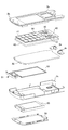
- FIG. 6 is an exploded perspective view of a member built in the operation unit side body unit 2.
- FIG. 6 is an exploded perspective view of members built in the display unit side body 3.
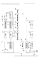
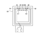
- It is a block diagram which shows the function of the mobile telephone apparatus 1 which concerns on this invention. It is a figure which shows the 1st structure of the magnetic field antenna 53 with which the mobile telephone apparatus 1 which concerns on this invention is equipped. It is a figure which shows the 2nd structure of the magnetic field antenna 53 with which the mobile telephone apparatus 1 which concerns on this invention is equipped.
- FIG. 9 is a cross-sectional view of the cellular phone device 1 shown in FIG. 8 taken along line AA.
- a mobile phone will be described as an example of a communication device.
- the present invention is not limited to this, and PHS (Personal Handy phone System: registered trademark), PDA (Personal Digital Assistant), portable navigation device, Other communication devices equipped with an antenna such as a notebook computer may be used.
- PHS Personal Handy phone System: registered trademark
- PDA Personal Digital Assistant
- portable navigation device Other communication devices equipped with an antenna such as a notebook computer may be used.
- FIG. 1 is an external perspective view of a mobile phone device 1 which is an example of a communication device according to the present invention that communicates with a host device.
- FIG. 2 shows a perspective view of the cellular phone device 1 in a folded state.
- the mobile phone device 1 has an operation unit side housing 2 (a second panel) having a front panel 2a, a front case 2b, a rear case 2c, and a rear panel 2d (not shown).
- Casing and a display unit side casing 3 (first casing) having a front panel 3a, a front case 3b, a rear case 3c, and a rear panel 3d.
- the operation unit side body unit 2 is configured such that an operation button group 11 and a voice input unit 12 to which a voice uttered by a user of the mobile phone device 1 is input are exposed on the surface of the front panel 2a. Is done.
- the operation button group 11 includes a function setting operation button 13 for operating various functions such as various settings, a telephone book function, and a mail function, and an input operation for inputting a telephone number and characters such as mail.
- the button 14 and a determination operation button 15 for performing determination and scrolling in various operations are configured.
- a cap that covers an interface for communicating with an external device (for example, a host device) is provided on the side surface of the operation unit side body unit 2.
- the display unit side body unit 3 is configured such that a display 21 for displaying various information and a receiver 22 for outputting the voice of the other party of the call are exposed on the front panel 3a.
- the upper end of the operation unit side body 2 and the lower end of the display unit side body 3 are connected via a hinge mechanism 4 (connection unit).
- the mobile phone device 1 moves the operation unit side body 2 and the display unit side body 3 connected via the hinge mechanism 4 relatively, thereby moving the surface of the operation unit side body 2. And the surface of the display unit side body 3 facing each other and folded (the first state and the open state overlapping each other), or the surface of the operation unit side body 2 and the display unit side body 3 And the surface of each of the two are exposed to the outside and opened to each other (a second state in which the degree of overlapping is smaller than the folded state, an open state).
- the foldable mobile phone device 1 using the hinge mechanism 4 is described.
- the foldable mobile phone device 1 is not foldable.
- the operation unit side body unit 2 includes, on one side, a side key 30 to which a predetermined function is assigned, an interface cap 31 in which external memory is inserted and removed, It has.
- the display unit side body 3 is provided with a slide key 32, which will be described in detail later, on one side surface.
- a camera 33 that captures an image of a subject and a light 34 that irradiates the subject with light are exposed on the surface of the rear panel 3d of the display unit side body 3.
- the camera 33 and the light 34 constitute a camera module.
- FIG. 3 is an exploded perspective view of members built in the operation unit side body 2.
- the operation unit side body 2 includes a front panel 2a, a front case 2b (in this figure, the front panel 2a and the front case 2b are coupled), and the operation button group described above. 11, a printed wiring board 50 (second conductive portion) including various electronic components such as a reference potential pattern layer and an RF (Radio Frequency) module, and hinge mechanisms 4a and 4b.
- a main antenna 51 first antenna
- a magnetic field antenna 53 second antenna
- rear case 2c a rear case 2c
- a rear panel 2d that protects the rechargeable battery 60.
- the front case 2b, the key sheet 40, the printed circuit board 50, and the rear case 2c are stacked. Moreover, the rechargeable battery 60 is accommodated so that it can be inserted and removed from the outside of the rear panel 2d.
- the front case 2b and the rear case 2c are arranged so that their concave inner surfaces face each other, and are joined so that their outer peripheral edges overlap each other. Further, the key sheet 40 and the printed circuit board 50 are built in between the front case 2b and the rear case 2c. That is, the key sheet 40 is laminated on the upper surface of the printed board 50.
- the flexible wiring board 45 has a plurality of key switches on the surface on the front panel 2a side, and each key switch has a structure having a metal dome of a metal plate that is curved in a bowl shape and is three-dimensionally formed. Yes. When the apex of the bowl-shaped shape is pressed, the metal dome comes into contact with a switch terminal formed in an electric circuit (not shown) printed on the surface of the flexible wiring board 45 and becomes electrically conductive.
- the flexible wiring board 45 is obtained by sandwiching wiring between a plurality of insulating films.
- various electronic components are arranged on the printed circuit board 50.
- Various electronic components form a plurality of circuit blocks by a predetermined combination.
- various circuit blocks including a wireless circuit, a power supply circuit, a digital circuit, and the like are formed.
- a plurality of key holes are formed on the inner surface of the front panel 2a facing the display 21 of the display unit side body 3 in a state in which the cellular phone device 1 is folded. From each of the plurality of key holes, the pressing surfaces of the function setting operation button 13, the input operation button 14 and the determination operation button 15 formed on the key sheet 40 are exposed. By pressing the pressing surfaces of the function setting operation button 13, the input operation button 14 and the determination operation button 15 constituting the exposed operation button group 11 so as to depress, a metal dome (a bowl shape) in each corresponding key switch. The top of the switch is pressed and contacts the switch terminal to conduct electricity.
- the main antenna 51 housed in the base is disposed on one end side of the rear case 2c. That is, the main antenna 51 is disposed on one end side of the mobile phone device 1. Specifically, the main antenna 51 is disposed on the end side opposite to the hinge mechanism 4 side in the mobile phone device 1.
- the main antenna 51 is formed of a strip-shaped sheet metal.
- the main antenna 51 (first antenna) is an antenna that transmits and receives electromagnetic waves related to telephone calls, e-mails, and the like, and is configured to be powered from the printed circuit board 50 via a power supply terminal (not shown). As a result, the main antenna 51 is supplied with power from the printed circuit board 50 via the power supply terminal and is connected to an RF module or the like provided on the printed circuit board 50.
- the position of the main antenna 51 is provided at one end of the rear case 2c.
- the main antenna 51 may be disposed at any location inside the operation unit side body 2. Further, the position of the main antenna 51 may be arranged at any location inside the display unit side body 3.
- FIG. 4 is an exploded perspective view of members built in the display unit side body 3.
- the display unit side body 3 is connected to the front panel 3a, the front case 3b, the hinge mechanism 4, the speakers 70a and 70b, the motor 75, the display 21, and the display 21.
- a printed circuit board 80 (first conductive portion), a rear case 3c, and a rear panel 3d.
- the front panel 3a, the front case 3b, the display 21, the printed circuit board 80, the rear case 3c, and the rear panel 3d are stacked.
- the front case 3 b and the rear case 3 c are arranged so that their concave inner surfaces face each other, and are joined so that their outer peripheral edges overlap each other. Further, the display 21 and the printed circuit board 80 are built in between the front case 3b and the rear case 3c. Speakers 70 a and 70 b and motor 75 are connected to printed circuit board 80.
- FIG. 5 is a functional block diagram showing functions of the mobile phone device 1.
- the cellular phone device 1 includes a second communication unit 5 as an RFID (Radio Frequency Identification) unit, a first communication unit 6 that communicates with an external terminal, and a first communication unit. 6, a processing unit 7 that processes information communicated by the communication unit 6.
- a second communication unit 5 as an RFID (Radio Frequency Identification) unit
- a first communication unit 6 that communicates with an external terminal
- a first communication unit. 6 a processing unit 7 that processes information communicated by the communication unit 6.
- the second communication unit 5 includes the above-described RFID unit, and communicates with the external device using the RFID chip 9 and a second use frequency band (for example, 13.56 MHz) (second frequency band).
- a second use frequency band for example, 13.56 MHz
- a magnetic field antenna 53 and an adjustment capacitor 54 are provided.
- the magnetic field antenna 53 includes, for example, a coil wound in a plurality of times on a sheet made of PET (polyethylene terephthalate) material, and receives a signal in the second used frequency band transmitted from an external device.
- the magnetic field antenna 53 may be configured by winding a conducting wire.
- the RFID chip 9 includes a power supply circuit 55 that generates a predetermined voltage based on power induced by a signal received by the magnetic field antenna 53, and a modulation process or a demodulation process for a signal communicated by the magnetic field antenna 53.
- An RF circuit 56 that performs signal processing, a CPU 57 that performs predetermined arithmetic processing, and a memory 58 that stores predetermined data are provided.
- the power supply circuit 55 is configured by, for example, a DC-DC converter. Further, the CPU 57 is connected to a CPU 71 described later by a signal line S, and information processed by the second communication unit 5 is supplied to the CPU 71 via the signal line S.
- a magnetic field transmitted from the reader / writer device (a carrier frequency (for example, a second use frequency band) (for example, Is modulated with respect to 13.56 MHz).
- the capacitor 54 is adjusted (tuned) in a predetermined manner so that the magnetic field in the second use frequency band is supplied to the RF circuit 56 via the magnetic field antenna 53.
- the power supply circuit 55 when a magnetic field is received by the magnetic field antenna 53, an electromotive force is generated due to electromagnetic induction.
- the power supply circuit 55 generates a predetermined power supply voltage from the electromotive force generated by the electromagnetic induction action, and supplies it to the RF circuit 56, the CPU 57, and the memory 58. Further, the RF circuit 56, the CPU 57, and the memory 58 shift from the stopped state to the activated state when a predetermined power supply voltage is supplied from the power supply circuit 55.
- the RF circuit 56 performs signal processing such as demodulation on the signal in the second used frequency band supplied via the magnetic field antenna 53, and supplies the processed signal to the CPU 57.
- the CPU 57 writes data to the memory 58 or reads data from the memory 58 based on the signal supplied from the RF circuit 56.
- the CPU 57 reads data from the memory 58
- the CPU 57 supplies the data to the RF circuit 56.
- the RF circuit 56 performs signal processing such as modulation on the data read from the memory 58 and transmits the data to an external reader / writer device via the magnetic field antenna 53.
- the second communication unit 5 has been described as a so-called passive induction electromagnetic field method (electromagnetic induction method) that does not have a power supply unit.
- the present invention is not limited to this.
- a passive mutual induction method electromagnettic coupling method
- a radiated electromagnetic field method radio wave method
- an active type Active having a power supply unit may be used.
- the access method of the second communication unit 5 has been described as being a read / write type, but is not limited thereto, and may be a read only type, a write once type, or the like.
- the first communication unit 6 communicates with an external device using a first used frequency band (first frequency band) that is a higher frequency band than the second used frequency band.
- a main antenna 51 and a communication processing unit 52 including an RF circuit and performing signal processing such as modulation processing or demodulation processing are provided.
- the first communication unit 6 is supplied with power from the rechargeable battery 60.
- the main antenna 51 communicates with an external device in the first use frequency band (for example, 800 MHz).
- the first frequency band used is 800 MHz, but other frequency bands may be used.
- the main antenna 51 may have a so-called dual band compatible type that can support a third use frequency band (for example, 2 GHz) in addition to the first use frequency band. It may be configured by a multi-band compatible type that can also support the used frequency band.
- the communication processing unit 52 demodulates the signal received by the main antenna 51, supplies the processed signal to the processing unit 7, modulates the signal supplied from the processing unit 7, and performs external processing via the main antenna 51. Send to device.
- the processing unit 7 stores operation buttons 11, a voice input unit 12, a display 21, a receiver 22, a CPU 71 that performs predetermined arithmetic processing, and predetermined data.
- output speakers 70a and 70b Further, the processing unit 7 is supplied with power from the rechargeable battery 60.
- the CPU 57 and the CPU 71 are connected by a signal line S, and information processed by the second communication unit 5 via the signal line S is sent to the CPU 71. It is supplied and processed according to need.
- one of the purposes is to improve the antenna gain of the main antenna 51 by actively using the high-order resonance point of the magnetic field antenna 53.
- the main antenna 51 and the magnetic field antenna 53 are described as being disposed in the operation unit side body 2, but the present invention is not limited to this, for example, the main antenna 51 and the magnetic field antenna. 53 may be disposed in the display unit side body 3, or the main antenna 51 is disposed in one of the operation unit side body 2 and the display unit side body 3, and the magnetic field antenna 53. However, it may be disposed on the other of the operation unit side body 2 and the display unit side body 3.
- the cellular phone device 1 includes at least one of a signal line that electrically connects the printed circuit board 80 and the printed circuit board 50 through the hinge mechanism 4, the display unit side body unit 3, and the operation unit side body unit 2. And a main antenna 51 (first antenna) which is disposed on one side and electrically connected to the printed circuit board 80 or the printed circuit board 50.
- a metal part that is electrically connected to the printed circuit board 80 is disposed in the display unit side body 3, and at least one of the display unit side body 3 and the operation unit side body 2 is provided on the display unit side body 3.
- a magnetic field antenna 53 (second antenna) that is capacitively coupled to the metal part or the printed board 50 or the printed board 80 is provided.
- the metal part corresponds to, for example, the speakers 70a and 70b, the motor 75, and the like.
- the magnetic field antenna 53 may be directly capacitively coupled to the printed circuit board 80 without using a metal part.
- the metal part or the printed circuit board 50 or the printed circuit board 80 and the magnetic field antenna 53 are capacitively coupled, whereby the display unit side body 3 (the first housing 1 The high-frequency ground level of the casing) and the operation unit side casing 2 (second casing) can be stabilized. Therefore, the sensitivity of the main antenna 51 can be improved by using the magnetic field antenna 53, and the degree of freedom in design in the housing can be improved.
- the main antenna 51 is configured to transmit or receive a signal related to the first use frequency band (first frequency band), and the high-order secondary resonance point of the magnetic field antenna 53 is: It is preferable to be included in the first use frequency band.
- the degree of capacitive coupling between the metal part or the printed circuit board 80 and the magnetic field antenna 53 is increased, and the sensitivity of the main antenna 51 in the open state can be further improved.
- the main antenna 51 is configured to transmit or receive a signal related to the first used frequency band
- the magnetic field antenna 53 includes a high-order secondary resonance point in the first used frequency band. You may be comprised so that the signal which concerns on the 2nd use frequency band (2nd frequency band) not contained may be transmitted or received.
- the cellular phone device 1 includes an adjusting unit that adjusts the second use frequency band.
- the adjusting means has a function of adjusting the second used frequency band so that the higher-order resonance point of the magnetic field antenna 53 is included in the first used frequency band.
- the specific configuration of the adjusting means is shown in ⁇ Specific configuration 1 of adjusting means> and ⁇ Specific configuration 2 of adjusting means> which will be described later.
- the degree of capacitive coupling between the metal part or the printed circuit board 80 and the magnetic field antenna 53 is increased under certain conditions by the adjustment by the high-order resonance point of the magnetic field antenna 53.
- the sensitivity of the antenna 51 can be improved.
- the mobile phone device 1 includes a detection unit 76 (detection means) that detects an open state.
- the detection unit 76 detects the open state
- the adjustment unit adjusts the second use frequency band so that the higher-order resonance point of the magnetic field antenna 53 is included in the first use frequency band. To do.
- the metal portion or The degree of capacitive coupling between the printed circuit board 80 and the magnetic field antenna 53 is increased, and the sensitivity of the main antenna 51 can be improved.
- the closed state since the second use frequency band is not adjusted, deterioration of the magnetic field antenna 53 based on the adjustment of the magnetic field antenna 53 by the adjusting means can be reduced.
- the mobile phone device 1 includes a detection unit 76 that detects a closed state.
- the adjustment unit suppresses the adjustment when the detection unit 76 detects the closed state.
- the state is displaced from the open state to the closed state when the second frequency band is adjusted in the open state.
- the adjustment is suppressed. Therefore, deterioration of the magnetic field antenna 53 based on the adjustment of the magnetic field antenna 53 by the adjusting means can be reduced.
- the cellular phone device 1 performs first predetermined control based on a signal related to the first use frequency band transmitted or received by the main antenna 51 (for example, communication when performing call / data communication using the main antenna 51)
- a communication processing unit 52 (first control means) that performs control (see FIG. 5).
- the adjustment unit performs the second use so that the first resonance frequency of the magnetic field antenna 53 is included in the first use frequency band when the communication processing unit 52 performs the first predetermined control. Adjust the frequency band.
- the metal part or the printed board In a state where it is highly necessary to improve the sensitivity of the main antenna 51 (a state in which the first predetermined control is performed by the communication processing unit 52), the metal part or the printed board The degree of capacitive coupling between 80 and the magnetic field antenna 53 is increased, and the sensitivity of the main antenna 51 can be improved.
- the adjusting means preferably suppresses the adjustment when the first predetermined control is suppressed by the communication processing unit 52, that is, does not perform the adjustment.
- the mobile phone device 1 includes an intensity measuring unit 78 (first intensity measuring unit) that measures the intensity of a signal related to the first used frequency band transmitted or received by the main antenna 51.
- the adjusting means is configured so that when the intensity measuring unit 78 measures the intensity of a predetermined value or higher, the second resonance point of the magnetic field antenna 53 is included in the first use frequency band. Adjust the used frequency band.
- the main antenna 51 the state in which the intensity measuring unit 78 has measured the intensity of a value greater than or equal to a predetermined value. 51), the degree of capacitive coupling between the metal part or the printed circuit board 80 and the magnetic field antenna 53 is increased, and the sensitivity of the main antenna 51 can be improved.
- the adjusting means preferably suppresses the adjustment when the intensity measuring unit 78 measures an intensity having a value smaller than a predetermined value, that is, does not perform the adjustment.
- the present invention in the ⁇ eighth configuration>, when the second use frequency band is being adjusted, it is less necessary to improve the sensitivity of the main antenna 51 (strength) In the state where the intensity of the value smaller than the predetermined value is measured by the measurement unit 78 and the possibility of communication using the main antenna 51 is low), the adjustment is suppressed. Therefore, deterioration of the magnetic field antenna 53 based on the adjustment of the magnetic field antenna 53 by the adjusting means can be reduced.
- the cellular phone device 1 includes an intensity measuring unit 78 that measures the intensity of a signal related to the first used frequency band transmitted or received by the main antenna 51.
- the intensity measuring unit 78 measures an intensity with a value smaller than a predetermined value
- the adjusting means is configured so that the higher-order resonance point of the magnetic field antenna 53 is included in the first use frequency band. Adjust the used frequency band.
- the higher-order resonance point of the magnetic field antenna 53 is adjusted to be included in the first use frequency band.
- the degree of capacitive coupling between the metal part or the printed circuit board 80 and the magnetic field antenna 53 is increased, and the sensitivity of the main antenna 51 can be improved.
- the adjusting means suppresses the adjustment when the intensity measuring unit 78 measures an intensity greater than a predetermined value, that is, does not perform the adjustment.
- ⁇ Twelfth configuration RFID chip 9 (second communication control) for performing second predetermined control (for example, communication control when communication is performed by the magnetic field antenna 53) based on a signal related to the second use frequency band transmitted or received by the magnetic field antenna 53 Control means).
- the adjustment means is configured so that the higher-order resonance point of the magnetic field antenna 53 is included in the first use frequency band when the second predetermined control by the RFID chip 9 is not performed. 2. Adjust the frequency band used.
- the state in which the necessity of improving the sensitivity of the magnetic field antenna 53 is low (the state in which the second predetermined control performed by the RFID chip 9 is suppressed) In the non-use state, the adjustment is made. Therefore, in a state where the necessity of improving the sensitivity of the magnetic field antenna 53 is low, adjustment is performed by the adjusting means, so that the degree of capacitive coupling between the metal part or the printed circuit board 80 and the magnetic field antenna 53 is increased. Sensitivity can be improved.
- the adjusting means preferably suppresses the adjustment in a state where the second predetermined control by the RFID chip 9 is performed, that is, does not perform the adjustment.
- the cellular phone device 1 includes an intensity measuring unit 78 (second intensity measuring unit) that measures the intensity of a signal related to the second use frequency band transmitted or received by the magnetic field antenna 53.
- the intensity measuring unit 78 measures an intensity with a value smaller than a predetermined value
- the adjusting means is configured so that the higher-order resonance point of the magnetic field antenna 53 is included in the first use frequency band. Adjust the used frequency band.
- the intensity measuring unit 78 measures the intensity of the signal related to the first used frequency band by the main antenna 51 and measures the intensity of the signal related to the second used frequency band by the magnetic antenna 53.
- the present invention is not limited to this, and each may be provided exclusively.
- the metal part or the printed circuit board 80 in a state where it is less necessary to improve the sensitivity of the magnetic field antenna 53 (for example, in a state where magnetic field communication by the magnetic field antenna 53 is not performed), the metal part or the printed circuit board 80 The degree of capacitive coupling with the magnetic field antenna 53 is increased, and the sensitivity of the main antenna 51 can be preferentially improved.
- the adjusting means suppresses the adjustment when the intensity measuring unit 78 measures an intensity greater than a predetermined value, that is, does not perform the adjustment.
- the cellular phone device 1 includes an intensity measuring unit 78 that measures the intensity of a signal related to the second use frequency band transmitted or received by the magnetic field antenna 53.
- the intensity measuring unit 78 measures an intensity greater than a predetermined value
- the adjusting means is configured so that the higher-order resonance point of the magnetic field antenna 53 is included in the first use frequency band. Adjust the used frequency band.
- the adjustment is positively performed by the adjusting means.
- the degree of capacitive coupling between the metal part or the printed circuit board 80 and the magnetic field antenna 53 is increased, and the sensitivity of the main antenna 51 can be made suitable.
- the adjusting means suppresses the adjustment when the intensity measuring unit 78 measures an intensity equal to or less than a predetermined value, that is, does not perform the adjustment.
- the strength measurement unit 78 measures the intensity below a predetermined value, that is, When the necessity of magnetic field communication by the magnetic field antenna 53 is reduced, the adjustment is suppressed, so that deterioration in sensitivity of the main antenna 51 can be suppressed.
- the main antenna 51 and the magnetic field antenna 53 are preferably disposed in different housings. By being configured in this manner, the distance between the main antenna 51 and the magnetic field antenna 53 can be physically separated, and the disadvantage caused by the proximity of the main antenna 51 and the magnetic field antenna 53 can be avoided. .
- the mobile phone device 1 changes the connection path of the antenna pattern of the magnetic field antenna 53 by switching under a certain condition in order to adjust the frequency characteristic of the main antenna 51, and the inductance of the magnetic field antenna 53.
- the value can be changed as appropriate.
- the magnetic field antenna 53 has, on one side, a first switch portion 81, a second switch portion 82, and a lumped constant circuit 83 (adjusting means) added to the wiring pattern, thereby The second route can be selected.
- the first switch unit 81 includes a terminal A1, a terminal B1, and a terminal C1
- the second switch unit 82 includes a terminal A2, a terminal B2, and a terminal C2. Yes.
- the lumped constant circuit 83 is composed of, for example, a phase rotation element such as a coil or a parallel resonance circuit, and one end side is connected to the terminal C1 of the first switch unit 81, and the other end side is the second switch unit. 82 is connected to terminal C2.
- the lumped constant circuit 83 is added.
- other components may be used as long as the inductance value can be changed. For example, a configuration in which ferrite or the like is added may be used. .
- the CPU 71 controls the first switch unit 81 and the second switch unit 82 under certain conditions, and conducts the terminals A1 and B1 and conducts the terminals A2 and B2.
- the first path is configured.
- the CPU 71 forms a second path connected via the lumped constant circuit 83 by making the terminal A1 and the terminal C1 conductive and making the terminal A2 and the terminal C2 conductive.
- the first route is the route having the best communication quality and the best communication power efficiency in the second communication unit 5.
- the second path is a path that passes through the lumped constant circuit 83.
- the inductance value of the magnetic field antenna 53 is changed, and the higher-order resonance point by the magnetic field antenna 53 is used in the use frequency band of the main antenna 51.
- the magnetic field antenna 53 is within the specification range in which communication with an external device can be performed in the second use frequency band even when the second path is selected.
- the second path constituted by the first switch unit 81, the second switch unit 82, and the lumped constant circuit 83 is connected to a part of the lines constituting the magnetic field antenna 53.
- the present invention is not limited to this, and the second route may be added to all lines.
- the cellular phone device 1 may have a configuration other than the configuration described above (FIG. 6).
- FIG. A switch unit 82 is provided.
- the CPU 71 controls the first switch unit 81 and the second switch unit 82 to conduct the terminals A1 and B1 and to conduct the terminals A2 and B2. 1 path is configured.
- the CPU 71 controls the first switch unit 81 and the second switch unit 82, makes the terminal A1 and the terminal C1 conductive, and makes the terminal A2 and the terminal C2 conductive, thereby making the second path.
- the configuration may be such that the element length (inductance value) of the magnetic field antenna 53 is changed between the case of using the first route and the case of using the second route.
- the high-order resonance point of the magnetic field antenna 53 overlaps the use frequency band of the main antenna 51. Therefore, the gain of the main antenna 51 can be improved.
- FIG. 8 is a diagram showing a first internal perspective view of the mobile phone device 1 according to the first embodiment.
- the printed circuit board 50 is disposed on the rear case 2 c of the operation unit side body 2
- the printed circuit board 80 and the display 21 are disposed on the rear case 3 c of the display unit side body 3. Has been.
- a main antenna 51 for receiving radio waves is disposed between the rear case 2c of the operation unit side body 2 and the printed circuit board 50.
- a receiver 22 for generating a received voice is disposed between the rear case 3c of the display unit side body 3 and the printed circuit board 80.
- a speaker 70a having a conductive portion such as metal between the rear case 3c opposite to the receiver 22 of the display unit side body 3 and the printed circuit board 80 and electrically connected to the printed circuit board 80, 70b (metal part) is arranged.
- a coaxial cable 90 made of a plurality of signal lines and shield wires is connected via a connector 95a while being inserted between the hinge mechanisms 4 on the printed circuit board 50 of the operation unit side body 2.
- the other end of the coaxial cable 90 is connected to the printed circuit board 80 of the display unit side body 3 via a connector 95b.
- a metal hinge 4c (metal part) constituting the hinge mechanism 4a shown in FIG. 3 is opposed to the speakers 70a and 70b at one end opposite to the main antenna 51 disposed in the operation unit side body part 2. It is placed at the site.
- the metal hinge 4c is electrically connected to the printed circuit board 50.
- the metal hinge 4c may be a metal-deposited material (pseudo metal hinge) on the inner surface of a non-conductive hinge made of plastic or resin.
- the gain of the main antenna 51 can be improved without impeding design freedom.
- the metal part (speakers 70a, 70b, etc.) disposed in the display unit side body 3 and the magnetic field antenna 53 disposed in the operation unit side body 2 are directly connected.
- the present invention is not limited to this. Configuration in which the metal part and the magnetic field antenna 53 are indirectly capacitively coupled (for example, the magnetic field antenna 53 and the metal part that constitutes the hinge mechanism 4 are capacitively coupled, and the metal part that constitutes the hinge mechanism 4 is displayed.
- casing part 3 may be sufficient.
Landscapes
- Engineering & Computer Science (AREA)
- Signal Processing (AREA)
- Computer Networks & Wireless Communication (AREA)
- Telephone Set Structure (AREA)
- Support Of Aerials (AREA)
- Transceivers (AREA)
- Variable-Direction Aerials And Aerial Arrays (AREA)
- Details Of Aerials (AREA)
Abstract
Description
図1は、ホスト装置と通信を行う本発明に係る通信機器の一例である携帯電話装置1の外観斜視図を示す。また、図2は、携帯電話装置1を折畳んだ状態の斜視図を示す。
第2の通信部5は、上述したRFID部により構成されており、RFIDチップ9と、第2の使用周波数帯(例えば、13.56MHz)(第2の周波数帯)により外部装置と通信を行う磁界アンテナ53と、調整用のコンデンサ54と、を備える。
また、第1の通信部6は、図5に示すように、第2の使用周波数帯よりも高い周波数帯である第1の使用周波数帯(第1の周波数帯)により外部装置と通信を行うメインアンテナ51と、RF回路を含み、変調処理又は復調処理等の信号処理を行う通信処理部52と、を備える。また、第1の通信部6は、充電池60から電源の供給を受けている。
また、処理部7は、図5に示すように、操作ボタン群11と、音声入力部12と、ディスプレイ21と、レシーバ22と、所定の演算処理を行うCPU71と、所定のデータが格納されているメモリ72と、所定の音処理を行う音響処理部73と、所定の画像処理を行う画像処理部74と、一定周期で振動するモータ75と、被写体を撮像するカメラ33と、着信音等が出力されるスピーカ70a、70bと、を備えている。また、処理部7は、充電池60から電源の供給を受けている。なお、携帯電話装置1は、図5に示すように、CPU57とCPU71とが、信号線Sで結ばれており、信号線Sを介して第2の通信部5により処理された情報がCPU71に供給され、必要に応じた処理がなされるようになっている。
携帯電話装置1は、ヒンジ機構4内を介してプリント基板80とプリント基板50とを電気的に接続する信号線と、表示部側筐体部3及び操作部側筐体部2の少なくともいずれか一方に配設されると共に、プリント基板80又はプリント基板50に電気的に接続されたメインアンテナ51(第1のアンテナ)と、を有する。表示部側筐体部3内には、プリント基板80と電気的に接続される金属部が配設され、表示部側筐体部3及び操作部側筐体部2の少なくともいずれか一方には、開状態において金属部又はプリント基板50若しくはプリント基板80と容量結合される磁界アンテナ53(第2のアンテナ)が配設される。また、金属部は、例えば、スピーカ70a,70bやモータ75等が該当する。なお、磁界アンテナ53は、金属部を介さずにプリント基板80と直接容量結合されていても良い。
また、本発明では、メインアンテナ51は、第1の使用周波数帯(第1の周波数帯)に係る信号を送信又は受信するように構成され、磁界アンテナ53の高次の副次共振点は、第1の使用周波数帯に含まれる、ことが好ましい。
また、本発明では、メインアンテナ51は、第1の使用周波数帯に係る信号を送信又は受信するように構成され、磁界アンテナ53は、高次の副次共振点が第1の使用周波数帯に含まれない第2の使用周波数帯(第2の周波数帯)に係る信号を送信又は受信するように構成されるものであっても良い。また、この場合には、携帯電話装置1は、第2の使用周波数帯を調整する調整手段を有することが好ましい。調整手段は、磁界アンテナ53の高次の共振点が第1の使用周波数帯に含まれるように第2の使用周波数帯を調整する機能を有している。なお、調整手段の具体的な構成については、後述する<調整手段の具体的構成1>及び<調整手段の具体的構成2>に示す。
また、携帯電話装置1は、図5に示すように、開状態を検出する検出部76(検出手段)を有する。このような構成では、調整手段は、検出部76により開状態が検出されると磁界アンテナ53の高次の共振点が第1の使用周波数帯に含まれるように第2の使用周波数帯を調整する。
また、携帯電話装置1は、図5に示すように、閉状態を検出する検出部76を有する。このような構成では、調整手段は、検出部76により閉状態が検出されると前記調整を抑制する。
また、携帯電話装置1は、メインアンテナ51により送信又は受信される第1の使用周波数帯に係る信号に基づく第1の所定の制御(例えば、メインアンテナ51により通話・データ通信を行う際の通信制御)を行う通信処理部52(第1の制御手段)を有する(図5を参照。)。このような構成では、調整手段は、通信処理部52により第1の所定の制御が行われると磁界アンテナ53の高次の共振点が第1の使用周波数帯に含まれるように第2の使用周波数帯を調整する。
また、調整手段は、通信処理部52により第1の所定の制御が抑制されると前記調整を抑制する、すなわち、調整を行わないことが好ましい。
また、携帯電話装置1は、図5に示すように、メインアンテナ51により送信又は受信される第1の使用周波数帯に係る信号の強度を測定する強度測定部78(第1の強度測定手段)を有する。このような構成では、調整手段は、強度測定部78により所定値以上の値の強度が測定されると磁界アンテナ53の高次の共振点が第1の使用周波数帯に含まれるように第2の使用周波数帯を調整する。
また、調整手段は、強度測定部78により所定値より小さい値の強度が測定されると前記調整を抑制する、すなわち、調整を行わないことが好ましい。
携帯電話装置1は、メインアンテナ51により送信又は受信される第1の使用周波数帯に係る信号の強度を測定する強度測定部78を有する。このような構成では、調整手段は、強度測定部78により所定値より小さい値の強度が測定されると磁界アンテナ53の高次の共振点が第1の使用周波数帯に含まれるように第2の使用周波数帯を調整する。
調整手段は、強度測定部78により所定値以上の値の強度が測定されると前記調整を抑制する、すなわち、調整を行わないことが好ましい。
磁界アンテナ53により送信又は受信される第2の使用周波数帯に係る信号に基づく第2の所定の制御(例えば、磁界アンテナ53により通信を行う際の通信制御)を行うRFIDチップ9(第2の制御手段)を有する。このような構成では、調整手段は、RFIDチップ9による第2の所定の制御が行われていない状態においては磁界アンテナ53の高次の共振点が第1の使用周波数帯に含まれるように第2の使用周波数帯を調整する。
調整手段は、RFIDチップ9による第2の所定の制御が行われている状態においては前記調整を抑制する、すなわち、調整を行わないことが好ましい。
また、携帯電話装置1は、図5に示すように、磁界アンテナ53により送信又は受信される第2の使用周波数帯に係る信号の強度を測定する強度測定部78(第2の強度測定手段)を有する。このような構成では、調整手段は、強度測定部78により所定値より小さい値の強度が測定されると磁界アンテナ53の高次の共振点が第1の使用周波数帯に含まれるように第2の使用周波数帯を調整する。なお、本実施例においては、強度測定部78は、メインアンテナ51による第1の使用周波数帯に係る信号の強度を測定し、磁界アンテナ53による第2の使用周波数帯に係る信号の強度を測定するものとしたが、これに限られず、それぞれ専用に設けられていても良い。
調整手段は、強度測定部78により所定値以上の値の強度が測定されると前記調整を抑制する、すなわち、調整を行わないことが好ましい。
また、携帯電話装置1は、図5に示すように、磁界アンテナ53により送信又は受信される第2の使用周波数帯に係る信号の強度を測定する強度測定部78を有する。このような構成では、調整手段は、強度測定部78により所定値より大きい値の強度が測定されると磁界アンテナ53の高次の共振点が第1の使用周波数帯に含まれるように第2の使用周波数帯を調整する。
調整手段は、強度測定部78により所定値以下の値の強度が測定されると前記調整を抑制する、すなわち、調整を行わないことが好ましい。
メインアンテナ51と磁界アンテナ53とは異なる筐体内に配設されることが好ましい。このように構成されることにより、メインアンテナ51と磁界アンテナ53との距離を物理的に離すことができ、メインアンテナ51と磁界アンテナ53とが近接することにより生ずる不利益を回避することができる。
以下に、磁界アンテナ53の高次共振点をメインアンテナ51の使用周波数帯にシフトする調整手段の具体的な構成について説明する。
また、携帯電話装置1は、上述した構成(図6)以外でも良く、例えば、図7に示すように、磁界アンテナ53を構成する線の所定の位置に第1のスイッチ部81及び第2のスイッチ部82をそれぞれ設ける。そして、一定条件下において、CPU71は、第1のスイッチ部81と第2のスイッチ部82とを制御し、端子A1と端子B1を導通させ、かつ端子A2と端子B2とを導通させることにより第1の経路を構成する。一方、CPU71は、第1のスイッチ部81と第2のスイッチ部82とを制御し、端子A1と端子C1とを導通させ、かつ端子A2と端子C2とを導通させることにより第2の経路を構成する。このように、第1の経路による場合と第2の経路による場合とで、磁界アンテナ53のエレメント長(インダクタンス値)を変更するような構成であっても良い。
ここで、図8は、第1の実施形態に係る携帯電話装置1の第1の内観斜視図を示す図である。図8に示すように、操作部側筐体部2のリアケース2c上にプリント基板50が配置され、表示部側筐体部3のリアケース3c上にプリント基板80と、ディスプレイ21とが配置されている。
2 操作部側筐体部
2a フロントパネル
2b フロントケース
2c リアケース
2d リアパネル
3 表示部側筐体部
3c リアケース
3a フロントパネル
3b フロントケース
3c リアケース
3d リアパネル
4 ヒンジ機構
4a ヒンジ機構
4b ヒンジ機構
4c 金属ヒンジ
50 プリント基板
55 アンテナエレメント
56 近距離通信用アンテナ
70a,70b スピーカ
75 モータ
80 プリント基板
Claims (18)
- 第1の筐体と、
第2の筐体と、
前記第1の筐体と前記第2の筐体とが重ね合わせられる閉状態と前記閉状態に比べて前記重ね合わせられる程度が小さい開状態との間を移動可能に前記第1の筐体と前記第2の筐体とを連結する連結部と、
前記第1の筐体内に配設される第1の導電部と、
前記第2の筐体内に配設される第2の導電部と、
前記連結部内を介して前記第1の導電部と前記第2の導電部とを電気的に接続する信号線と、
前記第1の筐体及び前記第2の筐体の少なくともいずれか一方に配設されると共に、前記第1の導電部又は前記第2の導電部に電気的に接続される第1のアンテナと、
前記第1の筐体及び前記第2の筐体の少なくとも一方に配設されると共に、前記第1の導電部又は前記第2の導電部に容量結合される第2のアンテナと、を有することを特徴とする通信機器。 - 前記第1のアンテナは、第1の周波数帯に係る信号を送信又は受信するように構成され、
前記第2のアンテナの高次の副次共振点は、前記第1の周波数帯に含まれる、ことを特徴とする請求項1に記載の通信機器。 - 前記第1のアンテナは、第1の周波数帯に係る信号を送信又は受信するように構成され、
前記第2のアンテナは、高次の副次共振点が前記第1の周波数帯に含まれない第2の周波数帯に係る信号を送信又は受信するように構成され、
前記第2の周波数帯を調整する調整手段を有し、
前記調整手段は、前記第2のアンテナの高次の共振点が前記第1の周波数帯に含まれるように前記第2の周波数帯を調整する、ことを特徴とする請求項1に記載の通信機器。 - 前記開状態を検出する検出手段を有し、
前記調整手段は、前記検出手段により前記開状態が検出されると前記第2のアンテナの高次の共振点が前記第1の周波数帯に含まれるように前記第2の周波数帯を調整する、ことを特徴とする請求項3に記載の通信機器。 - 前記閉状態を検出する検出手段を有し、
前記調整手段は、前記検出手段により前記閉状態が検出されると前記調整を抑制することを特徴とする請求項4に記載の通信機器。 - 前記第1のアンテナにより送信又は受信される第1の周波数帯に係る信号に基づく第1の所定の制御を行う第1の制御手段を有し、
前記調整手段は、前記第1の制御手段により前記第1の所定の制御が行われると前記第2のアンテナの高次の共振点が前記第1の周波数帯に含まれるように前記第2の周波数帯を調整する、ことを特徴とする請求項3に記載の通信機器。 - 前記調整手段は、前記第1の制御手段により前記第1の所定の制御が抑制されると前記調整を抑制する、ことを特徴とする請求項6に記載の通信機器。
- 前記第1のアンテナにより送信又は受信される前記第1の周波数帯に係る信号の強度を測定する第1の強度測定手段を有し、
前記調整手段は、前記第1の強度測定手段により所定値以上の値の強度が測定されると前記第2のアンテナの高次の共振点が前記第1の周波数帯に含まれるように前記第2の周波数帯を調整する、ことを特徴とする請求項3に記載の通信機器。 - 前記調整手段は、前記第1の強度測定手段により所定値より小さい値の強度が測定されると前記調整を抑制する、ことを特徴とする請求項8に記載の通信機器。
- 前記第1のアンテナにより送信又は受信される前記第1の周波数帯に係る信号の強度を測定する第1の強度測定手段を有し、
前記調整手段は、前記第1の強度測定手段により所定値より小さい値の強度が測定されると前記第2のアンテナの高次の共振点が前記第1の周波数帯に含まれるように前記第2の周波数帯を調整する、ことを特徴とする請求項3に記載の通信機器。 - 前記調整手段は、前記第1の強度測定手段により所定値以上の値の強度が測定されると前記調整を抑制する、ことを特徴とする請求項10に記載の通信機器。
- 前記第2のアンテナにより送信又は受信される第2の周波数帯に係る信号に基づく第2の所定の制御を行う第2の制御手段、を有し、
前記調整手段は、前記第2の制御手段による前記第2の所定の制御が行われていない状態においては前記第2のアンテナの高次の共振点が前記第1の周波数帯に含まれるように前記第2の周波数帯を調整する、ことを特徴とする請求項3に記載の通信機器。 - 前記調整手段は、前記第2の制御手段による前記第2の所定の制御が行われている状態においては前記調整を抑制する、ことを特徴とする請求項12に記載の通信機器。
- 前記第2のアンテナにより送信又は受信される前記第2の周波数帯に係る信号の強度を測定する第2の強度測定手段を有し、
前記調整手段は、前記第2の強度測定手段により所定値より小さい値の強度が測定されると前記第2のアンテナの高次の共振点が前記第1の周波数帯に含まれるように前記第2の周波数帯を調整する、ことを特徴とする請求項3に記載の通信機器。 - 前記調整手段は、前記第2の強度測定手段により所定値以上の値の強度が測定されると前記調整を抑制する、ことを特徴とする請求項14に記載の通信機器。
- 前記第2のアンテナにより送信又は受信される前記第2の周波数帯に係る信号の強度を測定する第2の強度測定手段を有し、
前記調整手段は、前記第2の強度測定手段により所定値より大きい値の強度が測定されると前記第2のアンテナの高次の共振点が前記第1の周波数帯に含まれるように前記第2の周波数帯を調整する、ことを特徴とする請求項3に記載の通信機器。 - 前記調整手段は、前記第2の強度測定手段により所定値以下の値の強度が測定されると前記調整を抑制する、ことを特徴とする請求項16に記載の通信機器。
- 前記第1のアンテナは、前記第1の筐体内に配設される、ことを特徴とする請求項1に記載の通信機器。
Priority Applications (2)
| Application Number | Priority Date | Filing Date | Title |
|---|---|---|---|
| US12/994,489 US8494601B2 (en) | 2008-05-28 | 2009-05-28 | Communication device |
| CN2009801182644A CN102037604B (zh) | 2008-05-28 | 2009-05-28 | 通信设备 |
Applications Claiming Priority (2)
| Application Number | Priority Date | Filing Date | Title |
|---|---|---|---|
| JP2008-139942 | 2008-05-28 | ||
| JP2008139942A JP5150369B2 (ja) | 2008-05-28 | 2008-05-28 | 通信機器 |
Publications (1)
| Publication Number | Publication Date |
|---|---|
| WO2009145264A1 true WO2009145264A1 (ja) | 2009-12-03 |
Family
ID=41377134
Family Applications (1)
| Application Number | Title | Priority Date | Filing Date |
|---|---|---|---|
| PCT/JP2009/059790 Ceased WO2009145264A1 (ja) | 2008-05-28 | 2009-05-28 | 通信機器 |
Country Status (5)
| Country | Link |
|---|---|
| US (1) | US8494601B2 (ja) |
| JP (1) | JP5150369B2 (ja) |
| KR (1) | KR101176096B1 (ja) |
| CN (1) | CN102037604B (ja) |
| WO (1) | WO2009145264A1 (ja) |
Cited By (3)
| Publication number | Priority date | Publication date | Assignee | Title |
|---|---|---|---|---|
| CN102683861A (zh) * | 2011-03-07 | 2012-09-19 | 苹果公司 | 可调谐环形天线 |
| US9166279B2 (en) | 2011-03-07 | 2015-10-20 | Apple Inc. | Tunable antenna system with receiver diversity |
| US9350069B2 (en) | 2012-01-04 | 2016-05-24 | Apple Inc. | Antenna with switchable inductor low-band tuning |
Families Citing this family (9)
| Publication number | Priority date | Publication date | Assignee | Title |
|---|---|---|---|---|
| JP5602484B2 (ja) * | 2010-04-26 | 2014-10-08 | 京セラ株式会社 | 携帯電子機器 |
| JP5619565B2 (ja) * | 2010-10-27 | 2014-11-05 | 京セラ株式会社 | 通信装置 |
| EP2562868A1 (en) * | 2011-08-22 | 2013-02-27 | Laird Technologies AB | A multiple-turn loop antenna arrangement and a portable radio communication device comprising such an arrangement |
| KR102086708B1 (ko) * | 2013-03-13 | 2020-03-09 | 삼성전자 주식회사 | 음향 출력 모듈을 포함하는 전자 장치 및 전자 장치용 하우징 |
| US10122182B2 (en) * | 2015-02-27 | 2018-11-06 | Qualcomm Incorporated | Multi-turn coil on metal backplate |
| KR102164704B1 (ko) * | 2015-11-13 | 2020-10-12 | 삼성전자주식회사 | 금속 프레임 안테나를 구비한 전자 장치 |
| CN110233326B (zh) | 2019-05-13 | 2021-10-01 | 华为技术有限公司 | 电子设备 |
| CN111158232B (zh) * | 2019-06-13 | 2023-12-22 | 广东小天才科技有限公司 | 智能主机及多天线线路切换方法、智能手表 |
| US12443246B2 (en) * | 2022-03-24 | 2025-10-14 | Advanced Semiconductor Engineering, Inc. | Electronic device |
Citations (4)
| Publication number | Priority date | Publication date | Assignee | Title |
|---|---|---|---|---|
| WO2006112160A1 (ja) * | 2005-03-30 | 2006-10-26 | Matsushita Electric Industrial Co., Ltd. | 折畳式携帯無線機 |
| JP2007104637A (ja) * | 2005-09-08 | 2007-04-19 | Casio Hitachi Mobile Communications Co Ltd | アンテナ装置及び無線通信端末 |
| JP2008085988A (ja) * | 2006-08-31 | 2008-04-10 | Casio Hitachi Mobile Communications Co Ltd | アンテナ及び携帯電子機器 |
| JP2008109506A (ja) * | 2006-10-26 | 2008-05-08 | Sanyo Electric Co Ltd | 携帯電話機 |
Family Cites Families (9)
| Publication number | Priority date | Publication date | Assignee | Title |
|---|---|---|---|---|
| JP3551122B2 (ja) * | 2000-04-07 | 2004-08-04 | 日本電気株式会社 | 携帯電話装置 |
| JP3798733B2 (ja) * | 2001-06-13 | 2006-07-19 | 株式会社東芝 | 無線モジュールとこの無線モジュールを備えた無線通信端末 |
| JP2004096341A (ja) * | 2002-08-30 | 2004-03-25 | Fujitsu Ltd | 共振周波数が可変な逆f型アンテナを含むアンテナ装置 |
| JP2004134975A (ja) | 2002-10-09 | 2004-04-30 | Matsushita Electric Ind Co Ltd | 通信端末 |
| JP3800331B2 (ja) * | 2002-10-22 | 2006-07-26 | ソニー株式会社 | 無線通信回路、無線通信端末および方法、記録媒体、並びにプログラム |
| US7132946B2 (en) * | 2004-04-08 | 2006-11-07 | 3M Innovative Properties Company | Variable frequency radio frequency identification (RFID) tags |
| JP4649183B2 (ja) * | 2004-11-30 | 2011-03-09 | 株式会社東芝 | 無線通信端末 |
| JP4167649B2 (ja) * | 2004-12-03 | 2008-10-15 | 埼玉日本電気株式会社 | 非接触icカード機能を内蔵した折畳み型携帯無線電話機 |
| WO2008041652A1 (fr) * | 2006-09-28 | 2008-04-10 | Kyocera Corporation | Dispositif radio mobile |
-
2008
- 2008-05-28 JP JP2008139942A patent/JP5150369B2/ja not_active Expired - Fee Related
-
2009
- 2009-05-28 US US12/994,489 patent/US8494601B2/en not_active Expired - Fee Related
- 2009-05-28 CN CN2009801182644A patent/CN102037604B/zh not_active Expired - Fee Related
- 2009-05-28 WO PCT/JP2009/059790 patent/WO2009145264A1/ja not_active Ceased
- 2009-05-28 KR KR1020107026008A patent/KR101176096B1/ko not_active Expired - Fee Related
Patent Citations (4)
| Publication number | Priority date | Publication date | Assignee | Title |
|---|---|---|---|---|
| WO2006112160A1 (ja) * | 2005-03-30 | 2006-10-26 | Matsushita Electric Industrial Co., Ltd. | 折畳式携帯無線機 |
| JP2007104637A (ja) * | 2005-09-08 | 2007-04-19 | Casio Hitachi Mobile Communications Co Ltd | アンテナ装置及び無線通信端末 |
| JP2008085988A (ja) * | 2006-08-31 | 2008-04-10 | Casio Hitachi Mobile Communications Co Ltd | アンテナ及び携帯電子機器 |
| JP2008109506A (ja) * | 2006-10-26 | 2008-05-08 | Sanyo Electric Co Ltd | 携帯電話機 |
Cited By (4)
| Publication number | Priority date | Publication date | Assignee | Title |
|---|---|---|---|---|
| CN102683861A (zh) * | 2011-03-07 | 2012-09-19 | 苹果公司 | 可调谐环形天线 |
| US9166279B2 (en) | 2011-03-07 | 2015-10-20 | Apple Inc. | Tunable antenna system with receiver diversity |
| US9246221B2 (en) | 2011-03-07 | 2016-01-26 | Apple Inc. | Tunable loop antennas |
| US9350069B2 (en) | 2012-01-04 | 2016-05-24 | Apple Inc. | Antenna with switchable inductor low-band tuning |
Also Published As
| Publication number | Publication date |
|---|---|
| US20110130102A1 (en) | 2011-06-02 |
| KR101176096B1 (ko) | 2012-08-22 |
| US8494601B2 (en) | 2013-07-23 |
| CN102037604B (zh) | 2013-08-28 |
| JP5150369B2 (ja) | 2013-02-20 |
| CN102037604A (zh) | 2011-04-27 |
| JP2009290480A (ja) | 2009-12-10 |
| KR20110002865A (ko) | 2011-01-10 |
Similar Documents
| Publication | Publication Date | Title |
|---|---|---|
| JP5150369B2 (ja) | 通信機器 | |
| JP5192385B2 (ja) | 携帯無線機 | |
| JP4242780B2 (ja) | 平衡マルチバンドアンテナ装置 | |
| CN101904049B (zh) | 便携式终端 | |
| GB2510509A (en) | Power reception device, power transmission device, and wireless power transmission system | |
| US7603150B2 (en) | Wireless communication terminal having an impedance matching circuit | |
| WO2005120021A1 (ja) | 折畳式携帯無線機 | |
| JP5117607B2 (ja) | 携帯無線機 | |
| JPWO2017122499A1 (ja) | アンテナ装置及び電子機器 | |
| JP4927162B2 (ja) | 携帯無線機 | |
| JPWO2005004342A1 (ja) | 通信端末装置および電力供給方法 | |
| JP5074281B2 (ja) | 通信機器 | |
| JP2008211598A (ja) | 通信機器 | |
| JPH06112880A (ja) | 携帯無線機 | |
| JP4836850B2 (ja) | 通信機器 | |
| WO2006043543A1 (ja) | 非接触通信アンテナ及び携帯型移動端末 | |
| JP4818973B2 (ja) | 携帯端末装置 | |
| JP2011135249A (ja) | 携帯無線端末装置 | |
| JP4896807B2 (ja) | 通信機器 | |
| JP2006025342A (ja) | 携帯通信端末 | |
| JP2008245270A (ja) | 通信機器 |
Legal Events
| Date | Code | Title | Description |
|---|---|---|---|
| WWE | Wipo information: entry into national phase |
Ref document number: 200980118264.4 Country of ref document: CN |
|
| 121 | Ep: the epo has been informed by wipo that ep was designated in this application |
Ref document number: 09754772 Country of ref document: EP Kind code of ref document: A1 |
|
| ENP | Entry into the national phase |
Ref document number: 20107026008 Country of ref document: KR Kind code of ref document: A |
|
| NENP | Non-entry into the national phase |
Ref country code: DE |
|
| WWE | Wipo information: entry into national phase |
Ref document number: 12994489 Country of ref document: US |
|
| 122 | Ep: pct application non-entry in european phase |
Ref document number: 09754772 Country of ref document: EP Kind code of ref document: A1 |