WO2009123066A1 - 画像処理方法、画像処理装置及び記録媒体 - Google Patents
画像処理方法、画像処理装置及び記録媒体 Download PDFInfo
- Publication number
- WO2009123066A1 WO2009123066A1 PCT/JP2009/056335 JP2009056335W WO2009123066A1 WO 2009123066 A1 WO2009123066 A1 WO 2009123066A1 JP 2009056335 W JP2009056335 W JP 2009056335W WO 2009123066 A1 WO2009123066 A1 WO 2009123066A1
- Authority
- WO
- WIPO (PCT)
- Prior art keywords
- image
- eye image
- enhancement
- right eye
- left eye
- Prior art date
Links
Images


Classifications
-
- G—PHYSICS
- G09—EDUCATION; CRYPTOGRAPHY; DISPLAY; ADVERTISING; SEALS
- G09G—ARRANGEMENTS OR CIRCUITS FOR CONTROL OF INDICATING DEVICES USING STATIC MEANS TO PRESENT VARIABLE INFORMATION
- G09G3/00—Control arrangements or circuits, of interest only in connection with visual indicators other than cathode-ray tubes
- G09G3/001—Control arrangements or circuits, of interest only in connection with visual indicators other than cathode-ray tubes using specific devices not provided for in groups G09G3/02 - G09G3/36, e.g. using an intermediate record carrier such as a film slide; Projection systems; Display of non-alphanumerical information, solely or in combination with alphanumerical information, e.g. digital display on projected diapositive as background
- G09G3/003—Control arrangements or circuits, of interest only in connection with visual indicators other than cathode-ray tubes using specific devices not provided for in groups G09G3/02 - G09G3/36, e.g. using an intermediate record carrier such as a film slide; Projection systems; Display of non-alphanumerical information, solely or in combination with alphanumerical information, e.g. digital display on projected diapositive as background to produce spatial visual effects
-
- H—ELECTRICITY
- H04—ELECTRIC COMMUNICATION TECHNIQUE
- H04N—PICTORIAL COMMUNICATION, e.g. TELEVISION
- H04N13/00—Stereoscopic video systems; Multi-view video systems; Details thereof
- H04N13/10—Processing, recording or transmission of stereoscopic or multi-view image signals
-
- H—ELECTRICITY
- H04—ELECTRIC COMMUNICATION TECHNIQUE
- H04N—PICTORIAL COMMUNICATION, e.g. TELEVISION
- H04N13/00—Stereoscopic video systems; Multi-view video systems; Details thereof
- H04N13/10—Processing, recording or transmission of stereoscopic or multi-view image signals
- H04N13/106—Processing image signals
- H04N13/122—Improving the 3D impression of stereoscopic images by modifying image signal contents, e.g. by filtering or adding monoscopic depth cues
-
- H—ELECTRICITY
- H04—ELECTRIC COMMUNICATION TECHNIQUE
- H04N—PICTORIAL COMMUNICATION, e.g. TELEVISION
- H04N13/00—Stereoscopic video systems; Multi-view video systems; Details thereof
- H04N13/10—Processing, recording or transmission of stereoscopic or multi-view image signals
- H04N13/106—Processing image signals
- H04N13/15—Processing image signals for colour aspects of image signals
-
- H—ELECTRICITY
- H04—ELECTRIC COMMUNICATION TECHNIQUE
- H04N—PICTORIAL COMMUNICATION, e.g. TELEVISION
- H04N13/00—Stereoscopic video systems; Multi-view video systems; Details thereof
- H04N13/20—Image signal generators
- H04N13/261—Image signal generators with monoscopic-to-stereoscopic image conversion
-
- G—PHYSICS
- G09—EDUCATION; CRYPTOGRAPHY; DISPLAY; ADVERTISING; SEALS
- G09G—ARRANGEMENTS OR CIRCUITS FOR CONTROL OF INDICATING DEVICES USING STATIC MEANS TO PRESENT VARIABLE INFORMATION
- G09G2320/00—Control of display operating conditions
- G09G2320/02—Improving the quality of display appearance
- G09G2320/0271—Adjustment of the gradation levels within the range of the gradation scale, e.g. by redistribution or clipping
-
- G—PHYSICS
- G09—EDUCATION; CRYPTOGRAPHY; DISPLAY; ADVERTISING; SEALS
- G09G—ARRANGEMENTS OR CIRCUITS FOR CONTROL OF INDICATING DEVICES USING STATIC MEANS TO PRESENT VARIABLE INFORMATION
- G09G2320/00—Control of display operating conditions
- G09G2320/06—Adjustment of display parameters
- G09G2320/066—Adjustment of display parameters for control of contrast
-
- G—PHYSICS
- G09—EDUCATION; CRYPTOGRAPHY; DISPLAY; ADVERTISING; SEALS
- G09G—ARRANGEMENTS OR CIRCUITS FOR CONTROL OF INDICATING DEVICES USING STATIC MEANS TO PRESENT VARIABLE INFORMATION
- G09G2320/00—Control of display operating conditions
- G09G2320/06—Adjustment of display parameters
- G09G2320/0666—Adjustment of display parameters for control of colour parameters, e.g. colour temperature
-
- G—PHYSICS
- G09—EDUCATION; CRYPTOGRAPHY; DISPLAY; ADVERTISING; SEALS
- G09G—ARRANGEMENTS OR CIRCUITS FOR CONTROL OF INDICATING DEVICES USING STATIC MEANS TO PRESENT VARIABLE INFORMATION
- G09G3/00—Control arrangements or circuits, of interest only in connection with visual indicators other than cathode-ray tubes
- G09G3/20—Control arrangements or circuits, of interest only in connection with visual indicators other than cathode-ray tubes for presentation of an assembly of a number of characters, e.g. a page, by composing the assembly by combination of individual elements arranged in a matrix no fixed position being assigned to or needed to be assigned to the individual characters or partial characters
- G09G3/34—Control arrangements or circuits, of interest only in connection with visual indicators other than cathode-ray tubes for presentation of an assembly of a number of characters, e.g. a page, by composing the assembly by combination of individual elements arranged in a matrix no fixed position being assigned to or needed to be assigned to the individual characters or partial characters by control of light from an independent source
- G09G3/36—Control arrangements or circuits, of interest only in connection with visual indicators other than cathode-ray tubes for presentation of an assembly of a number of characters, e.g. a page, by composing the assembly by combination of individual elements arranged in a matrix no fixed position being assigned to or needed to be assigned to the individual characters or partial characters by control of light from an independent source using liquid crystals
- G09G3/3611—Control of matrices with row and column drivers
Definitions
- the present invention relates to an image processing method, an image processing apparatus, and a program for improving display quality in a system that displays different images at a plurality of viewpoints.
- Patent Literature 1 Patent Literature 2 and Patent Literature 3 disclose a technique for generating images with different luminance components corresponding to left and right eyes and displaying them.
- Patent Document 1 a stereoscopic effect and glossiness are obtained by relatively increasing the luminance of one of the left and right images, and in Patent Documents 2 and 3, by enhancing the contrast of one image.
- FIG. 18 is a diagram illustrating an example of a conventional image processing apparatus.
- a conventional image processing apparatus 300 includes a binocular image display unit 301, a right image luminance correction unit 302, and a left image luminance correction unit 303.
- the binocular image display unit 301 includes a right image display unit 304 and a left image display unit 305.
- the input image signal is input to the right image luminance correction unit 302 and the left image luminance correction unit 303, respectively.
- the right image luminance correction unit 302 enhances the contrast between light and dark after extracting the luminance Y from the image signal.
- the contrast enhancement method there is a method in which the first tone curve 51 shown in FIG.
- the left image brightness correction unit 303 corrects the brightness using a parameter different from that of the right image.
- a parameter different from that of the right image As an example of the left image luminance correction unit 303, there is a method of causing the second tone curve 52 to affect the luminance Y.
- the second tone curve 52 has a smaller inclination than the first tone curve 51 and a low contrast enhancement effect.
- the binocular image display unit 301 is a display device that can present different images to the right and left eyes of a person, and is used as a stereoscopic display.
- the binocular image display unit 301 there is one in which different polarizing filters are attached to the left and right image projection units, and an observer views both eyes through polarized glasses.
- Japanese Patent Laid-Open No. 10-224822 JP 2004-229881 A Japanese National Patent Publication No. 11-511316
- the conventional technique has a problem that the sharpness cannot be enhanced only by correcting the overall brightness of the image.
- the present invention has been made to solve such problems, and provides an image display device, an image display method, and a program that improve image quality by displaying different images in both eyes. Objective.
- an image processing method includes an image enhancement step of enhancing a predetermined band of a right eye image displayed on the right eye and a left eye image displayed on the left eye from the input image. And in the image enhancement step, a difference in enhancement amount between the right eye image and the left eye image (hereinafter also referred to as enhancement difference) is set to a detection limit or more.
- a right eye image displayed on the right eye is used as an input image
- a left eye image displayed on the left eye is generated by reversing the input image in black and white or color.
- FIG. 1 is a block diagram illustrating an image processing apparatus according to a first embodiment of the present invention. It is a block diagram which shows the image processing apparatus concerning the 2nd Embodiment of this invention. It is explanatory drawing which shows the relationship between the enhancement amount k and sharpness. It is a figure which shows an example of a band-pass filter characteristic. It is a figure which shows the example of an image process using Formula (2), Comprising: It is a figure which shows the example of an original image. It is a figure which shows the image processing example using Formula (2), Comprising: It is a figure which shows an example of a sharpness fall.
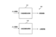
- FIG. 1 is a diagram showing an image processing apparatus 100 according to the first embodiment of the present invention.
- the image processing apparatus 100 includes a right eye image acquisition unit 101 that acquires a right eye image to be displayed on the right eye (first viewpoint) from the input image, and a left eye that is displayed on the left eye (second viewpoint) from the input image. And a left-eye image acquisition unit 102 that acquires an image.
- the right eye image acquisition unit 101, or the right eye image acquisition unit 101 and the left eye image acquisition unit 102 performs enhancement processing on a predetermined band of the input image.
- the difference (enhancement difference) is more than the detection limit.
- the input image may be a still image or a moving image.
- the emphasis process is performed on one of the left and right images with an emphasis amount different from that of the other emphasis process, thereby causing a visual field conflict, improving the contrast, and improving the image quality.
- the band enhancement processing may be performed only by the right eye image acquisition unit 101, or the band enhancement processing is performed by both the right eye image acquisition unit 101 and the left eye image processing unit 102, and the enhancement amount in the band enhancement processing is performed. May be different.
- the difference between the enhancement amounts of the right eye image and the left eye image is 0.1 or more and the enhancement amount is ⁇ 0.1 to 10 respectively.
- the enhancement amount of the band enhancement process may be changed according to time. Further, as will be described later, monochrome inversion processing or color inversion processing may be performed on either the right eye image processing unit or the left eye image processing unit instead of the band enhancement processing.
- band enhancement processing black-and-white reversal, or color reversal processing may be performed only on the attention area specified in the input image.
- the attention area By designating the attention area, it is possible to limit the area causing the visual field conflict, so that the viewer's attention can be collected in the specific area.
- a horizontal parallax may be added to one input image. Thereby, a parallax image (stereoscopic image) with improved image quality can be obtained.
- luminance correction for emphasizing contrast may be performed to obtain a right eye image and a left eye image. Thereby, the image quality can be further improved.
- the present embodiment is an example in which a band emphasis process is performed as a correction process for causing a binocular rivalry.
- a band emphasis process is performed as a correction process for causing a binocular rivalry.
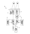
- FIG. 2 is a block diagram showing an image processing apparatus according to the second embodiment of the present invention.
- the image processing apparatus 110 includes a multi-view image display unit 1, a right-eye image luminance correction unit 2, a left-eye image luminance correction unit 3, and a right-eye band.
- the enhancement unit 4, the left eye band enhancement unit 5, the attention area designation unit 8, and the parallax generation unit 9 are included.
- the multi-eye image display unit 1 includes a right eye image display unit 6 and a left eye image display unit 7.
- the input image signal is input to the right eye band enhancement unit 4 and the left eye band enhancement unit 5, respectively.
- the same input signal is distributed.
- image data obtained by duplicating the same input image in advance may be used as the input to the right eye band emphasizing unit 4 and the left eye band emphasizing unit 5. Good.
- the right eye band emphasizing unit 4 emphasizes or suppresses a spatial frequency band sensitive to visual sharpness with respect to the input image, and generates a right eye band emphasized image.
- the left eye band emphasizing unit 5 has the same configuration as the right eye band emphasizing unit 4, but the amount of emphasis is different. Specifically, enhancement processing is performed using a value of the enhancement amount k different from that of the right-eye band enhancement unit 4, and a left-eye band enhancement image having a different enhancement amount from the right-eye band enhancement image is generated. This improves the contrast and improves the image quality.
- Y (x, y) represents the luminance value at the coordinate (x, y) point in one frame of the original image.
- K in the formula (1) is an enhancement amount, and sharpness increases as it increases from 0, and sharpness decreases as it decreases from 0.
- the BPF is a band-pass filter that filters band components sensitive to visual sharpness.
- the optimum amount of enhancement k for increasing the sharpness is determined depending on the shape of the BPF and the picture pattern. However, when the sharpness is increased in a normal use situation, it is desirable that there is a difference of 0.1 or more as the value of the enhancement amount k experimentally in order to perceive the difference in sharpness. When the difference in enhancement amount k (enhancement difference) is smaller than 0.1, it becomes difficult to distinguish the difference in sharpness. The limit point where the difference in sharpness can be discriminated by perception is called the detection limit. Sharpness increases as k increases, but when a certain level is exceeded, black and white bordering occurs near the edge due to excessive enhancement, resulting in a picture-like image rather than a real image.
- FIG. 3 is an explanatory diagram showing the relationship between the enhancement amount k and the sharpness.
- the sharpness characteristic curve 201 indicates that the sharpness increases in proportion to the enhancement amount up to a certain amount, but if the enhancement is excessive, the sharpness can no longer be sensed and decreases.
- the enhancement amount k In order to reduce sharpness, it is necessary to make the enhancement amount k smaller than zero. At this time, a so-called blurred image is output. In order to make humans perceive a reduction in sharpness experimentally, it is desirable that the enhancement amount be ⁇ 0.1 or less.
- the lower limit of k when reducing sharpness is -1.0, that is, when all band components are subtracted. If k is set to a value smaller than ⁇ 1.0, an unpredictable image effect will occur. That is, when one enhancement amount is set to 0 and the other sharpness is reduced, the enhancement amount is preferably ⁇ 1.0 ⁇ k ⁇ ⁇ 0.1.
- the emphasis amount between them is ⁇ 0.1 to 10
- the difference in emphasis amount (enhancement difference) is 0. It is preferably 1 to 10.
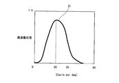
- FIG. 4 shows a band-pass filter characteristic 31 as an example of a band-pass characteristic of a BPF (band-pass filter).
- the band-pass filter characteristic 31 indicates a smooth linear filter having a peak in the vicinity of 20 cycle per deg [cpd].
- a method that emphasizes the sharpness of an image using a filter with similar characteristics is Sakata, "Pixel arrangement and image quality (line picture elements) (visual and image quality)", Television Society Technical Report, Vol.6, No. 37, 19831 (Non-Patent Document 2) and A. Inoue and J.Tajima, "Adaptive Image Sharpening Method Using Edge Sharpness," Vol.E76-D, No.10, pp.1174-1180, 1993 (non-patent Reference 3).
- a spatial filter having a continuous and smooth frequency characteristic having a peak in the vicinity of 10 to 50 cpd can be used.
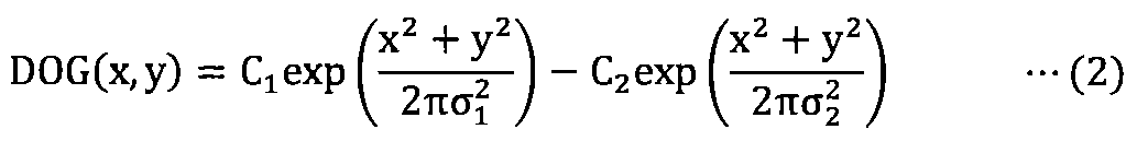
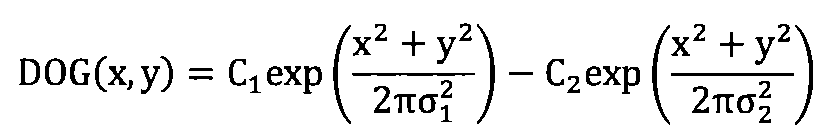
- the BPF there is a DOG (Difference-Of-Gaussian) filter of the following formula (2).
- C1 and C2 are constants.
- This filter is expressed by the difference of the Gaussian filter, and the parameters are ⁇ 1 and ⁇ 2 .
- ⁇ 1 is a value for controlling the rising edge on the low frequency side, and increasing the value has an effect of enhancing a larger edge.
- ⁇ 2 is a value that controls the cutoff on the high frequency side, and is effective in suppressing noise during emphasis.
- ⁇ 1 and ⁇ 2 differ depending on the resolution and pattern of the image.
- digital image data such as SDTV (Standard Definition TeleVision), HDTV (High Definition TeleVision), and digital camera photographs that are generally used at present
- the range of ⁇ 1 is 0.5 to 5.0
- the range of ⁇ 2 is It is preferably 0.0 to 1.0.
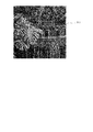
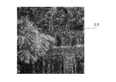
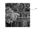
- FIG. 5 to FIG. 8 show examples of image processing using Expression (2).
- 5 shows an original image example 211
- FIG. 6 shows a sharpness reduction example 212
- FIG. 7 shows a sharpness-enhanced image example 213
- FIG. 8 shows an excessive sharpness-enhancement example 214.
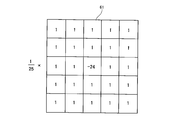
- a simple high-frequency filter 61 shown in FIG. 9 can be used as an example of a BPF with a reduced amount of calculation. This has the property of filtering high frequencies above the band sensitive to sharpness.
- the band enhancement processing described above is targeted for processing on the luminance signal Y.
- the color image signal RGB is input, it is common to perform the band emphasis processing only on the luminance Y signal after the luminance Y signal and the color difference UV signal are decomposed, because the amount of calculation is reduced.
- band enhancement processing may be performed independently for RGB.
- the parallax generation unit 9 adds horizontal parallax to only one image for stereoscopic viewing. Specifically, a process of translating each pixel in accordance with the depth of each pixel of the image is performed. For example, for an object in the distance, the movement amount is set to 0, and an image obtained by moving the region pixel of the nearby object X by d in the horizontal direction and a right eye band emphasized image are displayed on both eyes. By doing this, the object X can appear to be raised.
- the parallax generation unit 9 is disposed after the left eye band enhancement unit 5, but may be disposed after the right eye band enhancement unit 4. Further, when stereoscopic viewing is not performed, the amount of parallax movement may be set to zero. Note that when the parallax information is input to the input image signal, the parallax generation unit 9 is not essential.
- the right eye image luminance correction unit 2 extracts the luminance Y from the output image signal of the right eye band enhancement unit 4 and then emphasizes the contrast of light and dark to obtain a right eye display image.
- the contrast enhancement method there is a method in which the first tone curve 51 shown in FIG.
- the left eye image luminance correction unit 3 corrects the luminance of the output image signal of the left eye band enhancement unit 5 using parameters different from the right eye display image to obtain a left eye display image.
- the second tone curve 52 has a smaller inclination than the first tone curve 51 and a low contrast enhancement effect.
- the right eye image luminance correction unit 2 has the same operation as the right eye image luminance correction unit 202 in the conventional method
- the left eye image luminance correction unit 3 has the same operation as the right eye image luminance correction unit 203 in the conventional method.
- the luminance correction unit according to the present embodiment since there is band emphasis at the previous stage, a constant image quality improvement effect can be obtained without performing luminance correction in an extreme case.
- the multi-view image display unit 1 is a display device capable of presenting different images at different viewpoint positions, and a right-eye image display unit 6 that displays a right-eye display image and a left eye that displays a left-eye display image. And an image display unit 7.
- the multi-eye image display unit 1 can display the right eye image and the left eye image in correspondence with the left and right eyes. Therefore, it is often used as a stereoscopic display.
- the multi-view image display unit 1 there is a type in which different polarizing filters are attached to the right eye image projection unit and the left eye image projection unit, and an observer views binocular through polarized glasses.
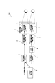
- the multi-view image display unit 1 is a multi-view display unit 45 using a lenticular lens as shown in FIG.
- the multi-view image display unit 45 is obtained by mounting lenticular lenses arranged side by side on the front surface of the liquid crystal panel 42. Images corresponding to the respective viewpoints are stored in the right eye image buffer 43 and the left eye image buffer 44.
- the right eye image and the left eye image are alternately synthesized in a strip shape and displayed in accordance with the size of the lenticular lens. Since the optical path is bent by the lenticular lens, it is possible to display images corresponding to the human left eye and right eye and images corresponding to a plurality of viewpoints.
- FIG. 11 shows an example of the multi-view image display unit, but the multi-view image display unit is not limited to these.
- an anaglyph method using color filters of different colors for the left and right eyes and an anaglyph method are developed to divide the wavelength range of visible light into six and use three different regions for the left and right eyes.
- liquid crystal shutter glasses stereo shutter glasses
- a parallax barrier (parallax barrier) is used to limit light reaching the left and right eyes, and each image corresponding to the left and right eyes is displayed on the display device in a time-sharing manner.
- a scan backlight method that switches the light input in the backlight of the display device in the right and left directions in a time-division manner and uses the lens together to control the image and light direction that enters the eye in a time-division manner.
- a viewer method in which a display device corresponding to each eye is arranged in a near-eye method in front of the eyes according to a head mounted display or the like, and an image corresponding to each eye is displayed on each display device. .
- This embodiment can be suitably applied to such various types of multi-view display units. Because, in the image processing method according to the present embodiment, the generated image is processed as necessary in accordance with various types of multi-view image display units and observed through the multi-view image display unit. This is because multi-view information can be recognized.
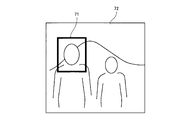
- the attention area designation section 8 designates a partial area that the viewer wants to pay attention to from the image.
- An example of the attention area is shown in FIG. FIG. 12 shows a person image 72, and an area surrounded by a rectangle is an attention area 71.
- the face area of the person in front is specified.
- the product area in the advertisement image can be considered as the attention area.
- an area specifying method there is a method of specifying using an input device such as a mouse. There is also a method of automatically detecting from each image frame using an image recognition technique.
- the attention area specifying unit 8 may be provided as necessary.
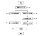
- FIG. 13 is a flowchart showing the operation of the image processing apparatus according to this embodiment.
- an image signal is input (step S1).
- a moving image is input, but even a still image can be processed in the same manner.
- the image signal is input to the right eye band enhancement unit 4 and the left eye band enhancement unit 5.
- the image signal input to the right eye band enhancement unit 4 is subjected to enhancement processing with a predetermined enhancement amount k1 (step S2) and input to the right eye image luminance correction unit 2.
- the image signal input to the left eye band enhancement unit 5 is subjected to enhancement processing with an enhancement amount k2 that is at least 0.1 different from the enhancement amount k1 (step S3). It is preferable that the enhancement amounts k1 and k2 are both ⁇ 0.1 to 10 and the absolute value of the difference (enhancement difference) between them is 0.1 to 10.
- the signal that has been band-enhanced in the left-eye band enhancement process 5 is input to the parallax generation unit 9 to be a predetermined parallax image (step S4). Thereafter, the image is input to the left eye image luminance correction unit 3.
- the right-eye image brightness correction unit 2 and the left-eye image brightness correction unit 3 optimize the brightness of the image (steps S5 and S6).
- the multi-eye image display unit 1 displays the right eye image and the left eye image (step S7).
- the present embodiment it is possible to improve the sharpness by increasing the high-frequency band component for the image of one viewpoint and intentionally causing a visual field conflict by the band emphasizing unit.
- the attention area it is possible to limit the area causing the visual field conflict, so that the viewer's attention can be collected in the specific area.
- FIG. 14 is a block diagram showing an image processing apparatus according to the third embodiment of the present invention.
- the image processing apparatus 120 includes a multi-view image display unit 11, a right eye band emphasizing unit 13, a left eye band emphasizing unit 14, and a right eye emphasis amount. It includes a series changing unit 15, a left eye enhancement amount time series changing unit 16, an attention area specifying unit 12, and a parallax generating unit 19.
- the multi-eye image display unit 11 includes a right eye image display unit 17 and a left eye image display unit 18.
- the input image signal is input to the right eye band enhancement unit 13 and the left eye band enhancement unit 14, respectively.
- the right eye band enhancement unit 13 and the left eye band enhancement unit 14 perform band enhancement processing on the input image frame.
- the right eye band enhancement unit 4 or the left eye band enhancement unit 5 can be used.
- the right eye band enhancement unit 13 performs band enhancement processing using the right eye enhancement amount calculated by the right eye enhancement amount time-series variation unit 15.
- the left eye band enhancement unit 14 performs band enhancement processing using the left eye enhancement amount calculated by the left eye enhancement amount time-series variation unit 16.
- the right eye enhancement amount time-series variation unit 15 outputs an enhancement amount that changes according to a predetermined rule.
- T1 (t) F ((t% N) +1)
- T2 (t) G ((t% N) +1) (3)
- % In formula (3) represents the remainder.
- predetermined N enhancement amounts are sequentially applied in time t.
- the enhancement amount in units of a plurality of frames.
- N 12
- F (n) ⁇ 1, 1, 1, 1, 3, 3, 3, 10, 10, 10, 10 ⁇
- the enhancement amount is 1 every 4 frames.
- 3 and 10 can be switched.
- T1 (t) F (1)
- T2 (t) F ((t% N) +1) (4)
- the parallax generation unit 19 is made to act on the output of the left eye band enhancement unit 14.
- the parallax generation unit 19 adds horizontal parallax to only one image for stereoscopic viewing, and operates in the same manner as the parallax generation unit 9. Note that when the parallax information is input to the input image signal, the parallax generation unit 19 is not essential.
- the output of the parallax generation unit 19 and the output of the right eye band enhancement unit 13 are input to the multiview image display unit 11.
- the multi-eye image display unit 11 is a display device capable of presenting different images at different viewpoint positions.
- the right-eye image display unit 17 that displays a right-eye display image and the left eye that displays a left-eye display image.
- the multi-view image display unit 11 operates in the same manner as the multi-view image display unit 1 in the right-eye embodiment.
- the attention area designation unit 12 is a block that designates a partial area that the viewer wants to pay attention to from the image, and is a block that performs the same movement as the attention area designation unit 8.
- the designated attention area is reflected in the two band emphasis sections, and the band emphasis section performs band emphasis processing only within the attention area.
- Non-Patent Document 4 when humans present different images alternately in the range of 2Hz to 50Hz, I feel a flicker. Usually, this flickering sensation causes discomfort, and measures are taken to suppress this frequency band peak. However, it is necessary to present a frame that changes with time in order to express how the object shines, such as sparkling water, metallic luster, metallic texture, and star blink.
- the same effect as in the first embodiment is achieved, and the glossiness of the object is obtained by temporally changing the image of one eye and intentionally causing a visual field conflict. Can be reproduced.
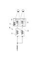
- FIG. 15 is a block diagram showing an image processing apparatus according to the fourth embodiment of the present invention.
- the image display device 130 according to the fourth exemplary embodiment includes a multi-view image display unit 21, a black and white reversing unit 22, an attention area designation unit 23, and a parallax generation unit 24.
- the multi-eye image display unit 21 includes a right eye image display unit 25 and a left eye image display unit 26.
- the black and white reversing unit 22 inverts only the luminance signal of the input image signal.
- the input image signal is decomposed into a luminance signal and a color signal.
- black and white inversion tone curve correction is performed only on the luminance signal.
- the black-and-white inversion tone curve 81 is a downward-sloping tone curve such that when the input luminance Y is 255 (white), the output luminance Y ′ is 0 (black).
- the original color signal can be used to convert to a color image signal in which only the luminance is inverted.
- Equation (5) 255 ⁇ Y (5)
- the parallax generation unit 24 adds horizontal parallax to only one image for stereoscopic viewing, and operates in the same manner as the parallax generation unit 9.
- the parallax generation unit is operated on an image different from the image that is reversed in black and white.
- the parallax generation unit may be operated on an image that is reversed in black and white. Note that when the parallax information is input to the input image signal, the parallax generation unit 24 is not essential.
- Output image signals from the black and white reversing unit 22 and the parallax generating unit 24 are input to the multi-view image display unit 21.
- the multi-eye image display unit 21 is a display device capable of presenting different images at different viewpoint positions.
- the right-eye image display unit 25 displays a right-eye display image and the left eye displays a left-eye display image.
- the multi-view image display unit 21 operates in the same manner as the multi-view image display unit 1 in the first embodiment.
- the attention area designation section 23 is a block for designating a partial area that the viewer wants to pay attention to from the image, and moves in the same manner as the attention area designation section 8.
- the designated attention area is reflected in the black and white reversing unit 22, and the black and white reversing unit 22 performs black and white reversal only within the attention area.
- the fifth embodiment of the present invention includes a multi-view image display unit 21, a color inversion unit 27, an attention area designation unit 23, and a parallax generation unit 24.
- the multi-eye image display unit 21 includes a right eye image display unit 25 and a left eye image display unit 26.
- the color reversing unit 27 is a means for reversing the input image signal including color information.
- the color reversing unit 27 there is a method of reversing R, G, B independently with respect to the input image signal RGB.
- the inversion method there is a method of applying Equation (6) to the RGB signal.
- the RGB signal is an 8-bit signal in the range of 0 to 255.
- the color can be inverted by subtracting the current signal independently from the maximum value as shown in equation (6).
- B ' 255-B
- the color reversing unit 27 there is a method of reversing after converting the luminance color difference signal.
- the input signal RGB is decomposed into YUV which is a luminance color difference signal.
- YCbCr standardized by ITU-R BT.601 can be used as the YUV signal.
- Y represents a luminance signal
- Cb and Cr represent a color difference.
- the color inversion method there is a method in which Y, Cb, and Cr are independently inverted as shown in Expression (7).
- Cr ' 255-Cr
- tone curve correction such as the black and white inversion tone curve 81 of FIG. 16 can be applied as signal inversion processing.
- the parallax generation unit 24 adds horizontal parallax to only one image for stereoscopic viewing, and operates in the same manner as the parallax generation unit 9.
- the parallax generation unit is operated on an image different from the image whose color is inverted, but the parallax generation unit may be operated on an image whose color is inverted. Note that when the parallax information is input to the input image signal, the parallax generation unit 9 is not essential.
- the output image signals of the color reversing unit 27 and the parallax generating unit 24 are input to the multi-view image display unit 21.
- the multi-eye image display unit 21 is a display device capable of presenting different images at different viewpoint positions.
- the right-eye image display unit 25 displays a right-eye display image and the left eye displays a left-eye display image.
- the multi-view image display unit 21 operates in the same manner as the multi-view image display unit 1 in the right-eye embodiment.
- the attention area designation section 23 is a block that designates a partial area that the viewer wants to pay attention to from the image, and is a block that moves in the same manner as the attention area designation section 8.
- the designated attention area is reflected in the color inversion unit 27, and color inversion is performed only within the attention area.
- the hardware configuration has been described.
- the present invention is not limited to this, and arbitrary processing may be realized by causing a CPU (Central Processing Unit) to execute a computer program.
- the computer program can be provided by being recorded on a recording medium, or can be provided by being transmitted via the Internet or another transmission medium.
- the present invention can be used for an image processing method, an image processing apparatus, and a program for improving display quality in a system that displays different images at a plurality of viewpoints.
Abstract
Description
2 右眼画像輝度補正部
3 左眼画像輝度補正部
4、13 右眼帯域強調部
5、14 左眼帯域強調部
6、17、25 右眼画像表示部
7、18、26 左眼画像表示部
8、12、23 注目領域指定部
9、19、24、29 視差生成部
15 右眼強調量時系列変動部
16 左眼強調量時系列変動部
22 白黒反転部
27 色反転部
31 帯域濾過フィルタ特性
42 液晶パネル
43、44 画像バッファ
45 多眼表示部
51、52 トーンカーブ
61 高周波フィルタ
71 注目領域
72 人物画像
81 白黒反転トーンカーブ
100、110、120、130 画像処理装置
101 右眼補正処理部
102 左眼補正処理部
次に、発明の第2の実施の形態について説明する。本実施の形態は、視野闘争を生じさせるための補正処理として帯域強調処理を施す例である。ここでは先ず、本実施の形態にかかる画像処理装置において、質感が変化して画質が向上する原理について説明する。大山、今井、和気編、"感覚・知覚心理学ハンドブック"、誠信書房、pp.744-751(非特許文献1)によると、左右の目に異なる画像を提示すると、脳内ではこれらの画像が合成されて知覚される。その知覚状態は安定ではなく、どちらかの画像が支配的に見えたり、両眼の画像が交互に見えたりする。この現象は視覚心理学において視野闘争とよばれる。

次に、本発明の第3の実施の形態について図面を参照して詳細に説明する。本実施の形態は、第1の実施の形態の帯域強調処理において、強調量を時系列に変動させる例である。図14は、本発明の第3の実施の形態にかかる画像処理装置を示すブロック図である。図14に示すように、第3の実施の形態にかかる画像処理装置120は、多眼画像表示部11と、右眼帯域強調部13と、左眼帯域強調部14と、右眼強調量時系列変動部15と、左眼強調量時系列変動部16と、注目領域指定部12と、視差生成部19とを有する。多眼画像表示部11は、右眼画像表示部17と、左眼画像表示部18とを有する。
T1(t)=F((t%N)+1)
T2(t)=G((t%N)+1) ・・・(3)
T1(t)=F(1)
T2(t)=F((t%N)+1) ・・・(4)
次に、本発明の第4の実施の形態について図面を参照して詳細に説明する。本実施の形態は、視野闘争を生じさせるための補正処理として白黒反転処理を施す例である。図15は、本発明の第4の実施の形態にかかる画像処理装置を示すブロック図である。図15に示すように、第4の実施の形態にかかる画像表示装置130は、多眼画像表示部21と、白黒反転部22と、注目領域指定部23と、視差生成部24とから構成されている。多眼画像表示部21は、右眼画像表示部25と、左眼画像表示部26とを有する。白黒反転部22は、入力画像信号の輝度信号のみを反転する。
Y'=255-Y ・・・(5)
次に、本発明の第5の実施の形態について図面を参照して詳細に説明する。図17を参照すると、本発明の第5の実施の形態は、多眼画像表示部21と、色反転部27と、注目領域指定部23と、視差生成部24とから構成されている。多眼画像表示部21は、右眼画像表示部25と、左眼画像表示部26とを含む。
R'=255-R
G'=255-G ・・・(6)
B'=255-B
Y'=255-Y
Cb'=255-Cb ・・・(7)
Cr'=255-Cr
Claims (22)
- 入力画像から右眼に表示する右眼画像及び左眼に表示する左眼画像の所定の帯域を強調処理又は反強調処理する画像強調工程を有し、
前記画像強調工程では、前記右眼画像と前記左眼画像の強調量の差を、知覚によって鮮鋭さの違いを判別できる限界点である検知限以上とする、画像処理方法。 - 前記右眼画像と前記左眼画像の強調量の差が0.1以上である
ことを特徴とする請求項1記載の画像処理方法。 - 前記右眼画像と前記左眼画像の強調量の差が10以下である
ことを特徴とする請求項2記載の画像処理方法。 - 視野闘争を発生するよう前記右眼画像と前記左眼画像の強調量を異ならせる
ことを特徴とする請求項3記載の画像処理方法。 - 前記帯域強調処理の強調量を時間に応じて変動させる
ことを特徴とする請求項1乃至4のいずれか1項記載の画像処理方法。 - 前記画像強調工程では、C1、C2を定数、σ1を0.5乃至5.0の範囲のパラメータ、σ2を0.0乃至1.0の範囲のパラメータとしたとき、下記で表わされるフィルタを使用する
ことを特徴とする請求項1乃至5のいずれか1項記載の画像処理方法。
- 右眼に表示する右眼画像を入力画像とし、左眼に表示する左眼画像を前記入力画像を白黒反転又は色反転することによって生成する画像処理方法。
- 入力画像において指定された注目領域に対してのみ帯域強調処理又は白黒反転を施す
ことを特徴とする請求項1乃至7のいずれか1項記載の画像処理方法。 - 一方の前記入力画像に対し水平方向の視差を付加する
ことを特徴とする請求項1乃至8のいずれか1項記載の画像処理方法。 - 前記入力画像の帯域強調処理をした後、コントラストを強調する輝度補正を行って前記右眼画像及び左眼画像とする
ことを特徴とする請求項1乃至6のいずれか1項記載の画像処理方法。 - 入力画像から右眼に表示する右眼画像を取得する右眼画像取得手段と、
前記入力画像から左眼に表示する左眼画像を取得する左眼画像取得手段とを有し、
前記右眼画像取得手段及び/又は左眼画像取得手段は、前記入力画像に対して所定の帯域を強調処理又は反強調処理するものであって、前記右眼画像と前記左眼画像の強調量の差を、知覚によって鮮鋭さの違いを判別できる限界点である検知限以上とする、画像処理装置。 - 前記右眼画像と前記左眼画像の強調量の差が0.1以上である
ことを特徴とする請求項11記載の画像処理装置。 - 前記右眼画像と前記左眼画像の強調量の差が10以下である
ことを特徴とする請求項12記載の画像処理装置。 - 前記右眼画像取得手段及び左眼画像取得手段は、視野闘争を発生するようそれぞれ前記右眼画像及び前記左眼画像の強調量を異ならせる
ことを特徴とする請求項13記載の画像処理装置。 - 前記右眼画像取得手段及び/又は左眼画像取得手段は、前記帯域強調処理の強調量を時間に応じて変動させる
ことを特徴とする請求項11乃至14のいずれか1項記載の画像処理装置。 - 前記右眼画像取得手段及び左眼画像取得手段は、C1、C2を定数、σ1を0.5乃至5.0の範囲のパラメータ、σ2を0.0乃至1.0の範囲のパラメータとしたとき、下記で表わされるフィルタを使用する
ことを特徴とする請求項11乃至15のいずれか1項記載の画像処理装置。

- 入力画像から右眼に表示する右眼画像を取得する右眼画像取得手段と、
前記入力画像から左眼に表示する左眼画像を取得する左眼画像取得手段とを有し、
前記右眼画像取得手段は、取得した前記入力画像を白黒反転又は色反転する、画像処理装置。 - 入力画像において注目領域を指定する注目領域指定手段を更に有し、
注目領域指定手段は、前記注目領域に対してのみ帯域強調処理又は白黒反転を施す
ことを特徴とする請求項11乃至17のいずれか1項記載の画像処理装置。 - 一方の前記入力画像に対し水平方向の視差を付加する視差生成手段を更に有する
ことを特徴とする請求項11乃至18のいずれか1項記載の画像処理装置。 - 前記右眼画像取得手段及び左眼画像取得手段は、前記入力画像の帯域強調処理をした後、コントラストを強調する輝度補正を行って前記右眼画像及び左眼画像とする
ことを特徴とする請求項11乃至16のいずれか1項記載の画像処理装置。 - 所定の動作をコンピュータに実行させるためのプログラムを格納した記録媒体であって、
入力画像から右眼に表示する右眼画像及び左眼に表示する左眼画像の所定の帯域を強調処理又は反強調処理する画像強調工程を有し、
前記画像強調工程では、前記右眼画像と前記左眼画像の強調量の差を、知覚によって鮮鋭さの違いを判別できる限界点である検知限以上とする、プログラムを格納した記録媒体。 - 所定の動作をコンピュータに実行させるためのプログラムを格納した記録媒体であって、
右眼に表示する右眼画像を入力画像とし、左眼に表示する左眼画像を前記入力画像を白黒反転又は色反転することによって生成するプログラムを格納した記録媒体。
Priority Applications (3)
| Application Number | Priority Date | Filing Date | Title |
|---|---|---|---|
| US12/921,050 US8670607B2 (en) | 2008-04-03 | 2009-03-27 | Image processing method, image processing device and recording medium |
| EP09728149.7A EP2259601B1 (en) | 2008-04-03 | 2009-03-27 | Image processing method, image processing device, and recording medium |
| JP2010505853A JP5500066B2 (ja) | 2008-04-03 | 2009-03-27 | 画像処理方法、画像処理装置及びプログラム |
Applications Claiming Priority (2)
| Application Number | Priority Date | Filing Date | Title |
|---|---|---|---|
| JP2008-096774 | 2008-04-03 | ||
| JP2008096774 | 2008-04-03 |
Publications (1)
| Publication Number | Publication Date |
|---|---|
| WO2009123066A1 true WO2009123066A1 (ja) | 2009-10-08 |
Family
ID=41135444
Family Applications (1)
| Application Number | Title | Priority Date | Filing Date |
|---|---|---|---|
| PCT/JP2009/056335 WO2009123066A1 (ja) | 2008-04-03 | 2009-03-27 | 画像処理方法、画像処理装置及び記録媒体 |
Country Status (4)
| Country | Link |
|---|---|
| US (1) | US8670607B2 (ja) |
| EP (1) | EP2259601B1 (ja) |
| JP (1) | JP5500066B2 (ja) |
| WO (1) | WO2009123066A1 (ja) |
Cited By (10)
| Publication number | Priority date | Publication date | Assignee | Title |
|---|---|---|---|---|
| JP2010213054A (ja) * | 2009-03-11 | 2010-09-24 | Toppan Printing Co Ltd | 画像生成方法 |
| JP2012053359A (ja) * | 2010-09-02 | 2012-03-15 | Canon Inc | 画像処理装置およびその方法 |
| CN102420997A (zh) * | 2010-09-28 | 2012-04-18 | 承景科技股份有限公司 | 图像处理方法 |
| WO2012056695A1 (ja) * | 2010-10-28 | 2012-05-03 | 富士フイルム株式会社 | 立体視画像表示装置および方法並びにプログラム |
| WO2012108187A1 (ja) * | 2011-02-08 | 2012-08-16 | 富士フイルム株式会社 | 立体視用画像生成装置および方法、並びにプログラム |
| JP2012160922A (ja) * | 2011-01-31 | 2012-08-23 | Toshiba Corp | 映像信号処理装置及び映像信号処理方法 |
| CN103392342A (zh) * | 2011-12-21 | 2013-11-13 | 青岛海信电器股份有限公司 | 视区调整的方法和装置、能实现立体显示视频信号的设备 |
| WO2014080947A1 (ja) * | 2012-11-20 | 2014-05-30 | 株式会社 東芝 | X線診断装置、医用画像処理装置、画像処理装置、x線診断装置制御プログラム、医用画像処理プログラム、及び画像処理プログラム |
| JPWO2018220694A1 (ja) * | 2017-05-30 | 2020-04-02 | ソフトバンク株式会社 | 映像処理装置、映像処理方法、およびプログラム |
| JP2020155827A (ja) * | 2019-03-18 | 2020-09-24 | 本田技研工業株式会社 | 視認装置および視認方法 |
Families Citing this family (19)
| Publication number | Priority date | Publication date | Assignee | Title |
|---|---|---|---|---|
| EP2259600B1 (en) * | 2008-04-03 | 2014-08-20 | NLT Technologies, Ltd. | Image processing method, image processing device, and recording medium |
| US9524700B2 (en) * | 2009-05-14 | 2016-12-20 | Pure Depth Limited | Method and system for displaying images of various formats on a single display |
| US8878913B2 (en) * | 2010-03-12 | 2014-11-04 | Sony Corporation | Extended command stream for closed caption disparity |
| TWI482484B (zh) * | 2011-06-17 | 2015-04-21 | Wistron Corp | 立體顯示系統及其方法 |
| WO2013001165A1 (en) * | 2011-06-28 | 2013-01-03 | Nokia Corporation | A method, a system, a viewing device and a computer program for picture rendering |
| US20130044939A1 (en) * | 2011-08-18 | 2013-02-21 | Ucl Business Plc | Method and system for modifying binocular images |
| EP2600616A3 (en) * | 2011-11-30 | 2014-04-30 | Thomson Licensing | Antighosting method using binocular suppression. |
| US20140253698A1 (en) * | 2013-03-11 | 2014-09-11 | Allan Thomas Evans | System, apparatus, and method for enhancing stereoscopic images |
| US10303242B2 (en) | 2014-01-06 | 2019-05-28 | Avegant Corp. | Media chair apparatus, system, and method |
| US10409079B2 (en) | 2014-01-06 | 2019-09-10 | Avegant Corp. | Apparatus, system, and method for displaying an image using a plate |
| CN105100769B (zh) * | 2014-05-05 | 2018-08-28 | 浙江大学 | 一种视觉特效图像或视频对的生成方法及装置 |
| JP2017520968A (ja) * | 2014-05-12 | 2017-07-27 | コーニンクレッカ フィリップス エヌ ヴェKoninklijke Philips N.V. | ディスプレイのための駆動値の生成 |
| FR3026852B1 (fr) * | 2014-10-03 | 2016-12-02 | Thales Sa | Systeme de visualisation a ecran semi-transparent partage par deux observateurs |
| WO2016108831A1 (en) * | 2014-12-30 | 2016-07-07 | Halliburton Energy Services, Inc. | Galvanic measurement apparatus, systems, and methods |
| US10341637B1 (en) * | 2015-03-11 | 2019-07-02 | Facebook Technologies, Llc | Full frame uniformity across panels |
| US9823474B2 (en) | 2015-04-02 | 2017-11-21 | Avegant Corp. | System, apparatus, and method for displaying an image with a wider field of view |
| US9995857B2 (en) | 2015-04-03 | 2018-06-12 | Avegant Corp. | System, apparatus, and method for displaying an image using focal modulation |
| JP2016212177A (ja) * | 2015-05-01 | 2016-12-15 | セイコーエプソン株式会社 | 透過型表示装置 |
| US10762708B2 (en) | 2016-06-23 | 2020-09-01 | Intel Corporation | Presentation of scenes for binocular rivalry perception |
Citations (4)
| Publication number | Priority date | Publication date | Assignee | Title |
|---|---|---|---|---|
| JPH0759113A (ja) * | 1993-08-20 | 1995-03-03 | Seiko Epson Corp | 疑似立体映像表示装置及び疑似立体映像の生成方法 |
| JPH10224822A (ja) | 1997-01-31 | 1998-08-21 | Sony Corp | 映像表示方法および表示装置 |
| JPH11511316A (ja) | 1996-06-07 | 1999-09-28 | フィリップス エレクトロニクス ネムローゼ フェンノートシャップ | 立体画像ディスプレイ駆動装置 |
| JP2004229881A (ja) | 2003-01-30 | 2004-08-19 | Sophia Co Ltd | 画像表示装置及び画像表示装置を備える遊技機 |
Family Cites Families (30)
| Publication number | Priority date | Publication date | Assignee | Title |
|---|---|---|---|---|
| JP3306173B2 (ja) * | 1993-07-06 | 2002-07-24 | オリンパス光学工業株式会社 | 映像表示装置 |
| JPH07159723A (ja) * | 1993-12-03 | 1995-06-23 | Terumo Corp | 立体画像表示装置 |
| US6384859B1 (en) * | 1995-03-29 | 2002-05-07 | Sanyo Electric Co., Ltd. | Methods for creating an image for a three-dimensional display, for calculating depth information and for image processing using the depth information |
| ID27878A (id) * | 1997-12-05 | 2001-05-03 | Dynamic Digital Depth Res Pty | Konversi image yang ditingkatkan dan teknik mengenkodekan |
| JP2001186442A (ja) * | 1999-12-27 | 2001-07-06 | Minolta Co Ltd | 映像表示装置 |
| US20010042086A1 (en) * | 2000-01-28 | 2001-11-15 | Konica Corporation | Print order receiving device, print receiving producing system and print order data product |
| JP2001299733A (ja) * | 2000-04-27 | 2001-10-30 | Konica Corp | Pci放射線画像処理装置、pci放射線画像検出処理装置、pci放射線画像出力装置及びpci画像診断支援装置 |
| US7401923B2 (en) * | 2004-03-09 | 2008-07-22 | Fergason Patent Properties, Llc | Monitor for showing high-resolution and three-dimensional images and method |
| AUPQ887100A0 (en) * | 2000-07-19 | 2000-08-10 | Dynamic Digital Depth Research Pty Ltd | Image processing and encoding techniques |
| US7508485B2 (en) * | 2001-01-23 | 2009-03-24 | Kenneth Martin Jacobs | System and method for controlling 3D viewing spectacles |
| JP4940507B2 (ja) * | 2001-04-19 | 2012-05-30 | 凸版印刷株式会社 | 立体像表示体およびその観察方法 |
| JP3941561B2 (ja) * | 2001-09-14 | 2007-07-04 | 三菱電機株式会社 | 両面表示型液晶表示装置および情報機器 |
| US7033025B2 (en) | 2002-05-17 | 2006-04-25 | Virtocc, Inc. | Interactive occlusion system |
| KR100477659B1 (ko) * | 2002-08-10 | 2005-03-22 | 삼성전자주식회사 | 주파수 특성을 검출하는 장치 및 방법 |
| AU2003286453A1 (en) * | 2002-10-15 | 2004-05-04 | David J. Mcintyre | System and method for simulating visual defects |
| JP2005049811A (ja) * | 2003-07-15 | 2005-02-24 | Olympus Corp | 立体表示装置及び立体視観察装置 |
| TWI231206B (en) * | 2004-02-18 | 2005-04-21 | Chi-Wen Hsieh | Apparatus and system for monitoring the activity of an eye portion |
| JP4537104B2 (ja) * | 2004-03-31 | 2010-09-01 | キヤノン株式会社 | マーカ検出方法、マーカ検出装置、位置姿勢推定方法、及び複合現実空間提示方法 |
| KR100648308B1 (ko) * | 2004-08-12 | 2006-11-23 | 삼성전자주식회사 | 해상도 변환방법 및 장치 |
| US8462384B2 (en) * | 2004-09-29 | 2013-06-11 | Apple Inc. | Methods and apparatuses for aesthetically enhanced image conversion |
| JP4196212B2 (ja) * | 2004-12-24 | 2008-12-17 | セイコーエプソン株式会社 | 画像処理装置、画像処理方法および画像処理プログラム |
| JP4738870B2 (ja) * | 2005-04-08 | 2011-08-03 | キヤノン株式会社 | 情報処理方法、情報処理装置および遠隔複合現実感共有装置 |
| EP2501139A3 (en) * | 2005-05-26 | 2014-01-08 | RealD Inc. | Ghost-compensation for improved stereoscopic projection |
| US20070165942A1 (en) * | 2006-01-18 | 2007-07-19 | Eastman Kodak Company | Method for rectifying stereoscopic display systems |
| US20080002255A1 (en) * | 2006-07-02 | 2008-01-03 | Amon Tavor | Stereoscopic Display Using a Color Parallax Barrier |
| US20080095464A1 (en) * | 2006-10-20 | 2008-04-24 | Quvis, Inc. | System and Method for Representing Motion Imagery Data |
| KR101213205B1 (ko) * | 2006-11-23 | 2012-12-17 | 삼성전자주식회사 | 컬러 재현 시스템 및 방법 |
| US20080151193A1 (en) * | 2006-12-26 | 2008-06-26 | Texas Instruments Incorporated | Stereoscopic imaging systems utilizing solid-state illumination and passive glasses |
| US8208009B2 (en) * | 2008-02-05 | 2012-06-26 | Disney Enterprises, Inc. | Stereoscopic image generation using retinal rivalry in scene transitions |
| EP2259600B1 (en) * | 2008-04-03 | 2014-08-20 | NLT Technologies, Ltd. | Image processing method, image processing device, and recording medium |
-
2009
- 2009-03-27 JP JP2010505853A patent/JP5500066B2/ja active Active
- 2009-03-27 EP EP09728149.7A patent/EP2259601B1/en active Active
- 2009-03-27 WO PCT/JP2009/056335 patent/WO2009123066A1/ja active Application Filing
- 2009-03-27 US US12/921,050 patent/US8670607B2/en active Active
Patent Citations (4)
| Publication number | Priority date | Publication date | Assignee | Title |
|---|---|---|---|---|
| JPH0759113A (ja) * | 1993-08-20 | 1995-03-03 | Seiko Epson Corp | 疑似立体映像表示装置及び疑似立体映像の生成方法 |
| JPH11511316A (ja) | 1996-06-07 | 1999-09-28 | フィリップス エレクトロニクス ネムローゼ フェンノートシャップ | 立体画像ディスプレイ駆動装置 |
| JPH10224822A (ja) | 1997-01-31 | 1998-08-21 | Sony Corp | 映像表示方法および表示装置 |
| JP2004229881A (ja) | 2003-01-30 | 2004-08-19 | Sophia Co Ltd | 画像表示装置及び画像表示装置を備える遊技機 |
Non-Patent Citations (5)
| Title |
|---|
| A. INOUE; J. TAJIMA, ADAPTIVE IMAGE SHARPENING METHOD USING EDGE SHARPNESS, vol. E76-D, no. 10, 1993, pages 1174 - 1180 |
| OOYAMA, IMAI, AND WAKI: "Sensory and Perceptual Psychology handbook", SEISHIN SHOBO, pages: 552 - 555 |
| OOYAMA, IMAI, WAKI: ""Sensory/Perception handbook",", SEISHIN SHOBO,, pages: 744 - 754 |
| SAKATA: "Effect of picture element on picture quality (stripe element) (vision and image quality)", THE INSTITUTE OF TELEVISION ENGINEERS OF JAPAN TECHNICAL REPORT, vol. 6, no. 37, pages 19831 |
| See also references of EP2259601A4 |
Cited By (12)
| Publication number | Priority date | Publication date | Assignee | Title |
|---|---|---|---|---|
| JP2010213054A (ja) * | 2009-03-11 | 2010-09-24 | Toppan Printing Co Ltd | 画像生成方法 |
| JP2012053359A (ja) * | 2010-09-02 | 2012-03-15 | Canon Inc | 画像処理装置およびその方法 |
| CN102420997A (zh) * | 2010-09-28 | 2012-04-18 | 承景科技股份有限公司 | 图像处理方法 |
| WO2012056695A1 (ja) * | 2010-10-28 | 2012-05-03 | 富士フイルム株式会社 | 立体視画像表示装置および方法並びにプログラム |
| JP2012160922A (ja) * | 2011-01-31 | 2012-08-23 | Toshiba Corp | 映像信号処理装置及び映像信号処理方法 |
| WO2012108187A1 (ja) * | 2011-02-08 | 2012-08-16 | 富士フイルム株式会社 | 立体視用画像生成装置および方法、並びにプログラム |
| CN103348684A (zh) * | 2011-02-08 | 2013-10-09 | 富士胶片株式会社 | 立体图像生成设备、立体图像生成方法以及立体图像生成程序 |
| CN103392342A (zh) * | 2011-12-21 | 2013-11-13 | 青岛海信电器股份有限公司 | 视区调整的方法和装置、能实现立体显示视频信号的设备 |
| WO2014080947A1 (ja) * | 2012-11-20 | 2014-05-30 | 株式会社 東芝 | X線診断装置、医用画像処理装置、画像処理装置、x線診断装置制御プログラム、医用画像処理プログラム、及び画像処理プログラム |
| JP2014121589A (ja) * | 2012-11-20 | 2014-07-03 | Toshiba Corp | X線診断装置、医用画像処理装置、画像処理装置、x線診断装置制御プログラム、医用画像処理プログラム、及び画像処理プログラム |
| JPWO2018220694A1 (ja) * | 2017-05-30 | 2020-04-02 | ソフトバンク株式会社 | 映像処理装置、映像処理方法、およびプログラム |
| JP2020155827A (ja) * | 2019-03-18 | 2020-09-24 | 本田技研工業株式会社 | 視認装置および視認方法 |
Also Published As
| Publication number | Publication date |
|---|---|
| JP5500066B2 (ja) | 2014-05-21 |
| US8670607B2 (en) | 2014-03-11 |
| JPWO2009123066A1 (ja) | 2011-07-28 |
| US20110002533A1 (en) | 2011-01-06 |
| EP2259601A1 (en) | 2010-12-08 |
| EP2259601B1 (en) | 2016-09-07 |
| EP2259601A4 (en) | 2013-07-24 |
Similar Documents
| Publication | Publication Date | Title |
|---|---|---|
| JP5500066B2 (ja) | 画像処理方法、画像処理装置及びプログラム | |
| JP5522404B2 (ja) | 画像処理方法、画像処理装置及びプログラム | |
| JP5347717B2 (ja) | 画像処理装置、および画像処理方法、並びにプログラム | |
| US8660337B2 (en) | Image processing apparatus, method and computer program to adjust 3D information based on human visual characteristics | |
| US8587638B2 (en) | Supporting a 3D presentation | |
| JP5615136B2 (ja) | 立体画像補正方法、立体表示装置、および立体画像生成装置 | |
| JP4098235B2 (ja) | ステレオスコピック画像処理機器および方法 | |
| JP2011124935A (ja) | 画像処理装置、および画像処理方法、並びにプログラム | |
| JP5673032B2 (ja) | 画像処理装置、表示装置、画像処理方法及びプログラム | |
| JP2011210027A (ja) | 画像処理装置および方法並びにプログラム | |
| US10547832B2 (en) | Image processing apparatus, method, and storage medium for executing gradation on stereoscopic images | |
| KR20130040771A (ko) | 입체 영상 처리 장치 및 방법 및 프로그램 | |
| US9088774B2 (en) | Image processing apparatus, image processing method and program | |
| JP2012120057A (ja) | 画像処理装置、および画像処理方法、並びにプログラム | |
| KR20120101881A (ko) | 영상 디스플레이 방법 및 장치 | |
| JP2018191191A (ja) | 立体映像生成装置 | |
| CN113661514A (zh) | 用于增强图像的设备和方法 | |
| EP2549760A2 (en) | Method for improving three-dimensional display quality | |
| JP5569635B2 (ja) | 画像処理装置、および画像処理方法、並びにプログラム | |
| JP2014011492A (ja) | 画像処理装置および画像処理方法 | |
| US20130076733A1 (en) | Image processing apparatus, image processing method, and image processing program | |
| JP2012137696A (ja) | 液晶表示装置 |
Legal Events
| Date | Code | Title | Description |
|---|---|---|---|
| 121 | Ep: the epo has been informed by wipo that ep was designated in this application |
Ref document number: 09728149 Country of ref document: EP Kind code of ref document: A1 |
|
| REEP | Request for entry into the european phase |
Ref document number: 2009728149 Country of ref document: EP |
|
| WWE | Wipo information: entry into national phase |
Ref document number: 2009728149 Country of ref document: EP |
|
| WWE | Wipo information: entry into national phase |
Ref document number: 12921050 Country of ref document: US |
|
| WWE | Wipo information: entry into national phase |
Ref document number: 2010505853 Country of ref document: JP |
|
| NENP | Non-entry into the national phase |
Ref country code: DE |