WO2009119263A1 - 車両速度制御装置 - Google Patents
車両速度制御装置 Download PDFInfo
- Publication number
- WO2009119263A1 WO2009119263A1 PCT/JP2009/054016 JP2009054016W WO2009119263A1 WO 2009119263 A1 WO2009119263 A1 WO 2009119263A1 JP 2009054016 W JP2009054016 W JP 2009054016W WO 2009119263 A1 WO2009119263 A1 WO 2009119263A1
- Authority
- WO
- WIPO (PCT)
- Prior art keywords
- vehicle
- vehicle speed
- unit
- driving force
- sensitivity
- Prior art date
- Legal status (The legal status is an assumption and is not a legal conclusion. Google has not performed a legal analysis and makes no representation as to the accuracy of the status listed.)
- Ceased
Links
Images



Classifications
-
- G—PHYSICS
- G01—MEASURING; TESTING
- G01M—TESTING STATIC OR DYNAMIC BALANCE OF MACHINES OR STRUCTURES; TESTING OF STRUCTURES OR APPARATUS, NOT OTHERWISE PROVIDED FOR
- G01M15/00—Testing of engines
- G01M15/02—Details or accessories of testing apparatus
-
- G—PHYSICS
- G01—MEASURING; TESTING
- G01M—TESTING STATIC OR DYNAMIC BALANCE OF MACHINES OR STRUCTURES; TESTING OF STRUCTURES OR APPARATUS, NOT OTHERWISE PROVIDED FOR
- G01M17/00—Testing of vehicles
-
- B—PERFORMING OPERATIONS; TRANSPORTING
- B60—VEHICLES IN GENERAL
- B60W—CONJOINT CONTROL OF VEHICLE SUB-UNITS OF DIFFERENT TYPE OR DIFFERENT FUNCTION; CONTROL SYSTEMS SPECIALLY ADAPTED FOR HYBRID VEHICLES; ROAD VEHICLE DRIVE CONTROL SYSTEMS FOR PURPOSES NOT RELATED TO THE CONTROL OF A PARTICULAR SUB-UNIT
- B60W2520/00—Input parameters relating to overall vehicle dynamics
- B60W2520/10—Longitudinal speed
Definitions
- the present invention relates to a vehicle speed control device used when testing an engine on an engine bench or a chassis dynamometer.
- FIG. 5 shows the configuration of the vehicle speed control device disclosed in Patent Document 1.
- reference numeral 1 denotes an acceleration force calculation unit, and the acceleration force on the command side is expressed by acceleration of vehicle speed command Vs ⁇ vehicle mass (vehicle weight M).
- the running resistance is calculated according to the detected vehicle speed V by the running resistance computing unit 2, the running resistance is added to the acceleration force in the adding unit 3, and the driving force F command necessary for running in the target driving mode is calculated. Is calculated.
- This driving force F command is input to a feedforward controller 4 (driving force characteristic map, that is, a driving force characteristic recorded in advance before mode pattern operation) 4 together with the vehicle speed Vs command, and the feedforward controller 4 opens the accelerator according to the map.
- the degree command ⁇ FF is output.
- the addition unit 5 detects a deviation between the vehicle speed command Vs and the actual vehicle speed V, and the vehicle speed deviation correction calculation unit 6 performs a correction calculation of the vehicle speed deviation and adds the driving force command F with the addition unit 7.
- the acceleration force calculation unit 8 on the detection side calculates the acceleration force by the differential value of the vehicle speed V ⁇ the vehicle mass, and the addition unit 9 adds the running resistance to calculate the driving force on the detection side.
- Driving force of the adder 10 the command side and calculates the deviation of the detection side of the driving force, inputted to the feedback controller 11, and outputs the accelerator opening command theta FB.
- the adder 12 adds ⁇ FF and ⁇ FB to obtain an accelerator opening command ⁇ .
- the accelerator opening command ⁇ is input to the virtual vehicle 13, and the virtual vehicle 13 generates the engine driving force necessary for the operation mode corresponding to the accelerator opening ⁇ .
- the virtual vehicle 13 includes a vehicle driving force characteristic unit 14 including an engine, an addition unit 15, and a vehicle speed calculation unit 16, and a running resistance is subtracted from the driving force generated from the driving force characteristic unit 14 in the addition unit 15.
- the vehicle speed calculation unit 16 calculates the vehicle speed.
- FIG. 6 is obtained by adding vehicle speed feedback gain correction by the vehicle weight (M) 17 in the vehicle speed deviation correction calculation unit 6 to the vehicle speed control device of FIG.
- PI control which is a general control technique using the vehicle speed deviation as an input and the accelerator opening as an output, is performed.
- This PI control is a fixed gain (even if vehicle speed feedback gain correction based on the vehicle weight is added, it becomes a constant value if the vehicle is determined), and the characteristics from the accelerator opening to the vehicle speed are nonlinear. For a vehicle, a gain corresponding to a specific vehicle condition must be determined.
- the main factor of the nonlinearity of the vehicle is that in the engine, the generated torque is not proportional to the accelerator opening, and the generated torque varies depending on the rotational speed.
- the gear ratio is selected depending on the vehicle speed and load (including automatic). Furthermore, tire deformation is also a non-linear factor.
- the accelerator opening ⁇ which is the operation amount, may be sensitively operated or become slow. That is, the accelerator tends to be sensitive at low speed and low load with high vehicle sensitivity. Also, at high speeds and high loads where the vehicle sensitivity is low, the accelerator should be operated largely, but the operation is slow. Note that the sensitivity of the vehicle is defined by the change ⁇ F in the driving force of the vehicle / the change ⁇ in the accelerator opening.
- the present invention has been made to solve the above-described problems. At low speed and low load with high vehicle sensitivity, the accelerator operation is slowed down, that is, a sensitive accelerator operation can be avoided.
- An object of the present invention is to obtain a vehicle speed control device that can increase the gain of the vehicle speed feedback at a high speed and a low load with low sensitivity to increase the accelerator operation and improve the vehicle speed tracking performance.
- the vehicle speed control device has a driving force characteristic map recorded in advance, and is inputted with a target driving force and a target vehicle speed and outputs an accelerator opening in accordance with the driving force characteristic map.
- a force characteristic map unit, a vehicle sensitivity calculation unit that calculates the reciprocal of the vehicle sensitivity according to the driving force characteristic map, a vehicle speed deviation and a reciprocal of the vehicle sensitivity are input, and an accelerator opening corresponding to the reciprocal of the vehicle sensitivity is output.
- a vehicle speed feedback unit, an addition unit for adding the accelerator opening from the vehicle speed feedback unit to the accelerator opening from the driving force characteristic map unit, and the accelerator opening command from the adding unit to move the accelerator opening to the target vehicle speed And means for matching the vehicle speed.
- the vehicle speed control device comprises means for holding this value large for a certain period of time when the reciprocal of the vehicle sensitivity from the vehicle sensitivity calculator suddenly decreases.
- the accelerator opening that is the output from the driving force characteristic map unit is corrected by the accelerator opening corresponding to the reciprocal of the vehicle sensitivity that is the output of the vehicle speed feedback unit.
- the vehicle speed feedback unit has a low gain at a low speed and a low load, the accelerator operation becomes slow, and an extreme accelerator operation can be avoided.
- the gain of the vehicle speed feedback unit is high, and the vehicle speed tracking performance can be improved.
- the vehicle when the reciprocal of the vehicle sensitivity from the vehicle sensitivity calculation unit suddenly decreases, the vehicle is provided with a means for holding this value large for a certain period of time.
- this value can be kept large for a certain period of time, a decrease in gain calculated based on this can be suppressed, and the convergence of the deviation can be improved.
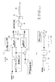
- reference numeral 18 denotes a vehicle sensitivity calculation unit for calculating the reciprocal of vehicle sensitivity (driving force change ⁇ F / accelerator opening change ⁇ ) according to the driving force characteristic map
- 19 denotes an input of the vehicle speed deviation and the reciprocal of the vehicle sensitivity.
- a proportional operation unit that multiplies these by the proportional gain, 20 is an integration operation unit that integrates the output of the proportional operation unit 19, and 21 is an addition unit that adds the output of the proportional operation unit 19 and the output of the integration operation unit 20
- the proportional calculation unit 19, the integration calculation unit 20, and the addition unit 21 constitute a vehicle feedback unit 22.
- the output of the vehicle feedback unit 22 is the accelerator opening.
- reference numeral 23 denotes a driving force characteristic map unit, to which a target driving force and a target vehicle speed are input, and an accelerator opening is output from a driving force characteristic map recorded in advance.
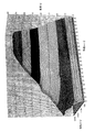
- this driving force characteristic map is a characteristic map of the relationship between the vehicle speed, the driving force, and the accelerator opening.
- the accelerator opening which is the output of the vehicle speed feedback unit 22, is added to the accelerator opening by the adding unit 24, and an accelerator command is obtained.
- the accelerator command is input to the vehicle 39, and the accelerator opening of the vehicle 39 is manipulated.
- the vehicle 39 generates the engine driving force required for the operation mode according to the accelerator opening.
- the vehicle 39 includes a vehicle (engine + drive system) 25, an adding unit 26, and a vehicle (inertia) 27.
- the driving resistance of the chassis dynamometer is reduced in the adding unit 26 from the driving force generated by the vehicle 25.
- the acceleration force is obtained by subtraction, and thereby the vehicle speed is generated from the vehicle 27.
- the input / output characteristics of the vehicle 25 are vehicle sensitivity.
- the vehicle characteristics are canceled by the vehicle sensitivity on the chassis dynamometer and the reciprocal of the vehicle sensitivity calculated by the vehicle sensitivity calculation unit 18, the system is linearized, and the vehicle speed feedback response Is proportional to the vehicle weight and can be determined by an integral (PI) coefficient. If the PI coefficient is also determined according to the vehicle weight, the response of the vehicle speed feedback unit 22 can be made constant.
- PI integral
- the vehicle speed feedback unit 22 When the vehicle sensitivity is low, the vehicle speed feedback unit 22 has a high gain at high speed and high load, the vehicle speed tracking performance can be improved.
- FIG. 2A and 2B show the configuration of the vehicle sensitivity calculation unit 18 and the vehicle speed feedback unit 22 according to a more specific embodiment of the present invention.
- the vehicle sensitivity calculation unit 18 shown in FIG. the command side acceleration force calculation unit 1 receives the vehicle speed command to calculate the acceleration force, and the addition unit 3 adds the running resistance to obtain the required driving force.
- the driving force characteristic unit 28 has a driving force characteristic map of the above-described three-way relation of vehicle speed, driving force, and accelerator opening, and receives the vehicle speed command and the required driving force, and determines the accelerator opening. Output.
- the adding unit 29 adds the driving force change amount ⁇ F, which is a small fixed value to the driving force scale, and the required driving force, and inputs this added value to the driving force characteristic unit 30 together with the vehicle speed command Vs. .
- the driving force characteristic unit 30 also has a driving force characteristic map similar to that of the driving force characteristic unit 28, and the accelerator opening is output.
- the driving force is calculated from the accelerator opening output from the driving force characteristic unit 30.
- the accelerator opening degree output from the characteristic unit 28 is subtracted to obtain the change amount ⁇ of the accelerator opening degree.
- the change amount ⁇ of the accelerator opening and the change amount ⁇ F of the driving force are input to the calculation unit 32, and the inverse number ⁇ / ⁇ F of the vehicle sensitivity is calculated.
- ⁇ / ⁇ F is limited to zero or more.
- the peak hold 34 when the reciprocal of the vehicle sensitivity suddenly decreases from the acceleration to the steady state, this value is kept large for a certain period of time, and a decrease in gain calculated based on this value is suppressed. Improve the convergence.
- the vehicle speed deviation and the output * 1 of the peak hold 34 are input, these values are multiplied, and the proportional calculation unit 19 is multiplied.
- the output of the proportional calculation unit 19 is integrated by the integration calculation unit 20, and is added to the output of the proportional calculation unit 19 by the addition unit 38 to become the accelerator opening output of the vehicle feedback unit 22, and this accelerator opening output is shown in FIG. Is added to the accelerator opening, which is the output of the driving force characteristic map unit 23, and becomes an accelerator opening command.
- the subsequent control operation is the same as in FIG.
- a linear control design theory of a speed control system with inertia (here, vehicle weight) as a control target can be used.
- the parameter is determined as follows: Is applicable. That is, for example, the proportional gain M / T of the proportional computation unit 19 and the integral gain 1 / 4T of the integral computation unit 20.
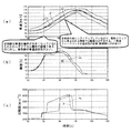
- FIG. 4 (a) shows the relationship between time and vehicle speed.
- A is the command value
- B is the control vehicle speed before improvement
- C is the control vehicle speed after improvement
- the gear is shifted up during steady running.
- the accelerator opening calculated from the driving force map
- the driving force is insufficient, and the following capability of the vehicle speed feedback is required.
- the accelerator operation is slow although the deviation of the vehicle speed is large.
- the vehicle speed tracking is good.
- 4 (b) shows the relationship between time and opening
- FIG. 4 (c) shows the relationship between time and rotational speed. D and F are before improvement, and E and F are after improvement.
- FIG. 1 is a basic configuration diagram according to an embodiment of the present invention. It is a block diagram of the vehicle sensitivity calculating part and vehicle speed feedback part by concrete best mode of this invention. It is a driving force characteristic map by this invention. It is a characteristic view which shows the effect of this invention.
- This is a conventional vehicle speed control device disclosed in Patent Document 1. It is another conventional vehicle speed control apparatus.
Landscapes
- Physics & Mathematics (AREA)
- General Physics & Mathematics (AREA)
- Controls For Constant Speed Travelling (AREA)
- Control Of Vehicle Engines Or Engines For Specific Uses (AREA)
- Electric Propulsion And Braking For Vehicles (AREA)
- Testing Of Engines (AREA)
- Auxiliary Drives, Propulsion Controls, And Safety Devices (AREA)
- Control Of Driving Devices And Active Controlling Of Vehicle (AREA)
- Electrical Control Of Air Or Fuel Supplied To Internal-Combustion Engine (AREA)
Abstract
Description
18…車両感度演算部
19…比例演算部
20…積分演算部
22…車速フィードバック部
23…駆動力特性マップ部
33…リミッタ
34…ピークホールド
39…車両
Claims (2)
- 予め事前に収録された駆動力特性マップを有し、目標駆動力と目標車速が入力され、駆動力特性マップに従ってアクセル開度を出力する駆動力特性マップ部と、前記駆動力特性マップに応じて車両感度の逆数を演算する車両感度演算部と、車速偏差と車両感度の逆数を入力され、車両感度の逆数に応じたアクセル開度を出力する車速フィードバック部と、駆動力特性マップ部からのアクセル開度に車速フィードバック部からのアクセル開度を加算する加算部と、加算部からのアクセル開度指令によりアクセル開度を動かして目標車速に車速を一致させる手段とを備えたことを特徴とする車両速度制御装置。
- 車両感度演算部からの車両感度の逆数が急に小さくなった場合、この値を大きいままで一定時間保持する手段を備えたことを特徴とする請求項1記載の車両速度制御装置。
Priority Applications (3)
| Application Number | Priority Date | Filing Date | Title |
|---|---|---|---|
| US12/933,976 US8812213B2 (en) | 2008-03-25 | 2009-03-04 | Vehicle speed control apparatus |
| KR1020107021739A KR101225516B1 (ko) | 2008-03-25 | 2009-03-04 | 차속제어장치 |
| CN200980110063XA CN101978252B (zh) | 2008-03-25 | 2009-03-04 | 车速控制装置 |
Applications Claiming Priority (2)
| Application Number | Priority Date | Filing Date | Title |
|---|---|---|---|
| JP2008077186A JP5098736B2 (ja) | 2008-03-25 | 2008-03-25 | 車両速度制御装置 |
| JP2008-077186 | 2008-03-25 |
Publications (1)
| Publication Number | Publication Date |
|---|---|
| WO2009119263A1 true WO2009119263A1 (ja) | 2009-10-01 |
Family
ID=41113468
Family Applications (1)
| Application Number | Title | Priority Date | Filing Date |
|---|---|---|---|
| PCT/JP2009/054016 Ceased WO2009119263A1 (ja) | 2008-03-25 | 2009-03-04 | 車両速度制御装置 |
Country Status (6)
| Country | Link |
|---|---|
| US (1) | US8812213B2 (ja) |
| JP (1) | JP5098736B2 (ja) |
| KR (1) | KR101225516B1 (ja) |
| CN (1) | CN101978252B (ja) |
| TW (1) | TWI393872B (ja) |
| WO (1) | WO2009119263A1 (ja) |
Cited By (1)
| Publication number | Priority date | Publication date | Assignee | Title |
|---|---|---|---|---|
| JP2009025064A (ja) * | 2007-07-18 | 2009-02-05 | Meidensha Corp | 車両速度制御における駆動力特性収録方法 |
Families Citing this family (10)
| Publication number | Priority date | Publication date | Assignee | Title |
|---|---|---|---|---|
| US9009475B2 (en) * | 2011-04-05 | 2015-04-14 | Apple Inc. | Apparatus and methods for storing electronic access clients |
| AT512251B1 (de) * | 2013-02-28 | 2014-08-15 | Avl List Gmbh | Verfahren zum Entwerfen eines nichtlinearen Reglers für nichtlineare Prozesse |
| TWI548552B (zh) * | 2014-01-28 | 2016-09-11 | 華創車電技術中心股份有限公司 | 速限控制方法 |
| JP6277060B2 (ja) * | 2014-05-19 | 2018-02-07 | 株式会社小野測器 | スロットル制御装置 |
| JP6429235B2 (ja) * | 2015-02-24 | 2018-11-28 | 株式会社明電舎 | 車両速度制御装置 |
| JP6135741B2 (ja) * | 2015-10-30 | 2017-05-31 | 株式会社明電舎 | 車両試験装置および車両試験装置の車速偏差算出方法 |
| JP6075479B1 (ja) * | 2016-01-28 | 2017-02-08 | 株式会社明電舎 | 車両の自動運転システムおよび自動運転方法 |
| US10306315B2 (en) * | 2016-03-29 | 2019-05-28 | International Business Machines Corporation | Video streaming augmenting |
| EP4134651B1 (en) * | 2020-04-10 | 2026-01-21 | HORIBA, Ltd. | Automatic test subject driving device, automatic test subject driving method, and test subject testing system |
| CN115476844B (zh) * | 2022-07-29 | 2025-07-01 | 江苏徐工工程机械研究院有限公司 | 一种无人矿卡纵向低速平稳控制方法与系统 |
Citations (2)
| Publication number | Priority date | Publication date | Assignee | Title |
|---|---|---|---|---|
| JP2002014009A (ja) * | 2000-06-29 | 2002-01-18 | Nissan Motor Co Ltd | 車両用自動運転装置 |
| JP2005297872A (ja) * | 2004-04-15 | 2005-10-27 | Meidensha Corp | 車両速度制御装置 |
Family Cites Families (21)
| Publication number | Priority date | Publication date | Assignee | Title |
|---|---|---|---|---|
| JP2601289B2 (ja) * | 1987-10-28 | 1997-04-16 | マツダ株式会社 | 車両の定速走行制御装置 |
| JPH04203250A (ja) * | 1990-11-29 | 1992-07-23 | Mitsubishi Motors Corp | 走行負荷分補償式速度制御部付ドライブバイワイヤ式車両 |
| US5532929A (en) * | 1992-12-16 | 1996-07-02 | Toyota Jidosha Kabushiki Kaisha | Apparatus for controlling vehicle driving power |
| JP3508473B2 (ja) * | 1997-06-23 | 2004-03-22 | 株式会社明電舎 | シャシーダイナモメータの走行抵抗制御装置 |
| JP2000104580A (ja) * | 1998-09-30 | 2000-04-11 | Hitachi Ltd | 車両駆動力制御装置 |
| JP3465618B2 (ja) * | 1999-03-08 | 2003-11-10 | 日産自動車株式会社 | 車両の駆動力制御装置 |
| JP3520915B2 (ja) * | 2000-09-19 | 2004-04-19 | 日産自動車株式会社 | 4輪駆動車の前後輪トルク配分制御装置 |
| JP3666391B2 (ja) * | 2000-12-26 | 2005-06-29 | 日産自動車株式会社 | 駆動力制御装置 |
| JP4489333B2 (ja) * | 2001-09-26 | 2010-06-23 | 日産自動車株式会社 | 車両の駆動力制御装置 |
| JP2003237421A (ja) * | 2002-02-18 | 2003-08-27 | Nissan Motor Co Ltd | 車両の駆動力制御装置 |
| DE60306024T2 (de) * | 2002-04-26 | 2007-01-04 | Jtekt Corp. | Verfahren und System zur Antriebskraftverteilung für ein Kraftfahrzeug mit Allradantrieb |
| JP2003327013A (ja) * | 2002-05-16 | 2003-11-19 | Nissan Motor Co Ltd | 車両の駆動力制御装置 |
| JP3977701B2 (ja) * | 2002-07-17 | 2007-09-19 | 日野自動車株式会社 | アクセル制御装置 |
| EP1415850A3 (en) * | 2002-10-31 | 2006-05-10 | Toyoda Koki Kabushiki Kaisha | Torque distribution control device for four-wheel drive vehicle |
| JP4005483B2 (ja) * | 2002-11-20 | 2007-11-07 | 日産自動車株式会社 | 車線逸脱防止装置 |
| JP2005113734A (ja) * | 2003-10-06 | 2005-04-28 | Hino Motors Ltd | アクセル制御装置 |
| JP4296957B2 (ja) * | 2004-02-18 | 2009-07-15 | トヨタ自動車株式会社 | 車両用無段変速機の制御装置 |
| JP5201786B2 (ja) * | 2005-07-19 | 2013-06-05 | 日産自動車株式会社 | エンジン出力制御装置 |
| JP4432861B2 (ja) * | 2005-08-22 | 2010-03-17 | トヨタ自動車株式会社 | 車両の駆動力制御装置 |
| JP4788611B2 (ja) * | 2006-03-10 | 2011-10-05 | 日産自動車株式会社 | 車間維持支援装置および車間維持支援方法 |
| JP4788464B2 (ja) * | 2006-04-28 | 2011-10-05 | 日産自動車株式会社 | 車間維持支援装置および車間維持支援方法 |
-
2008
- 2008-03-25 JP JP2008077186A patent/JP5098736B2/ja active Active
-
2009
- 2009-03-04 WO PCT/JP2009/054016 patent/WO2009119263A1/ja not_active Ceased
- 2009-03-04 CN CN200980110063XA patent/CN101978252B/zh active Active
- 2009-03-04 KR KR1020107021739A patent/KR101225516B1/ko active Active
- 2009-03-04 US US12/933,976 patent/US8812213B2/en active Active
- 2009-03-12 TW TW098108052A patent/TWI393872B/zh active
Patent Citations (2)
| Publication number | Priority date | Publication date | Assignee | Title |
|---|---|---|---|---|
| JP2002014009A (ja) * | 2000-06-29 | 2002-01-18 | Nissan Motor Co Ltd | 車両用自動運転装置 |
| JP2005297872A (ja) * | 2004-04-15 | 2005-10-27 | Meidensha Corp | 車両速度制御装置 |
Cited By (1)
| Publication number | Priority date | Publication date | Assignee | Title |
|---|---|---|---|---|
| JP2009025064A (ja) * | 2007-07-18 | 2009-02-05 | Meidensha Corp | 車両速度制御における駆動力特性収録方法 |
Also Published As
| Publication number | Publication date |
|---|---|
| CN101978252A (zh) | 2011-02-16 |
| JP2009227186A (ja) | 2009-10-08 |
| TW200942797A (en) | 2009-10-16 |
| KR20100126457A (ko) | 2010-12-01 |
| CN101978252B (zh) | 2013-03-13 |
| JP5098736B2 (ja) | 2012-12-12 |
| US20110015847A1 (en) | 2011-01-20 |
| US8812213B2 (en) | 2014-08-19 |
| TWI393872B (zh) | 2013-04-21 |
| KR101225516B1 (ko) | 2013-01-23 |
Similar Documents
| Publication | Publication Date | Title |
|---|---|---|
| JP5098736B2 (ja) | 車両速度制御装置 | |
| US8364368B2 (en) | Acceleration control apparatus for vehicle | |
| KR100618335B1 (ko) | 차량속도제어시스템 | |
| KR101521487B1 (ko) | 동력계 시스템 | |
| JP5250541B2 (ja) | 電動車両の差動制限制御装置 | |
| JP6289993B2 (ja) | 変速機クラッチトルク推定方法 | |
| JP3873584B2 (ja) | 車両用自動運転装置 | |
| CA2631627A1 (en) | Vehicle control device | |
| JP6235420B2 (ja) | 車速指令生成装置及び車速指令生成方法 | |
| JP6429235B2 (ja) | 車両速度制御装置 | |
| JP5866982B2 (ja) | トランスミッション試験装置 | |
| JPH0666682A (ja) | ブレーキダイナモシステムの制御方法 | |
| JP5880048B2 (ja) | 電動車両の制御方法及び電動車両の制御装置 | |
| JP2794423B2 (ja) | 車両駆動系制御装置および制御方法 | |
| KR101780700B1 (ko) | 전동식 조향 장치의 제어 장치 및 방법 | |
| JP4591177B2 (ja) | エンジン試験装置 | |
| JPH07325019A (ja) | 車両速度制御装置 | |
| KR20170080420A (ko) | 전동식 조향 장치의 제어 장치 및 방법 | |
| JP5277790B2 (ja) | 慣性モーメント同定器を備えたモータ制御装置 | |
| WO2015186616A1 (ja) | シャシーダイナモメータの制御装置 | |
| JP2010261571A (ja) | ロックアップクラッチの制御装置 | |
| JP2011147268A (ja) | モータ制御装置 | |
| JP5812229B1 (ja) | シャシーダイナモメータの制御装置 | |
| KR20190029812A (ko) | 차량의 클러치 제어방법 | |
| JP2007221937A (ja) | システム同定装置およびそのシステム同定方法 |
Legal Events
| Date | Code | Title | Description |
|---|---|---|---|
| WWE | Wipo information: entry into national phase |
Ref document number: 200980110063.X Country of ref document: CN |
|
| 121 | Ep: the epo has been informed by wipo that ep was designated in this application |
Ref document number: 09725587 Country of ref document: EP Kind code of ref document: A1 |
|
| WWE | Wipo information: entry into national phase |
Ref document number: 12933976 Country of ref document: US |
|
| NENP | Non-entry into the national phase |
Ref country code: DE |
|
| ENP | Entry into the national phase |
Ref document number: 20107021739 Country of ref document: KR Kind code of ref document: A |
|
| 122 | Ep: pct application non-entry in european phase |
Ref document number: 09725587 Country of ref document: EP Kind code of ref document: A1 |