WO2009116236A1 - 揺動歯車装置 - Google Patents
揺動歯車装置 Download PDFInfo
- Publication number
- WO2009116236A1 WO2009116236A1 PCT/JP2009/000943 JP2009000943W WO2009116236A1 WO 2009116236 A1 WO2009116236 A1 WO 2009116236A1 JP 2009000943 W JP2009000943 W JP 2009000943W WO 2009116236 A1 WO2009116236 A1 WO 2009116236A1
- Authority
- WO
- WIPO (PCT)
- Prior art keywords
- gear
- flexible external
- external gear
- rigid internal
- eccentric
- Prior art date
- Legal status (The legal status is an assumption and is not a legal conclusion. Google has not performed a legal analysis and makes no representation as to the accuracy of the status listed.)
- Ceased
Links
Images


Classifications
-
- F—MECHANICAL ENGINEERING; LIGHTING; HEATING; WEAPONS; BLASTING
- F16—ENGINEERING ELEMENTS AND UNITS; GENERAL MEASURES FOR PRODUCING AND MAINTAINING EFFECTIVE FUNCTIONING OF MACHINES OR INSTALLATIONS; THERMAL INSULATION IN GENERAL
- F16H—GEARING
- F16H49/00—Other gearings
- F16H49/001—Wave gearings, e.g. harmonic drive transmissions
-
- F—MECHANICAL ENGINEERING; LIGHTING; HEATING; WEAPONS; BLASTING
- F16—ENGINEERING ELEMENTS AND UNITS; GENERAL MEASURES FOR PRODUCING AND MAINTAINING EFFECTIVE FUNCTIONING OF MACHINES OR INSTALLATIONS; THERMAL INSULATION IN GENERAL
- F16H—GEARING
- F16H49/00—Other gearings
- F16H2049/006—Wave generators producing a non-elliptical shape of flexsplines, i.e. with a qualified different shape than elliptical
Definitions
- the present invention relates to an oscillating gear device, and more particularly, a high accuracy, high reduction ratio used in a robot, a machine tool, a liquid crystal / semiconductor manufacturing apparatus, etc. that require high positioning accuracy, smooth rotation and quietness.
- the present invention relates to a rocking gear device having
- a wave gear device is known as a gear device that is lightweight, compact, and capable of obtaining high accuracy and a high reduction ratio without using a complicated mechanism / structure.
- the wave gear device partially meshes an elastic flexible meshing external gear with an annular rigid internal gear and uses the elastic flexibility to change the meshing position.
- a structure having a wave generator that moves in the circumferential direction by a difference in the number of teeth of both gears is representative. (See Patent Document 1).
- a typical wave gear device includes, as a specific configuration, an annular rigid internal gear, a cup-shaped flexible external gear disposed on the inside, and an elliptical wave fitted on the inside. And a generator.
- the flexible external gear is bent into an elliptical shape by a wave generator, and the external teeth at both ends of the long axis direction of the elliptical shape mesh with the internal teeth formed on the inner peripheral surface of the internal gear. Yes.
- the wave generator is rotated by a motor rotating shaft or the like, the meshing position of both gears moves in the circumferential direction.
- the internal gear side is fixed, rotation that is greatly decelerated according to the difference in the number of teeth of both gears is output from the cup-shaped flexible external gear side.
- the wave generator includes a cam portion and a bearing formed in an elliptical shape.
- the cam portion serves to partially mesh the internal teeth of the rigid internal gear by bending the external teeth of the flexible external gear in the radial direction.
- the bearing has a ball, an inner ring, and an outer ring.
- the inner ring is fixed to the outer periphery of the cam portion, and the outer ring is fitted to the back side of the outer teeth of the flexible external gear, and is elastically deformed in accordance with the flexible external gear by the rotation of the cam portion.
- the conventional typical wave gear device has a problem that a commercially available bearing cannot be used because the wave generator uses a special bearing whose inner ring is elliptical and whose outer ring is elastically deformable.
- the outer ring of the bearing is thin, when the overload is applied, the rigid inner gear and the flexible external gear are caused by the bending of the outer ring that occurs between the balls of the bearing. There is a possibility that a ratcheting phenomenon occurs in which the meshing momentarily shifts.
- the length of the long axis of the cam portion of the wave generator on the high speed rotation side has a large ratio to the inner diameter of the rigid internal gear, the moment of inertia tends to increase.
- An object of the present invention is to provide a gear device that can use a commercially available bearing, does not cause a ratcheting phenomenon even when an overload is applied, and can reduce the moment of inertia on the high-speed rotation side.
- an oscillating gear device of the present invention includes an annular rigid internal gear, an annular flexible external gear disposed inside the rigid internal gear, and the flexibility.
- a swing generator fitted inside the external gear, the flexible external gear is bent, and the two gears are partially connected at two positions facing each other across the center of the rigid internal gear.
- the swing generator includes a circular contour eccentric cam that rotates eccentrically around a rotation axis of the swing generator, a bearing fitted on an outer periphery of the eccentric cam, Two eccentric rollers having a circular contour provided with wheels arranged on the outer periphery; Are arranged so that the center of the circular contour of each eccentric roller is located at a predetermined distance away from the rotation shaft in the opposite direction, and the outer peripheral surface of the eccentric roller is the flexible outer tooth.
- the oscillating gear device of the present invention includes an annular rigid internal gear, an annular flexible external gear disposed inside the rigid internal gear, and the movable gear.
- a swing generator fitted inside the flexible external gear, the flexible external gear is bent, and both of the two internal parts are opposed to each other across the center of the rigid internal gear. Engaging the gears and moving the meshing position of both gears in the circumferential direction by the rotation of the oscillation generator, the oscillation causing relative rotation between the rigid internal gear and the flexible external gear.
- the swing generator includes a circular contour eccentric cam that rotates eccentrically about a rotation axis of the swing generator, a bearing fitted on an outer periphery of the eccentric cam, Two eccentric rollers with a circular contour comprising a wheel arranged on the outer periphery of the bearing, The center rollers are arranged so that the centers of the circular contours of the eccentric rollers are spaced apart from each other by the predetermined amount from the rotation shaft, and the outer circumferential surface of the eccentric roller is the flexible outer surface.
- the flexible external gear By contacting the inner peripheral surface of the toothed gear, the flexible external gear so that the central portion of the tooth width of the flexible external gear and the rigid internal gear partially mesh with each other at the two locations.
- the eccentric cam has a circular contour, and it is not necessary to use a special bearing having an elliptical inner ring and an elastically deformable outer ring. Therefore, a commercially available bearing is used as a bearing that fits on the outer periphery of the eccentric cam. can do.
- the eccentric roller has a wheel on the outer periphery of the bearing, and the outer peripheral surface of the wheel contacts the inner peripheral surface of the flexible external gear, so that it can be elastically deformed on the back surface of the external tooth of the flexible external gear. It is not necessary to use a bearing having a thin outer ring, and it is possible to suppress the occurrence of a ratcheting phenomenon due to bending of the thin outer ring that can be elastically deformed.
- the swing generator has two eccentric rollers, and is arranged so that the centers of the circular contours of the eccentric rollers are positioned a predetermined amount away from each other in the opposite directions from the rotation shaft.
- the oscillating gear device of the present invention it is possible to use a commercially available bearing, and to provide a gear device capable of reducing the moment of inertia on the high-speed rotation side without causing ratcheting phenomenon even when an overload is applied. be able to.
- FIG. 3 is a sectional view taken along line AA in FIG. 2. It is explanatory drawing which shows typically the arrangement
- FIG. 4B is a side view of the flexible external gear after deformation.
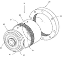
- FIG. 1 is an exploded perspective view of a rocking gear device according to an embodiment of the present invention.
- the oscillating gear device 10 includes an annular rigid internal gear 20, an annular flexible external gear 30 that can be elastically deformed, and an oscillation generator 40.
- the rigid internal gear 20 includes an internal tooth portion 21 formed on the inner peripheral surface and a fixing bolt hole 22 for fixing the rigid internal gear 20 to a fixing member (not shown).
- the flexible external gear 30 has a cup shape, and an output rotating shaft mounting bolt for connection to an external tooth portion 31 formed on the outer peripheral surface of the cup on the opening side and an output rotating shaft (not shown). And a hole 33.
- the external teeth 31 are formed with external teeth having a tooth width WW.
- the swing generator 40 includes two eccentric rollers 41 and an input rotating shaft mounting portion 45.
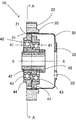
- FIG. 2 is a cross-sectional view of the oscillating gear device according to the embodiment of the present invention, and includes a rotation shaft of the oscillation generator and a long axis of the flexible external gear bent by the oscillation generator. It is sectional drawing in a plane.
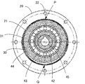
- 3 is a cross-sectional view taken along line AA in FIG.
- the oscillating gear device 10 has a flexible external gear 30 disposed inside a rigid internal gear 20, and a oscillating generator inside the flexible external gear 30. 40 is inserted to bend the flexible external gear 30, thereby forming the internal teeth formed on the internal tooth portion 21 of the rigid internal gear 20 and the external tooth portion 31 of the flexible external gear 30.
- These external teeth are configured to mesh with each other at two positions facing each other across the center of the rigid internal gear 20, that is, meshing positions P and Q.
- the rigid internal gear 20 is formed of a rigid body.
- the flexible external gear 30 may be entirely formed of a flexible material, but is formed of a flexible material except at least the output rotation shaft mounting portion 32 provided annularly on the cup-shaped bottom surface. And is formed thin so as to be elastically deformable.
- the output rotating shaft mounting portion 32 is formed thicker than other portions, and is provided with an output rotating shaft mounting bolt hole 33.
- the external tooth part 31 is also comprised so that elastic deformation is possible.
- the swing generator 40 has two eccentric rollers 41 having a circular contour.
- the eccentric roller 41 is arranged on a circular contour eccentric cam 42 that rotates eccentrically around a rotation axis XX of the swing generator, a bearing 43 fitted on the outer periphery of the eccentric cam 42, and an outer periphery of the bearing 43. And a wheel 44.
- the eccentric cam 42 is fixed to the input rotating shaft mounting portion 45.
- FIG. 4 is an explanatory view schematically showing an arrangement state of two eccentric rollers.
- the two eccentric rollers 41 are arranged such that the center 41 a of the circular contour of each eccentric roller is located a predetermined amount ( ⁇ ) away from the rotation axis XX of the swing generator 40 in the opposite directions. , Are arranged in layers. Since the swing generator 40 has such a shape, when the swing generator 40 is fitted inside the flexible external gear 30, the outer peripheral surface of the eccentric roller 41 becomes the flexible external gear. 30, the flexible external gear 30 bends in contact with the inner peripheral surface of the external tooth portion 31, and the external teeth of the flexible external gear 30 are the internal teeth of the rigid internal gear 20 and the rigid internal gear 20. Are engaged at two opposite locations (see FIG. 3).
- the oscillating gear device 10 of the present embodiment is different from the wave generator having the elliptical cam and the bearing having the elastically deformable outer ring of the conventional wave gear device, having two circular outlines.
- a motion generator 40 is provided. Therefore, in the oscillating gear device 10 of this embodiment, the eccentric cam 42 used for the eccentric roller 41 has a circular contour, and it is not necessary to use a special bearing having an elliptical inner ring and an elastically deformable outer ring.
- a commercially available bearing can be used for the bearing 43 fitted to the outer periphery of the eccentric cam 42. Further, since it is not necessary to use a bearing having a thin outer ring that can be elastically deformed on the back surface of the external teeth of the flexible external gear 30, by providing a wheel 44 outside the bearing 43, a thin wall that can be elastically deformed is provided. Occurrence of the ratcheting phenomenon due to the bending of the outer ring can be suppressed. Furthermore, since the ratio of the diameter of the eccentric cam 42 to the diameter of the rigid internal gear 20 is small, the moment of inertia on the high speed rotation side can be reduced.
- FIG. 5 is an explanatory diagram of the operation of the oscillating gear device according to the embodiment of the present invention.
- the swing generator 10 of the present embodiment when the input rotation shaft is attached to the input rotation shaft mounting portion 45 of the swing generator 40 and driven by a motor or the like, the swing generator 40 starts rotating.
- the internal teeth indicated by diagonal lines of the rigid internal gear 20 and the external teeth indicated by black of the flexible external gear 30 mesh with each other.
- the swing generator 40 rotates 90 degrees, the meshing position moves 90 degrees in the circumferential direction. Since the difference between the number of teeth of the internal gear 20 of the rigid internal gear 20 and the number of teeth of the external gear 30 of the flexible external gear 30 is two in the rocking gear device 10 of the present embodiment, the rocking generator 40 is engaged.
- the flexible external gear 30 In order for the meshing position to return to the internal teeth indicated by the diagonal lines of the rigid internal gear 20, the flexible external gear 30 has two external teeth plus two teeth. Must rotate for minutes.
- the swing generator 40 rotates 360 degrees
- the external teeth adjacent to the external teeth shown in black are meshed with the internal teeth shown in diagonal lines.
- the flexible external gear 30 rotates relative to the rotation direction of the oscillation generator 40 by the number of teeth of two sheets.
- the rigid internal gear 20 is fixed so as not to rotate relatively, so that the flexible external gear 30 is greatly changed according to the number of teeth between the internal teeth and the external teeth. It is possible to output the decelerated rotation.
- the swing generator 40 is fitted inside the flexible external gear 30, and the outer peripheral surface of the eccentric roller 41 comes into contact with the inner peripheral surface of the flexible external gear 30.
- the curvature radius R of the meshed position of the flexible external gear 30 is as follows. Expressions (1) and (2) are satisfied.
- FIG. 6 is an explanatory diagram showing the relationship between the pitch circle of the rigid internal gear of the oscillating gear device according to the embodiment of the present invention and the outline of the meshing position of the deformed flexible external gear.
- the pitch circle 211 of the rigid internal gear 20 is circular, and the diameter thereof is equal to the number of teeth Zc of the rigid internal gear 20 as shown on the right side of the above formula (1). Multiply by module m.
- the swing generator 40 is fitted inside the flexible external gear 30 so that the external teeth of the flexible external gear 30 and the internal teeth of the rigid internal gear 20 are in meshing position P and meshing position Q.
- the outline of the meshing position of the flexible external gear 30 in the state of meshing at these two locations is shown in FIG. 6 as the outline 312 of the meshing position of the flexible external gear 30 after deformation.
- the length of the major axis of the meshing position outline 312 of the flexible external gear 30 after deformation that is, the distance between the meshing positions P and Q is determined by the pitch circle of the rigid internal gear 20. Equal to the diameter of 211.
- the distance between the PQs can be obtained as the left side of the above equation (1) using the curvature radius R of the meshing position and the amount of eccentricity ⁇ . Therefore, the curvature radius R of the meshing position of the flexible external gear 30 satisfies the above formula (1).
- the flexible external gear 30 meshes in a deformed state, that is, in a state where the external teeth are inclined with respect to the internal teeth.
- the contour 312 of the meshing position of the deformed flexible external gear 30 normally matches the contour of the central portion of the tooth width WW of the deformed flexible external gear 30.
- FIG. 7 is an explanatory diagram showing the outline of the meshing position before and after the deformation of the flexible external gear of the rocking gear device according to the embodiment of the present invention.
- the pitch circle 311 of the flexible external gear 30 before deformation is circular, and the length of this contour (circumference).
- the number of teeth Zf of the flexible external gear 30 and the module m of this gear is shown on the right side of the above equation (2).
- the contour 312 of the meshing position of the flexible external gear 30 after the deformation is as shown in FIG. 7, but the length of the contour of the meshing position of the flexible external gear 30 changes before and after the deformation. Therefore, the left side of the equation (2) in which the length of the contour 312 of the meshing position of the flexible external gear 30 after deformation is expressed using the curvature radius R and the eccentricity ⁇ of the meshing position, and the deformation Naturally, the right side of the expression (2) in which the circumference of the pitch circle 311 of the previous flexible external gear 30 is expressed using the number of teeth Zf and the module m is equal. Therefore, the curvature radius R of the meshing position of the flexible external gear 30 satisfies the above formula (2).
- the curvature radius R of the meshing position of the flexible external gear 30 satisfies the above formulas (1) and (2).
- the swing generator 40 is fitted inside the flexible external gear 30, and the outer peripheral surface of the eccentric roller 41 comes into contact with the inner peripheral surface of the flexible external gear 30.
- the flexible external gear 30 is bent so that the central portion of the 30 tooth width WW and the rigid internal gear 20 are partially meshed at two locations, the rigid internal gear is not meshed.
- the radius of curvature R 0 and the amount of eccentricity ⁇ 0 of the virtual opening of the flexible external gear 30 satisfy the following expressions (3) and (4).
- the swing generator 40 is fitted inside the flexible external gear 30, and the outer peripheral surface of the eccentric roller 41 comes into contact with the inner peripheral surface of the flexible external gear 30.
- the flexible external gear 30 is bent so that the gear 30 partially meshes with the rigid internal gear 20, and the curvature radius R of the meshed position of the flexible external gear 30 is expressed by the above formulas (1) and (2 ),
- the quantity ⁇ 0 means that the above expressions (3) and (4) are satisfied.
- FIG. 8A illustrates the relationship between the meshing position of the flexible external gear and the contour of the opening and the pitch circle of the rigid internal gear after the deformation of the oscillating gear device according to the embodiment of the present invention. It is a figure, (b) is a side view of the flexible external gear after a deformation
- the curvature radius R 0 of the contour 313 of the opening of the flexible external gear 30 after deformation is smaller than the curvature radius R of the meshing position, and the eccentricity ⁇ 0 is larger than the eccentricity ⁇ of the meshing position. Therefore, the length of the major axis of the contour 313 of the opening of the flexible external gear 30 after deformation can be obtained from R 0 and ⁇ 0 as in the left side of Expression (3). Further, the length of the major axis of the contour 313 of the opening of the flexible external gear 30 after the deformation is from the pitch circle 211 of the rigid internal gear 20 of the opening of the flexible external gear 30 after the deformation.
- the opening of the deformed flexible external gear 30 that satisfies the above formulas (3) and (4) has the rigid internal gear 20 in the deformed flexible external gear 30 as described above. Since it is a virtual opening when it is assumed that the mesh is not meshed, and the rigid internal gear 20 is actually meshed, the contour 313 of the opening of the flexible external gear 30 after deformation is the rigid internal gear 20.
- the portion protruding from the pitch circle 211 that is, the arc portion between the two points shown as the meshing branch point 212 in FIG. 8A is in an interference state, and the entire portion of the opening portion of the flexible external gear 30 is rigid.
Landscapes
- Engineering & Computer Science (AREA)
- General Engineering & Computer Science (AREA)
- Mechanical Engineering (AREA)
- Retarders (AREA)
Applications Claiming Priority (2)
| Application Number | Priority Date | Filing Date | Title |
|---|---|---|---|
| JP2008068776A JP2009222168A (ja) | 2008-03-18 | 2008-03-18 | 揺動歯車装置 |
| JP2008-068776 | 2008-03-18 |
Publications (1)
| Publication Number | Publication Date |
|---|---|
| WO2009116236A1 true WO2009116236A1 (ja) | 2009-09-24 |
Family
ID=41090651
Family Applications (1)
| Application Number | Title | Priority Date | Filing Date |
|---|---|---|---|
| PCT/JP2009/000943 Ceased WO2009116236A1 (ja) | 2008-03-18 | 2009-03-02 | 揺動歯車装置 |
Country Status (3)
| Country | Link |
|---|---|
| JP (1) | JP2009222168A (https=) |
| TW (1) | TW200942713A (https=) |
| WO (1) | WO2009116236A1 (https=) |
Cited By (1)
| Publication number | Priority date | Publication date | Assignee | Title |
|---|---|---|---|---|
| CN111911609A (zh) * | 2019-05-10 | 2020-11-10 | 纳博特斯克有限公司 | 波动齿轮装置 |
Families Citing this family (9)
| Publication number | Priority date | Publication date | Assignee | Title |
|---|---|---|---|---|
| JP5256249B2 (ja) * | 2010-06-18 | 2013-08-07 | 住友重機械工業株式会社 | 撓み噛合い式歯車装置 |
| JP5950649B2 (ja) | 2012-03-23 | 2016-07-13 | キヤノン株式会社 | 波動歯車装置 |
| TWI513925B (zh) * | 2014-06-16 | 2015-12-21 | Hiwin Tech Corp | Can improve the bite rate of the harmonic reducer |
| JP6218690B2 (ja) | 2014-07-23 | 2017-10-25 | 株式会社ハーモニック・ドライブ・システムズ | デュアルタイプの波動歯車装置 |
| CN104595425A (zh) * | 2014-12-18 | 2015-05-06 | 陕西渭河工模具有限公司 | 短筒柔轮谐波减速器 |
| CN107110301A (zh) * | 2015-01-08 | 2017-08-29 | 谐波传动系统有限公司 | 波动发生器及波动齿轮装置 |
| EP3321540B1 (en) * | 2015-07-07 | 2020-04-08 | Harmonic Drive Systems Inc. | Rotation transmission mechanism provided with strain-wave gearing |
| CN106382339B (zh) * | 2016-10-25 | 2019-06-25 | 北京新立机械有限责任公司 | 一种谐波减速器 |
| JP7081878B2 (ja) * | 2018-05-11 | 2022-06-07 | 日本電産シンポ株式会社 | 波動歯車装置 |
Citations (5)
| Publication number | Priority date | Publication date | Assignee | Title |
|---|---|---|---|---|
| JPS6014634A (ja) * | 1983-06-23 | 1985-01-25 | テイジン・セイキ・ボストン・インコーポレーテッド | 歪曲波形伝動組立体 |
| JPH05164198A (ja) * | 1991-12-17 | 1993-06-29 | Hitachi Ltd | ハーモニックドライブ装置 |
| JPH08296702A (ja) * | 1995-04-26 | 1996-11-12 | Japan Servo Co Ltd | 調和形減速機構 |
| JPH1194030A (ja) * | 1997-09-18 | 1999-04-09 | Riraiaru:Kk | 金属隔壁による密封機能を備えた動力伝達機構 |
| JP2007205450A (ja) * | 2006-02-01 | 2007-08-16 | Mitsubishi Heavy Ind Ltd | 減速機の構造 |
-
2008
- 2008-03-18 JP JP2008068776A patent/JP2009222168A/ja not_active Withdrawn
-
2009
- 2009-02-25 TW TW98105982A patent/TW200942713A/zh not_active IP Right Cessation
- 2009-03-02 WO PCT/JP2009/000943 patent/WO2009116236A1/ja not_active Ceased
Patent Citations (5)
| Publication number | Priority date | Publication date | Assignee | Title |
|---|---|---|---|---|
| JPS6014634A (ja) * | 1983-06-23 | 1985-01-25 | テイジン・セイキ・ボストン・インコーポレーテッド | 歪曲波形伝動組立体 |
| JPH05164198A (ja) * | 1991-12-17 | 1993-06-29 | Hitachi Ltd | ハーモニックドライブ装置 |
| JPH08296702A (ja) * | 1995-04-26 | 1996-11-12 | Japan Servo Co Ltd | 調和形減速機構 |
| JPH1194030A (ja) * | 1997-09-18 | 1999-04-09 | Riraiaru:Kk | 金属隔壁による密封機能を備えた動力伝達機構 |
| JP2007205450A (ja) * | 2006-02-01 | 2007-08-16 | Mitsubishi Heavy Ind Ltd | 減速機の構造 |
Cited By (2)
| Publication number | Priority date | Publication date | Assignee | Title |
|---|---|---|---|---|
| CN111911609A (zh) * | 2019-05-10 | 2020-11-10 | 纳博特斯克有限公司 | 波动齿轮装置 |
| CN111911609B (zh) * | 2019-05-10 | 2024-05-28 | 纳博特斯克有限公司 | 波动齿轮装置 |
Also Published As
| Publication number | Publication date |
|---|---|
| TWI359236B (https=) | 2012-03-01 |
| TW200942713A (en) | 2009-10-16 |
| JP2009222168A (ja) | 2009-10-01 |
Similar Documents
| Publication | Publication Date | Title |
|---|---|---|
| WO2009116236A1 (ja) | 揺動歯車装置 | |
| KR100854517B1 (ko) | 파동 기어 장치 | |
| JP5256249B2 (ja) | 撓み噛合い式歯車装置 | |
| US20110245006A1 (en) | Strain wave gearing and robotic arm | |
| JP7450776B2 (ja) | 歯車装置 | |
| WO2018198348A1 (ja) | 波動歯車装置および波動発生器 | |
| JP7506967B2 (ja) | 歯車ユニット | |
| US20200018380A1 (en) | Gear device | |
| JP2011021729A (ja) | 撓み噛合い式歯車装置及び撓み噛合い式歯車装置の歯形の決定方法 | |
| JP2021021422A (ja) | 波動歯車装置 | |
| JP5475153B2 (ja) | 撓み噛合い式歯車装置 | |
| JP6921469B2 (ja) | コロ軸受式波動発生器を備えた波動歯車装置 | |
| CN102691753A (zh) | 减速器、机器人手以及机器人 | |
| JP2022030120A (ja) | シール部材、及び、回転機器 | |
| JP5139854B2 (ja) | 揺動歯車装置およびこれを備えるユニット型歯車装置ならびにその組立方法 | |
| JP2020203363A5 (https=) | ||
| JP2004044685A (ja) | 内接噛合遊星歯車機構 | |
| JP7103614B2 (ja) | 波動歯車装置 | |
| US12158201B2 (en) | Internal meshing type gear device | |
| JP5310424B2 (ja) | 撓み噛み合い式歯車装置 | |
| JP6587005B2 (ja) | タイミングベルト差動機構 | |
| WO2020170297A1 (ja) | 遊星歯車装置 | |
| JP2015021555A (ja) | 偏心揺動型歯車装置 | |
| JPH09303499A (ja) | 低減速比の撓み噛み合い式歯車装置 | |
| KR20120116794A (ko) | 내접요동 감속기 |
Legal Events
| Date | Code | Title | Description |
|---|---|---|---|
| 121 | Ep: the epo has been informed by wipo that ep was designated in this application |
Ref document number: 09721335 Country of ref document: EP Kind code of ref document: A1 |
|
| NENP | Non-entry into the national phase |
Ref country code: DE |
|
| 122 | Ep: pct application non-entry in european phase |
Ref document number: 09721335 Country of ref document: EP Kind code of ref document: A1 |