WO2006057243A1 - 光拡散シート及び透過型スクリーン - Google Patents
光拡散シート及び透過型スクリーン Download PDFInfo
- Publication number
- WO2006057243A1 WO2006057243A1 PCT/JP2005/021447 JP2005021447W WO2006057243A1 WO 2006057243 A1 WO2006057243 A1 WO 2006057243A1 JP 2005021447 W JP2005021447 W JP 2005021447W WO 2006057243 A1 WO2006057243 A1 WO 2006057243A1
- Authority
- WO
- WIPO (PCT)
- Prior art keywords
- light
- light diffusing
- sheet
- light diffusion
- diffusion sheet
- Prior art date
- Legal status (The legal status is an assumption and is not a legal conclusion. Google has not performed a legal analysis and makes no representation as to the accuracy of the status listed.)
- Ceased
Links
Classifications
-
- G—PHYSICS
- G02—OPTICS
- G02B—OPTICAL ELEMENTS, SYSTEMS OR APPARATUS
- G02B5/00—Optical elements other than lenses
- G02B5/02—Diffusing elements; Afocal elements
- G02B5/0205—Diffusing elements; Afocal elements characterised by the diffusing properties
- G02B5/021—Diffusing elements; Afocal elements characterised by the diffusing properties the diffusion taking place at the element's surface, e.g. by means of surface roughening or microprismatic structures
- G02B5/0221—Diffusing elements; Afocal elements characterised by the diffusing properties the diffusion taking place at the element's surface, e.g. by means of surface roughening or microprismatic structures the surface having an irregular structure
-
- G—PHYSICS
- G02—OPTICS
- G02B—OPTICAL ELEMENTS, SYSTEMS OR APPARATUS
- G02B5/00—Optical elements other than lenses
- G02B5/02—Diffusing elements; Afocal elements
-
- G—PHYSICS
- G02—OPTICS
- G02B—OPTICAL ELEMENTS, SYSTEMS OR APPARATUS
- G02B5/00—Optical elements other than lenses
- G02B5/02—Diffusing elements; Afocal elements
- G02B5/0205—Diffusing elements; Afocal elements characterised by the diffusing properties
- G02B5/021—Diffusing elements; Afocal elements characterised by the diffusing properties the diffusion taking place at the element's surface, e.g. by means of surface roughening or microprismatic structures
- G02B5/0226—Diffusing elements; Afocal elements characterised by the diffusing properties the diffusion taking place at the element's surface, e.g. by means of surface roughening or microprismatic structures having particles on the surface
-
- G—PHYSICS
- G02—OPTICS
- G02B—OPTICAL ELEMENTS, SYSTEMS OR APPARATUS
- G02B5/00—Optical elements other than lenses
- G02B5/02—Diffusing elements; Afocal elements
- G02B5/0205—Diffusing elements; Afocal elements characterised by the diffusing properties
- G02B5/0236—Diffusing elements; Afocal elements characterised by the diffusing properties the diffusion taking place within the volume of the element
- G02B5/0242—Diffusing elements; Afocal elements characterised by the diffusing properties the diffusion taking place within the volume of the element by means of dispersed particles
-
- G—PHYSICS
- G02—OPTICS
- G02B—OPTICAL ELEMENTS, SYSTEMS OR APPARATUS
- G02B5/00—Optical elements other than lenses
- G02B5/02—Diffusing elements; Afocal elements
- G02B5/0273—Diffusing elements; Afocal elements characterized by the use
- G02B5/0278—Diffusing elements; Afocal elements characterized by the use used in transmission
-
- G—PHYSICS
- G03—PHOTOGRAPHY; CINEMATOGRAPHY; ANALOGOUS TECHNIQUES USING WAVES OTHER THAN OPTICAL WAVES; ELECTROGRAPHY; HOLOGRAPHY
- G03B—APPARATUS OR ARRANGEMENTS FOR TAKING PHOTOGRAPHS OR FOR PROJECTING OR VIEWING THEM; APPARATUS OR ARRANGEMENTS EMPLOYING ANALOGOUS TECHNIQUES USING WAVES OTHER THAN OPTICAL WAVES; ACCESSORIES THEREFOR
- G03B21/00—Projectors or projection-type viewers; Accessories therefor
- G03B21/10—Projectors with built-in or built-on screen
-
- G—PHYSICS
- G03—PHOTOGRAPHY; CINEMATOGRAPHY; ANALOGOUS TECHNIQUES USING WAVES OTHER THAN OPTICAL WAVES; ELECTROGRAPHY; HOLOGRAPHY
- G03B—APPARATUS OR ARRANGEMENTS FOR TAKING PHOTOGRAPHS OR FOR PROJECTING OR VIEWING THEM; APPARATUS OR ARRANGEMENTS EMPLOYING ANALOGOUS TECHNIQUES USING WAVES OTHER THAN OPTICAL WAVES; ACCESSORIES THEREFOR
- G03B21/00—Projectors or projection-type viewers; Accessories therefor
- G03B21/54—Accessories
- G03B21/56—Projection screens
- G03B21/60—Projection screens characterised by the nature of the surface
- G03B21/62—Translucent screens
-
- G—PHYSICS
- G03—PHOTOGRAPHY; CINEMATOGRAPHY; ANALOGOUS TECHNIQUES USING WAVES OTHER THAN OPTICAL WAVES; ELECTROGRAPHY; HOLOGRAPHY
- G03B—APPARATUS OR ARRANGEMENTS FOR TAKING PHOTOGRAPHS OR FOR PROJECTING OR VIEWING THEM; APPARATUS OR ARRANGEMENTS EMPLOYING ANALOGOUS TECHNIQUES USING WAVES OTHER THAN OPTICAL WAVES; ACCESSORIES THEREFOR
- G03B21/00—Projectors or projection-type viewers; Accessories therefor
- G03B21/54—Accessories
- G03B21/56—Projection screens
- G03B21/60—Projection screens characterised by the nature of the surface
- G03B21/62—Translucent screens
- G03B21/625—Lenticular translucent screens
Definitions
- the present invention relates to a light diffusing sheet used for a transmissive screen that transmits image light and a transmissive screen having the light diffusing sheet. More specifically, the present invention relates to a light diffusing sheet that has a glossy feeling and a good contrast. The present invention relates to a transmission screen having the light diffusion sheet.
- a projection television which is a rear projection display device, includes at least a light source and a transmissive screen that magnifies and projects video light emitted from the light source.
- a transmissive screen has a Fresnel lens sheet for deflecting image light projected from a light source into parallel light or substantially parallel light (hereinafter referred to as substantially parallel light) toward the viewer, and the substantially parallel light.
- a light diffusion sheet for widening the viewing angle of the image.
- the light diffusing sheet a lenticular lens sheet that diffuses incident substantially parallel light in the horizontal direction by the refracting action of the lenticular lens (see, for example, Patent Documents 1 and 2), or incident substantially parallel light is reflected on the total reflection surface.
- a light diffusing sheet that diffuses in the horizontal direction by a light guide function is known (see, for example, Patent Document 3).
- a low reflection layer is formed on the screen surface or a fine uneven shape is applied to the screen surface. (I.e., matting) is being considered.
- a three-tube CRT light source in which the three primary colors are projected from separate tubes, is generally used in the past.
- LCD and DL Single tube light sources using P or the like have also been used.
- Patent Document 1 Japanese Patent No. 3507082 (Fig. 3)
- Patent Document 2 Japanese Unexamined Patent Application Publication No. 2004-47329 (Fig. 1)
- Patent Document 3 Japanese Patent Application Laid-Open No. 2004-4148 (FIGS. 1 and 11)
- the present invention has been made in order to solve the above-described problems, and an object of the present invention is to provide a light diffusing sheet having gloss and good contrast, and to have the light diffusing sheet. It is to provide a transmissive screen.
- the light diffusing sheet of the present invention is a light diffusing sheet for a transmissive screen, and the surface on the viewer side of both surfaces of the light diffusing sheet is obtained by measuring the surface roughness of the surface.
- the obtained roughness curve data is subjected to discrete Fourier transform, and the value is divided by the number of data.
- the value force frequency is 80 mm _ 1 or more and 0.04 / zm or less.
- discrete Fourier transform is performed on the roughness curve data obtained by measuring the surface roughness of the surface on the viewer side, and a value obtained by dividing the value by the number of data is as described above.
- the light diffusion sheet becomes glossy and has the effect of good contrast.
- the light diffusion sheet of the present invention is characterized in that an arithmetic average height Ra of a surface on the viewer side is 0.50 m or less.
- the light diffusing sheet of the present invention has an effect when reflection of outside light is suppressed.
- the light diffusion sheet of the present invention has a transparent layer on the observer side, and the roughness curve The line data is obtained by measuring the surface roughness of the transparent layer. According to this invention, even when the observer has a transparent layer, since the roughness curve data is obtained by measuring the surface roughness of the transparent layer, it has a glossy feeling. However, the contrast is good and the effect is good.
- the light diffusing sheet of the present invention is characterized in that a light diffusing agent is contained in at least one of the layer including the surface on the viewer side and the layer in contact with the layer. In this case, it is preferable that the surface of the surface on the viewer side is formed by including the light diffusing agent.
- the light diffusion sheet of the present invention includes a support member including a surface on the observer side, and a light diffusion member provided on the other surface of the support member.
- the light diffusing member has (0 stripe-shaped light transmissive portions and light shielding patterns alternately formed on the bonding surface with the support member, and the normal line of the light diffusing member.
- a unit lens for condensing substantially parallel light entering from the direction near the light transmitting portion may be formed on the surface opposite to the bonding surface.
- the substantially V-shaped light absorbing portion composed of the first slope and the second slope is formed so that the surface force to be bonded to the support member is tapered toward the other surface facing the support member, A light guide in which a portion other than the light absorbing portion has a higher refractive index than the light absorbing portion, and the first inclined surface and the second inclined surface totally reflect substantially parallel light incident on the other surface force.
- the aspect which made part may be sufficient
- a transmission screen of the present invention that achieves the above object is characterized by comprising the light diffusion sheet of the present invention.
- the transmission type screen of the present invention performs discrete Fourier transform on the roughness curve data obtained by measuring the surface roughness of the surface on the viewer side, and the value force divided by the number of data is a frequency of 80 mm_1 or more. Since the light diffusing sheet having a range of 0.04 ⁇ m or less is provided, it has an effect that it has a gloss and good contrast.
- the discrete Fourier transform is obtained using the roughness curve data obtained by measuring the surface roughness of the surface on the viewer side.
- the value obtained by converting and dividing the value by the number of data is as described above. Has the effect of good last.
- FIG. 1 (A) is a schematic cross-sectional view showing a first embodiment of a light diffusion sheet of the present invention, and (B) is a schematic perspective view showing an example of a light diffusion member.
- FIG. 2 is a schematic diagram of roughness curve data obtained by measuring the surface roughness of a light diffusion sheet.
- FIG. 3 is a schematic diagram of a graph after discrete Fourier transform is performed on the obtained roughness curve data.
- FIG. 4A is a schematic cross-sectional view showing a second embodiment of the light diffusion sheet of the present invention
- FIG. 4B is a schematic perspective view showing an example of a light diffusion member.
- FIG. 5 (A) is a schematic cross-sectional view showing a third embodiment of the light diffusion sheet of the present invention, and (B) is a modification of (A).
- FIG. 6 is a schematic cross-sectional view showing a fourth embodiment of the light diffusion sheet of the present invention.
- FIG. 7 is a schematic cross-sectional view showing a fifth embodiment of the light diffusion sheet of the present invention.
- FIG. 8 is a schematic cross-sectional view showing a sixth embodiment of the light diffusion sheet of the present invention.
- FIG. 9 is an explanatory view showing an example of a transmissive screen 91 of the present invention
- (A) is an example of a refracting type Fresnel lens sheet having a Fresnel center in the sheet surface
- (B) is an example. This is an example provided with a total reflection type Fresnel lens sheet having a Fresnel center outside the sheet surface.
- FIG. 10 is a configuration diagram showing an example of a rear projection type display device provided with a transmission type screen of the present invention, wherein (A) is a transmission type provided with a refractive Fresnel lens sheet having a Fresnel center in the sheet plane. (B) is an example using a transmissive screen having a total reflection type Fresnel lens sheet having the Fresnel center outside the sheet surface.
- FIG. 11 is a roughness curve of a light diffusion sheet of each example and each comparative example.
- FIG. 12 shows the result of discrete Fourier transform on the roughness curve data shown in FIG. BEST MODE FOR CARRYING OUT THE INVENTION
- the light diffusion sheet and the transmissive screen of the present invention will be described with reference to the drawings.
- the light diffusion sheet The cross-section in the thickness direction of the mode in which the G is mounted as a constituent member for the transmission type screen is shown.
- the roughness of the surface of the support member and the form of the light diffusing agent contained in the support member or the transparent layer are as follows. It is particularly exaggerated on a scale different from the actual size.
- the surface on the viewer side of both surfaces of the sheet is subjected to discrete Fourier transform on the roughness curve data obtained by measuring the surface roughness of the surface, and the value is converted to the value.
- the value force divided by the number of data is characterized by a frequency of 80 mm _1 or more and 0.04 m or less.
- FIG. 1 is a schematic cross-sectional view showing a first embodiment of the light diffusion sheet of the present invention.
- the light diffusing sheet 11 according to the first embodiment includes a support member 14 including a surface 12 on the observer side, and the other surface 13 of the support member 14 (that is, And a light diffusion member 15 provided on the light source side).
- the support member 14 has light transmittance and acts to prevent the light diffusion member 15 having a relatively small thickness from being bent or deformed.
- the support member 14 is a light-transmitting transparent or translucent sheet-like member, and is formed of a resin material used for a light-transmitting optical sheet such as a display, or a glass substrate.
- the light-transmitting material include thermoplastic resin such as acrylic resin, polycarbonate resin, salt resin resin, styrene resin, cellulosic resin, and cycloolefin resin. Etc. In selecting a material, it is desirable to consider the surface scratch resistance and weather resistance in addition to light transmittance and rigidity.
- the support member 14 is formed by extruding the above-described resin material with, for example, an extruder.
- the thickness of the support member 14 is appropriately set in consideration of light transmittance and rigidity, but usually lmn! The range is ⁇ 5mm.
- a feature of the present invention is that the surface 12 on the observer side of the both surfaces 12, 20 of the light diffusion sheet 11 is discrete with respect to roughness curve data obtained by measuring the surface roughness of the surface 12.
- Fourier transform and the value divided by the number of data. The frequency is in the range of 80 mm _ 1 or more and below 0.04 / zm.
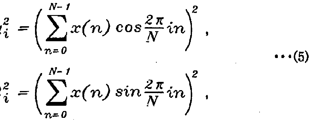
- the surface roughness is measured with a stylus type surface roughness measuring device in accordance with JIS B 0601-2001 (based on ISO4282-1997), and the obtained roughness curve data is used for discrete Fourier transform. Conversion was performed.
- the frequency here is i / (measurement length) for I x (i) I C pointing
- FIG. 2 is a schematic diagram of roughness curve data obtained by measuring the surface roughness of the light diffusion sheet.
- x (n) on the vertical axis represents the distance in the height direction at the nth point obtained by measuring the surface roughness.
- Fig. 3 is a schematic diagram of the graph after discrete Fourier transform of the obtained roughness curve data.
- IX (i) I / N on the vertical axis is “intensity after Fourier transform (IX (i) I) / number of data (N)” (unit: / zm) and represents the size of the unevenness. ing. Therefore, (1) When the value of the number of intensity Z data in the low frequency region is small, it indicates that there is not much unevenness with large pitch, and (2) the value of the number of intensity Z data in the low frequency region When the value is large, it indicates that there are many irregularities with large pitches. (3) When the value of intensity Z data number in the high frequency region is small, there are few irregularities with small pitches. (4) When the value of intensity Z data number is large in the high frequency region Indicates that there are many irregularities with large pitches.
- the light diffusion sheet 11 of the present invention performs discrete Fourier transform on the roughness curve data obtained by measuring the surface roughness of any part of the surface 12 on the viewer side, Since the value divided by the number of data is 0.04 ⁇ m or less in the frequency range of 80 mm_1 or more, the value of the number of intensity Z data is small at least in the high frequency region. Therefore, it shows that there are not many fine irregularities with a small pitch.
- the light diffusing sheet 11 of the present invention having such a surface has an effect that it has glossiness and good contrast.
- the value of the number of intensity Z data is 0.04 m or less in the frequency range of 80 mm_1 or more, and thus is greatly affected by the magnitude of the arithmetic average height Ra of the surface 12 on the viewer side.
- the obtained light diffusing sheet is glossy and has good contrast.
- the present invention may be 0 (zero).
- the arithmetic average height Ra which is one index of the surface roughness, is specified within a predetermined range, and the transmission type screen is used.
- This arithmetic average height Ra literally identifies only the surface unevenness height, and is a parameter that does not consider the period of the unevenness (the reciprocal of the frequency) at all. . Therefore, even if the arithmetic average height Ra is the same value, the appearance of the transmission screen when the observer's power is seen is completely different depending on the period of unevenness. In other words, the period of the unevenness on the surface on the observer side can be summarized as follows.
- a blackish appearance is obtained.
- a light diffusing sheet having irregularities with a small period has a fine-mat-like appearance, loses glossiness, and has a matte appearance.
- the light diffusing member 15 is a constituent member having a light-transmitting transparent or translucent sheet-like member force, and as shown in FIG. BS pattern 17) Force is formed alternately on the bonding surface 19 with the support member 14, and collects substantially parallel light incident from the normal direction of the light diffusing member 15 in the vicinity of the light transmitting portion 16.
- Unit lens for light 18 force is formed on the surface 20 opposite to the bonding surface 19.
- the light diffusing member 15 is a lenticular lens sheet in which the light transmitting portions 16 are partitioned and formed by striped BS patterns 17.
- the unit lens 18 is a so-called lenticular lens that condenses incident light from a light source in the vicinity of the light transmitting portion 16, and is usually a cylindrical extending longitudinally with a convex curved surface on the surface of the incident light. It is a lens.
- the vertically extending unit lenses 18 are arranged in parallel in a direction perpendicular to the longitudinally extending direction Y (for example, the width direction X).
- the light diffusing member 15 is formed of a resin material used for a light-transmitting optical sheet such as a display.
- a resin material for example, a thermoplastic resin can be cited, and a thermoplastic resin that transmits an electron beam such as an electron beam (EB) and an electromagnetic wave such as an ultraviolet ray (UV) is preferable.
- EB electron beam
- UV ultraviolet ray
- acrylic resin, methacrylic resin, and copolymer resin (MS resin) of methacrylic resin and styrene resin are often used.
- the light diffusion member 15 may have a single-layer structure or a two-layer structure.
- the thickness is appropriately set according to the lens pitch, focal length, and desired viewing angle range of the unit lens 18.
- the BS pattern 17 is a stripe-shaped light shielding formed on a flat surface that is a surface of the light diffusing member 15 on the support member 14 side, and formed in a region that does not serve as an optical path of incident light incident from the unit lens 18 side. It is a membrane.
- the BS pattern 17 has an effect of improving the contrast of an image formed on the lenticular lens sheet surface by blocking or absorbing external light from the light exit surface side of the lenticular lens sheet.
- the BS pattern 17 can be formed by various conventionally known methods, and its width and thickness are arbitrarily set.
- the light transmission portion 16 is a portion located between the BS patterns on the surface on which the BS pattern 17 is formed, and is formed in a stripe shape corresponding to each unit lens 18. sand That is, the light transmitting section 16 includes the optical axis of the corresponding unit lens 18, and when the substantially parallel light from the substantially normal direction of the light diffusing member 15 is incident from the unit lens side, the substantially parallel light. It is formed corresponding to the region that becomes the optical path. In terms of appearance, the BS patterns 17 and the light transmission portions 16 are alternately arranged in the horizontal direction.
- the support member 14 and the light diffusing member 15 are bonded together with, for example, an adhesive 33 or the like.
- the light diffusing sheet 11 according to the first embodiment shown in FIG. 1 described above performs discrete Fourier transform on the roughness curve data obtained by measuring the surface roughness of the surface on the viewer side,
- the value force divided by the number of data is 0.04 ⁇ m or less in the frequency range of 80 mm_1 or more, so it has the effect of being glossy and having good contrast.
- FIG. 4 is a schematic cross-sectional view showing a second embodiment of the light diffusion sheet of the present invention.
- the light diffusing sheet 21 according to the second embodiment has a light guide function instead of the light diffusing member 15 constituting the light diffusing sheet 11 according to the first embodiment described above. It is the aspect which provided the light-diffusion member 22 which has.
- the light diffusing member 22 has a substantially V-shaped light absorbing portion 25 composed of a first slope 23 and a second slope 24 bonded to the support member 14. It is formed so as to taper from the surface 19 to the other surface 20 facing it.
- the portion 26 other than the light absorbing portion 25 has a higher refractive index than the light absorbing portion 25, and the first inclined surface 23 and the second inclined surface 24 totally reflect the substantially parallel light incident from the other surface 20.
- a light diffusing member 22 for example, those described in Patent Document 3 (Japanese Patent Application No. 2004-4148) and the like can be applied.
- the light diffusing member 22 is formed so as to have a substantially V-shaped groove by duplication from a mold by a known method such as a heat press method, a thermal polymerization method, a radiation curing method, and the like. It can be formed by filling a gutter-shaped groove with a resin material containing light-absorbing particles by a method such as wiping.
- the material for forming the light diffusing member 22 include the same materials as those of the light diffusing member 15 in the first embodiment described above, and radiation curable resin is particularly preferable.
- the radiation-cured type of resin can be selected from those commonly used in the field, for example For example, an ultraviolet ray curable resin such as an acrylic type, an epoxy type, or a urethane type is preferably used.
- the light diffusing member 22 may have a two-layer structure.
- the light diffusing member 22 is substantially V-shaped on a transparent film or sheet such as a polyester film or a polycarbonate film.
- a groove having a shape can be formed and filled with a resin material containing light-absorbing particles in the groove.
- the substantially V-shaped light absorber 25 is preferably achromatic such as black or gray, but is not limited to this, and a specific wavelength is selectively selected according to the characteristics of the image light.
- Absorbent materials that absorb water may be used.
- the light-absorbing particles contained in the light-absorbing part 25 include carbon salts such as carbon black, graphite, and black iron oxide, colored organic fine particles, colored glass beads, and the like. Examples thereof include xanthene organic dyes such as acid red, and organic acid neodymium such as neodymium carboxylate.
- the light diffusing sheet 21 according to the second embodiment shown in FIG. 4 described above is similar to the light diffusing sheet 11 of the first embodiment, and measures the surface roughness of the surface on the viewer side. Discrete Fourier transform is applied to the obtained roughness curve data, and the value is divided by the number of data. Since the frequency is 80 mm _1 or more and 0.04 m or less, it has gloss and good contrast. It has the effect.
- FIG. 5A is a schematic cross-sectional view showing a third embodiment of the light diffusion sheet of the present invention.
- the light diffusing sheet 31 according to the third embodiment has the transparent layer 32 on the viewer side in the light diffusing sheets 11 and 21 according to the first or second embodiment described above, and the surface of the transparent layer is the surface of the transparent layer.
- the surface roughness discrete Fourier transform for the roughness curve data obtained by measuring, which is 0. 04 m or less and a range of values values force frequency 80 mm _1 or more divided by the data number.
- the measurement of the surface roughness of the transparent layer 32, the discrete Fourier transform, and the like are the same as in the case of the light diffusion sheet of the first or second embodiment.
- FIG. 5 (B) is a modification of that shown in FIG. 5 (A), and the support member 14 includes a light diffusing agent 42.
- the transparent layer 32 is particularly preferably formed by applying a radiation curable resin.
- a radiation curable resin it is possible to select the medium strength of a material that can form a light-transmitting transparent layer that is generally used in this field.
- acrylic, epoxy, An ultraviolet ray curable resin such as a urethane-based resin is preferably used.
- the thickness of the transparent layer 32 is usually preferably 5 to 20 m.
- the transparent layer 32 may be a layer having various functions, for example, an antireflection layer, a hard coat layer, an antistatic layer, an antiglare layer, an antifouling layer, a polarizing filter layer, and An electromagnetic wave shielding layer can be mentioned.
- the light diffusing sheet 31 according to the third embodiment has the surface roughness of the surface 12 of the transparent layer 32 on the observer side. Discrete Fourier transform is performed on the roughness curve data obtained by measurement, and the value divided by the number of data is 0.04 m or less in the frequency range of 80 mm_1 or more, so it has glossiness, Contrast is good, and it has a good effect.
- FIG. 6 is a schematic cross-sectional view showing a fourth embodiment of the light diffusion sheet of the present invention.
- the light diffusing sheet 41 according to the fourth embodiment is characterized in that the light diffusing agent 42 is included in the support member 14 in the light diffusing sheets 11 and 21 according to the first or second embodiment described above. There is.
- the measurement of the surface roughness of the surface 12 on the viewer side, the discrete Fourier transform, and the like are the same as in the light diffusion sheet of the first or second embodiment.
- the light diffusing agent 42 plays a role of controlling the viewing angle in the vertical direction when the light diffusing member 15 controls the viewing angle in the horizontal direction, for example.
- the light diffusing agent 42 may be any light diffusing agent that is generally used in optical sheets.
- styrene resin fine particles silicone resin fine particles, acrylic resin fine particles, MS resin (metatalyl styrene co-polymer).
- Organic fine particles such as polymer fine particles), barium sulfate fine particles, glass fine particles, hydroxyaluminum aluminum fine particles, calcium carbonate fine particles, silica (disilicon dioxide) fine particles, titanium oxide fine particles, glass beads, etc. Examples thereof include inorganic fine particles, and one or more of these can be contained in the resin.
- the difference between the refractive index of the light diffusing agent 42 and the refractive index of the constituent resin of the support member 14 is preferably within 0.1, and more preferably within 0.03.
- the difference in refractive index between the light diffusing agent 42 and the constituent resin of the support member 14 is not impaired.
- the light diffusing agent 42 and the component resin of the support member 14 are selected so as to be within such a range.
- MS resin metatalyl styrene copolymer resin, refractive index: 1.51
- acrylic resin reffractive index: 1.51
- the shape of the light diffusing agent 42 is not particularly limited, but a spherical or substantially spherical shape is usually advantageous in terms of availability.
- the average particle diameter of the light diffusing agent 42 is preferably within the range of 5 to 30 m.
- the light diffusion sheet 41 according to the fourth embodiment is obtained by measuring the surface roughness of the surface 12 on the viewer side, similarly to the light diffusion sheets 11 and 21 of the first or second embodiment. Discrete Fourier transform is applied to the obtained roughness curve data, and the value is divided by the number of data. Since the frequency is 0.04 m or less in the frequency range of 80 mm _1 or more, it has a glossy effect and good contrast. Has fruit.
- FIG. 7 is a schematic cross-sectional view showing a fifth embodiment of the light diffusion sheet of the present invention
- FIG. 8 is a schematic cross-sectional view showing a sixth embodiment of the light diffusion sheet of the present invention.
- the light diffusing sheets 51 and 61 according to the fifth and sixth embodiments are at least the surface 12 on the viewer side in the light diffusing sheets 11 and 21 according to the first or second embodiment described above, and the light diffusing sheets 51 and 61, respectively.
- Light diffuser 42 is included in the vicinity.
- the light diffusing sheet 51 of the fifth embodiment is a mode in which the support member 14 is formed of a single resin layer 62, and the light diffusing sheet 61 of the sixth embodiment has two support members 14. In this embodiment, the resin layer 63, 64 is formed.
- These light diffusion sheets 51 and 61 are not necessarily required to contain the light diffusing agent 42 in at least one of the layer including the surface closest to the viewer and the layer in contact with the layer.
- the light diffusing agent 42 may not be included in all the members 51.
- the light diffusing sheet of these embodiments is preferably formed by including the surface roughness force light diffusing agent 42 of the surface 12 on the viewer side. That is, the surface roughness satisfying the characteristics of the present invention is caused by the light diffusing agent 42 contained in at least one of the layer including the surface on the viewer side and the layer in contact with the layer. Accordingly, fine particles which are the light diffusing agent 42 are present on at least the convex portion of the surface.
- the discrete Fourier transform, etc. This is the same as the light diffusing sheet of the first or second embodiment.
- the light diffusion sheets 51 and 61 according to the fifth and sixth embodiments are similar to the light diffusion sheets 11 and 21 of the first or second embodiment, and the surface roughness of the surface 12 on the viewer side. Discrete Fourier transform is performed on the roughness curve data obtained by measuring the value, and the value divided by the number of data is 0.04 m or less in the frequency range of 80 mm_1 or more, so it has glossiness. It has the effect of good contrast.
- the light diffusion sheet of the present invention described above can be produced by various methods.
- a resin material for forming the support member 14 can be manufactured by a method such as extrusion molding, injection molding, or press molding. At that time, it is manufactured by containing a predetermined amount of a light diffusing agent having a predetermined particle size in the resin material so that the surface roughness of the surface 12 on the observer side has the above-described characteristics of the present invention.
- the surface of the extrusion roll, the surface of the injection mold or the surface of the press mold is formed to have the desired surface roughness according to the present invention to form a shaping mold.
- the material can be manufactured by extrusion, injection molding or press molding.
- the mold roll is subjected to a method such as sandblasting, polishing, or chromium plating.
- the surface roughness of the support member 14 can be controlled.
- the support member 14 thus obtained is bonded to the light diffusion members 15 and 22 and the adhesive 33 which are separately manufactured.
- the adhesive 33 a general adhesive for optical sheet adhesion, such as an ultraviolet curable resin or an adhesive resin, is used.
- FIG. 9 is an explanatory view showing an example of a transmission screen 91 according to the present invention.
- FIG. (B) is an example of a transmissive screen 91 "provided with a total reflection type Fresnel lens sheet 93" having a Fresnel center outside the sheet surface.
- Transmission screen of the present invention 91 (91, 91 ") includes the light diffusion sheet 92 of the present invention and the Fresnel lens sheet 93 (93, 93").
- the light diffusion sheets of the first to sixth embodiments according to the present invention described above can be applied.
- the transmissive screen 91 includes a Fresnel lens sheet 93 on the image light source side of the light diffusion sheet 92.
- the Fresnel lens sheet 93 (93, 93") is projected from the image light source. This is a lens sheet that refracts the projected image light into substantially parallel light to a light diffusion sheet 92 disposed on the viewer side.
- the Fresnel lens sheet 93 (93, 93 ")
- any Fresnel lens sheet having such a function may be used.
- a Fresnel lens sheet preferably provided in the rear projection type display device 101 'shown in FIG. Even if it is a refractive type Fresnel lens sheet 93 ′ (see FIG.
- the Fresnel center preferably provided in the rear projection display device 101 ′′ in FIG. It may be a total reflection Fresnel lens sheet 93 "(see Fig. 9 (B)).
- the total reflection Fresnel lens sheet 93" totally reflects the image light entering the refractive surface. It consists of a Fresnel lens 94 with a total reflection surface. Further, it may be a Fresnel lens sheet having a total reflection Fresnel lens in part.
- the light diffusion sheet 92 As the light diffusion sheet 92, the light diffusion sheets of the first to sixth embodiments described above can be applied, and the parallel light incident from the Fresnel lens sheet 93 is diffused to widen the viewing angle of the image.
- the light diffusion sheet 92 shown in FIGS. 9 (A) and 9 (B) shows an example in which the light diffusion member 22 having the light guide function described in the second embodiment is used as the light diffusion member. From the user side, the support member 14, the adhesive 95, and the light diffusion member 22 are configured in this order.
- the image light from the image light source can be diffused in a predetermined angular range, so that the front force of the transmissive screen 91 is also shifted in the horizontal direction (left-right direction). Even when viewed at a different position, a good image can be observed.
- the transmission type screen 91 of the present invention performs discrete Fourier transform on roughness curve data obtained by measuring the surface roughness of the surface on the viewer side, and a value obtained by dividing the value by the number of data is: With a light diffusion sheet of 0.04 m or less in the frequency range of 80 mm _1 or more, it has the effect of having gloss and good contrast. As a result, a single light source such as LCD or DLP is used as the light source, and it is preferably used as a transmissive screen for rear projection display devices. Therefore, a transmissive screen having gloss and good contrast can be obtained.
- Fig. 10 is a configuration diagram showing an example of a rear projection display device 101 (101 ', 10 1 ") having the transmission screen of the present invention.
- (A) shows the center of the Fresnel in the sheet plane.
- (B) is a transmission with a total reflection type Fresnel lens sheet 93 "having a Fresnel center outside the sheet surface. This is an example using a mold screen 91 ".
- the rear projection display device 101 (101, 101 ′′) includes the transmission screen 91 (91, 91 ′′) of the present invention.
- an image light source 102 is disposed at the bottom of a relatively thin casing 106, and a mirror 105 is disposed in close proximity to the inner surface of the rear wall of the casing 106 and parallel to the vertical direction of the screen.
- the transmission screen 91 is attached to the window portion on the front surface side of the housing 106.
- the image light 103 emitted from the image light source 102 is reflected by the mirror 105 toward the transmissive screen 91, is incident on the transmissive screen 91, is then deflected into substantially parallel light by the Fresnel lens sheet described above, and The light is diffused into the desired diffused light 104 by the light diffusion sheet and emitted from the transmission type screen 91 toward the observer side.
- a light diffusing sheet for a transmissive screen was produced by bonding a support member and a light diffusing member.
- a resin material made of MS (methacryl-styrene) resin was formed by an extrusion molding method.
- This support member was prepared using a molding resin containing about 1 to 2% by weight of a light diffusing agent having a particle size of about 10 to 20 / ⁇ ⁇ made of MS-based resin.
- an antistatic type acrylic resin containing about 10% by weight of a light diffusing agent (particle size: about 10 to 20 m) that also has an acrylic cross-linking particle force is formed on one side of the prepared support member.
- a hard coat layer having a thickness of about 10 m was applied to form a support member having a thickness of 2 mm.
- the surface of the hard coat layer of the support member 14 thus obtained was subjected to discrete Fourier transform on the roughness curve data obtained by measuring the surface roughness, and the value force divided by the number of data. Frequency range of 80 mm_1 or more It was below 0.04 ⁇ m.
- the light diffusing member 15 has a lens pitch of 150 ⁇ m, a lens lateral radius expressed by the lens pitch direction of 80 ⁇ m, and a lens longitudinal radius force expressed by the convex direction of the cylindrical lens of approximately half of 0 ⁇ m.
- a light transmitting portion and a BS pattern were formed in a stripe pattern on the opposite surface of the light diffusing member on the lenticular lens side.
- the light transmitting part had a width of 100 ⁇ m
- the BS pattern had a width of 50 ⁇ m
- the pitch of both was 150 / zm, the same as the lens pitch.
- the produced support member and the light diffusing member were bonded together to produce the light diffusing sheet of Example 1.
- an ultraviolet curable acrylic adhesive is used, and the surface roughness of the support member is adjusted to form the side surface and the BS pattern of the light diffusion member. The other side was pasted together.
- the light diffusing sheet of Example 2 was produced in the same manner as in Example 1 except that the light diffusing member shown below was used.
- the light diffusing member used in Example 2 is a light diffusing member 22 of the type shown in FIG. 4, with a groove pitch of 70 ⁇ m, from the shell occupying surface 19 to the opposite surface 20 of the bonding surface.
- a light diffusion sheet of Example 3 was produced in the same manner as Example 1 except that the support member was produced in the following manner.
- the support member is made of a resin material made of MS (methacryl-styrene) resin by an extrusion molding method. Molded.
- This support member is a molded product in which the total light diffusing agent content is about 1 to 2% by mixing multiple types of light diffusing agents with a particle size of about 10 to 20 m made of MS-based resin. It was prepared using rosin.
- a support member having a thickness of about 2 mm was prepared by coating and curing on the film and bonding this film to the support member. 0 thus obtained surface of the support member 14, the surface roughness discrete Fourier transform for the roughness curve data obtained by measuring, the value in the value obtained by dividing the output frequency 80 mm _1 or more ranges in the data number. 04 ⁇ m or less.
- a light diffusing sheet of Comparative Example 1 was produced in the same manner as Example 1 except that the support member was produced in the following manner.
- a resin material made of MS (methacryl-styrene) resin was formed by an extrusion method.
- This support member is a molded soot having a total light diffusing agent content of about 1 to 2% by mixing a plurality of light diffusing agents having a particle size of about 10 to 20 m made of MS-based resin. It was prepared using fat. Furthermore, an ultraviolet cured film was bonded to one side of the produced support member to produce a support member having a thickness of about 2 mm.
- the film used here was prepared by applying a UV curable resin to a # 320 sandblasted mold and then placing a 100 m thick PET film. Surface of the obtained support member, the surface roughness and the discrete Fourier transform and the roughness curve data obtained by the measurement, the values in the value force frequency 80 mm _1 or more ranges divided by the number of data 0. 04 mu m exceeded.
- a light diffusing sheet of Comparative Example 2 was produced in the same manner as Example 1 except that the support member was produced in the following manner.
- the support member was formed by extrusion molding a resin material made of MS (methacryl-styrene) resin.
- This support member is a molded soot having a total light diffusing agent content of about 1 to 2% by mixing a plurality of light diffusing agents having a particle size of about 10 to 20 m made of MS-based resin. It was prepared using fat. Furthermore, an ultraviolet cured film was bonded to one side of the produced support member to produce a support member having a thickness of about 2 mm.
- the film used here is The # 100 glass bead blasted mold was coated with UV curable resin, and then a 100 ⁇ m thick PET film was placed on it.
- the surface of the obtained support member was subjected to discrete Fourier transform on the roughness curve data obtained by measuring the surface roughness, and the value force divided by the number of data. Frequency in the range of 80 mm _1 or more 0.04 m Exceeded.
- FIG. 11 shows four types of roughness curves (based on JIS B0601-2001, IS04287-1997) of the light diffusion sheets of Examples 1 to 3 and Comparative Examples 1 and 2.
- “Ryanagi” standard surface roughness and shape measuring machine Tokyo Seimitsu Co., Ltd., Surfcom 130A
- measuring speed 0.3 mm Zmin, cut-off 0.25 mm, measuring length 10 mm number of measurement data It was measured at 31207 points (of which 2000 points were used for discrete Fourier transform).
- the arithmetic average height Ra obtained at the same time was also measured and shown in Table 1.
- FIG. 12 shows the result when discrete Fourier transform is performed on the roughness curve data shown in FIG. 11 and the value is divided by the number of data.
- the discrete Fourier transform is the result of calculation using Equation 4 and Equation 5 with 2000 data.
- a transmissive screen combined with a Fresnel lens sheet was configured (see FIG. 9A).
- the Fresnel lens sheet was prepared in a form in which a Fresnel lens made of an epoxy acrylate-based ultraviolet curable resin was formed on a polyester resin film.
- the thus configured transmission type screen was attached to the rear projection type display device having the mode shown in FIG.
- the glossiness was evaluated by visual observation, and a glossiness with a subdued quality was evaluated as ⁇ , and a glossiness was evaluated as X.
- the glossiness was evaluated by measurement based on JIS-Z-8741.
- Gs 60 ° is the intensity ratio of reflected light when the intensity when 60 ° incident light is reflected by the glass surface with a refractive index of 1.567 is 1.
- the intensity ratio of reflected light was measured (%), the result was evaluated. Contrast was evaluated visually, with the blackness level on the appearance suitable for use on television set as ⁇ , and the other one as X.
- the external light reflection was evaluated by visual inspection, and the most appropriate external light reflection when assumed to be used on a television was evaluated as ⁇ , and the appropriate one was evaluated as ⁇ .
- Comprehensive evaluation is a comprehensive evaluation of the transmissive screen equipped with the light diffusing sheet of the present invention as a comprehensive evaluation from the viewpoint of use in television. Those not worthy of evaluation were evaluated as X. The results are shown in Table 1.
- the transmission type screen provided with the light diffusing sheets of Comparative Examples 1 and 2 has almost no power of reflection of external light.
- the surface roughness is the range of the surface roughness of the light diffusing sheets of Examples 1 to 3. Despite being inside, the contrast without gloss was also bad.
- the light diffusion sheets of Comparative Examples 1 and 2 were subjected to discrete Fourier transform on the roughness curve data obtained by measuring the surface roughness, and the value force divided by the number of data. Frequency range of 80 mm _ 1 or more There was a part exceeding 0.04 m.
- the surface of the transmissive screen has a glossy direction. It was excellent.
- the surface of the transmissive screen had a matte feeling like the transmissive screen having the light diffusing sheet of Comparative Examples 1 and 2, the “white-brown” appearance appeared and the contrast was reduced. It was found that these were not significantly affected by the arithmetic average height Ra of the unevenness.
- Roughness curve obtained by measuring the surface roughness of the surface on the viewer side of the obtained transmission screen is subjected to discrete Fourier transform, and the value force obtained by dividing the value by the number of data.
- Frequency 8 OmnT When the range is 1 or more and 0.04 ⁇ m or less, excessive irregular reflection of light with few fine irregularities can be suppressed and glossiness can be improved.
Landscapes
- Physics & Mathematics (AREA)
- General Physics & Mathematics (AREA)
- Optics & Photonics (AREA)
- Chemical & Material Sciences (AREA)
- Dispersion Chemistry (AREA)
- Optical Elements Other Than Lenses (AREA)
- Overhead Projectors And Projection Screens (AREA)
Abstract
Description



Claims
Priority Applications (3)
| Application Number | Priority Date | Filing Date | Title |
|---|---|---|---|
| CNA2005800182579A CN1997918A (zh) | 2004-11-25 | 2005-11-22 | 光扩散片及透射型屏幕 |
| US10/592,415 US20070201131A1 (en) | 2004-11-25 | 2005-11-22 | Diffusing Sheet And Rear Projection Screen |
| KR1020067021389A KR100882992B1 (ko) | 2004-11-25 | 2005-11-22 | 광 확산 시트 및 투과형 스크린 |
Applications Claiming Priority (2)
| Application Number | Priority Date | Filing Date | Title |
|---|---|---|---|
| JP2004340463A JP4676190B2 (ja) | 2004-11-25 | 2004-11-25 | 光拡散シート及び透過型スクリーン |
| JP2004-340463 | 2004-11-25 |
Publications (1)
| Publication Number | Publication Date |
|---|---|
| WO2006057243A1 true WO2006057243A1 (ja) | 2006-06-01 |
Family
ID=36497980
Family Applications (1)
| Application Number | Title | Priority Date | Filing Date |
|---|---|---|---|
| PCT/JP2005/021447 Ceased WO2006057243A1 (ja) | 2004-11-25 | 2005-11-22 | 光拡散シート及び透過型スクリーン |
Country Status (6)
| Country | Link |
|---|---|
| US (1) | US20070201131A1 (ja) |
| JP (1) | JP4676190B2 (ja) |
| KR (1) | KR100882992B1 (ja) |
| CN (1) | CN1997918A (ja) |
| TW (1) | TW200632382A (ja) |
| WO (1) | WO2006057243A1 (ja) |
Cited By (3)
| Publication number | Priority date | Publication date | Assignee | Title |
|---|---|---|---|---|
| WO2009028769A1 (en) * | 2007-08-28 | 2009-03-05 | Cheil Industries Inc. | Light diffusion film having good uniformity of surface roughness and method for manufacturing the same |
| US8062730B2 (en) | 2007-12-05 | 2011-11-22 | Cheil Industries, Inc. | Light diffusion film with uniform surface roughness and low retardation value, display including the same, and associated methods |
| JP2015004979A (ja) * | 2014-07-30 | 2015-01-08 | 富士フイルム株式会社 | 偏光板、画像表示装置、及び防眩フィルムの製造方法 |
Families Citing this family (12)
| Publication number | Priority date | Publication date | Assignee | Title |
|---|---|---|---|---|
| JP2008032846A (ja) * | 2006-07-26 | 2008-02-14 | Dainippon Printing Co Ltd | 光学シート、透過型スクリーンおよび背面投射型表示装置 |
| CN101408628A (zh) * | 2007-10-10 | 2009-04-15 | 群康科技(深圳)有限公司 | 扩散片及其制造工艺、背光模组及液晶显示装置 |
| US8000006B2 (en) * | 2009-07-02 | 2011-08-16 | Morgan Adhesives Company | Rear-projection screen |
| JP5837495B2 (ja) * | 2009-08-25 | 2015-12-24 | スリーエム イノベイティブ プロパティズ カンパニー | 光方向転換フィルム及びそれを組み込んだディスプレイシステム |
| PL2626216T3 (pl) * | 2011-03-10 | 2018-12-31 | Hueck Rheinische Gmbh | Sposób obróbki powierzchni narzędzia do wytłaczania mającej strukturę oraz narzędzie do wytłaczania |
| JP6102194B2 (ja) * | 2012-11-09 | 2017-03-29 | 船井電機株式会社 | プロジェクタおよび投影用スクリーン |
| KR102109473B1 (ko) * | 2012-11-21 | 2020-05-12 | 쓰리엠 이노베이티브 프로퍼티즈 컴파니 | 광학 확산 필름 및 이를 제조하는 방법 |
| CN105068162A (zh) * | 2015-08-11 | 2015-11-18 | 华南理工大学 | 一种具有电磁屏蔽功能的扩散增亮膜及其制备方法 |
| US10563309B1 (en) | 2015-10-13 | 2020-02-18 | Kings Mountain International, Inc. | Method for creating a textured press plate |
| JP7090842B2 (ja) * | 2017-07-27 | 2022-06-27 | 日本電気硝子株式会社 | 波長変換部材及び発光装置 |
| KR102449562B1 (ko) * | 2017-11-27 | 2022-10-07 | 현대모비스 주식회사 | 자동차 내장부품용 투광성 부재 |
| CN116339061A (zh) * | 2023-03-07 | 2023-06-27 | 凯鑫森(上海)功能性薄膜产业股份有限公司 | 一种大视角投影膜及其制备方法 |
Citations (6)
| Publication number | Priority date | Publication date | Assignee | Title |
|---|---|---|---|---|
| JPS6337205A (ja) * | 1986-07-31 | 1988-02-17 | Tokyo Seimitsu Co Ltd | 表面粗さ測定方法 |
| WO1997028403A1 (en) * | 1996-02-01 | 1997-08-07 | Mitsubishi Rayon Co., Ltd. | Surface light source element and liquid crystal display device, sign device and traffic control sign device using same |
| JP2001075299A (ja) * | 1999-09-03 | 2001-03-23 | Ricoh Co Ltd | 有機感光体及びその製造方法 |
| US6331371B1 (en) * | 1998-08-19 | 2001-12-18 | Nec Corporation | Electrophotographic photoreceptor and its manufacturing method |
| US20020167725A1 (en) * | 2001-05-14 | 2002-11-14 | Masahiro Goto | Sheet for use for projection screen, light diffusion sheet and projection screen |
| JP3507082B2 (ja) * | 1997-01-20 | 2004-03-15 | 大日本印刷株式会社 | 透過型スクリーン |
Family Cites Families (13)
| Publication number | Priority date | Publication date | Assignee | Title |
|---|---|---|---|---|
| US4504888A (en) * | 1983-03-23 | 1985-03-12 | Pennywise Enterprises, Inc. | Photographer's diffuser light |
| JP3381570B2 (ja) * | 1997-09-22 | 2003-03-04 | 凸版印刷株式会社 | プロジェクションスクリーン用レンチキュラーシート |
| US6466368B1 (en) * | 2000-04-26 | 2002-10-15 | 3M Innovative Properties Company | Rear projection screen with reduced speckle |
| US6535333B1 (en) * | 2000-11-21 | 2003-03-18 | 3M Innovative Properties Company | Optical system with reduced color shift |
| JP2002196117A (ja) * | 2000-12-25 | 2002-07-10 | Nitto Denko Corp | 光拡散層、光拡散性シート及び光学素子 |
| ATE301299T1 (de) * | 2001-01-11 | 2005-08-15 | Arisawa Seisakusho Kk | Rückseiten-übertragungsschirm |
| JP3918439B2 (ja) * | 2001-02-09 | 2007-05-23 | 凸版印刷株式会社 | 透過型スクリーン |
| JP3818125B2 (ja) * | 2001-10-30 | 2006-09-06 | 凸版印刷株式会社 | 透過型スクリーン |
| JP2006126222A (ja) * | 2002-02-04 | 2006-05-18 | Kuraray Co Ltd | 透過型スクリーン |
| US6846098B2 (en) * | 2002-05-16 | 2005-01-25 | Eastman Kodak Company | Light diffuser with variable diffusion |
| KR100631421B1 (ko) * | 2002-11-22 | 2006-10-16 | 아오디스(주) | 투과형 및 반사형 영상 스크린과 그의 제조방법 |
| JP2004286996A (ja) * | 2003-03-20 | 2004-10-14 | Dainippon Printing Co Ltd | 透過型スクリーン |
| US7453639B2 (en) * | 2003-03-25 | 2008-11-18 | Dai Nippon Printing Co., Ltd. | Diffusion sheet, rear projection screen provided with diffusion sheet, method of manufacturing mold for diffusion sheet, and method of manufacturing diffusion sheet |
-
2004
- 2004-11-25 JP JP2004340463A patent/JP4676190B2/ja not_active Expired - Fee Related
-
2005
- 2005-11-22 CN CNA2005800182579A patent/CN1997918A/zh active Pending
- 2005-11-22 KR KR1020067021389A patent/KR100882992B1/ko not_active Expired - Fee Related
- 2005-11-22 US US10/592,415 patent/US20070201131A1/en not_active Abandoned
- 2005-11-22 WO PCT/JP2005/021447 patent/WO2006057243A1/ja not_active Ceased
- 2005-11-24 TW TW094141308A patent/TW200632382A/zh unknown
Patent Citations (6)
| Publication number | Priority date | Publication date | Assignee | Title |
|---|---|---|---|---|
| JPS6337205A (ja) * | 1986-07-31 | 1988-02-17 | Tokyo Seimitsu Co Ltd | 表面粗さ測定方法 |
| WO1997028403A1 (en) * | 1996-02-01 | 1997-08-07 | Mitsubishi Rayon Co., Ltd. | Surface light source element and liquid crystal display device, sign device and traffic control sign device using same |
| JP3507082B2 (ja) * | 1997-01-20 | 2004-03-15 | 大日本印刷株式会社 | 透過型スクリーン |
| US6331371B1 (en) * | 1998-08-19 | 2001-12-18 | Nec Corporation | Electrophotographic photoreceptor and its manufacturing method |
| JP2001075299A (ja) * | 1999-09-03 | 2001-03-23 | Ricoh Co Ltd | 有機感光体及びその製造方法 |
| US20020167725A1 (en) * | 2001-05-14 | 2002-11-14 | Masahiro Goto | Sheet for use for projection screen, light diffusion sheet and projection screen |
Cited By (3)
| Publication number | Priority date | Publication date | Assignee | Title |
|---|---|---|---|---|
| WO2009028769A1 (en) * | 2007-08-28 | 2009-03-05 | Cheil Industries Inc. | Light diffusion film having good uniformity of surface roughness and method for manufacturing the same |
| US8062730B2 (en) | 2007-12-05 | 2011-11-22 | Cheil Industries, Inc. | Light diffusion film with uniform surface roughness and low retardation value, display including the same, and associated methods |
| JP2015004979A (ja) * | 2014-07-30 | 2015-01-08 | 富士フイルム株式会社 | 偏光板、画像表示装置、及び防眩フィルムの製造方法 |
Also Published As
| Publication number | Publication date |
|---|---|
| US20070201131A1 (en) | 2007-08-30 |
| CN1997918A (zh) | 2007-07-11 |
| JP4676190B2 (ja) | 2011-04-27 |
| JP2006153949A (ja) | 2006-06-15 |
| TW200632382A (en) | 2006-09-16 |
| KR100882992B1 (ko) | 2009-02-12 |
| KR20070038031A (ko) | 2007-04-09 |
Similar Documents
| Publication | Publication Date | Title |
|---|---|---|
| JP5630076B2 (ja) | 反射スクリーン、映像表示システム、反射スクリーンの製造方法 | |
| JPH0855507A (ja) | 面光源、それを用いた表示装置、及びそれらに用いる光拡散シート | |
| JP4044931B2 (ja) | フレネルレンズシート、透過型スクリーン及び背面透過型表示装置 | |
| JP4676190B2 (ja) | 光拡散シート及び透過型スクリーン | |
| JP2005241920A (ja) | 光拡散性スクリーン | |
| JP2006065266A (ja) | 反射スクリーン、反射投影システム、及び、反射スクリーンの製造方法 | |
| KR100446223B1 (ko) | 투과형스크린 | |
| JP2012252112A (ja) | 反射スクリーンおよびその製造方法 | |
| JP5250933B2 (ja) | 反射スクリーン、及び、反射スクリーンの製造方法 | |
| JP2013195914A (ja) | 反射スクリーン、映像表示装置 | |
| JP2006267778A (ja) | 光拡散シート及び透過型スクリーン | |
| JP5747661B2 (ja) | 反射スクリーン及び画像表示装置 | |
| JP2006227279A (ja) | 光拡散シート及び透過型スクリーン | |
| JP2004206037A (ja) | フレネルレンズシート、透過型スクリーンおよび背面投射型表示装置 | |
| JPH11102024A (ja) | 透過型スクリーン | |
| JP2008032956A (ja) | 光拡散シート、透過型スクリーン及び背面投射型表示装置 | |
| JP2014115343A (ja) | 透過型スクリーン、背面投射型表示装置 | |
| JPH10260638A (ja) | レンチキュラースクリーン及びその製造方法 | |
| JP3965407B2 (ja) | フレネルレンズシート及び透過型スクリーン | |
| JP2004272235A (ja) | フレネルレンズシート及び背面投射型スクリーン | |
| JP2006065185A (ja) | 透過型スクリーン及びその製造方法並びに背面投射型表示装置 | |
| JP2006030715A (ja) | 透過型スクリーン | |
| JP2008046205A (ja) | 反射シート、反射スクリーン | |
| JP6398517B2 (ja) | 反射型スクリーン、映像表示システム | |
| JP2007133209A (ja) | 表面保護シートおよび透過型スクリーン |
Legal Events
| Date | Code | Title | Description |
|---|---|---|---|
| AK | Designated states |
Kind code of ref document: A1 Designated state(s): AE AG AL AM AT AU AZ BA BB BG BR BW BY BZ CA CH CN CO CR CU CZ DE DK DM DZ EC EE EG ES FI GB GD GE GH GM HR HU ID IL IN IS JP KE KG KM KN KP KR KZ LC LK LR LS LT LU LV LY MA MD MG MK MN MW MX MZ NA NG NI NO NZ OM PG PH PL PT RO RU SC SD SE SG SK SL SM SY TJ TM TN TR TT TZ UA UG US UZ VC VN YU ZA ZM ZW |
|
| AL | Designated countries for regional patents |
Kind code of ref document: A1 Designated state(s): BW GH GM KE LS MW MZ NA SD SL SZ TZ UG ZM ZW AM AZ BY KG KZ MD RU TJ TM AT BE BG CH CY CZ DE DK EE ES FI FR GB GR HU IE IS IT LT LU LV MC NL PL PT RO SE SI SK TR BF BJ CF CG CI CM GA GN GQ GW ML MR NE SN TD TG |
|
| 121 | Ep: the epo has been informed by wipo that ep was designated in this application | ||
| WWE | Wipo information: entry into national phase |
Ref document number: 10592415 Country of ref document: US Ref document number: 2007201131 Country of ref document: US |
|
| WWE | Wipo information: entry into national phase |
Ref document number: 1020067021389 Country of ref document: KR |
|
| WWE | Wipo information: entry into national phase |
Ref document number: 200580018257.9 Country of ref document: CN |
|
| WWP | Wipo information: published in national office |
Ref document number: 1020067021389 Country of ref document: KR |
|
| NENP | Non-entry into the national phase |
Ref country code: DE |
|
| WWP | Wipo information: published in national office |
Ref document number: 10592415 Country of ref document: US |
|
| 122 | Ep: pct application non-entry in european phase |
Ref document number: 05809389 Country of ref document: EP Kind code of ref document: A1 |
|
| NENP | Non-entry into the national phase |
Ref country code: JP |