WO1996012208A1 - Affichage a cristaux liquides - Google Patents
Affichage a cristaux liquides Download PDFInfo
- Publication number
- WO1996012208A1 WO1996012208A1 PCT/JP1995/002123 JP9502123W WO9612208A1 WO 1996012208 A1 WO1996012208 A1 WO 1996012208A1 JP 9502123 W JP9502123 W JP 9502123W WO 9612208 A1 WO9612208 A1 WO 9612208A1
- Authority
- WO
- WIPO (PCT)
- Prior art keywords
- light
- liquid crystal
- crystal panel
- display device
- crystal display
- Prior art date
Links
Classifications
-
- G—PHYSICS
- G02—OPTICS
- G02F—OPTICAL DEVICES OR ARRANGEMENTS FOR THE CONTROL OF LIGHT BY MODIFICATION OF THE OPTICAL PROPERTIES OF THE MEDIA OF THE ELEMENTS INVOLVED THEREIN; NON-LINEAR OPTICS; FREQUENCY-CHANGING OF LIGHT; OPTICAL LOGIC ELEMENTS; OPTICAL ANALOGUE/DIGITAL CONVERTERS
- G02F1/00—Devices or arrangements for the control of the intensity, colour, phase, polarisation or direction of light arriving from an independent light source, e.g. switching, gating or modulating; Non-linear optics
- G02F1/01—Devices or arrangements for the control of the intensity, colour, phase, polarisation or direction of light arriving from an independent light source, e.g. switching, gating or modulating; Non-linear optics for the control of the intensity, phase, polarisation or colour
- G02F1/13—Devices or arrangements for the control of the intensity, colour, phase, polarisation or direction of light arriving from an independent light source, e.g. switching, gating or modulating; Non-linear optics for the control of the intensity, phase, polarisation or colour based on liquid crystals, e.g. single liquid crystal display cells
- G02F1/133—Constructional arrangements; Operation of liquid crystal cells; Circuit arrangements
- G02F1/1333—Constructional arrangements; Manufacturing methods
- G02F1/1335—Structural association of cells with optical devices, e.g. polarisers or reflectors
- G02F1/1336—Illuminating devices
- G02F1/133621—Illuminating devices providing coloured light
-
- G—PHYSICS
- G02—OPTICS
- G02F—OPTICAL DEVICES OR ARRANGEMENTS FOR THE CONTROL OF LIGHT BY MODIFICATION OF THE OPTICAL PROPERTIES OF THE MEDIA OF THE ELEMENTS INVOLVED THEREIN; NON-LINEAR OPTICS; FREQUENCY-CHANGING OF LIGHT; OPTICAL LOGIC ELEMENTS; OPTICAL ANALOGUE/DIGITAL CONVERTERS
- G02F1/00—Devices or arrangements for the control of the intensity, colour, phase, polarisation or direction of light arriving from an independent light source, e.g. switching, gating or modulating; Non-linear optics
- G02F1/01—Devices or arrangements for the control of the intensity, colour, phase, polarisation or direction of light arriving from an independent light source, e.g. switching, gating or modulating; Non-linear optics for the control of the intensity, phase, polarisation or colour
- G02F1/13—Devices or arrangements for the control of the intensity, colour, phase, polarisation or direction of light arriving from an independent light source, e.g. switching, gating or modulating; Non-linear optics for the control of the intensity, phase, polarisation or colour based on liquid crystals, e.g. single liquid crystal display cells
- G02F1/133—Constructional arrangements; Operation of liquid crystal cells; Circuit arrangements
- G02F1/1333—Constructional arrangements; Manufacturing methods
- G02F1/1335—Structural association of cells with optical devices, e.g. polarisers or reflectors
- G02F1/1336—Illuminating devices
- G02F1/133602—Direct backlight
- G02F1/133605—Direct backlight including specially adapted reflectors
-
- G—PHYSICS
- G03—PHOTOGRAPHY; CINEMATOGRAPHY; ANALOGOUS TECHNIQUES USING WAVES OTHER THAN OPTICAL WAVES; ELECTROGRAPHY; HOLOGRAPHY
- G03B—APPARATUS OR ARRANGEMENTS FOR TAKING PHOTOGRAPHS OR FOR PROJECTING OR VIEWING THEM; APPARATUS OR ARRANGEMENTS EMPLOYING ANALOGOUS TECHNIQUES USING WAVES OTHER THAN OPTICAL WAVES; ACCESSORIES THEREFOR
- G03B21/00—Projectors or projection-type viewers; Accessories therefor
- G03B21/005—Projectors using an electronic spatial light modulator but not peculiar thereto
- G03B21/006—Projectors using an electronic spatial light modulator but not peculiar thereto using LCD's
-
- G—PHYSICS
- G03—PHOTOGRAPHY; CINEMATOGRAPHY; ANALOGOUS TECHNIQUES USING WAVES OTHER THAN OPTICAL WAVES; ELECTROGRAPHY; HOLOGRAPHY
- G03B—APPARATUS OR ARRANGEMENTS FOR TAKING PHOTOGRAPHS OR FOR PROJECTING OR VIEWING THEM; APPARATUS OR ARRANGEMENTS EMPLOYING ANALOGOUS TECHNIQUES USING WAVES OTHER THAN OPTICAL WAVES; ACCESSORIES THEREFOR
- G03B21/00—Projectors or projection-type viewers; Accessories therefor
- G03B21/14—Details
- G03B21/20—Lamp housings
- G03B21/208—Homogenising, shaping of the illumination light
-
- H—ELECTRICITY
- H04—ELECTRIC COMMUNICATION TECHNIQUE
- H04N—PICTORIAL COMMUNICATION, e.g. TELEVISION
- H04N9/00—Details of colour television systems
- H04N9/12—Picture reproducers
- H04N9/31—Projection devices for colour picture display, e.g. using electronic spatial light modulators [ESLM]
- H04N9/3141—Constructional details thereof
- H04N9/315—Modulator illumination systems
-
- G—PHYSICS
- G02—OPTICS
- G02F—OPTICAL DEVICES OR ARRANGEMENTS FOR THE CONTROL OF LIGHT BY MODIFICATION OF THE OPTICAL PROPERTIES OF THE MEDIA OF THE ELEMENTS INVOLVED THEREIN; NON-LINEAR OPTICS; FREQUENCY-CHANGING OF LIGHT; OPTICAL LOGIC ELEMENTS; OPTICAL ANALOGUE/DIGITAL CONVERTERS
- G02F1/00—Devices or arrangements for the control of the intensity, colour, phase, polarisation or direction of light arriving from an independent light source, e.g. switching, gating or modulating; Non-linear optics
- G02F1/01—Devices or arrangements for the control of the intensity, colour, phase, polarisation or direction of light arriving from an independent light source, e.g. switching, gating or modulating; Non-linear optics for the control of the intensity, phase, polarisation or colour
- G02F1/13—Devices or arrangements for the control of the intensity, colour, phase, polarisation or direction of light arriving from an independent light source, e.g. switching, gating or modulating; Non-linear optics for the control of the intensity, phase, polarisation or colour based on liquid crystals, e.g. single liquid crystal display cells
- G02F1/133—Constructional arrangements; Operation of liquid crystal cells; Circuit arrangements
- G02F1/1333—Constructional arrangements; Manufacturing methods
- G02F1/1335—Structural association of cells with optical devices, e.g. polarisers or reflectors
- G02F1/133526—Lenses, e.g. microlenses or Fresnel lenses
-
- G—PHYSICS
- G02—OPTICS
- G02F—OPTICAL DEVICES OR ARRANGEMENTS FOR THE CONTROL OF LIGHT BY MODIFICATION OF THE OPTICAL PROPERTIES OF THE MEDIA OF THE ELEMENTS INVOLVED THEREIN; NON-LINEAR OPTICS; FREQUENCY-CHANGING OF LIGHT; OPTICAL LOGIC ELEMENTS; OPTICAL ANALOGUE/DIGITAL CONVERTERS
- G02F1/00—Devices or arrangements for the control of the intensity, colour, phase, polarisation or direction of light arriving from an independent light source, e.g. switching, gating or modulating; Non-linear optics
- G02F1/01—Devices or arrangements for the control of the intensity, colour, phase, polarisation or direction of light arriving from an independent light source, e.g. switching, gating or modulating; Non-linear optics for the control of the intensity, phase, polarisation or colour
- G02F1/13—Devices or arrangements for the control of the intensity, colour, phase, polarisation or direction of light arriving from an independent light source, e.g. switching, gating or modulating; Non-linear optics for the control of the intensity, phase, polarisation or colour based on liquid crystals, e.g. single liquid crystal display cells
- G02F1/133—Constructional arrangements; Operation of liquid crystal cells; Circuit arrangements
- G02F1/1333—Constructional arrangements; Manufacturing methods
- G02F1/1335—Structural association of cells with optical devices, e.g. polarisers or reflectors
- G02F1/1336—Illuminating devices
- G02F1/133602—Direct backlight
- G02F1/133606—Direct backlight including a specially adapted diffusing, scattering or light controlling members
- G02F1/133607—Direct backlight including a specially adapted diffusing, scattering or light controlling members the light controlling member including light directing or refracting elements, e.g. prisms or lenses
-
- G—PHYSICS
- G02—OPTICS
- G02F—OPTICAL DEVICES OR ARRANGEMENTS FOR THE CONTROL OF LIGHT BY MODIFICATION OF THE OPTICAL PROPERTIES OF THE MEDIA OF THE ELEMENTS INVOLVED THEREIN; NON-LINEAR OPTICS; FREQUENCY-CHANGING OF LIGHT; OPTICAL LOGIC ELEMENTS; OPTICAL ANALOGUE/DIGITAL CONVERTERS
- G02F1/00—Devices or arrangements for the control of the intensity, colour, phase, polarisation or direction of light arriving from an independent light source, e.g. switching, gating or modulating; Non-linear optics
- G02F1/01—Devices or arrangements for the control of the intensity, colour, phase, polarisation or direction of light arriving from an independent light source, e.g. switching, gating or modulating; Non-linear optics for the control of the intensity, phase, polarisation or colour
- G02F1/13—Devices or arrangements for the control of the intensity, colour, phase, polarisation or direction of light arriving from an independent light source, e.g. switching, gating or modulating; Non-linear optics for the control of the intensity, phase, polarisation or colour based on liquid crystals, e.g. single liquid crystal display cells
- G02F1/133—Constructional arrangements; Operation of liquid crystal cells; Circuit arrangements
- G02F1/1333—Constructional arrangements; Manufacturing methods
- G02F1/1335—Structural association of cells with optical devices, e.g. polarisers or reflectors
- G02F1/1336—Illuminating devices
- G02F1/133621—Illuminating devices providing coloured light
- G02F1/133623—Inclined coloured light beams
-
- G—PHYSICS
- G02—OPTICS
- G02F—OPTICAL DEVICES OR ARRANGEMENTS FOR THE CONTROL OF LIGHT BY MODIFICATION OF THE OPTICAL PROPERTIES OF THE MEDIA OF THE ELEMENTS INVOLVED THEREIN; NON-LINEAR OPTICS; FREQUENCY-CHANGING OF LIGHT; OPTICAL LOGIC ELEMENTS; OPTICAL ANALOGUE/DIGITAL CONVERTERS
- G02F1/00—Devices or arrangements for the control of the intensity, colour, phase, polarisation or direction of light arriving from an independent light source, e.g. switching, gating or modulating; Non-linear optics
- G02F1/01—Devices or arrangements for the control of the intensity, colour, phase, polarisation or direction of light arriving from an independent light source, e.g. switching, gating or modulating; Non-linear optics for the control of the intensity, phase, polarisation or colour
- G02F1/13—Devices or arrangements for the control of the intensity, colour, phase, polarisation or direction of light arriving from an independent light source, e.g. switching, gating or modulating; Non-linear optics for the control of the intensity, phase, polarisation or colour based on liquid crystals, e.g. single liquid crystal display cells
- G02F1/133—Constructional arrangements; Operation of liquid crystal cells; Circuit arrangements
- G02F1/1333—Constructional arrangements; Manufacturing methods
- G02F1/1335—Structural association of cells with optical devices, e.g. polarisers or reflectors
- G02F1/1336—Illuminating devices
- G02F1/133626—Illuminating devices providing two modes of illumination, e.g. day-night
- G02F1/133627—Projection-direct viewing
-
- G—PHYSICS
- G02—OPTICS
- G02F—OPTICAL DEVICES OR ARRANGEMENTS FOR THE CONTROL OF LIGHT BY MODIFICATION OF THE OPTICAL PROPERTIES OF THE MEDIA OF THE ELEMENTS INVOLVED THEREIN; NON-LINEAR OPTICS; FREQUENCY-CHANGING OF LIGHT; OPTICAL LOGIC ELEMENTS; OPTICAL ANALOGUE/DIGITAL CONVERTERS
- G02F1/00—Devices or arrangements for the control of the intensity, colour, phase, polarisation or direction of light arriving from an independent light source, e.g. switching, gating or modulating; Non-linear optics
- G02F1/01—Devices or arrangements for the control of the intensity, colour, phase, polarisation or direction of light arriving from an independent light source, e.g. switching, gating or modulating; Non-linear optics for the control of the intensity, phase, polarisation or colour
- G02F1/13—Devices or arrangements for the control of the intensity, colour, phase, polarisation or direction of light arriving from an independent light source, e.g. switching, gating or modulating; Non-linear optics for the control of the intensity, phase, polarisation or colour based on liquid crystals, e.g. single liquid crystal display cells
- G02F1/133—Constructional arrangements; Operation of liquid crystal cells; Circuit arrangements
- G02F1/1333—Constructional arrangements; Manufacturing methods
- G02F1/1335—Structural association of cells with optical devices, e.g. polarisers or reflectors
- G02F1/1336—Illuminating devices
- G02F1/133628—Illuminating devices with cooling means
Definitions
- the present invention relates to a liquid crystal display device having excellent light use efficiency and image quality.
- the present invention is mainly disclosed with respect to a projection type liquid crystal display device, but can also be used for a direct view type and a fiber type. Background art
- the divergence angle of light passing through the liquid crystal panel must be about 0.15 rad pp in the first direction (narrow directional direction). It is necessary to limit the range to 0.3 rad pp (about twice the above 0.15) in the second direction (wide directivity direction).
- Fig. 1 shows a conventional projection type liquid crystal display.
- 1 is a light source
- 2 is a parabolic mirror
- 3 is a liquid crystal panel
- 4 is a projection lens
- 5 is a screen.
- Arrows indicate the paths of light rays.
- the parabolic mirror 2 has a rotationally symmetric shape with its optical axis as the axis. is there. Therefore, the cross section of the output light is circular, and if the radius is 1, the area is.
- the liquid crystal panel 3 is rectangular or square, and the area of the rectangle inscribed in the unit circle is 2 or less. Therefore, in the peripheral area, a loss of about 36% (1-2 / ⁇ ) occurs due to the mismatch of the antenna.
- Figure 2 shows the coordinate system. Take ⁇ in the direction of the optical axis of the parabolic mirror 2, and let r be the distance from the optical axis.
- the shape of the parabolic mirror 2 is given by the following equation.
- the light source is assumed to be isotropic, and its intensity is I [cd]. Therefore, its total luminous flux is 4 ⁇ I [lm].
- the increment of the luminous flux from the isotropic light source is proportional to the solid angle increment. According to spherical geometry, the solid angle increase is proportional to the cosine increment of the zero zenith angle measured from the optical axis through the light source.
- the total luminous flux T collimated by the parabolic mirror 2 and the light utilization E (0M) are obtained, the following equations are obtained.
- the shape of the liquid crystal panel is assumed to be a disk shape, and the above-mentioned (3) above-mentioned loss of aspect mismatch is neglected.
- the illuminance J of the parallel light output from the parabolic mirror 2 is inversely proportional to the square of the distance from the light source to the mirror. Therefore, J
- the conventional technology has a problem that when the light utilization rate is improved, the peripheral light quantity ratio is deteriorated.
- the quality of the reproduced image that is, the contrast ratio
- the contrast ratio is almost inversely proportional to the square of the divergence angle of the incident light and deteriorates. Therefore, the above proposal degrades the contrast ratio by about 36 times. Therefore, the above proposal has not yet been put to practical use.
- JP-A-6-250-177 of the present inventor proposes that a lenticular lens is arranged on each of the incident side and the exit side of the liquid crystal panel. It could not help solve the problem of contrast ratio degradation.
- Another object of the present invention is to provide a light source device for a projection type liquid crystal display with improved heat dissipation efficiency.
- Another object of the present invention is to provide a projection-type liquid crystal display with reduced resolution degradation and reduced moire disturbance.
- Another object of the present invention is to provide a projection type liquid crystal display with reduced ghost disturbance.
- Another object of the present invention is to provide a liquid crystal display of a direct-view type, an optical fiber type or a projection type which has an excellent light utilization rate by applying the above-mentioned improved liquid crystal display technology.
- Another object of the present invention is to provide a liquid crystal display device having a pixel arrangement more matched to the visual psychology based on the resolution of the human eye.
- Another object of the present invention is to provide a large-sized liquid crystal display device that is resistant to changes in ambient temperature, gravity, and the like.
- the first, second and third light refracting means and the first light reflecting means are provided.
- Part of the output light from the light source is input to the first light refraction means, and the output light is supplied to the inner peripheral part of the liquid crystal panel means via the second light refraction means, A part of the output light from the light source is input to the first light reflecting means, and the output light is supplied to the outer peripheral part of the liquid crystal panel means through the third light refracting means,
- the third light refracting means is formed such that the light deflection angle at the outermost periphery is algebraically smaller than the deflection angle at the innermost periphery,
- the light deflection angles at the innermost periphery of the third light refracting means are the first and second light refracting means. Smaller than the sum of the respective light deflection angles of the outermost peripheral portion of the third light refracting means, and the direction of the outgoing light of the innermost peripheral portion of the third light refracting means and the outermost peripheral portion of the second light refracting means. It is formed so that the direction of the emitted light substantially matches.
- the western hemisphere in a polar coordinate system having a light source as an origin, is provided with spherical light reflecting means, and the eastern hemisphere is provided with light traveling direction changing means (collimator means). At least, it comprises a first direction light deflecting means and a second direction light deflecting means.
- a spherical light reflecting means is provided in the western hemisphere, and an air flow opening means is provided in a high latitude area at the north and south ends of the spherical light reflecting means.
- the transmission path of the collimator output light is provided with a shaping means.
- three primary colors, three directions, and three positions are arranged on the light incident side of the liquid crystal panel means along the traveling direction of the light (first lenticular lens means). And a light divergence angle reducing means (second lenticular lens means).
- the light divergence direction of the three primary color and three direction making means matches the wide directivity direction of the liquid crystal panel means.
- a polarization direction matching unit is provided.
- a light diverging means for diverging light at least in the horizontal direction is arranged between the liquid crystal panel and the projection lens.
- a Fresnel ghost obstacle reducing means is provided between a liquid crystal panel means and a screen means.
- a three-primary-color and three-direction means using a diffraction grating is shown.
- a three-primary-color five-direction means using a diffraction grating and a prism array is shown.
- a liquid crystal panel means using a pre-annealed thin glass plate is shown.
- the configuration of each of the above-described means acts to improve the relative illuminance of the outer peripheral portion of the liquid crystal panel means.
- the combination of the light refracting means and the light reflecting means achieves an improvement in light utilization.
- the spherical light reflecting means acts to cause the light emitted from the light source to the western hemisphere to return to the light source and re-emit to the eastern hemisphere.
- the first direction light deflecting means acts to deflect the light in the latitude decreasing direction.
- the second direction light deflecting means acts to deflect the light in the longitude spread reduction direction.
- the air flow opening means provided at the north-south end of the spherical light reflecting means in the western hemisphere corresponds to a position where the light source means can be seen straight. Therefore, air can be efficiently circulated and the heat dissipation efficiency can be improved.
- the orienting means is formed by arranging a large number of black thin plates in a cabinet along a traveling direction of light. It acts to absorb light with poor parallelism that is incident at a large angle, and reflects light with good parallelism that is incident at a relatively small angle. Therefore, the parallelism of light can be improved and the divergence angle of light can be reduced. Therefore, the contrast ratio can be improved.
- the light divergence angle reducing means has an action of reducing the divergence angle of the three primary color lights to about half. Therefore, the divergence angle of 6 times in the conventional proposal can be reduced to 3 times. Further, the direction of the triple divergence angle can be matched with the wide directivity direction of the liquid crystal panel means by the polarization direction matching means. By halving the divergence angle, the contrast ratio is improved to about 4 times. The harmonization of the polarization direction, as compared with the case of 4 5 degrees misalignment, thereby improving the contrast ratio of about 2-fold (sec 2 4 5 °).
- the light utilization rate is improved by three times, but the contrast ratio is severely impaired, whereas in the present invention, the light utilization rate (luminance) is reduced without deterioration of contrast. It can be improved by a factor of three.
- the merit index of display quality is proportional to the product of luminance and contrast ratio. Therefore, the impact of this project is great.
- the horizontal spot size can be increased by the light diverging means. Therefore, it is possible to reduce moiré interference caused by interference between the vertical stripe structure of the screen and the pixel arrangement structure of the liquid crystal panel without light loss.
- the Fresnel ghost obstacle reducing means has an action of aligning the direction of the plane of polarization of projection light (the plane including the direction of vibration of the electric field and the direction of light propagation) in the vertical direction.
- the light having a plane of polarization in the vertical direction acts as a P-wave at the upper and lower ends of the Fresnel lens forming the screen.
- the upper and lower ends of the Fresnel lens have the property that the reflectance for P-waves is extremely small. Therefore, ghost disturbance due to reflection of the reciprocating light in the Fresnel plate is reduced.
- the three-primary-color three-directional means using the diffraction grating transmits the positive diffraction first-order light output by the diffraction grating toward the liquid crystal panel means, and outputs the negative first-order diffraction light output by the diffraction grating.
- the light is reflected by a mirror, and the reflected output acts so as to become parallel light in the direction of the above-mentioned diffraction primary light of positive polarity. Therefore, the emitted light of both positive and negative polarities can be used. Therefore, light use efficiency can be improved.
- the three-primary-color five-direction conversion means separates the input parallel white light into the five directions of RGBGR.c.
- the light in the five directions converges to each position of five arrangement positions of three primary color pixels (RGBGR) by a lenticular lens. Is done. Therefore, light use efficiency can be improved. Further, the pixel arrangement is compatible with the visual psychology regarding the resolution of the human eye.
- the pre-annealed thin glass plate acts to apply a uniform pressure to the liquid crystal layer of the liquid crystal panel means. Therefore, it is possible to configure a liquid crystal display device with less unevenness in image quality depending on environmental changes.
- FIG. 1 is a diagram schematically showing a conventional liquid crystal display device.
- FIG. 2 is a graph for explaining the performance of the conventional liquid crystal display device:
- FIG. 3 is a graph for explaining the performance of the conventional liquid crystal display device c .
- FIG. 4 is a graph for explaining the performance of the conventional liquid crystal display device c
- FIG. 5 is a graph for explaining the performance of the conventional liquid crystal display device c
- Figure 6 is a graph illustrating the performance of the display apparatus, was the basis of the present invention, a coordinate system for explaining a generalized light flux storage principle shown.
- FIG. 7 is a graph for explaining a thinking process leading to the present invention.
- FIG. 8 is a graph for explaining a thinking process leading to the present invention.
- FIG. 9 is a graph for explaining the thinking process leading to the present invention.
- FIG. 10 is a graph for explaining the thinking process leading to the present invention.
- FIG. 11 is a graph for explaining the thinking process leading to the present invention.
- FIG. 12 is a schematic configuration diagram for explaining a first embodiment of the present invention.
- FIG. 13 is a schematic configuration diagram for explaining a modification of the first embodiment.
- FIG. 14 is a schematic configuration diagram for explaining a method of designing a Fresnel lens.
- FIG. 15 is a diagram showing an aspect ratio of a liquid crystal panel.
- FIG. 16 is a diagram showing a modification of the light source.
- FIG. 17 is a view showing a modification of the first embodiment.
- FIG. 18 is a diagram showing a modification of the first embodiment of the present invention.
- FIG. 19A and FIG. 19B show a modified example of the first embodiment, and are a schematic configuration diagram and a plan view showing light reflecting means, respectively.
- FIG. 20 is a diagram showing a modification of the first embodiment.
- FIG. 21 is a schematic configuration diagram for explaining a second embodiment of the present invention.
- FIG. 22 is an enlarged configuration diagram of a main part of FIG. 21.
- FIG. 23 is a diagram showing a schematic optical configuration in the prior art.
- FIGS. 24A, 24B and 24C are diagrams each showing a modification of the second embodiment.
- FIGS. 25A and 25B are views showing a modification of the second embodiment.
- 26A and 26B are a schematic optical configuration diagram and a main portion optical configuration diagram showing another embodiment of the present invention.
- FIG. 27 is a schematic optical configuration diagram showing another embodiment of the present invention.
- FIG. 28 is a schematic optical configuration diagram showing a modification of FIG.
- FIG. 29 is a diagram showing an application of the present invention to a fiber type liquid crystal display.
- FIG. 30 is a perspective view showing an application example of the present invention to a direct-view liquid crystal display.
- FIG. 31 is a diagram showing a modification of FIG. 30.
- FIG. 32 is a diagram showing a modification of FIG. 31.
- FIG. 33 is a perspective view showing an example of a transmission screen.
- FIG. 34 is a schematic optical configuration diagram of a transmission type display device to which the present invention is applied. .
- FIG. 35 is a perspective view for explaining the principle of FIG. 34.
- FIG. 36 is a graph for explaining the principle of FIG.
- FIG. 37 is a schematic optical configuration diagram showing a means for solving the problem of the first embodiment.
- FIG. 38 is a front view of the rear projection display apparatus of the present invention.
- FIG. 39 is a horizontal plan view of the Fresnel sheet.
- FIG. 40 is a diagram for explaining ghost disturbance.
- FIG. 41 is a graph for explaining the reflectance in the device of the present invention.
- FIG. 42 is a perspective view showing a schematic optical configuration for explaining a part of the embodiment of the present invention.
- FIG. 43 is a schematic optical configuration diagram showing a modification of the three-primary-color, three-direction turning means in the second embodiment of the present invention.
- FIG. 44 is a schematic optical configuration diagram for explaining details of a main part of FIG. 43.
- FIG. 45 is a graph showing the applicable range of the embodiment shown in FIG.
- FIG. 46 is a schematic optical configuration diagram showing another modified example of the present invention.
- FIG. 47 is a detailed optical configuration diagram of the three primary colors and five directions means, which is the main part of FIG.
- FIG. 48 is a diagram showing a schematic optical cross-sectional configuration of a liquid crystal panel.
- FIG. 49 is a view for explaining the basic principle of the liquid crystal panel forming method of the present invention.
- FIG. 50 is a graph showing a pre-annealing profile.
- FIG. 51 is a schematic horizontal cross section showing a material of a double-sided lenticular lens.
- FIG. 52 is a schematic optical configuration diagram showing a modification of the three-primary-color three-direction turning means of the present invention.
- FIG. 53 is a schematic optical configuration diagram showing a modification of the three primary color, three-direction forming means of the present invention.
- FIG. 54 is a schematic optical configuration diagram showing a fundamental basic configuration of a collimator of the present invention in which an effect mismatch loss is reduced.
- FIGS. 55A and 55B are schematic optical configuration diagrams showing one specific embodiment of FIG. 54, and are a vertical sectional view and a horizontal sectional view, respectively.
- FIG. 56 is a schematic sectional view showing an optical configuration of an aspect ratio reducing means.
- FIGS. 57A and 57B are schematic optical cross-sectional views showing another modification of the embodiment of FIG. 54.
- FIG. 58 is a schematic optical cross-sectional view showing another modification of the embodiment of FIG. 54.o- FIG. 59A and FIG. 59B show heat dissipation of a light source in the present invention.
- FIG. 3 is a schematic longitudinal sectional view and a transverse sectional view for supporting means.
- FIGS. 6OA and 60B are a longitudinal sectional view and a transverse sectional view, respectively, for explaining another embodiment of the heat dissipation means of the light source in the embodiment of the present invention.
- FIG. 61 is a schematic sectional view showing a partially modified example in FIG. 60.
- FIG. 62 is a schematic optical configuration diagram of another embodiment of the present invention.
- FIG. 63 is a graph for explaining the principle of the rectifier in the embodiment of the present invention.
- FIG. 64 is a schematic cross-sectional view showing a means for improving the contrast ratio of the panel emission part.
- C FIG. 65 is a schematic optical configuration diagram showing a moiré interference reduction means.
- FIG. 66 is an optical path diagram for explaining the principle of FIG. 65.
- FIG. 67 is a graph for explaining the principle of FIG.
- FIG. 68 is a graph for explaining the principle of FIG.
- FIG. 69 is a graph for explaining the principle of FIG.
- FIG. 70 is a graph for explaining the principle of FIG.
- FIG. 71 is a schematic sectional view showing a basic configuration of the geometric distortion correcting means.
- FIGS. 72A, 72B and 72C are optical path diagrams for explaining the optical principle of FIG. 71.
- FIG. 73 is a schematic sectional view showing a specific example of the geometric distortion correcting means in FIG. 71.
- FIG. 74 is a schematic cross-sectional view showing a modification of the three-primary-color three-direction forming means applicable to the present invention. as well as
- FIG. 75 is a schematic cross-sectional view showing a modified example of the three-primary-color three-direction forming means of FIG. BEST MODE FOR CARRYING OUT THE INVENTION
- Equation (9) the amount of luminous flux passing through any one cross-sectional area S> on the light traveling path is given by the right-hand side of Equation (9), and its value is calculated by the following equation. Is the corresponding value in one cross-section S 2 , ie equal to equation (9 ′).
- This equation enables Helmholtz-Lagrange's law, which is valid only on the image plane of the aberration-free optical system, to be applied to any interface in the middle of a more general, lossless light propagation path having an arbitrary aberration. It has been extended by the inventor.
- ni and n 2 are the refractive indices of the medium to which the cross-sectional areas S, and S 2 belong, respectively.
- dx and dy are the derivatives of the local orthonormal coordinates (x, y) on the cross section on the optical path. Is the latitude component in the X direction in the light direction 0 measured from the normal direction of the cross section element, and 0 y is the latitude component in the y direction.
- 1 is a light source
- 1 ' is a cross-section element
- 1'"' is a direction of light.
- the surface of the light emitting part of the light source has a spherical shape with a radius of 3 mm, is a Lambertian, and has a surface luminance of 100 million nits, the total luminous flux is 100 million nits-4 ⁇ (3 mm 2 )? Rsr, that is, about 355001m.
- FIG. 7 shows the light source 1 and the disk surface 7.
- the light collimating means is not shown.
- the distance between light source 1 and disk surface 7 is L, the central illuminance E of the disk surface without light collimating means. Is given by
- the radius of the disk is twice the distance L between the light source and the disk. This can be insighted from the fact that the surface area of a sphere of radius L is equal to the surface area of a disk of radius 2 L.
- S the total area of uniform Lambertian light source luminance, total luminous flux is TT S is, by the optical system of any lossless, which led to the light receiving surface of the area S 2, force, one, when uniformly the illuminance, the area of the two-dimensional divergence angle sine of the light receiving surface S, it is the formula (9) is equal to Bruno S 2 ratio power can et deduced.
- the illuminance on the disk can be made uniform. That is, the peripheral light amount ratio can be made 100%.
- the magnitude of the microscopic light divergence angle at the position of the radius R on the disk is determined.
- the divergence angle is different between the radial direction, ie, the meridional direction, and the circumferential direction, ie, the sagittal direction. Therefore, let each be em ( ⁇ , ⁇ s ( ⁇ ).
- the illuminance on the spherical surface is equal to the above described ⁇ 0 everywhere in the case of the isotropic light source.
- the circumference of the ring on the spherical surface sharing the zenith angle 0 and the width is equal to 2; z "Lsin 0, and the width is equal to the drum 0.
- the disk 7 corresponding to the ring on the spherical surface The ring on top of which has a circumference of 27: R or 4 ⁇ Lsin 0.5 ⁇
- Equation 1 The width is A 2 Lsin 0.50, that is, L cos 0.
- Equation (14) implies that the divergence angle is small because the length is enlarged on the circle ⁇ ⁇ in the sagittal direction, that is, the circumferential direction, and the divergence angle is small on the disk in the regional direction, that is, the radial direction.
- the divergence angle becomes large because its length force ⁇ is reduced.
- curve 8 shows the sagittal divergence angle
- curve 9 shows the divergence angle.
- FIG. 9 shows the above divergence angle on the front view of the disk 7.
- the major axis of the ellipse showing the divergence angle is equal to £ m ( ⁇ )
- the minor axis is equal to £ S ( ⁇ ).
- the area of the center circle is equal to the area of the surrounding ellipse
- the surrounding illuminance is equal to the center illuminance.
- the divergence angles ⁇ (0) and ⁇ s (0) at the periphery of the disk are each equal to ⁇ (0) cos 2 0.50. That was proportional to the divergence angle area cos 4 0. 50. This explains the problem of the prior art shown in FIG. 4 from another aspect.
- the square of this ratio is lZcos 4 0.56, the improvement ratio of the peripheral light ratio. It has become. In order to maximize the practical effect of the present invention, it is desirable that the improvement ratio be about 1.4 times or more. To achieve this, the angle of divergence of the incident light at the diagonal corner of the liquid crystal panel incident surface (meaning the incident surface before passing through the lenticular lens, which will be described later) should be about 1.2 times or more the sagittal divergence angle. It is recommended that It is considered that the meaning of the divergence angle was understood from the above explanation.
- reference numerals 114 and 115 are auxiliary lines for design.
- 1 14 corresponds to a portion with a zenith angle of about 60 degrees or less
- 1 15 corresponds to a portion with a zenith angle of about 60 degrees or more.
- the length of the radial radius P is set as shown in the figure, according to the following equation.
- FIG. 10 After light emitted from light source 1 in the 0 direction crosses the auxiliary lines 1 1 4 and 1 15, As shown in FIG. 10, if the light is converted in a direction parallel to the optical axis 110, the incident illuminance on the disk 7 becomes uniform. The reason is based on the principle already described in FIG. However, it is extremely difficult to realize the function represented by FIG. 10 by one optical means. Therefore, FIG. 10 is converted into FIG. In FIG. 11, reference numeral 116 denotes an auxiliary line, which is obtained by inverting the portion of the zenith angle of about 60 degrees or more in FIG.
- the function represented by the auxiliary line 114 in FIG. 11 is realized by the first light refraction means and the second light refraction means, and the function represented by the auxiliary line 116 is realized by the first line. It is considered to be realized by the light reflecting means of the above and the third light refracting means. This is shown in Figure 12.
- 1 13 is a first light refracting means
- 10 is a second light refracting means
- 10 ′ is a third light refracting means
- 1 17 is a first light reflecting means.
- the first, second and third light refracting means can be specifically constituted by a light refracting lens or a Fresnel lens.
- a Fresnel lens when the known incident angle is ⁇ and the outgoing angle is 7 based on the above-described drawing, the prism angle ⁇ may be selected as in the following equation. The meaning of each symbol is as shown in FIG.
- n is the refractive index of Fresnel medium S
- n is the refractive index of the medium c
- the first light reflecting means indicated by 117 can be specifically realized by a concave mirror.
- FIG. 12 except for a dotted line portion and auxiliary lines 114 and 116 is a main part of the first embodiment of the present invention.
- the light deflection angle of the light refracting means is the angle between the direction of light incident on the light refracting means and the direction of light emitted from the light refracting means.
- First, second and third light refraction means and first light reflection means are provided at least in the path from the light source means to the liquid crystal panel means,
- a part of the output light from the light source means is input to the first light refraction means, and the output light is directed to the inner peripheral part of the liquid crystal panel means via the second light refraction means.
- a part of the output light from the light source means is input to the first light reflection means, and the output light passes through the third light refraction means, and is provided on the outer periphery of the liquid crystal panel means. Supplied in the direction
- the third light refracting means is formed such that the light deflection angle at the outermost periphery is algebraically smaller than the deflection angle at the innermost periphery,
- the light deflection angle at the innermost periphery of the third light refraction means is smaller than the sum of the respective light deflections at the outermost periphery of the first and second light refraction means, And a liquid crystal formed such that the direction of the outgoing light at the innermost periphery of the third light refracting means and the direction of the outgoing light at the outermost periphery of the second light refracting means substantially match.
- Display device As can be understood from the above description, the projection lens 4 and the screen 5 in FIG. 1 are not essential requirements of the first embodiment. Also, as shown in FIG. 12, the second and third light refracting means may be formed integrally.
- the cutting boundary between the auxiliary lines 114 and 116 is described as a zenith angle of about 60 degrees, but this angle can be selected to be any acute angle.
- the shape of the first light reflecting means is generally spherical, but may be replaced by a spherical mirror. As described above, it is recommended that the magnitude of the regional divergence angle of the incident light at the diagonal corner of the liquid crystal panel be about 1.2 times or more the sagittal divergence angle.
- FIG. A first modification example in which FIG. 12 differs from FIG. 12 is that a supporting stem 111 is added to the light source 1.
- a second modification is to add a second light reflecting means 118.
- the second light reflecting means improves the light use efficiency by reflecting the input light from the light source 1 and reflecting the output light back to the light source 1.
- a metal halide lamp, a xenon lamp, or a magnetron excitation lamp is specifically used as the light source 1, it is desirable that the output reflected light be slightly decentered so as to return toward the outer periphery of the light source 1. This is because in the seed light source family, blue light tends to be absorbed when the light passes through the plasma inside the light source.
- a third modification is the addition of the light shielding means 1 19.
- the light shield means 119 is arranged on the outer periphery of the first light refraction means 113 so as to be along the light emission direction from the light source.
- the purpose and effect of the light shielding means is to prevent the output light from the first light reflection means 117 from being erroneously input to the first light refraction means. As a result, an abnormal increase in the light divergence angle can be prevented, and therefore, the contrast ratio of the reproduced image can be improved, and thus the image quality can be improved.
- a fourth modification is the addition of the third light reflecting means 120.
- the means is disposed in a region where the effective surface of the liquid crystal panel 3 does not exist in the light traveling direction at the rear thereof, and contributes to an improvement in light utilization.
- the output reflected light 122 of the means is returned to the light source 1.
- FIG. 15 shows a front view of the light source side as viewed from the liquid crystal panel means.
- 120 is a third light reflecting means, that is, a shaded portion.
- Reference numeral 122 denotes a light transmitting portion, the inner peripheral portion of which corresponds to the second light refracting device, and the outer peripheral portion of which corresponds to the third light refracting device.
- the third light reflecting means may be arranged between the third light refracting means and the first light reflecting means.
- Fig. 13 it is important to seal the gap between the means 10 ', 1 17, 1 18 and 1 1 1 to prevent the ingress of debris when using it in a dusty environment.
- a refrigerant having a small refractive index such as silicone oil.
- the light source 1 be a well-known double tube type.
- the light refraction means is a visible light refraction.
- the means it is desirable to reflect non-visible light such as infrared light or ultraviolet light.
- non-visible light such as infrared light or ultraviolet light.
- the light reflecting means means visible light reflecting means, and desirably transmits non-visible light such as infrared light or ultraviolet light.
- Such desirable properties can be imparted by applying well-known multilayer technology. This holds true for most of the following explanations.
- FIG. 16 shows a modification of the light source means 1.
- ⁇ 11 is a spherical light source provided with stems on both sides, and ⁇ 'is a light source having a light emitting portion long in the optical axis direction.
- ⁇ ' is a light source having a light emitting portion long in the optical axis direction.
- FIG. 17 shows a modification of the light source arrangement. In the figure, each number is as described above. 1 2
- Reference numeral 3 denotes a rectangular tube light guide tube. Adjusting the direction of the light sources 11 and 11 'to the direction of the short side of the screen, that is, the vertical direction of the screen in general, is effective in improving the light utilization rate. In this case, the portion indicated by 1 17 ′ of the first light reflecting means in FIG. 17 can be deleted.
- FIG. 18 c a modified example of FIG. 13 showing a modified example of the first embodiment of the present invention is shown in FIG. 18 c .
- FIG. 18 is different from FIG.
- the second light refraction means are realized by one refraction lens indicated by 1 1 3 ′.
- the entrance side interface 113 of the refraction lens forms first light refraction means
- the exit side interface 110 forms second light refraction means.
- the second difference is that the third light reflecting means indicated by 120 'is moved to the light incident side of the first light reflecting means.
- the third light reflecting means is arranged in an area where there is no effective light transmitted to the subsequent liquid crystal panel means.
- the light reflecting means reflects light emitted from the light source toward the light source or toward the outer periphery of the light source. Therefore, light use efficiency can be improved.
- 10 ′ and 1 13 ′ may be integrally formed structurally.
- FIG. 18 Still another modification is shown in FIG. This figure is different from FIG. 18 in that the outer periphery of the third light refracting means indicated by 10 ′ has a negative focusing power, that is, a negative light deflection angle. That is, it is configured to have.
- FIG. 19B shows a front view based on the Mercator projection when the shape of the third light reflecting means 120 ′ in the configuration of FIG. 19A is viewed from the direction of the light source means 1.
- the petal-shaped annular portion 120 'of four valves is the third light reflecting means.
- the dotted line 1 1 1 ′ in the petals of the four valves is the stem of the light source means 1.
- This stem is omitted in the cross-sectional view drawn at the top of FIG. FIG. 20 shows another modification of the first embodiment.
- the first, second and third light refracting means in FIG. 19A are formed by a structurally integrated Fresnel lens. The meaning of each number in the figure is as described above.
- the light deflection angle at the innermost part of the third light refracting means 10 ′ and the sum of the light deflection angles at the outermost parts of the first and second light refracting means 11 13 and 10 are discontinuous. Note that it has changed to This property is one of the characteristics common to the first embodiment and its modifications.
- the illuminance on the outer peripheral part of the second light refracting means tends to be insufficient. is there.
- the illuminance reduction rate is practically acceptable.
- the decrease in the illuminance can be compensated by controlling the direction of the light emitted from the second light reflecting means 118.
- a portion of 120 ° indicated by a dotted line near the third light refracting means 120 ′ corresponds to the short side direction on the reproduced image, that is, usually the up-down direction. This means that the third light reflecting means is extended.
- the material of the integrally formed Fresnel lens can be such that the light incident side is made of a glass material and the light emitting side is made of a synthetic resin. It is also recommended to form an invisible light reflection film on the incident surface of the Fresnel lens. This is because doing so can extend the life of the synthetic resin on the emission side.
- FIG. 20 an example of the actual dimensions when using a liquid crystal panel means of 10 inches diagonally and an aspect ratio of 4: 3 is as follows.
- the diameter of the second light refracting means is about 160 mm, and the maximum diameter of the third light refracting means is about 250 mm.
- the length of the short side of the liquid crystal panel is about 150 mm, which is smaller than the diameter of the second light refracting means.
- the effective portions of the first to third light refraction means and the first light reflection means have been described on the assumption that they have rotationally symmetric shapes with respect to the optical axis. However, these may generally be rotationally asymmetrical shapes. By doing so, the output luminous flux can be approximated not to a circular shape but to a shape close to a rectangle (122 in Fig. 15).
- supplementary measures for the problems in the first embodiment will be added.
- an annular ring is formed at the boundary between the second and third light refraction means 10 ′. Shade occurs.
- the first embodiment described above basically belongs to an optical system that is rotationally symmetric with respect to the optical axis (meaning rotational symmetry except for the outer peripheral portion of the output light). Equation (9) discovered by the present inventors is also effective for constructing a rotationally asymmetric collimator optical system. Such modifications will be described later with reference to FIG.
- FIG. 21 shows a second embodiment of the present invention.
- the figure is a horizontal sectional view.
- 3, 4, and 5 are the same as those already described.
- Reference numeral 12 denotes a block in which the light source means and the light traveling direction changing means are combined, and the above-described first embodiment of the present invention can be used.
- 13, 14, and 15 are three primary color three-way means. Specifically, dichroic mirrors for reflecting each of the RGB primary colors are used. Instead of the dichroic mirrors, a diffraction grating filter means described in JP-A-5-2571114 of the present inventor may be used.
- the 45-degree oblique direction refers to the direction of the long-axis arrangement of molecules on the incident side of the liquid crystal layer of the nematic liquid crystal type liquid crystal panel means (3).
- 16 ' is a half-wave plate for rotating the plane of polarization by 45 degrees.
- the polarization plane can be rotated 45 degrees by using the half-wave plate with the optical axis (optical anisotropy axis) inclined at 22.5 degrees.
- the exit side polarizing sheet is usually adhered to the exit surface of the liquid crystal panel (3) to be integrally formed.
- the illustration is omitted in FIG.
- Reference numeral 17 denotes a double-sided lenticular lens, which is provided with a three-way three-positioning means (first lenticular lens means) 18 on the incident side and a light divergence angle reducing means (second lenticular lens means) on the exit side. 9 is provided.
- Reference numeral 20 denotes a pixel of the liquid crystal panel means (3). The operation of 17, 18 and 19 will be explained with reference to FIGS. 22 and 23. Both figures are enlarged views for one cycle. In FIG. 22, 3, 17, 18, 18, 19, and 20 are as described above.
- Reference numerals 20 'and 20 "respectively denote a human-lit surface and a light-emitting surface of the liquid crystal panel means 3.
- the focal length of the light divergence angle reducing means (19) ( ⁇ ,) is selected to be almost equal to the distance ( ⁇ ,) in Fig. 22 between the three-way three-positioning means (18) and 19.
- the entrance surface of the liquid crystal panel means (3) The distance ( ⁇ 2 ) between 20 ′) and the pixel plane (20) is chosen to be smaller than ⁇ , and in practice smaller than 2 times 3 times ⁇ , so that the emitted light
- the divergence angle of (light passing through the liquid crystal panel pixel surface) is about 3 ⁇ as shown in the figure.
- the value of T to be 60% to 120% of the value of f
- one important object of the present invention is as follows. Ratio improvement) can be achieved. This is because by doing so, the increase in the divergence angle of the R and B lights compared to the G light can be reduced by 60% or more.
- the focal length f of the three-way three-positioning means 18. Is selected to satisfy equation (1 9 ").
- the essential constituent element in the present embodiment of the present invention is to satisfy Expressions (19 ') and (19 ⁇ ) and Expression (20). ⁇
- Fig. 23 shows the case where this is removed.
- the direction of RGB of light passing through the pixel surface of the liquid crystal panel lacks unification, and its divergence angle is as large as about 6 ⁇ .
- the divergence angle (3 ⁇ ) in the present invention is improved by about 1 ⁇ 2 times as compared with the divergence angle (6 ⁇ ) in the prior art.
- the contrast ratio of the reproduced image is inversely proportional to the square of the light divergence angle when passing through the pixel surface of the liquid crystal panel. Therefore, according to the present invention, the contrast ratio can be improved to about 4 times.
- the diverging direction of the light matches the wide directional angle direction of the liquid crystal panel means, the effect of improving the contrast ratio is large.
- Fig. 21 only four periods of the lenticular lens are shown for the sake of clarity, but in reality, several hundred periods or more are formed on one panel. The same applies to the following figures.
- the half-wave plate (16 ′) may be omitted depending on the application. In that case, the color purity or contrast ratio is slightly degraded.
- Figures 24, 24, and 24C show modifications of the light divergence angle reducing means (19).
- No. Figure 24A shows a trapezoidal columnar lenticular lens.
- FIG. 24B shows concave sides of each side of the trapezoid in FIG. 24A.
- FIG. 24C is a diagram in which each side of the trapezoid in FIG. 24A is formed into a convex lens. That is, as shown in the figure, the divergence of R, G, and B light is reduced while preventing the divergence of the R, B light in the left-right direction.
- Fig. 24 is effective when the divergence angle ⁇ (0) force of the incident light is sufficiently smaller than that described above. It is not effective when ⁇ (0) is almost equal to ⁇ . This concludes the description of Figures 24, 24, and 24C.
- FIGS. 25A and 25B show further modifications. 21 to 24 are horizontal sectional views, while FIG. 25 is a vertical sectional view.
- a lenticular lens means 1 '' that converges light in the vertical direction (narrow directional angle of the liquid crystal panel) is added to improve light utilization. This is the configuration.
- the requirement of this configuration is that the focal length of the lens means 17 ′ is larger than the focal length of the lens means 18. By doing so, light utilization can be improved while minimizing deterioration of the contrast ratio.
- FIG. 25B shows a modification for applying the present invention to a polarized glasses type stereoscopic display.
- reference numeral 200 denotes the exit-side polarizing plate described above
- reference numerals 100 and 100 denote horizontal stripe-shaped half-wave plates for rotating the polarization plane by 90 degrees.
- the polarization plane can be rotated 90 ° by using the half-wave plate with the optically anisotropic optical axis inclined at 45 °.
- 1001, 1002, 1003, and 1004 are emission lights corresponding to the first, second, third, and fourth scanning lines, respectively. As can be seen from the figure, only the even-numbered outgoing light has its polarization plane rotated 90 °.
- the left-eye signal is applied to the pixels corresponding to the odd-numbered scanning lines
- the right-eye signal is applied to the pixels corresponding to the even-numbered scanning lines.
- a polarizing plate that passes only the light corresponding to the polarizing plate 20 "is added for the left eye
- Practical horizontal stripe-shaped half-wave plate (100000, 100000', ......) can be formed by a molecular alignment direction alignment method using a light distribution film, which is well known in liquid crystal panel manufacturing technology.
- FIG. 6A shows a third embodiment of the present invention.
- the feature of this example is that Fresnel lens means 11 is arranged on the emission side of the liquid crystal panel means (3). Since the emitted light can be converged in the direction of the projection lens means (4) by the Fresnel lens means (11), there is an advantage that the diameter of the projection lens means (4) can be reduced.
- the projection lens means (4) is shown as a single lens element for simplicity of illustration, but it is actually composed of a plurality of lens elements.
- the shape of the aperture of the projection lens means (4) is recommended to be formed in an ellipse or ellipse having a major axis in the wide directivity direction of the liquid crystal panel means (3). Is done. This is because by doing so, unnecessary extraneous light can be prevented from passing, and therefore the contrast ratio (image quality) of the reproduced image can be improved.
- FIG. 26B shows a modification of the Fresnel lens means (11).
- 170 is the first Fresnel sheet
- 171 is the second Fresnel sheet
- 172 is the Fresnel lens surface formed on the exit side of the first Fresnel sheet
- 173 is the second Fresnel sheet
- 174 is a discontinuous part of the first Fresnel sheet
- 175 is a discontinuous part of the second Fresnel sheet
- 176 is both sheets Adhesive part for bonding at the periphery.
- the angle of view can be increased to about 30 degrees or more, and thus a compact optical system having a short projection distance can be configured.
- FIG. 27 shows a fourth embodiment of the present invention for improving light use efficiency.
- the inside of the dotted line in the figure is the main part of this embodiment, which is the light utilization improving means, and is a configuration for using both P and S waves. Since the inside of the dotted line is symmetrical, only the right half is described.
- 21 is a polarizing beam splitter that passes a P wave and reflects an S wave.
- 22 is a half-wave plate for rotating the plane of polarization by 90 degrees, and converts a P wave into an S wave.
- 23 is a reflector. In this figure, the form using the S wave is shown, but a form using the P wave may be used instead.
- FIG. 28 shows a partially modified example of FIG. 2 1 ′ is a polarizing beam splitter, 2 2 ′ is a half-wave plate for rotating the polarization plane by 90 degrees, and 2 3 ′ is a reflecting mirror.
- FIG. 29 shows an application example of the present invention to an optical fiber type liquid crystal display. Parts such as the light traveling direction changing means are not shown in the figure. In the figure, 17 and 3 are as described above.
- Reference numeral 24 denotes an optical fiber group
- reference numeral 25 denotes an optical fiber input end
- FIG. 30 shows an application example of the present invention to a direct-view liquid crystal display.
- reference numeral 26 denotes lenticular lens means for diverging light in the vertical direction.
- FIG. 31 shows a direct-view liquid crystal display in which FIG. 30 is rotated 90 degrees.
- the wide-angle direction of the directional characteristics of the liquid crystal panel means (3, 3 ') is the horizontal direction in FIG. 30 and the vertical direction in FIG.
- FIG. 32 is an enlarged horizontal sectional view of the embodiment of FIG.
- 26 ' is a lenticular lens means for diverging light in the horizontal direction
- 35 is a lenticular lens
- 36 is a black stripe (black printing portion).
- this configuration in order to prevent the occurrence of moire pattern damage caused by the interference between the pixel (20) structure of the liquid crystal panel means (3 ') and the lenticular lens (35) structure, it is also shown in FIG. It is necessary to satisfy the conditional expression.
- the quotient obtained by dividing the product of the distance (T 3 ) between the pixel plane and the focal plane of the lenticular lens and the divergence angle ( ⁇ ) of the incident light by the refractive index ( ⁇ ) of the medium is the array pitch of the lenticular lens. Must be greater than 0.75 times ⁇ . Where the quotient is equal to the pitch, the moiré disturbance is very small. Regarding the moiré interference in Fig. 30 It is the same as above.
- the configuration shown in FIG. 31 has an advantage over the configuration shown in FIG. 30 in that the deterioration of the contrast ratio due to external ambient light 12 on the image display surface of the liquid crystal display can be reduced. This is the end of the description of FIGS. 30 and 31.
- Fig. 33 shows an example of the structure of a transmission type screen.
- reference numeral 27 denotes a lenticular lens for converging and diverging light in the vertical direction, the pitch of which is approximately 0.1 mm or less
- 28 denotes a Fresnel lens surface whose pitch is approximately 0.1
- 29 denotes the horizontal direction.
- a lenticular lens for converging and diverging light at a pitch of about 0.5 images, and 30 is a black stripe surface.
- the lenticular lens 29 interferes with the vertical striped pixel structure of the liquid crystal panel, causing moire interference.
- Fig. 34 shows a side view of a cabinet-type projection liquid crystal display.
- 12, 3, 4, and 5 are as described above.
- Reference numerals 31, 32 and 33 are light reflection means.
- the moire interference is reduced by reducing the light reflecting means 32 in FIG. 34 to a vertical or horizontal cylindrical shape. Therefore, it is not necessary to use a large amount of diffusing material, and the image quality can be improved.
- Figure 35 shows the principle of moiré interference reduction.
- 32 is a cylindrical light reflecting means
- 34 is a cross section of a light beam.
- the solid arrows are the upper and lower rays of the light beam, and the dotted arrows are the left and right rays of the light beam.
- the horizontal spot size has the width A as shown. Select this width A to be about 1.22 times the pitch T of the lenticular lens 29. Thereby, the moiré interference can be significantly reduced. In practice, the effect can be sufficiently obtained by selecting the horizontal defocus width A to be at least 0.8 times the pitch T of the lenticular lens 29.
- Figure 36 shows the calculated values of the moiré interference reduction effect of the cylindrical mirror when the projection lens aberration is assumed to be zero.
- FIG. 38 shows a front view when the present invention is applied to a rear projection display.
- 5 is a screen
- 177 is a cabinet
- 178, 178 ' is a speaker arrangement part
- 179, 179' are shelves for storing optical disk players, VTRs, optical disks, tapes, etc. It is an arrangement part.
- This example is recommended for use with the example shown in FIGS. This is because if the embodiment shown in FIGS. 26 and 34 is applied, the depth of the cabinet can be made compact.
- FIG. 33 A horizontal cross-sectional view of the Fresnel sheet in the transmission type screen illustrated in FIG. 33 is shown in FIG.
- 28 ' is a Fresnel sheet
- 28 is a Fresnel lens surface.
- 180 and 180 ' are effective projection rays
- dotted lines 181 and 181' are ghost interfering lights.
- C Since these interfering lights are directed obliquely in the horizontal direction, they are already shown in Fig. 33. It is absorbed by the black stripe (30) described above. Therefore, ghost interference does not occur at the left and right ends of the screen.
- the inventor tried various experiments focusing on the ghost disturbance. As a result, they found that ghost interference was greatly reduced by limiting the direction of polarization (electric field) of the incident screen light to the vertical direction.
- Fig. 41 shows the dependence of the interface reflectance of P-wave and S-wave on the light emission angle.
- the curve 18 3 represents the reflectance of the S-wave
- 18 4 represents the reflectance of the P-wave.
- the value of each reflectance is calculated by the following equation (42).
- the reflectivity of the P-wave becomes zero at the so-called Brewster angle.
- the Brewster angle means the angle that is equal to the output angle (0) and tan l / n (about 56 degrees) in FIG.
- the emission angles ( ⁇ ) are generally distributed in the upper and lower ends of the screen in the area indicated by 185 in FIG.
- the P-wave for the Fresnel sheet at the top and bottom of the screen means vertical polarization.
- the ghost disturbance at the upper and lower ends is reduced by limiting the polarization direction of the incident screen light to the vertical direction in light of the optical principle.
- FIG. 16 ', 16, 17, 17, 3, 11, 4, 5 are the same as those in Fig. 26A.
- Reference numeral 186 denotes a half-wave plate for rotating the polarization plane by 45 degrees, which is a main part of the present embodiment, and is arranged between the liquid crystal panel (3) and the screen (5).
- the principle of operation will be described with reference to the polarization plane transition shown in FIG. Polarization plane Half-wave plate for 5 degree rotation 16 '
- the light incident on is vertically polarized.
- the polarization direction of the output light from the polarizing plate 16 is 45 degrees to the right.
- the polarization direction of the output light after passing through the half-wave plate (186) is vertical. Therefore, the direction of polarization of light incident on the screen can be limited to vertical polarization. Therefore, ghost disturbance at the upper and lower ends of the screen can be reduced.
- An essential condition to be provided in the present embodiment is to limit the direction of polarization of the incident light to the screen to a substantially vertical direction.
- the use of the half-wave plate (186) in FIG. 42 is one sufficient condition for satisfying the above-mentioned essential conditions in this special embodiment. This is because, for example, by removing the half-wave plates 16 'and 1886 by limiting the input light to the liquid crystal panel (3) to horizontal polarization and limiting the output light to vertical polarization.
- a half-wave plate is arranged between the Fresnel sheet of the black-stripe screen shown in FIG. 33 and the black-stripe sheet with its optical anisotropy axis set at a 45 ° oblique direction.
- the direction of polarization of the emitted light can be converted to the horizontal direction. In other words, it acts as a polarization direction leveling means.
- the polarization direction leveling means may be integrally formed on the light emission side of the black stripe sheet.
- FIG. 21 A modified example of the three primary color and three-way means (13, 14, 15) described in FIG. 21 is shown in a dotted line 190 in FIG. In the figure, 12, 16, 17, 17, and 20 are as described above.
- Reference numeral 191 denotes a diffraction grating plate, and 192 denotes a mirror. The detailed configuration and principle are shown in Fig. 44.
- 1 9 1 ′ is a diffraction grating surface, the arrangement period of the diffraction grating is P, and the modulation depth is h. 193 is the positive first-order light, and 194 is the negative first-order light. The related equations are shown below. 0.5 X
- ⁇ is the refractive index of the diffractive plate (about 1.5)
- ⁇ is the diffraction angle of the green diffracted first-order light,,, and are the red, green, and blue wavelengths, respectively.
- Equation (23) is a condition for eliminating the zero-order light output from the diffraction plate (191).
- Equation (24) shows the relationship between the diffraction angle ( ⁇ ) of the primary light and the arrangement period ( ⁇ ) of the diffraction grating.
- Equation (26) shows the relationship between the angle between two colors ( ⁇ ) and the diffraction angle ( ⁇ ).
- Figure 45 shows this graphically.
- the first-order positive diffraction light and the first-order negative diffraction light are mirror images of each other with the direction of the incident light as an axis. Therefore, by arranging the mirror-(1 9 2) in parallel to the direction of the incident light, the output light (1 95) of the mirror (1 92) becomes It will be parallel.
- the mirror (192) reflects the input negative diffracted first-order light and converts it into output light parallel to the positive diffracted first-order light.
- the shaded area in FIG. 45 indicates the effective range of the present invention. This is based on the equation (24), and the arrangement period ( ⁇ ) of the diffraction grating is 1.6 ⁇ m or less ( ⁇ 20 °). It is equivalent to 65 m or more ( ⁇ ⁇ 55 °). This is because exceeding this range causes the angle ( ⁇ ) between the two colors to be too small or too large. According to this configuration, compared to the configuration in FIG. The equipment can be made smaller and less expensive.
- the present inventor has proposed the use of a diffraction grating in FIG. 12 of JP-A-5-25771114.
- this proposal only the positive first-order light is used, and the negative first-order light is not used. Therefore, according to the present invention shown in FIGS. 43 and 44, the light use efficiency can be improved as compared with JP-A-5-2577114.
- FIG. 52 shows a modified example of FIG. In the figure, the inside of the dotted line 190 'is the three primary color and three direction means.
- a light transmission type diffraction grating plate is used, whereas in FIG. 52, a reflection type diffraction grating plate 38 is used.
- 3 8 ′ is a diffraction reflection surface.
- the conditional expression for eliminating the output zero-order light is the depth of the diffraction grating: h2 ⁇ instead of the expression (23).
- FIG. 53 shows still another modified example.
- reference numeral 39 denotes a transparent coating for protecting the diffraction reflection surface (38 ') from dust and the like.
- the refractive index of the coating medium is ⁇
- FIG. 46 shows still another modified example.
- reference numerals 19 1 ′, 19 6 and 19 7 are the main parts of this configuration, and the details are shown in FIG. 47.
- Reference numeral 198 denotes an intermediate color attenuating filter for improving color purity, and attenuates an orange component generated by mercury contained in the light source. Specifically, a known multilayer interference film filter or a colored resin filter can be used.
- 19 1 ′ is the same as that described above, and converts three primary color lights into six directions.
- Reference numeral 197 denotes a prism row.
- the magnitude of the prism angle ⁇ ) is selected to be less than the angle (2 ⁇ ') between the positive and negative diffracted blue primary lights. Furthermore, the prism angle (jS) is selected so that the emitted blue light is parallel to the positive and negative directions. Therefore, 196 can be referred to as a 3J color 5-direction means.
- the arrangement of the pixels (20) of the liquid crystal panel means (3) is RGBG, RGBG, RGBG.
- the lenticular lens plate (17) is The column period is set equal to the width of one section of RGB G.
- the thickness of the lenticular lens plate is selected to be almost equal to the focal length of the lenticular lens. (However, it is compressed in the figure.) By doing so, the input light having 5 directions (blue: 1 direction, red: 2 directions, green: 2 directions) is converted to R, G, B, G, It can be led to the position of the R pixel.
- the arrangement period of the prism array (197) does not need to match that of the lenticular lens, and may be arbitrarily selected (about l mm to 0.1 mm). This is because by providing a distance between the prism array (197) and the lenticular lens, it is possible to easily eliminate moiré interference between the two.
- Fig. 47 Note that the configuration shown in Fig. 47 is not color-separated by the prism (197). In this configuration, the color separation is achieved by the diffraction grating (191 ′). Therefore, the prism (197) only refracts light. This concludes the explanation of Figs. 46 and 47.
- the liquid crystal panel means of the present invention is 3, 2 0 pixel string
- T 2 is the thickness of the incident side glass plate
- T 3 is the thickness of the emission-side glass plate It is only.
- ⁇ 2 and ⁇ 3 were equal and about lmm. It was thought that using a thinner glass plate was not suitable due to lack of image accuracy and deformation caused by abnormal local temperature distribution.
- the thickness T 2 of the emission-side glass plate is about 0. 2 mm and 1 mm.
- the outline of the forming procedure will be described. (1) On the light-incident side of the exit-side glass plate, a wiring pattern, TFT, charge-holding capacitor, and light distribution film are formed in the same manner as in the conventional technology.
- a transparent conductive film (ITO) and a light distribution film are formed on the light emission side of the glass plate on the entrance side in the same manner as in the prior art.
- Figure 49 shows the principle.
- reference numeral 199 denotes a flat plate in a weightless state.
- Reference numeral 201 denotes the shape of the plate subjected to the blur annealing in a zero-gravity state.
- Numeral 202 indicates that the plate 201 appropriately annealed becomes a flat plate when gravity is applied. Even when gravity is applied, it is necessary to further increase the blur annealing so that the thin plate has an upward adhesive force.
- the material mechanics there is the following relationship between the curvature 0 of a thin plate and the weighted area density F 2 .
- the condition for giving the adhesion force even in the state of gravity is as follows.
- ⁇ ⁇ - ⁇ - 0- 3 ⁇ 4 ⁇ ( ⁇ 3 "one bs) ⁇ d
- FIG. 50 shows a graph of the result of computer calculation of equation (36) by the numerical integration method.
- Equation (36) is a complex number, and based on the above definition, its real part is x and its imaginary part is y, and only the right half is displayed in a graph.
- the surface of the thin plate curvature is subjected to blur annealing so that the contact pressure determined by the second derivative with respect to the one-dimensional coordinate (s) is larger than the weight of the thin plate.
- the pixel formation of the liquid crystal panel means It is realized that the contact pressure is always stably applied to the portion. This manufacturing method is particularly effective when applied to a large panel exceeding a diagonal size of 15 inches.
- FIG. 51 shows the constituent materials of the double-sided lenticular lens 17.
- reference numeral 203 denotes a glass substrate having a thickness of about 0.5 to 2 mm
- reference numerals 204 and 205 denote UV-curable resins such as acryl, and the surface of the glass substrate (203).
- the thickness is usually within about 0.1 mm. Accordingly, the linear expansion coefficient of the double-sided lenticular lens as a whole in the left-right direction in the figure substantially matches that of the glass substrate, and therefore matches that of the liquid crystal panel means.
- the four sides (upper and lower ends and left and right ends) of the double-sided lenticular lens are adhesively fixed to the liquid crystal panel means (3).
- the arrangement phase of the lenticular lens and the pixel arrangement phase in the liquid crystal panel means (3) can be kept substantially unchanged with respect to temperature changes.
- the space between the liquid crystal panel and the double-sided lenticular lens is filled with a medium (for example, silicone resin) whose refractive index is smaller than that of the lenticular lens medium. The whole surface can be adhered by using.
- the base material 203 is made of a resin material
- a linear expansion coefficient difference of about 70 pp mZ ° C is generated between the base material 203 and the liquid crystal panel means. Therefore, a change in expansion and contraction of 0.1% (a difference of 0.1 mm in the case of 100 111111 on one side of the panel size) is caused by a temperature change of 14 ° C. Since this value is almost equal to the pixel size, the color tone is completely out of order at the left and right edges of the screen.
- the base material of the lenticular lens (17) as a glass material of the same quality as the liquid crystal paneling means (3), it is possible to prevent a change in color tone due to a temperature change.
- the first embodiment of the present invention belongs to an optical system rotationally symmetric with respect to the optical axis.
- the aspect mismatch loss is significantly improved compared to the prior art, but the mismatch loss still remains.
- FIG. 54 shows a basic configuration of a modified example of the collimator for further reducing the aspect mismatch loss and improving the light utilization rate.
- 1 is a light source
- 3 is a liquid crystal panel.
- the explanation is based on a polar coordinate system defined by latitude, longitude, east, west, north and south with the light source as the origin.
- 50 1 is a spherical light reflecting means arranged in the western hemisphere
- 50 2 is a first direction light deflecting means
- 50 3 Denotes a second direction light deflecting means.
- Reference numerals 502, 503 form the collimator means of this modification.
- 504 is simply an abbreviation.
- the spherical light reflecting means (501) acts to return the light emitted from the light source (1) to the western hemisphere to the light source (1) and to re-emit it to the eastern hemisphere.
- the first direction light deflecting means (502) acts to deflect light in the latitudinal decreasing direction.
- the second direction light deflecting means (503) operates so as to deflect light in the direction of longitudinal spread reduction.
- the upper half (A) of the figure is a front sectional view
- the lower half (B) is an elevation sectional view, that is, an equatorial sectional view
- 1 is a light source
- 11 is its stem
- 3 is a liquid crystal panel
- 501 is a spherical light reflecting means arranged in the western hemisphere
- 502 is a semi-cylindrical shape arranged in the eastern hemisphere.
- First direction light deflecting means, 503 is a second direction light deflecting means arranged in the Eastern Hemisphere
- 504 is an abbreviation symbol.
- the first direction light deflecting means (502) is a semi-cylindrical Fresnel sheet having a linear Fresnel lens surface (502-1) formed on its outer surface as shown in the figure.
- the cylindrical shape can be easily embodied by annealing a thin flat Fresnel sheet manufactured in a flat plate shape in advance into a cylindrical shape. Alternatively, it can be formed by bonding a flat Fresnel sheet to the outer surface of a rigid transparent semi-cylindrical body manufactured separately.
- the solid line with the arrow radiated from the light source (1) power indicates the path of the light beam.
- Angle 0 is the latitude component indicating the light radiation direction
- h is the latitude distance coordinate on the LCD panel (3)
- angle ⁇ is the longitude component indicating the light radiation direction
- k is the longitude distance coordinate on the LCD panel (3).
- the first direction light deflecting means (502) refracts and deflects the light in the latitude decreasing direction as shown.
- the deflection angle of the first direction light deflecting means (502) is selected so as to satisfy the following equation, the illuminance of the incident surface of the liquid crystal panel (3) in the latitudinal direction can be determined by the means It can be made more uniform and improved compared to that of the entrance surface.
- the reason is that This is because the solid angle measured around the source is proportional to the sine of the latitude (. ⁇ ). (Note that in the so-called Mercator projection, 0 is used instead of the right-hand side of Eq. (38), so the surface near the North Pole and South Pole is unreasonably enlarged.)
- the description of the first direction light deflecting means (503) is completed above, and then the second direction light deflecting means (503) will be described.
- the elevation in Fig. 55B is symmetrical in the vertical direction and only the upper half is described.
- the second direction light deflecting means (503) refracts and deflects the light in the direction of decreasing the longitudinal spread as shown in the figure.
- the deflection angles are set so that the sum of the deflection angles of each Fresnel lens 50 3-1, 5 0 3 -2 'and 5 0 3 -3' satisfies the following equation.
- k ( ⁇ ) ( ⁇ (39) where ⁇ is the longitude and k is the longitude distance coordinate on the LCD panel (3).
- the above equation is based on the fact that the light emission characteristics from a light source are generally rotationally symmetric in the longitude direction.
- a methacrylic resin having a large Abbe number, that is, having a small chromatic aberration is suitable.
- the corresponding portion of the Fresnel sheet (503-3) receives the emitted light and refracts and deflects the light in the direction of the liquid crystal panel (3) so that the expression (39) is satisfied.
- the Fresnel sheet (503-3, 2 ', 503-3, 3') is omitted to avoid unnecessary complexity in appearance. is there.
- the light ray is slightly tilt-corrected in the longitude direction to satisfy the equation (39) k-0 relationship.
- the Fresnel sheet (503-3-1) should be curved (dotted line of 503-1-1 ') instead of flat.
- the arrangement may be such that the coordinates of the light incident on the curved plate (503-3 ') satisfy Expression (39).
- the curved plate may have a shape in which the two-dimensional coordinate pair is proportional to ( ⁇ c0t ⁇ , ⁇ ). Further, the shape of the curved plate may be a shape approximated to a broken line. By doing so, the configuration can be made inexpensively and easily.
- Fig. 55A 505 and 505 'located at the north and south ends are semi-circular light reflecting means.
- the 505/505 ' is shown only on the front sectional view (A) side to avoid unnecessary complexity of the figure.
- the light guide wall has a function of preventing the illuminance at the peripheral portion of the liquid crystal panel (3) from lowering than that at the central portion.
- the directional light guiding wall means is based on the principle of the rectifier shown in FIG. 62, which will be described later.
- the incident light on the liquid crystal panel (3) In order to collimate the light, it is effective to add a lens means to the light incident side of the panel (3). Alternatively, it is effective to collimate the light by the lens means in the direction of the entrance pupil of the projection lens means arranged on the exit side of the liquid crystal panel (3).
- the ratio of the dimension (X) in the longitude direction of the liquid crystal panel (3) to the dimension (Y) in the latitude direction, that is, the aspect ratio, is about 2. Therefore, it is suitable for ordinary applications to make the former correspond to the horizontal width (horizontal width) of the screen, and make the latter correspond to the vertical width (vertical width) of the screen.
- the D5033XD502 ratio may be increased.
- the first method is shown in Fig. 56.
- 1, 3, 11, 1, 501, 500, 503, 504 are as described above.
- This figure differs from Fig. 55 in that the north-south rays (508-8, 508-8-2) are divergent.
- the vertical width (Y) can be made larger in accordance with the traveling distance (D), and the aspect ratio can be made smaller.
- Reference numeral 507 denotes a collimator linear Fresnel sheet.
- this sheet (507) can be omitted.
- this sheet (507) can be omitted.
- too! ! Satisfying the 0 to 0 relationship is effective in improving the uniformity of panel (3) surface illuminance. This concludes the description of Figure 56.
- the latitude-direction enlargement in section D is used.
- longitude-direction reduction may be used.
- Fresnel sheet (5 It is only necessary to add another Fresnel sheet having different power in a mirror-symmetrical manner on the exit side of 03-1).
- the second method for reducing the aspect ratio is to double the north-south width (vertical width) using a polarizing beam splitter and a mirror.
- the drawings for this purpose are separately shown in Figure 62. In this case, since the aspect ratio is halved, it becomes 'in the equation (40').
- FIGS. 57A and 57B local modifications of the collimator shown in FIGS. 55A and 55B are shown in FIGS. 57A and 57B.
- Figures 57A and 578 are different from Figures 558 and 55B only in 502 'and 503'-1; others are slightly abbreviated but almost the same.
- a c 5 0 2 'the first direction light deflecting means is a semi-toroidal aspheric.
- Reference numeral 503'-1 denotes an aspherical columnar lens which forms a part of the second direction light deflecting means 503 '.
- the relationship between h and 0 and the relationship between k and ⁇ are as shown in the above-mentioned equations (38) and (39). Therefore, the operation principle is the same.
- the semi-annular light reflecting means (505/505 'in FIG. 55A) cannot exert its effect. This concludes the description of FIG. 57.
- Figures 55A and 55B are suitable for relatively large optical systems because the Fresnel sheet is lightweight, and Figures 57A and 57B are suitable for relatively small optical systems.
- a is the radius of the light emitting part of the light source (1)
- FIG. 58 Equatorial sectional view
- FIG. 58 differs from FIG. 55 only in the components of the second-direction light deflecting means 503 ", and the other components are the same.
- Fresnel sheet 503" -1, Fresnel sheet Pair 5 0 3 ⁇ — 2 3 and 5 0 3 ⁇ 1 2 '/ 3' is a small modified version of the corresponding element in Figure 55.
- the main difference lies in the addition of curved cylindrical light reflecting means indicated by 50 3 5-4 and 50 3 ⁇ -4 '.
- the arc of the arc-shaped cylindrical light reflecting means is an elliptical arc having the light source 1 and its image 1 ′ as focal points.
- FIG. arc of the arc-shaped cylindrical light reflecting means is an elliptical arc having the light source 1 and its image 1 ′ as focal points.
- the deflection angle of the second-direction light deflection means (503 ⁇ ) is set so as to substantially satisfy the relationship 0 to k in Expression (39). Therefore, the illuminance incident on panel (3) is made uniform and improved. This concludes the description of the configuration and operation of FIG. 58. Next, modifications will be described.
- Fig. 58 if the mileage D is sufficiently large compared to the panel size, the remaining part is deleted using only the part of the Fresnel sheet (503 "-1) within about 30 degrees of positive and negative longitude.
- the light emitted from the Fresnel sheet 503-1 23 and 2'Z3 ', the curved cylindrical light reflecting means 503-3 ⁇ -4 and 4' is directed to the image position 1 '. Instead, the light is emitted directly to the direction of panel (3).
- the illuminance on the panel entrance surface can be made uniform and improved.
- FIGS. 59A and 59B An embodiment of the present invention for improving heat dissipation from a light source is shown in FIGS. 59A and 59B.
- Fig. 59A in the upper half is a cross-sectional front view
- Fig. 59B in the lower half is a cross-sectional view in the equator.
- 1 is the light source
- 11 is the stem of the light source
- 501 is the hemispherical light reflecting means arranged in the western hemisphere
- 501 'and 5101 are 5 05 1 0 is a semi-cylindrical part of the north-south end formed integrally with 1
- 1 is a hemispherical light transmission means that transmits visible light and absorbs or reflects at least a small part of infrared light, and is located in the eastern hemisphere Is done.
- 5 1 0 ′ and 5 1 0 ′′ are the north-south half-cylinders formed integrally with 5 10.
- 5 1 1 and 5 1 1 ′ are blowers.
- Opening means for air circulation is formed in the north-south end high latitude region of the hemispherical light reflecting means (501) (inside the half cylinders 501 ', 501', 5100 ', 5100).
- the light source means (1) can be seen in a straight line. Therefore, air can be efficiently circulated. Therefore, heat generated from the light source (1) can be efficiently dissipated.
- the hemispherical light reflecting means (501) be formed so as to reflect mainly visible light and pass infrared light.
- such characteristics can be realized as a so-called cold mirror by forming dielectric thin films having different refractive indexes in a multilayer shape.
- the cold mirror (50 1), cold filter (5 1 0) and blower (5 1 1, 5 1 1 ') the visible light component useful as the output is efficiently extracted in the Eastern Hemisphere. be able to.
- the cold mirror (5 ⁇ 01) and the cold filter (5 ⁇ 10) may be integrally formed. By doing so, the structure can be simplified.
- FIG. 60 shows a modification for improving heat dissipation.
- FIG. 59 a semi-cylindrical cold filter (5 13) is used in FIG. Others. They are the same as in Fig. 59. Therefore, they are omitted for simplicity of illustration.
- 5 13 and 5 13 ′ are connecting support members.
- 5 14 and 5 14 ′ are screws, which are shown only in the front sectional view (A) and are not shown in the equatorial sectional view.
- Supporting the connection between the cold mirror (50 1) and the semi-cylindrical cold filter (5 1 2) by the connection support member (5 13,5 13 ') and screw (5 14,5 14') Can be.
- This supporting method is of course applicable to FIG. 59.
- the c- half cylindrical cold filter is parallel to the air passage. Therefore, heat dissipation can be achieved more efficiently than in FIG.
- the material of the cold filter (5 1 2) a so-called heat absorbing glass material or a material in which an infrared light reflecting film is formed on the surface of a normal glass material can be used.
- a multilayer film type or an ITO (indium tin oxide) film can be used.
- Fig. 61 shows a modification of the cold filter (5 12) to prevent thermal stress destruction when applied to high light output applications.
- This figure is an equatorial cross section of the cold filter, and 5 1 2-1, 1, 5 1 2, 2 and 5 1 2, 3 are each a long and thin plate-shaped cold filter member. These are arranged in a polygonal shape approximating a half cylinder as shown. In the mutually adjacent sides indicated by 5 15 and 5 16, free thermal stress deformation independent of each other is allowed, so that thermal stress destruction can be prevented.
- the cold mirror (501) and the cold filters (510, 512) in the above description are generally referred to as light reflecting means and light transmitting means, respectively.
- FIG. 55 a part of FIG. 62, which shows a second method for reducing the promised aspect ratio, which will be described later with reference to equation (40), is shown.
- FIG. 62 is a perspective view, and corresponds to a portion of the projection type liquid crystal display of the present invention that follows the above-described collimator means (FIGS. 54 to 61).
- the thickness of various thin plate-shaped members is not shown. It also includes the case where the cross sections of a plurality of thin plate members arranged adjacently are collectively displayed by a single solid line. The configuration and operation of the figure are described along the light traveling path.
- FIG. 1 is a light source.
- the hemispherical light reflecting means shown in FIG. (5 0 1) is placed. However, they are omitted in the figure to avoid complication of the display.
- the cold filter (5 12 in FIG. 60) is not shown.
- Reference numeral 502 denotes the above-described first-direction light deflecting means, which deflects light in the direction of decreasing latitude (see FIG. 55).
- 5 0 3—1, 5 0 3-2/5 0 3-3, 5 0 3-2 '/ 5 0 3-3' is an element of the above-described second-direction light deflecting means, and has a longitudinal spread. Light is deflected in the reduction direction (see Fig. 55). Therefore, almost collimated light is obtained at the output of the Fresnel sheet (503-3).
- the reference numeral 52 0 devised by the inventor of the present invention and termed an orienter has an object to remove uncollimated parasitic harmful light.
- the structure is simple, and many black sheets with a smooth surface are arranged in parallel in the shape of a closet.
- the principle is based on the property that a sheet that looks black when viewed from the normal direction reflects light like a mirror when viewed from the tangential direction (incident angle of about 85 degrees or more).
- the reflectivity at the interface between a sheet of refractive index n and air is given by the following equation for each of the P and S waves.
- Equation (47) The above equation (47) is plotted in Fig. 63. As can be seen from the figure, in the numerical example of Equation (47), it is found that the parasitic harmful light component having a longitude of about 0.1 rad or more can be attenuated to about 0.5 times or less.
- the direction of the aligners should be vertical cabinets.
- the crosstalk interference between the three primary colors in the subsequent three primary color three-way directing means (similar to those already described in FIG. 13, FIG. 22), that is, the color purity In order to prevent deterioration, it is selected in the direction (horizontal cabinet) to remove harmful long-long light.
- the aligner sheet does not need to be completely black, but its light transmittance Can be replaced with a translucent sheet of about 50% or less.
- the principle of the above-mentioned aligner can also be used for the light guide wall means (506--1, _2, -3, 1-4) in Fig. 55 described above. That is, a black or translucent flat plate means having a smooth surface is used for the light guide wall means. By doing so, based on equation (45), only the well-collimated effective light is reflected and guided, and the parasitically badly collimated harmful light (light with a value of 0 of about 0.1 lrad or more) ) Can be absorbed and eliminated.
- a translucent light guide wall it is possible to observe the light propagation state inside the optical path box from the outside, so that it is easy to find an abnormality in the optical system, and the optimum adjustment can be performed efficiently. Have.
- the light guide wall means (506--1, -2, -3, -4 ⁇ ⁇ ⁇ ⁇ ⁇ ⁇ see Fig. 55) of the present invention.
- the above-mentioned light guide wall means is used for the upper, lower, left and right inner walls of each block in FIG.
- the refractive index of the inner wall is smaller than the refractive index of the liquid in the tank L, a transparent material is used, and light is guided using the so-called total reflection phenomenon of light. ing.
- reference numeral 521 denotes a liquid filling tank for the polarizing beam splitter.
- a polarizing beam splitter (2 1 '), a half-wave retarder (2 2') and a mirror (2 3 ') are inserted into the liquid in the tank.
- the operation of 2 1 ′ to 2 3 ′ is as described in FIG. 28.
- arrows of P-wave and S-wave rays are shown only at the top.
- the effect ratio K (Equation 40) can be halved by the action of 21 ′ and 23 ′.
- An additional 52,52,23 is inserted into the liquid along the entrance wall of the tank (52,1).
- 522 is a 0.25 wavelength retardation plate, the optical anisotropy axis of which is inclined by 45 degrees with respect to the north-south direction force and the east-west axis.
- Reference numeral 5223 which is juxtaposed with 522, is a multilayer filter plate for improving color purity.
- the filter plate (523) reverses the orange component in the emission spectrum of the metal halide light source (1). Block by shooting. By doing so, especially the color purity of the red primary color and the green primary color can be improved.
- a P-wave is a component in which the direction of the electric field component of a light wave is parallel to a plane including the traveling direction vector of the incoming and outgoing light.
- the S-wave is the directional force of the electric field component, that is, the component orthogonal to the plane. Therefore, the S wave output from the tank (521) (see Fig. 62) means the component whose electric field direction is vertical.
- This component is a P-wave, as defined by Dichroic Mira-(1 3, 1, 4, 15). Therefore, it is shown in FIG. 62 as such.
- reference numerals 13, 14, and 15 denote dichroic mirrors for reflecting blue, green, and red, respectively. I have.
- a multilayer film is formed on the front side of each dichroic mirror, and a glass plate is exposed in the air on the back side.
- the embodiment shown in FIG. 62 has the advantage of being extremely efficient in using S-waves and P-waves, as compared with the embodiment already described in FIGS. 27 and 28. Because the mirrors 23, 23 'are used for S-wave reflection in both Figs. 27, 28 and 62, the above-mentioned Fig. 41 or equation (4 2 Based on the principle shown in (2), highly efficient reflection characteristics can be obtained. On the other hand, as for the dichroic mirror in Fig. 27 and Fig. 28, since it is an S wave, about 5% or more of non-dichroic harmful reflection occurs on the back surface of the glass substrate. In Fig. 62, the harmful reflection can be reduced to 1% or less because it is a P wave (see Fig. 41).
- the configuration shown in FIG. 62 is a configuration in which the mirror (23 ') for the polarization beam splitter is configured to reflect the S-wave, and is used for the three primary colors and three-directional means.
- the dichroic mirrors (13, 14, 15) for P-wave reflection it has the unique advantage that light utilization can be improved.
- FIGS. 25 and 26A Subsequent 16 ', 16 and 17' 17 and 3, 3 and 11 are similar to those already described in FIGS. 25 and 26A. These are collectively referred to as a liquid crystal panel set (530).
- Numeral 4 is a projection lens, and 4 'is a cylinder for accommodating it.
- the light reflected by the three primary colors and the three-directional means (1 3, 1 4, 15) is input to the liquid crystal panel set (530), and the output light passes through the projection lens 4 and then ⁇ Black stripe type screw To form a beautiful large image on the screen.
- FIG. 62 When a liquid crystal panel with an effective diagonal length of 33 cm is used, the approximate dimensions of the optical system shown in Fig.
- the 62 are 50 cmW x 50 cm D x 30 cmH, excluding the projection lens. is there.
- the angle between the dichroic mirrors 13, 14, 15 is about 2 degrees, and the angle between the output lights is about 4 degrees. Therefore, most of the light can be projected using an effective F-number of about 8 for the projection lens (4).
- FIG. 64 shows the liquid crystal panel (3) and its emission part.
- reference numeral 20 denotes a pixel
- reference numeral 531 denotes a well-known exit-side polarizing plate.
- 532 is incident light
- 533 is outgoing light
- 5334 is harmful reflected light.
- This problem can be solved by forming a one-to-four-wavelength phase plate indicated by 535 into an integrated adhesive as shown.
- the 14-wavelength plate (535) is bonded and integrated so that the direction of the optically anisotropic axis has an inclination of 45 ° with the direction of the polarizing plate (531). By doing so, the plane of polarization of the reflected light (533) can be rotated 90 °. (Because the light reciprocates through the 1Z4 wavelength plate, it substantially acts as a half-wavelength phase plate.) Therefore, the reflected light (534) can be absorbed and eliminated by the polarizing plate (531). Therefore, deterioration of the contrast ratio can be prevented. This concludes the description of FIG.
- FIG. 65 shows a modification of the moiré interference reduction means.
- Moire interference between a Fresnel lens and a lenticular lens in a so-called black-strib type screen has already been described in detail in U.S. Pat. No. 4,725,134 of the present inventor.
- the USP can overcome the moiré interference in the CRT projection type.
- the interference between the pixel arrangement of the liquid crystal panel and the black stripe arrangement of the screen is newly strong. Generates moiré interference.
- Fig. 65 3 is a liquid crystal panel, 20 is a pixel of the liquid crystal panel, 4 is a projection lens, and 5 is a black stripe type screen.
- 5 3 6 is a transparent plate, 5 3 7 emits light in the horizontal direction at least to reduce moire interference Horizontal light diverging means.
- the transparent plate (536) may be used in common with the Fresnel sheet (11) shown in FIG. 26A.
- Fig. 66 shows the principle of operation.
- reference numeral 20 denotes a pixel of the liquid crystal panel
- a black circle denotes a pixel for green
- the arrangement cycle thereof is indicated by Tp.
- Reference numeral 537 denotes a horizontal light divergence means, and the lenticular lens arrangement cycle ⁇ is selected to be equal to or less than the green pixel interval Tp.
- Numeral 538 denotes the conjugate plane of the projection lens (the image plane on the panel side when light is traced in the opposite direction starting from the screen). Is the divergence angle of the incident light [rad], and £ 2 is the divergence angle of the horizontal light divergence means (537).
- t. Is the distance between the pixel surface and the light diverging means (537). In the specific example described below, t. The value when is set to 3 mm. Is the distance of the conjugate plane measured from the pixel plane, and t 2 is the distance of the conjugate plane measured from the light diverging means.
- the position of the conjugate plane can be fine-tuned by the well-known focus adjustment mechanism of the projection lens. Further, depending on the position (center / periphery) on the screen, the spread slightly increases due to the image plane aberration of the projection lens. (About 0.2 mm to lmm).
- the dotted line with the arrow shows the light divergence range (half-value angle) of the light divergence means (537) on the virtual image space side.
- T B is the black stripe arrangement period of the bra click stripe type screen (5) is a value converted to the liquid crystal panel (3) side in consideration of the magnification of the projection lens (4).
- D 2 are each, divergence angle, which is spread in the horizontal spot size caused by the e 2 (half-width). The value of D,, D 2 depends on the position t,) of the conjugate plane.
- Figure 67 shows the dependence pattern.
- reference numerals 541 and 542 denote D, / T B , and D 2 / T B , respectively, which are calculated based on actual numerical examples shown in the figure. 543 is their total value. D,, the value of D 2 each ⁇ , t,, is equal to ⁇ 2 1 2.
- G, (f) and G 2 (f) correspond to spot sizes D, and Da, respectively.
- f is the spatial frequency [cycle Xmm].
- S (X) is shown in Figure 68.
- This response is well known in the field of electrical engineering as a gate spectrum corresponding to a square distribution.
- the convolution-synthesized frequency response of D,, D 2 is given by the above equation (49) based on the convolution principle.
- 0.5 fp is the maximum information frequency that can be restored by the pixel array in Fig. 66 (Shannon's sampling theorem).
- the total frequency characteristic is given by the above equation (51).
- the recommended conditions for reducing moiré interference are as shown in the above equation (52). Please refer to the above-mentioned USP 4, 725, 1334 for the concept.
- the black stripe arrangement frequency (f B ) is usually set to about twice or more the liquid crystal panel pixel arrangement frequency (fp). That is, it corresponds to about four times or more of the maximum information frequency (0.5 fp).
- the value G 3 (f B) that put the frequency I beta response G 3 of the projection lens (f) is about 0.1 or less. Therefore, the condition for satisfying the condition of equation (52) is equivalent to setting G l 2 (f) to 0.1 or less as shown in equation (54).
- FIG. 69 shows the results of calculating G, (f B) and G 2 (f B) based on the above formula in the numerical example of FIG. 67.
- 55 1 is G, (f B)
- 55 2 is G 2 (f B).
- the product G 12 (f B) of G, (f B ) and G 2 (f B ) is shown at 55 3 in FIG. 554 is G, 2 (0.5 fp).
- the region satisfying the above equation (50, 54) has a value of t> (pixel plane to conjugate plane) of 0.3 to 1.5 mm. That is, it was shown that it is possible to prevent the focus deterioration of the image (Equation 50) and to reduce the force, force, and moire disturbance (Equation 54).
- the liquid crystal panel (3) is provided with Fresnel sheet means on the light emitting side of the liquid crystal panel (3).
- the present invention has mainly described the optical system.
- a well-known technique can be used for an electric circuit system for driving the liquid crystal panel.
- the means for reducing the uneven brightness and color remaining on the reproduced image is described in US Pat. Nos. 4,969,731, US Pat. A—5—3 1 0 1 1 1 It is effective to use the method described in 1 1.
- a multi-screen display is a system in which unit projectors are arranged in a matrix up, down, left, and right so that a huge ultra-high resolution image can be projected as a whole.
- the geometric distortion at the seam of the image is finely adjusted and the seam is adjusted. It is required to ensure the continuity of the eye.
- the base material of the liquid crystal panel is a rigid body (glass plate), the pixel position cannot be moved locally and continuously.
- FIG. 71 shows a mechanical and optical geometric distortion compensating means of the present invention.
- 3 is a liquid crystal panel
- 11 is a Fresnel sheet
- 4 is a projection lens, which are already described.
- 5 55 is a transparent bendable plate having a thickness of about 1 to 3 mm. Each peripheral portion of the transparent bendable plate has a mechanism that can be bent independently.
- Figures 72A, 72B and 72C show the principle of use.
- ⁇ is a distortion correction amount.
- the magnitude of ⁇ is almost proportional to the sum [rad] of (, +0 2 ) and is given by the following equation.
- t Thickness of transparent flexible plate-n: Optical refractive index of transparent flexible plate Therefore, bending angle adjustment range +0 2 ) If is set to about 0.45 rad, thickness t is set to 2 mm, and refractive index n is set to 1.5, distortion correction of about 0.3 mm is possible. Since the magnitude of the geometric distortion of the projection lens (4) is about 0.3 mm at the diagonal corner of the liquid crystal panel (3), the above configuration enables distortion correction.
- FIG. 74 denotes a prism means in which each of the liquid crystal panels 55, 557 is a mirror-symmetric combination of a pair of prism plates.
- the material is already Contrary to the case of 503-3, -3 in FIG. 55, a polycarbonate resin, a polystyrene resin or the like having a small Abbe number, that is, a large chromatic aberration is used.
- the prism angle of each prism sheet can be calculated by the equation (17) described above, and the value is about 60 degrees by substituting the value of the refractive index of about 1.58.
- the solid line 559 with an arrow indicates the direction of a green light beam
- 558 indicates the direction of a red light beam
- 560 indicates the direction of a blue light beam.
- the mutual angle of each color is almost the same as the numerical example shown in Fig. 62 (about 4 degrees).
- FIG. 75 shows a modified example in which the optical path length is shortened.
- reference numeral 561 denotes a means for forming three primary colors and three directions
- reference numerals 562 and 563 denote prism means in which a pair of prism plates are combined in mirror symmetry
- reference numeral 564 denotes a pair of prism plates (566, 566).
- the prism plates 562 and 563 for example, a polycarbonate or polystyrene resin having a large Abbe number is used.
- the filling medium (566) a methacrylic or silicone resin having a small Abbe number is used. By doing so, the chromatic aberration can be emphasized by a function exactly opposite to that of the chromatic aberration correcting lens. Therefore, three primary colors and three directions can be achieved with a relatively short optical path length.
- an ultraviolet curing method can be used as an actual molding method.
- the two glass plates forming the liquid crystal panel means are formed with different J ⁇
- TFT thin film semiconductor element
Description


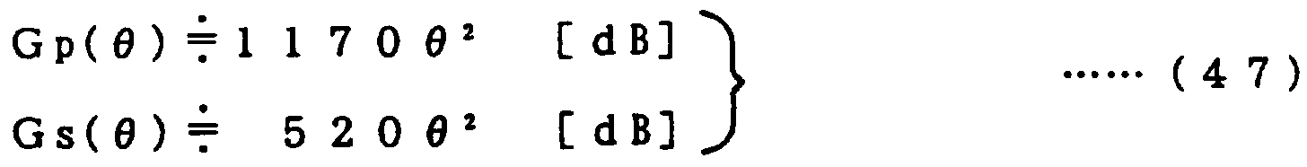

Claims
Priority Applications (3)
| Application Number | Priority Date | Filing Date | Title |
|---|---|---|---|
| KR1019970702507A KR970707458A (ko) | 1994-10-18 | 1995-10-17 | 액정표시장치(liquid crystal display unit) |
| US08/836,142 US6102545A (en) | 1994-10-18 | 1995-10-17 | Liquid crystal display unit |
| EP95934314A EP0802443A4 (en) | 1994-10-18 | 1995-10-17 | LIQUID CRYSTAL DISPLAY |
Applications Claiming Priority (2)
| Application Number | Priority Date | Filing Date | Title |
|---|---|---|---|
| JP25180094 | 1994-10-18 | ||
| JP6/251800 | 1994-10-18 |
Publications (1)
| Publication Number | Publication Date |
|---|---|
| WO1996012208A1 true WO1996012208A1 (fr) | 1996-04-25 |
Family
ID=17228121
Family Applications (1)
| Application Number | Title | Priority Date | Filing Date |
|---|---|---|---|
| PCT/JP1995/002123 WO1996012208A1 (fr) | 1994-10-18 | 1995-10-17 | Affichage a cristaux liquides |
Country Status (5)
| Country | Link |
|---|---|
| US (1) | US6102545A (ja) |
| EP (1) | EP0802443A4 (ja) |
| KR (1) | KR970707458A (ja) |
| CN (1) | CN1168726A (ja) |
| WO (1) | WO1996012208A1 (ja) |
Families Citing this family (21)
| Publication number | Priority date | Publication date | Assignee | Title |
|---|---|---|---|---|
| JPH0950081A (ja) * | 1995-08-08 | 1997-02-18 | Sony Corp | 透過型表示装置 |
| JP2000098296A (ja) * | 1998-09-17 | 2000-04-07 | Sharp Corp | 投影型カラー画像表示装置 |
| JP2001305520A (ja) * | 2000-04-24 | 2001-10-31 | Toshiba Corp | 液晶表示素子およびその製造方法 |
| US20010050815A1 (en) * | 2000-04-28 | 2001-12-13 | Jun Ishihara | Light separation device, blazed grating device, diffraction grating device, and illumination optical system |
| US6739724B2 (en) * | 2001-06-22 | 2004-05-25 | Seiko Epson Corporation | Illumination optical system and projector |
| AU2003901589A0 (en) * | 2003-04-04 | 2003-05-01 | Griffith University | Novel photoelectrichemical oxygen demand assay |
| EP1646895A1 (en) * | 2003-05-30 | 2006-04-19 | Koninklijke Philips Electronics N.V. | Compact efficient light collection optics for scrolling color illumination |
| JP2005221706A (ja) * | 2004-02-05 | 2005-08-18 | Nec Corp | 光源装置並びにこれを備えたプロジェクタ装置、照明装置及び液晶表示装置 |
| US7717578B2 (en) | 2004-03-11 | 2010-05-18 | Thomson Licensing | Multiple lamp illumination system with polarization recovery and integration |
| US20050231651A1 (en) * | 2004-04-14 | 2005-10-20 | Myers Timothy F | Scanning display system |
| US20070053190A1 (en) * | 2004-05-17 | 2007-03-08 | Koninklijke Philips Electronics N.V. | Compact efficient light collection optics for scrolling color illumination |
| US7023619B2 (en) * | 2004-06-17 | 2006-04-04 | Hewlett-Packard Development Company, L.P. | Digital projection system optical reflector having facets |
| KR100588060B1 (ko) * | 2005-06-30 | 2006-06-09 | 엘지전자 주식회사 | 재귀반사체 |
| JP2010513973A (ja) * | 2006-12-19 | 2010-04-30 | コーニンクレッカ フィリップス エレクトロニクス エヌ ヴィ | レンズ構造体及び製造方法並びに成形ポリマー品の製造 |
| US20110073495A1 (en) * | 2006-12-22 | 2011-03-31 | Aqua Diagnostic Pty Ltd | Water analysis |
| KR20090017442A (ko) * | 2007-08-14 | 2009-02-18 | 주식회사 엘지화학 | Lcd 백라이트 유닛용 집광 필름 |
| JP2010249966A (ja) | 2009-04-14 | 2010-11-04 | Hitachi Ltd | 光学エンジン |
| CN102859425A (zh) | 2010-04-27 | 2013-01-02 | 夏普株式会社 | 背光源系统和使用其的液晶显示装置 |
| TWI452360B (zh) | 2010-12-10 | 2014-09-11 | Ind Tech Res Inst | 準直光學元件、準直光學組件、準直光學陣列及準直光學模組 |
| US8351125B2 (en) * | 2010-12-10 | 2013-01-08 | Industrial Technology Research Institute | Directional light distributed optical element and directional light distributed optical assembly |
| JP7424246B2 (ja) * | 2020-08-19 | 2024-01-30 | セイコーエプソン株式会社 | 光源装置、画像表示装置、およびプロジェクター |
Citations (13)
| Publication number | Priority date | Publication date | Assignee | Title |
|---|---|---|---|---|
| JPS60169833A (ja) * | 1984-02-14 | 1985-09-03 | Seiko Epson Corp | パネル型表示装置 |
| JPS62150317A (ja) * | 1985-12-25 | 1987-07-04 | Casio Comput Co Ltd | カラ−液晶プロジエクタ |
| JPS62195984A (ja) * | 1986-02-24 | 1987-08-29 | Sony Corp | プロジエクタ |
| JPS63110422A (ja) * | 1986-10-29 | 1988-05-14 | Hitachi Ltd | 透過形液晶表示装置 |
| JPH01209481A (ja) * | 1988-02-18 | 1989-08-23 | Kawasaki Heavy Ind Ltd | 画像投影用液晶パネル構造 |
| JPH0233082U (ja) * | 1988-08-25 | 1990-03-01 | ||
| JPH0380222A (ja) * | 1990-03-17 | 1991-04-05 | Casio Comput Co Ltd | 液晶プロジェクタ |
| JPH0422938A (ja) * | 1990-05-18 | 1992-01-27 | Sony Corp | 液晶プロジェクタ装置 |
| JPH0478816A (ja) * | 1990-07-20 | 1992-03-12 | Canon Inc | 偏光照明装置及び該偏光照明装置を備える投写型表示装置 |
| JPH0478840A (ja) * | 1990-07-20 | 1992-03-12 | Dainippon Printing Co Ltd | 背面投影透過型スクリーン |
| JPH04270333A (ja) * | 1991-02-26 | 1992-09-25 | Dainippon Printing Co Ltd | プロジェクタ |
| JPH0634969A (ja) * | 1992-07-21 | 1994-02-10 | Nikon Corp | 液晶テレビジョン装置 |
| JPH06230384A (ja) * | 1992-08-11 | 1994-08-19 | Sharp Corp | 表示装置 |
Family Cites Families (18)
| Publication number | Priority date | Publication date | Assignee | Title |
|---|---|---|---|---|
| US4422135A (en) * | 1979-10-11 | 1983-12-20 | Kollmorgen Technologies Corporation | Annular illuminator |
| JPH077179B2 (ja) * | 1984-06-13 | 1995-01-30 | 株式会社日立製作所 | 画像投写装置 |
| GB8600021D0 (en) * | 1986-01-02 | 1986-02-12 | Rca Corp | Light box |
| JPS63298217A (ja) * | 1987-05-29 | 1988-12-06 | Hitachi Ltd | 透過形液晶表示装置 |
| JPH0233082A (ja) * | 1988-07-23 | 1990-02-02 | Hitachi Elevator Eng & Service Co Ltd | エレベータの戸の制御装置 |
| JP2726294B2 (ja) * | 1989-01-06 | 1998-03-11 | 株式会社日立製作所 | 液晶パネル式投写形ディスプレイ |
| US5142387A (en) * | 1990-04-11 | 1992-08-25 | Mitsubishi Denki Kabushiki Kaisha | Projection-type display device having light source means including a first and second concave mirrors |
| JP2622185B2 (ja) * | 1990-06-28 | 1997-06-18 | シャープ株式会社 | カラー液晶表示装置 |
| JP2902464B2 (ja) * | 1990-09-04 | 1999-06-07 | 旭光学工業株式会社 | 反射照明装置 |
| JP2643713B2 (ja) * | 1992-03-13 | 1997-08-20 | 株式会社日立製作所 | 液晶投写形ディスプレイ |
| JPH05264904A (ja) * | 1992-03-18 | 1993-10-15 | Canon Inc | 照明光学系および該照明光学系を用いた投写型画像表示装置 |
| US5459592A (en) * | 1992-04-24 | 1995-10-17 | Sharp Kabushiki Kaisha | Projection display system including a collimating tapered waveguide or lens with the normal to optical axis angle increasing toward the lens center |
| JP3207022B2 (ja) * | 1992-11-24 | 2001-09-10 | 株式会社日立製作所 | 投射型表示装置用光源、照明装置および液晶投射型表示装置 |
| JP2643755B2 (ja) * | 1993-02-26 | 1997-08-20 | 株式会社日立製作所 | 液晶ディスプレイ |
| US5594561A (en) * | 1993-03-31 | 1997-01-14 | Palomar Technologies Corporation | Flat panel display with elliptical diffuser and fiber optic plate |
| JPH0719029A (ja) * | 1993-06-30 | 1995-01-20 | Toyota Autom Loom Works Ltd | ディーゼル機関の排気ガス浄化装置 |
| JPH07162700A (ja) * | 1993-12-10 | 1995-06-23 | Hitachi Ltd | ディスプレイの一様性補正信号発生装置 |
| WO1997001787A1 (fr) * | 1995-06-26 | 1997-01-16 | Nissho Giken Kabushiki Kaisha | Appareil de projection |
-
1995
- 1995-10-17 WO PCT/JP1995/002123 patent/WO1996012208A1/ja not_active Application Discontinuation
- 1995-10-17 KR KR1019970702507A patent/KR970707458A/ko not_active Application Discontinuation
- 1995-10-17 CN CN95196657A patent/CN1168726A/zh active Pending
- 1995-10-17 EP EP95934314A patent/EP0802443A4/en not_active Withdrawn
- 1995-10-17 US US08/836,142 patent/US6102545A/en not_active Expired - Lifetime
Patent Citations (13)
| Publication number | Priority date | Publication date | Assignee | Title |
|---|---|---|---|---|
| JPS60169833A (ja) * | 1984-02-14 | 1985-09-03 | Seiko Epson Corp | パネル型表示装置 |
| JPS62150317A (ja) * | 1985-12-25 | 1987-07-04 | Casio Comput Co Ltd | カラ−液晶プロジエクタ |
| JPS62195984A (ja) * | 1986-02-24 | 1987-08-29 | Sony Corp | プロジエクタ |
| JPS63110422A (ja) * | 1986-10-29 | 1988-05-14 | Hitachi Ltd | 透過形液晶表示装置 |
| JPH01209481A (ja) * | 1988-02-18 | 1989-08-23 | Kawasaki Heavy Ind Ltd | 画像投影用液晶パネル構造 |
| JPH0233082U (ja) * | 1988-08-25 | 1990-03-01 | ||
| JPH0380222A (ja) * | 1990-03-17 | 1991-04-05 | Casio Comput Co Ltd | 液晶プロジェクタ |
| JPH0422938A (ja) * | 1990-05-18 | 1992-01-27 | Sony Corp | 液晶プロジェクタ装置 |
| JPH0478816A (ja) * | 1990-07-20 | 1992-03-12 | Canon Inc | 偏光照明装置及び該偏光照明装置を備える投写型表示装置 |
| JPH0478840A (ja) * | 1990-07-20 | 1992-03-12 | Dainippon Printing Co Ltd | 背面投影透過型スクリーン |
| JPH04270333A (ja) * | 1991-02-26 | 1992-09-25 | Dainippon Printing Co Ltd | プロジェクタ |
| JPH0634969A (ja) * | 1992-07-21 | 1994-02-10 | Nikon Corp | 液晶テレビジョン装置 |
| JPH06230384A (ja) * | 1992-08-11 | 1994-08-19 | Sharp Corp | 表示装置 |
Non-Patent Citations (1)
| Title |
|---|
| See also references of EP0802443A4 * |
Also Published As
| Publication number | Publication date |
|---|---|
| EP0802443A1 (en) | 1997-10-22 |
| EP0802443A4 (en) | 1999-03-24 |
| CN1168726A (zh) | 1997-12-24 |
| KR970707458A (ko) | 1997-12-01 |
| US6102545A (en) | 2000-08-15 |
Similar Documents
| Publication | Publication Date | Title |
|---|---|---|
| WO1996012208A1 (fr) | Affichage a cristaux liquides | |
| US6575580B2 (en) | Lighting system and projection type display unit using thereof | |
| JP4278980B2 (ja) | ディスプレイパネル用光学系 | |
| US6485145B1 (en) | Optical system for display panel | |
| JP2589834B2 (ja) | 改良されたビデオディスプレイシステム | |
| CN101950084B (zh) | 影像显示装置和应用该影像显示装置的三维影像显示装置 | |
| CN101351745B (zh) | 投影系统及其光束调制方法 | |
| WO1994022042A1 (en) | Projection type display device | |
| JP2002523812A (ja) | 超薄型光学パネル及び超薄型光学パネルの製造方法 | |
| KR20010042282A (ko) | 회절, 산란을 이루는 광학소자를 사용한 투광, 표시장치 | |
| US11073749B2 (en) | Projection system, projection-type image display apparatus, and imaging apparatus | |
| JP2013532313A (ja) | オフセットを有する軸上投写レンズ | |
| TW523609B (en) | Illumination optical system and projector using the same | |
| US6719430B2 (en) | Precision optical system for display panel | |
| CN111999870B (zh) | 用于图像投影的变焦镜头及图像投影装置 | |
| JP2001188111A (ja) | プリズム、投写光学系及び投写型表示装置 | |
| US7421180B2 (en) | Light guide apparatus for use in rear projection display environments | |
| JP2001166118A (ja) | プリズム、投写光学系及び投写型表示装置 | |
| JPH08190080A (ja) | 液晶ディスプレイ装置 | |
| JP3669933B2 (ja) | 照明装置および投写型表示装置 | |
| JPH08227103A (ja) | 投射型表示装置 | |
| CN220455659U (zh) | 一种投影系统和投影设备 | |
| US20230418068A1 (en) | Anamorphic directional illumination device | |
| TW202221378A (zh) | 投影鏡頭及投影裝置 | |
| JP2024514639A (ja) | 投影装置、投影レンズアセンブリ及び投影システム |
Legal Events
| Date | Code | Title | Description |
|---|---|---|---|
| WWE | Wipo information: entry into national phase |
Ref document number: 95196657.X Country of ref document: CN |
|
| AK | Designated states |
Kind code of ref document: A1 Designated state(s): CN KR US |
|
| AL | Designated countries for regional patents |
Kind code of ref document: A1 Designated state(s): AT BE CH DE DK ES FR GB GR IE IT LU MC NL PT SE |
|
| DFPE | Request for preliminary examination filed prior to expiration of 19th month from priority date (pct application filed before 20040101) | ||
| 121 | Ep: the epo has been informed by wipo that ep was designated in this application | ||
| WWE | Wipo information: entry into national phase |
Ref document number: 1995934314 Country of ref document: EP |
|
| WWE | Wipo information: entry into national phase |
Ref document number: 08836142 Country of ref document: US Ref document number: 1019970702507 Country of ref document: KR |
|
| WWP | Wipo information: published in national office |
Ref document number: 1995934314 Country of ref document: EP |
|
| WWP | Wipo information: published in national office |
Ref document number: 1019970702507 Country of ref document: KR |
|
| WWR | Wipo information: refused in national office |
Ref document number: 1019970702507 Country of ref document: KR |
|
| WWW | Wipo information: withdrawn in national office |
Ref document number: 1995934314 Country of ref document: EP |