US9988007B2 - Occlusion control device - Google Patents
Occlusion control device Download PDFInfo
- Publication number
- US9988007B2 US9988007B2 US15/568,394 US201515568394A US9988007B2 US 9988007 B2 US9988007 B2 US 9988007B2 US 201515568394 A US201515568394 A US 201515568394A US 9988007 B2 US9988007 B2 US 9988007B2
- Authority
- US
- United States
- Prior art keywords
- close observation
- host vehicle
- proportion
- blind spot
- control device
- Prior art date
- Legal status (The legal status is an assumption and is not a legal conclusion. Google has not performed a legal analysis and makes no representation as to the accuracy of the status listed.)
- Active
Links
- 230000010485 coping Effects 0.000 claims abstract description 66
- 230000006399 behavior Effects 0.000 claims abstract description 17
- 238000000034 method Methods 0.000 description 9
- 230000003247 decreasing effect Effects 0.000 description 5
- 230000001133 acceleration Effects 0.000 description 3
- 238000004364 calculation method Methods 0.000 description 2
- 238000004590 computer program Methods 0.000 description 2
- 238000010586 diagram Methods 0.000 description 2
- 230000004438 eyesight Effects 0.000 description 2
- 230000004397 blinking Effects 0.000 description 1
- 230000007423 decrease Effects 0.000 description 1
- 230000000694 effects Effects 0.000 description 1
- 230000006870 function Effects 0.000 description 1
- 230000003068 static effect Effects 0.000 description 1
- 230000002123 temporal effect Effects 0.000 description 1
Images


Classifications
-
- G—PHYSICS
- G06—COMPUTING; CALCULATING OR COUNTING
- G06V—IMAGE OR VIDEO RECOGNITION OR UNDERSTANDING
- G06V20/00—Scenes; Scene-specific elements
- G06V20/50—Context or environment of the image
- G06V20/56—Context or environment of the image exterior to a vehicle by using sensors mounted on the vehicle
-
- G—PHYSICS
- G08—SIGNALLING
- G08G—TRAFFIC CONTROL SYSTEMS
- G08G1/00—Traffic control systems for road vehicles
- G08G1/16—Anti-collision systems
-
- B—PERFORMING OPERATIONS; TRANSPORTING
- B60—VEHICLES IN GENERAL
- B60R—VEHICLES, VEHICLE FITTINGS, OR VEHICLE PARTS, NOT OTHERWISE PROVIDED FOR
- B60R21/00—Arrangements or fittings on vehicles for protecting or preventing injuries to occupants or pedestrians in case of accidents or other traffic risks
- B60R21/01—Electrical circuits for triggering passive safety arrangements, e.g. airbags, safety belt tighteners, in case of vehicle accidents or impending vehicle accidents
- B60R21/013—Electrical circuits for triggering passive safety arrangements, e.g. airbags, safety belt tighteners, in case of vehicle accidents or impending vehicle accidents including means for detecting collisions, impending collisions or roll-over
- B60R21/0132—Electrical circuits for triggering passive safety arrangements, e.g. airbags, safety belt tighteners, in case of vehicle accidents or impending vehicle accidents including means for detecting collisions, impending collisions or roll-over responsive to vehicle motion parameters, e.g. to vehicle longitudinal or transversal deceleration or speed value
-
- B—PERFORMING OPERATIONS; TRANSPORTING
- B60—VEHICLES IN GENERAL
- B60W—CONJOINT CONTROL OF VEHICLE SUB-UNITS OF DIFFERENT TYPE OR DIFFERENT FUNCTION; CONTROL SYSTEMS SPECIALLY ADAPTED FOR HYBRID VEHICLES; ROAD VEHICLE DRIVE CONTROL SYSTEMS FOR PURPOSES NOT RELATED TO THE CONTROL OF A PARTICULAR SUB-UNIT
- B60W30/00—Purposes of road vehicle drive control systems not related to the control of a particular sub-unit, e.g. of systems using conjoint control of vehicle sub-units
- B60W30/08—Active safety systems predicting or avoiding probable or impending collision or attempting to minimise its consequences
- B60W30/095—Predicting travel path or likelihood of collision
-
- G—PHYSICS
- G06—COMPUTING; CALCULATING OR COUNTING
- G06F—ELECTRIC DIGITAL DATA PROCESSING
- G06F3/00—Input arrangements for transferring data to be processed into a form capable of being handled by the computer; Output arrangements for transferring data from processing unit to output unit, e.g. interface arrangements
- G06F3/14—Digital output to display device ; Cooperation and interconnection of the display device with other functional units
- G06F3/147—Digital output to display device ; Cooperation and interconnection of the display device with other functional units using display panels
-
- G—PHYSICS
- G08—SIGNALLING
- G08G—TRAFFIC CONTROL SYSTEMS
- G08G1/00—Traffic control systems for road vehicles
- G08G1/16—Anti-collision systems
- G08G1/167—Driving aids for lane monitoring, lane changing, e.g. blind spot detection
-
- B—PERFORMING OPERATIONS; TRANSPORTING
- B60—VEHICLES IN GENERAL
- B60R—VEHICLES, VEHICLE FITTINGS, OR VEHICLE PARTS, NOT OTHERWISE PROVIDED FOR
- B60R1/00—Optical viewing arrangements; Real-time viewing arrangements for drivers or passengers using optical image capturing systems, e.g. cameras or video systems specially adapted for use in or on vehicles
- B60R1/12—Mirror assemblies combined with other articles, e.g. clocks
- B60R2001/1253—Mirror assemblies combined with other articles, e.g. clocks with cameras, video cameras or video screens
-
- B—PERFORMING OPERATIONS; TRANSPORTING
- B60—VEHICLES IN GENERAL
- B60R—VEHICLES, VEHICLE FITTINGS, OR VEHICLE PARTS, NOT OTHERWISE PROVIDED FOR
- B60R21/00—Arrangements or fittings on vehicles for protecting or preventing injuries to occupants or pedestrians in case of accidents or other traffic risks
Definitions
- the present invention relates to an occlusion control device.
- a driving assistance device has been known for predicting a risk of contact between a host vehicle and an obstacle around the host vehicle in a case where the host vehicle is traveling under driving behavior according to at least one or more normative behavior candidates, the normative behavior candidates being candidates for normative driving behavior of the host vehicle for a situation around the host vehicle (see Japanese Patent Application Publication No. 2011-096105).
- Japanese Patent Application Publication No. 2011-096105 calculates a potential contact risk and determines the driving behavior based on the contact risk.
- An object of the present invention is to provide an occlusion control device that suppresses driving behavior excessively reducing a risk of contact with a moving object.
- An occlusion control device calculates proportion of the blind spot for the host vehicle with respect to a close observation detecting criterion, which is set in one or more close observation region in which presence or absence of a moving object should be closely observed.
- FIG. 1 is a block diagram showing an overall configuration of an occlusion control device 1 according to a first embodiment
- FIG. 2 is a block diagram showing multiple processing circuits configured by an arithmetic circuit 17 a;
- FIG. 3 is a flowchart showing an example of an occlusion control method that uses the occlusion control device 1 shown in FIG. 1 and FIG. 2 ;
- FIG. 4 shows an example where a close observation detecting criterion is a close observation frame 31 surrounding an outer periphery of a close observation region
- FIG. 4( a ) is a plan view showing a position of a host vehicle 41 at time B shown in FIG. 4( b ) ;
- FIG. 4( b ) is a graph showing a temporal change of speed of the host vehicle 41 and proportion calculated by a visibility proportion calculator 28 ;
- FIG. 4( c ) shows a position of the host vehicle 41 at time A shown in FIG. 4( b ) ;
- FIG. 4( d ) shows a position of the host vehicle 41 at time C shown in FIG. 4( b ) ;
- FIG. 5 is a plan view showing an example of a close observation point group including multiple close observation points
- FIG. 6 is a plan view showing an example of a line bundle including one or more close observation line segments 44 ;
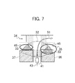
- FIG. 7 is a plan view showing an example of the close observation frame 31 shaped in an oval 45 ;
- FIG. 8( a ) is a plan view showing an example of past accident data ( 46 , 47 );
- FIG. 8( b ) is a plan view showing an example of a close observation frame 48 to which weighting is applied;
- FIG. 8( c ) is a graph showing gauss distribution of accident probability Z as an example of the weighting
- FIG. 9 is a graph showing an example of a starting threshold (Ts), which is a criterion for determining whether to start blind spot coping behavior;
- FIG. 10 is a graph showing an example of an ending threshold (Te), which is a criterion for determining whether to end the blind spot coping behavior;
- FIG. 11 is a plan view showing an example of close observation frames ( 31 aa , 31 ab ) that are set in a case where a moving object (another vehicle 53 ) exists in a close observation region 31 a;
- FIG. 12 is a plan view showing an example of blind spot coping control for a scheduled traveling route 51 of the host vehicle 41 ;
- FIG. 12( a ) shows the blind spot coping control for turning right at an intersection
- FIG. 12( b ) shows the blind spot coping control for going straight through the intersection.
- the occlusion control device 1 calculates proportion of a blind spot 33 for a host vehicle 41 with respect to a close observation detecting criterion ( 31 ) set on a map, determines coping behavior of the host vehicle 41 based on this proportion, and performs driving assistance for the host vehicle 41 according to this coping behavior.
- the close observation detecting criterion ( 31 ) is a criterion set in one or more close observation regions in which presence or absence of a moving object should be closely observed while the host vehicle 41 is traveling.
- the close observation detecting criterion ( 31 ) is illustrated with one or more frames (close observation frames 31 ; FIGS.
- the blind spot 33 for the host vehicle 41 also includes a blind spot for a camera or a laser sensor mounted in the host vehicle.
- the coping behavior of the host vehicle 41 at least includes coping behavior that takes account of the blind spot 33 for the host vehicle 41 (blind spot coping behavior) and normal coping behavior that does not take account of the blind spot 33 for the host vehicle 41 (normal coping behavior).
- the occlusion control device 1 includes a GPS 11 , a map database 12 , a vehicle-mounted camera 13 and a laser sensor 14 , an operating unit 15 , a close observation frame database 16 , and a arithmetic circuit 17 a .
- the GPS 11 is an example of a host vehicle position detector that detects a current position and an orientation of the host vehicle.
- the GPS 11 receives an electric wave from a NAVSTAR satellite in a global positioning system and determines the position and the orientation of the host vehicle in real time.
- the host vehicle position detector may be a yaw rate sensor and a vehicle speed sensor for performing odometry (self position estimation) or may be used in combination with the GPS 11 .
- the map database 12 is an example of a map storage for storing map data showing shapes of roads on which the host vehicle can travel.
- the close observation frame database 16 stores data on a position and a size of the close observation frame 31 (see FIG. 4 ), which is an example of the close observation detecting criterion, on the map.
- This embodiment shows an example of storing the map data and the data on the close observation frame in different databases, respectively; however, it is not limited thereto.
- Map data in which the close observation frame is set in advance may be stored in one database.
- the close observation detecting criterion including the close observation frame is set in the one or more close observation regions on the map in which presence or absence of the moving object should be closely observed.
- the “moving object” includes a vehicle and a light vehicle that are traveling or standing on the road as well as a pedestrian.
- the vehicle-mounted camera 13 and the laser sensor 14 are an example of an obstacle detector that detects positions of obstacles around the host vehicle.
- the vehicle-mounted camera 13 is mounted in the host vehicle and takes an image of surroundings of the host vehicle to obtain a surroundings image.
- the arithmetic circuit 17 a analyzes the surroundings image to determine presence or absence and the position of the obstacle.
- buildings 36 , 37 present around the host vehicle see FIG. 4
- a wall, a tree, a signboard that are fixed on the ground the “obstacle” also includes the above-mentioned moving object.
- the laser sensor 14 emits pulses of laser light and detects light reflected from the obstacle, thereby detecting a distance and a direction from the host vehicle to the obstacle.
- the operating unit 15 includes a touch panel, a steering switch, and the like, which are members for receiving an instruction from the occupant of the host vehicle, arranged on a mike and an instrument panel.
- the arithmetic circuit 17 a uses information on the host vehicle position, the map, the obstacle, and the close observation frame to calculate proportion of the blind spot 33 for the host vehicle 41 with respect to the close observation frame 31 . Then, the arithmetic circuit 17 a determines the coping behavior of the host vehicle 41 based on this proportion and performs a series of computing processing for performing the driving assistance for the host vehicle 41 .
- the arithmetic circuit 17 a is a general-purpose microcomputer including a CPU, a RAM, a ROM, a memory, and an input/output control circuit.
- a computer program in which the series of arithmetic processes is described is installed in the microcomputer in advance. Executing the computer program, the micro computer constructs multiple processing circuits for executing the above-mentioned series of arithmetic processes.
- the multiple processing circuits constructed by the arithmetic circuit 17 a are described later by reference to FIG. 2 .
- the arithmetic circuit 17 a includes a scene understanding unit 21 and a driving assistance unit 22 .
- the scene understanding unit 21 calculates proportion of the blind spot for the host vehicle and determines the coping behavior of the host vehicle based on this proportion.
- the driving assistance unit 22 performs the driving assistance for the host vehicle.
- the driving assistance may be autonomous driving control that the driving assistance unit 22 drives various actuators so that the driving assistance unit 22 proactively performs all driving operation including steering operation and pedal operation.
- driving operation that the driver should perform may be indicated via the five senses such as hearing, eyesight, and touch of the driver.
- the scene understanding unit 21 includes a map obtaining unit 23 , a route calculator 24 , a close observation frame obtaining unit 25 , a sensing range calculator 26 , a blind spot calculator 27 , an visibility proportion calculator 28 (proportion calculator), and a proportion determining unit 29 (behavior determining unit).
- the route calculator 24 calculates a scheduled traveling route 51 (see FIG. 4 ) from the current position of the host vehicle determined by the GPS 11 to a destination that the operating unit 15 receives. Note that, in the embodiments, a description for a case where the occlusion control device 1 has a function of computing the scheduled traveling route by itself is given. However, the occlusion control device 1 may obtain the scheduled traveling route 51 calculated by another device from outside.
- the map obtaining unit 23 obtains the map data according to the scheduled traveling route 51 from the map database 12 .
- a digital map can be used as the map data.
- the digital map includes curb information indicating a position of a curb or road network information.
- the curb information is used for calculating a travelable region of the host vehicle.
- the road network information is used for finding a region where the host vehicle 41 can travel at the later-mentioned time.
- the close observation frame obtaining unit 25 obtains data on the position and the size of the close observation frame 31 on the map from the close observation frame database 16 .
- the map obtaining unit 23 uses the obtained data on the close observation frame 31 to generate map data in which the close observation frame 31 is set. In this way, the map obtaining unit 23 can obtain the map data with the close observation frame 31 set in the one or more close observation region in which presence or absence of the moving object should be closely observed.
- the sensing range calculator 26 calculates a sensing range 32 (see FIG. 4 ) on the map.
- the “sensing range 32 ” represents a range in which the vehicle-mounted camera 13 and the laser sensor 14 can detect the obstacle if there is no obstacle around the host vehicle 41 .
- the sensing range 32 can be calculated for each of the vehicle-mounted camera 13 and the laser sensor 14 while the sensing range 32 is determined by the attached positions and angles of the vehicle-mounted camera 13 and the laser sensor 14 with respect to the host vehicle 41 .
- the sensing range 32 on the map can be calculated based on the current position and orientation of the host vehicle 41 as well as the map data.
- the blind spot calculator 27 calculates presence or absence of the blind spot 33 for the host vehicle 41 created by the obstacle and the range of the blind spot 33 . Within the blind spots for the host vehicle 41 created by the obstacle (e.g., the buildings 36 , 37 ), the blind spot calculator 27 detects a part that overlaps with the sensing range 32 as the blind spot 33 for the host vehicle.
- the obstacle e.g., the buildings 36 , 37
- the visibility proportion calculator 28 calculates proportion of the blind spot 33 for the host vehicle 41 with respect to the close observation frame 31 (the close observation detecting criterion). For example, with respect to the entire area of the close observation frame 31 , the visibility proportion calculator 28 calculates proportion of the area of the close observation frame that overlaps with the blind spot 33 for the host vehicle.
- the proportion determining unit 29 determines the coping behavior of the host vehicle 41 . Specifically, based on the above-mentioned proportion, the proportion determining unit 29 selects either the blind spot coping behavior or the normal coping behavior.
- FIG. 4 an example where the close observation detecting criterion is the close observation frames 31 surrounding the outer peripheries of the close observation regions is described.
- the FIGS. 4( a ), 4( c ), and 4( d ) shows the host vehicle 41 traveling along the scheduled traveling route 51 that turns right at an intersection of a trifurcate road where three roads converge. Since the buildings 36 and 37 as the obstacle are standing on both sides of the host vehicle 41 entering into the intersection from a traveling direction 43 , the blind spots 33 for the host vehicle 41 are created by the buildings 36 and 37 . As described above, the blind spots 33 are calculated by the blind spot calculator 27 .
- the close observation frame obtaining unit 25 obtains the close observation frames 31 in which presence or absence of the moving object should be closely observed for the scheduled traveling route 51 turning right at the intersection. With respect to the area of the close observation frame 31 , the visibility proportion calculator 28 calculates proportion of each area of the close observation frames 31 that overlaps with the corresponding blind spot 33 for the host vehicle 41 . As shown in FIG. 4( a ) , the close observation frames 31 are set in areas that tend to be the blind spots 33 for the host vehicle 41 because of the buildings 36 and 37 .
- the visibility proportion calculator 28 performs no proportion calculating operation; thus, the proportion is 0%.
- the driving assistance unit 22 performs the normal coping behavior.
- the visibility proportion calculator 28 starts proportion calculating.
- proportion of each area of the close observation frames 31 overlapping with the blind spot 33 for the host vehicle 41 becomes greater than a predetermined value (e.g., 20%).
- the proportion determining unit 29 selects the blind spot coping behavior as the coping behavior of the host vehicle 41 .
- the vehicle is able to look the entirety of the close observation frames 31 .
- proportion of each area of the close observation frames 31 overlapping with the blind spot 33 for the host vehicle 41 becomes 0%.
- the proportion determining unit 29 selects the normal coping behavior as the coping behavior of the host vehicle 41 . In this way, using the close observation frame 31 and the sensing range 32 , the overlapping proportion of the blind spot of the host vehicle and the close observation frame 31 can be quantified as a degree of risk. This contributes to digitization of the risk of contact with the moving object.
- a vehicle speed of the host vehicle 41 is a speed based on the normal coping behavior.
- the host vehicle 41 once decelerates to zero. Thereafter, the host vehicle 41 crawls until the visibility proportion decreases to smaller than or equal to the predetermined value and moves to a position where the host vehicle 41 is able to look the entirety of the close observation frames 31 . Getting back to the normal coping behavior, the host vehicle 41 stops temporarily and then resumes the operation for turning right.
- FIG. 3 an example of an occlusion control method according to the first embodiment is described.
- the occlusion control method is performed repeatedly by a predetermined cycle and is ended with termination of the occlusion control device.
- step S 01 the map obtaining unit 23 obtains the map data from the map database 12 .
- the processing proceeds to step S 03 ; based on the information on the position and the destination of the host vehicle 41 , the route calculator 24 computes the scheduled traveling route 51 of the host vehicle. Note that the map data of an area according to the scheduled traveling route 51 may be obtained after the route computing. This makes it possible to reduce an amount of the obtained data.
- step S 05 the close observation frame obtaining unit 25 obtains the data on the positions and the sizes of the close observation frames 31 on the map from the close observation frame database 16 .
- the map obtaining unit 23 uses the obtained data on the close observation frames 31 to generate the map data in which the close observation frames 31 are set.
- the processing proceeds to step S 07 ; the sensing range calculator 26 computes the sensing range 32 on the map based on the current position and orientation of the host vehicle as well as the map data.
- step S 09 within the blind spots for the host vehicle 41 created by the obstacle (e.g., the buildings 36 , 37 ), the blind spot calculator 27 detects a part that overlaps with the sensing range 32 as the blind spot 33 for the host vehicle. Specifically, the blind spot calculator 27 obtains position information of the buildings 36 , 37 present around the vehicle that is detected by the vehicle-mounted camera 13 and the laser sensor 14 . By comparing the sensing range 32 and the positions of the buildings 36 , 37 , the blind spot calculator 27 can calculate the blind spots 33 for the host vehicle that overlap with the sensing range 32 .
- the blind spot calculator 27 can calculate the blind spots 33 for the host vehicle that overlap with the sensing range 32 .
- step S 11 the scene understanding unit 21 determines whether the close observation frames 31 and the blind spots 33 of the host vehicle overlap with each other. If they overlap with each other (YES in S 11 ), the processing proceeds to step S 13 . If they do not overlap with each other (NO in S 11 ), the processing returns to step S 07 .
- step S 13 with respect to the entire area of the close observation frame 31 , the visibility proportion calculator 28 calculates proportion of each area of the close observation frames that overlaps with the blind spot 33 for the host vehicle.
- the coping behavior switches from the normal coping behavior to the blind spot coping behavior (S 19 ). This makes the vehicle speed decelerate from a usual speed to zero. Performing such blind spot coping behavior lowers the contact risk in a scene with bad visibility and allows safe traveling. Then, the blind spot coping behavior is continued until the proportion becomes smaller than the predetermined ending threshold (Te). Specifically, as shown in FIG. 10 , the host vehicle is crawled and moved until the proportion becomes smaller than the predetermined ending threshold (Te). When the proportion becomes smaller than the predetermined ending threshold (Ts), the host vehicle is stopped.
- the starting threshold (Ts) and the ending threshold (Te) may be the same value; however, the ending threshold (Te) is desirably smaller than the starting threshold (Ts) so that hysteresis is made. This improves stability of a vehicle control system. For example, when the starting threshold (Ts) is set to 10%, the ending threshold (Te) may be set to 5%.
- the vehicle in a case where the moving object is detected in the region with good visibility while the vehicle is moving to make the proportion smaller than the predetermined ending threshold (Te), the vehicle is stopped. Otherwise, if moving speed of the moving object is slow, the vehicle may be accelerated to pass through in front of the moving object.
- Te predetermined ending threshold
- Determining the coping behavior of the host vehicle 41 based on the proportion of the blind spot 33 for the host vehicle 41 with respect to the close observation frame 31 (close observation detecting criterion) can suppress the driving behavior excessively focusing on safety.
- the driving behavior excessively focusing on safety can be suppressed, and discomfort that surrounding people feel can be lessened.
- the visibility proportion calculator 28 calculates proportion of the area of the close observation frame 31 that overlaps with the blind spot 33 of the host vehicle 41 . Since the coping behavior is determined according to area ratio between the blind spot 33 and the frame surrounding the outer periphery of the close observation region, risk computing with high accuracy can be achieved with a simple model.
- the proportion determining unit 29 decides to start the coping behavior that takes account of the blind spot 33 for the host vehicle 41 . Switching the traveling control based on the starting threshold (Ts) as a boundary can achieve appropriate control for each scene. Performing the coping behavior excessively reducing the contact risk is suppressed.
- the starting threshold (Ts) is set small. In this way, sudden speed control or steering control when starting control is suppressed, and thus the control can be started smoothly.
- the driving assistance unit 22 allows the host vehicle to move until the proportion becomes smaller than the predetermined ending threshold (Te), and allows the host vehicle to stop thereafter. In this way, safe traveling can be performed even in a situation with bad visibility.
- the close observation detecting criterion may be a close observation point group including multiple close observation points 42 provided in the close observation region.
- the visibility proportion calculator 28 calculates proportion of the number of the close observation points 42 that overlap with the blind spots 33 for the host vehicle 41 .
- Other configuration and operation procedure are the same as that in the first embodiment; thus, descriptions thereof are omitted.
- the close observation points 42 are arranged irregularly within the close observation region.
- density distribution of the close observation points 42 within the close observation region changes according to magnitude of the contact risk.
- the close observation points 42 are distributed in high density at: a position where the moving object is likely to exist; a position with bad visibility; or a position where the risk of having the contact between the moving object and the host vehicle 41 is high if the moving object exists. This makes it possible to calculate appropriate proportion according to the contact risk.
- the visibility proportion calculator 28 just simply obtains the number of the close observation points 42 that overlap with the blind spot 33 for the host vehicle 41 .
- the starting threshold (Ts) and the ending threshold (Te) can be determined based on the number of the close observation points 42 .
- the proportion may be calculated like the first embodiment by using the area ratio between the overlapping part and the close observation frame surrounding an outer periphery of the close observation point 42 . That is, as far as computing processing load allows, each close observation point 42 can be used as one or more close observation frame 31 in FIG. 4 .
- the proportion can be simply obtained from the number of the close observation points by setting the close observation point group including the multiple close observation points 42 provided in the close observation region as the close observation detecting criterion.
- risk computing with high accuracy can be achieved without increasing calculation load.
- the close observation detecting criterion may be a line bundle including one or more close observation line segments 44 provided in the close observation region.
- the visibility proportion calculator 28 calculates proportion of the lengths of the close observation line segments 44 that overlap with the blind spot 33 for the host vehicle 41 .
- Other configuration and operation procedure are the same as that in the first embodiment; thus, descriptions thereof are omitted.
- the lengths, the number, and arrangement of the close observation line segments 44 can be changed arbitrarily. According to the magnitude of the contact risk, density distribution of the close observation line segments 44 within the close observation region is changed. That is, the close observation line segments 44 are distributed in high density at: a position where the moving object is likely to exist; a position with bad visibility; or a position where the risk of having the contact between the moving object and the host vehicle 41 is high if the moving object exists. This makes it possible to calculate appropriate proportion according to the contact risk.
- the visibility proportion calculator 28 may just simply obtain the length of the close observation line segment 44 that overlap with the blind spot 33 for the host vehicle 41 .
- the starting threshold (Ts) and the ending threshold (Te) can be determined based on the length of the close observation line segment 44 .
- the proportion can be simply obtained from the length of the close observation line segment 44 by setting the one or more close observation line segments 44 provided in the close observation region as the close observation detecting criterion.
- risk computing with high accuracy can be achieved without increasing calculation load.
- the close observation frame 31 shown in FIG. 4 can be interpreted as a line bundle including four close observation line segments 44 provided in the close observation region.
- the visibility proportion calculator 28 may just calculate proportion of the length of the close observation frame 31 that overlaps with the blind spot 33 for the host vehicle 41 with respect to the total length of the close observation frame 31 .
- the whole close observation frame 31 may be one line segment including one curved line as shown in FIG. 7 .
- the close observation frame 31 is not limited to be a quadrangle as shown in FIG. 4 ; for example, the close observation frame 31 may be an oval 45 , a true circle, a triangle, or a polygon with five or more corners.
- proportion of the blind spot that overlaps with the area surrounded by the frame may be calculated like the first embodiment.
- the close observation detecting criterion may include weighting that is changed according to a position on the map.
- proportion of the blind spot for the host vehicle with respect to the close observation detecting criterion changes according to the weighting applied to the position on the map where the close observation detecting criterion overlaps with the blind spot for the host vehicle.
- the close observation detecting criterion is the close observation frame
- proportion of the area where the close observation frame and the blind spot for the host vehicle overlap with each other with respect to the entire area of the close observation frame changes according to the weighting.
- FIG. 8 shows an example of a close observation frame 48 to which weighting is applied.
- the close observation frame 48 includes overlapped multiple (three in FIG. 8 ) ovals with different sizes.
- each oval is applied with information on accident probability Z as an example of the weighting.
- an inner small oval is applied with information indicating the accident probability Z that is possibility higher than that associated with an outer larger oval.
- the contact risk is higher in a case where the blind spot 33 for the host vehicle 41 overlaps with the inner smaller oval than in a case where the blind spot 33 for the host vehicle 41 overlaps with the outer larger oval, and the proportion (visibility proportion) becomes greater.
- the information for the accident probability Z may be obtained by downloading past accident data ( 46 , 47 ) from an accident information management server as shown in FIG. 8( a ) , for example.
- a position on the map to which high accident probability Z is applied may be not only a position where an accident is occurred in the past, but may also be another position that is similar to the position where an accident is occurred. For example, if there was an accident of hitting another vehicle when turning right or left at an intersection, the high accident probability Z can also be applied to a position where similar accident can be occurred in a case of entering into different intersection or the same intersection from another direction.
- a value of the accident probability Z may be changed according to a detail of the accident.
- the accident probability Z of a fatal accident may be higher than that of a property damage accident.
- Distribution of the accident probability Z shown in FIG. 8( c ) can be calculated as gauss distribution, for example.
- proportion of the blind spot 33 for the host vehicle 41 with respect to the close observation detecting criterion is changed according to the weighting (the accident probability Z) applied to the position on the map that overlaps with the blind spot 33 for the host vehicle 41 . This makes it possible to accurately evaluate the contact risk, and to calculate appropriate proportion according to the contact risk.
- the close observation detecting criterion is made of the oval frame.
- the close observation line segment and the close observation point can also be weighted in the same way.
- the close observation detecting criterion may be changed according to a date and time, an environment around the host vehicle 41 , or a way of motion of the moving object present around the host vehicle 41 .
- the close observation detecting criterion is changed according to the date and time.
- the close observation detecting criterion is set. If the traffic signal operates normally, no close observation detecting criterion is set. At a specific spot where a traffic amount is increased according to the date and time such as a holiday, the close observation detecting criterion is set widely. Alternatively, on the date and time when the traffic amount is increased, the starting threshold and the ending threshold of the blind spot coping control are decreased. This lowers the contact risk and improves safety.
- FIG. 11 An example where the close observation detecting criterion is changed according to the way of motion of the moving object present around the host vehicle 41 is described below.
- a side closer to the host vehicle 41 and a side farther from the host vehicle 41 may be respectively applied with divided close observation frames ( 31 aa , 31 ab ).
- the close observation frame 31 ab in the closer side is set for detecting a pedestrian
- the close observation frame 31 aa in the farther side is set for detecting a two-wheel vehicle.
- Different close observation detecting criteria can be set for a case where the other vehicle 53 is standing at a stop line on an entry of the intersection and for a case where the other vehicle 53 is traveling around the stop line.
- the close observation detecting criterion is the close observation frame
- a close observation frame with a short length in a traveling direction of the other vehicle 53 is set as the speed of the other vehicle 53 is higher
- a close observation frame with a long length in the traveling direction of the other vehicle 53 is set.
- the reason why the length of the close observation frame made long when the other vehicle 53 is standing is that long-distance vision is needed for predicting the two-wheel vehicle coming into the close observation region.
- the starting threshold and the ending threshold of the blind spot coping control are decreased. This makes it possible to lower the contact risk and to improve safety.
- Safety can be improved under a situation such as a situation where the road is crowded on holiday or during commuting time, at sunset time, or at night time, where it is difficult for the other vehicle to confirm safety around the vehicle.
- the blind spot coping control for the speed of the host vehicle 41 has been described as shown in FIG. 4( b ) ; however, the blind spot coping control is not only for the speed of the host vehicle 41 but also for the scheduled traveling route 51 of the host vehicle 41 .
- the host vehicle 41 turns right at the intersection along the scheduled traveling route 51 .
- the host vehicle 41 is started to move toward the left side before entering into the intersection and turns right at the intersection along a scheduled traveling route 52 that is on the outer side of the scheduled traveling route 51 .
- the blind spot that overlaps with the close observation region 31 a can be decreased when entering into the intersection. This makes it possible to allow the host vehicle 41 to pass through the intersection safely without excessive deceleration control.
- the blind spot coping control for the scheduled traveling route of the host vehicle 41 can be performed.
- FIG. 12( b ) in a case where the host vehicle 41 goes straight through the intersection of trifurcate road same as the intersection in FIG. 12( a ) , a close observation region 31 c exists on the left side of the host vehicle 41 .
- the host vehicle 41 is started to move toward the right side before entering into the intersection and goes straight through the intersection along the scheduled traveling route 52 that is on the right side of the scheduled traveling route 51 . In this way, the blind spot that overlaps with the close observation region 31 c can be decreased when entering into the intersection.
- Patent Literature 1 calculates a potential contact risk and determines the driving behavior based on the contact risk.
- Patent Literature 1 cannot take account of the static condition and thus determines that the host vehicle will collide with the motionless object.
- the host vehicle cannot accelerate.
- the host vehicle does not expect that there is no moving object.
- the embodiments take account of proportion of the blind spot for the host vehicle with respect to the close observation region on the map, which affects the contact risk.
Landscapes
- Engineering & Computer Science (AREA)
- Physics & Mathematics (AREA)
- General Physics & Mathematics (AREA)
- Mechanical Engineering (AREA)
- Theoretical Computer Science (AREA)
- Automation & Control Theory (AREA)
- Transportation (AREA)
- Multimedia (AREA)
- Human Computer Interaction (AREA)
- General Engineering & Computer Science (AREA)
- Traffic Control Systems (AREA)
- Navigation (AREA)
Applications Claiming Priority (1)
| Application Number | Priority Date | Filing Date | Title |
|---|---|---|---|
| PCT/JP2015/062406 WO2016170647A1 (ja) | 2015-04-23 | 2015-04-23 | オクルージョン制御装置 |
Publications (2)
| Publication Number | Publication Date |
|---|---|
| US20180118144A1 US20180118144A1 (en) | 2018-05-03 |
| US9988007B2 true US9988007B2 (en) | 2018-06-05 |
Family
ID=57143820
Family Applications (1)
| Application Number | Title | Priority Date | Filing Date |
|---|---|---|---|
| US15/568,394 Active US9988007B2 (en) | 2015-04-23 | 2015-04-23 | Occlusion control device |
Country Status (10)
| Country | Link |
|---|---|
| US (1) | US9988007B2 (es) |
| EP (1) | EP3288005B1 (es) |
| JP (1) | JP6428928B2 (es) |
| KR (2) | KR102009585B1 (es) |
| CN (1) | CN107533803B (es) |
| BR (1) | BR112017022775B1 (es) |
| CA (1) | CA2983682C (es) |
| MX (1) | MX360379B (es) |
| RU (1) | RU2663261C1 (es) |
| WO (1) | WO2016170647A1 (es) |
Cited By (2)
| Publication number | Priority date | Publication date | Assignee | Title |
|---|---|---|---|---|
| US20190011913A1 (en) * | 2017-07-05 | 2019-01-10 | GM Global Technology Operations LLC | Methods and systems for blind spot detection in an autonomous vehicle |
| US11885096B2 (en) | 2018-04-27 | 2024-01-30 | Komatsu Ltd. | Loading machine control device and loading machine control method |
Families Citing this family (16)
| Publication number | Priority date | Publication date | Assignee | Title |
|---|---|---|---|---|
| WO2017130342A1 (ja) * | 2016-01-28 | 2017-08-03 | 三菱電機株式会社 | 事故確率計算装置、事故確率計算方法及び事故確率計算プログラム |
| KR102198809B1 (ko) * | 2017-12-26 | 2021-01-05 | 한국자동차연구원 | 객체 추적 시스템 및 방법 |
| JP7182376B2 (ja) * | 2018-05-14 | 2022-12-02 | 日産自動車株式会社 | 運転支援方法及び運転支援装置 |
| CN108805042B (zh) * | 2018-05-25 | 2021-10-12 | 武汉东智科技股份有限公司 | 道路区域监控视频被树叶遮挡的检测方法 |
| EP3588006B1 (en) | 2018-06-28 | 2021-08-11 | Continental Automotive GmbH | Determining visibility distances based a on dynamic field of view of a vehicle |
| CN110874549A (zh) * | 2018-08-31 | 2020-03-10 | 奥迪股份公司 | 目标视野确定方法、系统、计算机设备和存储介质 |
| CN109624858B (zh) * | 2019-01-04 | 2021-02-02 | 斑马网络技术有限公司 | 外后视镜的图像显示方法及装置 |
| CN113631454B (zh) * | 2019-03-27 | 2022-12-13 | 日产自动车株式会社 | 驾驶辅助方法及驾驶辅助装置 |
| JP7148453B2 (ja) * | 2019-04-19 | 2022-10-05 | トヨタ自動車株式会社 | 運転支援システム |
| JP2020179808A (ja) * | 2019-04-26 | 2020-11-05 | トヨタ自動車株式会社 | 車両制御装置 |
| JP7282167B2 (ja) * | 2019-05-08 | 2023-05-26 | 三菱電機株式会社 | 運転支援装置および運転支援方法 |
| JP7295012B2 (ja) * | 2019-12-24 | 2023-06-20 | 日立Astemo株式会社 | 車両制御システム、および、車両制御方法 |
| CN111556295A (zh) * | 2020-05-12 | 2020-08-18 | 新石器慧通(北京)科技有限公司 | 可移动监控云台的控制方法、装置及无人车 |
| DE102020130069B4 (de) | 2020-11-13 | 2024-05-23 | Audi Aktiengesellschaft | Steuerung eines Kraftfahrzeugs bei teilweiser Sichtfeldverdeckung |
| US11733054B2 (en) | 2020-12-11 | 2023-08-22 | Motional Ad Llc | Systems and methods for implementing occlusion representations over road features |
| JP7487658B2 (ja) | 2020-12-24 | 2024-05-21 | トヨタ自動車株式会社 | 駐車支援装置 |
Citations (24)
| Publication number | Priority date | Publication date | Assignee | Title |
|---|---|---|---|---|
| EP0353148A2 (en) | 1988-07-25 | 1990-01-31 | Terumo Kabushiki Kaisha | Porous hollow fiber membrane of polypropylene and method for production thereof |
| US5059796A (en) * | 1989-05-31 | 1991-10-22 | Fujitsu Limited | Infrared monitoring system |
| US6011901A (en) * | 1995-05-18 | 2000-01-04 | Timepres Corporation | Compressed digital video record and playback system |
| US6532038B1 (en) * | 1999-08-16 | 2003-03-11 | Joseph Edward Haring | Rail crossing video recorder and automated gate inspection |
| US20040030476A1 (en) * | 2001-07-05 | 2004-02-12 | Klaus Oswald | Method for classifying an obstacle by means of pre-crash sensor signals |
| JP2005165752A (ja) | 2003-12-03 | 2005-06-23 | Fujitsu Ten Ltd | 周辺監視装置 |
| US20070222566A1 (en) * | 2006-03-24 | 2007-09-27 | Honda Motor Co., Ltd. | Vehicle surroundings monitoring apparatus, vehicle surroundings monitoring method, and vehicle surroundings monitoring program |
| JP2007336466A (ja) | 2006-06-19 | 2007-12-27 | Nissan Motor Co Ltd | 車両用周辺情報提示装置及び車両用周辺情報提示方法 |
| KR20080004835A (ko) | 2006-07-06 | 2008-01-10 | 삼성전자주식회사 | 주행 차량의 운전자 보조 정보 생성 장치 및 방법 |
| US20090174573A1 (en) * | 2008-01-04 | 2009-07-09 | Smith Alexander E | Method and apparatus to improve vehicle situational awareness at intersections |
| US20090216390A1 (en) * | 2007-08-20 | 2009-08-27 | Smith Timothy D | Unmanned Vehicle Message Conversion System |
| JP2010000941A (ja) | 2008-06-20 | 2010-01-07 | Toyota Motor Corp | 飲酒状態検出装置 |
| JP2010165021A (ja) | 2009-01-13 | 2010-07-29 | Toyota Motor Corp | 運転支援装置 |
| US20100208075A1 (en) * | 2009-02-16 | 2010-08-19 | Toyota Jidosha Kabushiki Kaisha | Surroundings monitoring device for vehicle |
| US20100214086A1 (en) * | 2008-09-26 | 2010-08-26 | Shinichi Yoshizawa | Vehicle-in-blind-spot detecting apparatus and method thereof |
| JP2011096105A (ja) | 2009-10-30 | 2011-05-12 | Toyota Motor Corp | 運転支援装置 |
| US20110140919A1 (en) * | 2009-12-10 | 2011-06-16 | Yoshitaka Hara | Vehicle support systems for pedestrians to cross roads and support methods for pedestrians to cross roads |
| US8068986B1 (en) * | 2007-04-27 | 2011-11-29 | Majid Shahbazi | Methods and apparatus related to sensor signal sniffing and/or analysis |
| JP2011248870A (ja) | 2010-04-27 | 2011-12-08 | Denso Corp | 死角領域検出装置、死角領域検出プログラム、および死角領域検出方法 |
| JP2012038138A (ja) | 2010-08-09 | 2012-02-23 | Honda Motor Co Ltd | 車両用表示装置 |
| US20120226394A1 (en) * | 2010-12-15 | 2012-09-06 | Robert Marcus | Uav- or personal flying device-delivered deployable descent device |
| US20130057689A1 (en) | 2010-04-15 | 2013-03-07 | Valeo Schalter Und Sensoren Gmbh | Method for displaying an image on a display device in a vehicle, driver assistance system and vehicle |
| JP2014074256A (ja) | 2012-09-14 | 2014-04-24 | Yoshizawa Co Ltd | 織物 |
| US20150211870A1 (en) * | 2014-01-28 | 2015-07-30 | GM Global Technology Operations LLC | Method for using street level images to enhance automated driving mode for vehicle |
Family Cites Families (6)
| Publication number | Priority date | Publication date | Assignee | Title |
|---|---|---|---|---|
| JP5613398B2 (ja) * | 2009-10-29 | 2014-10-22 | 富士重工業株式会社 | 交差点運転支援装置 |
| JP2011118482A (ja) * | 2009-11-30 | 2011-06-16 | Fujitsu Ten Ltd | 車載装置および認知支援システム |
| US8384534B2 (en) * | 2010-01-14 | 2013-02-26 | Toyota Motor Engineering & Manufacturing North America, Inc. | Combining driver and environment sensing for vehicular safety systems |
| US8830044B2 (en) * | 2010-04-16 | 2014-09-09 | Toyota Jidosha Kabushiki Kaisha | Driving support device |
| JP5454695B2 (ja) * | 2010-09-08 | 2014-03-26 | トヨタ自動車株式会社 | 危険度算出装置 |
| US10029621B2 (en) * | 2013-05-16 | 2018-07-24 | Ford Global Technologies, Llc | Rear view camera system using rear view mirror location |
-
2015
- 2015-04-23 KR KR1020177030257A patent/KR102009585B1/ko active IP Right Grant
- 2015-04-23 RU RU2017140628A patent/RU2663261C1/ru active
- 2015-04-23 WO PCT/JP2015/062406 patent/WO2016170647A1/ja active Application Filing
- 2015-04-23 CA CA2983682A patent/CA2983682C/en active Active
- 2015-04-23 BR BR112017022775-4A patent/BR112017022775B1/pt active IP Right Grant
- 2015-04-23 US US15/568,394 patent/US9988007B2/en active Active
- 2015-04-23 KR KR1020197009031A patent/KR20190038675A/ko active Application Filing
- 2015-04-23 JP JP2017513908A patent/JP6428928B2/ja active Active
- 2015-04-23 CN CN201580079069.0A patent/CN107533803B/zh active Active
- 2015-04-23 MX MX2017013408A patent/MX360379B/es active IP Right Grant
- 2015-04-23 EP EP15889886.6A patent/EP3288005B1/en active Active
Patent Citations (28)
| Publication number | Priority date | Publication date | Assignee | Title |
|---|---|---|---|---|
| EP0353148A2 (en) | 1988-07-25 | 1990-01-31 | Terumo Kabushiki Kaisha | Porous hollow fiber membrane of polypropylene and method for production thereof |
| JPH0235918A (ja) | 1988-07-25 | 1990-02-06 | Terumo Corp | ポリプロピレン多孔質中空糸膜およびその製造方法 |
| US5059796A (en) * | 1989-05-31 | 1991-10-22 | Fujitsu Limited | Infrared monitoring system |
| US6011901A (en) * | 1995-05-18 | 2000-01-04 | Timepres Corporation | Compressed digital video record and playback system |
| US6532038B1 (en) * | 1999-08-16 | 2003-03-11 | Joseph Edward Haring | Rail crossing video recorder and automated gate inspection |
| US20040030476A1 (en) * | 2001-07-05 | 2004-02-12 | Klaus Oswald | Method for classifying an obstacle by means of pre-crash sensor signals |
| JP2005165752A (ja) | 2003-12-03 | 2005-06-23 | Fujitsu Ten Ltd | 周辺監視装置 |
| US20070222566A1 (en) * | 2006-03-24 | 2007-09-27 | Honda Motor Co., Ltd. | Vehicle surroundings monitoring apparatus, vehicle surroundings monitoring method, and vehicle surroundings monitoring program |
| JP2007336466A (ja) | 2006-06-19 | 2007-12-27 | Nissan Motor Co Ltd | 車両用周辺情報提示装置及び車両用周辺情報提示方法 |
| KR20080004835A (ko) | 2006-07-06 | 2008-01-10 | 삼성전자주식회사 | 주행 차량의 운전자 보조 정보 생성 장치 및 방법 |
| US20080055114A1 (en) | 2006-07-06 | 2008-03-06 | Samsung Electronics Co., Ltd. | Apparatus and method for generating driver assistance information of traveling vehicle |
| US8068986B1 (en) * | 2007-04-27 | 2011-11-29 | Majid Shahbazi | Methods and apparatus related to sensor signal sniffing and/or analysis |
| US20090216390A1 (en) * | 2007-08-20 | 2009-08-27 | Smith Timothy D | Unmanned Vehicle Message Conversion System |
| US20090174573A1 (en) * | 2008-01-04 | 2009-07-09 | Smith Alexander E | Method and apparatus to improve vehicle situational awareness at intersections |
| JP2010000941A (ja) | 2008-06-20 | 2010-01-07 | Toyota Motor Corp | 飲酒状態検出装置 |
| US20100214086A1 (en) * | 2008-09-26 | 2010-08-26 | Shinichi Yoshizawa | Vehicle-in-blind-spot detecting apparatus and method thereof |
| JP2010165021A (ja) | 2009-01-13 | 2010-07-29 | Toyota Motor Corp | 運転支援装置 |
| US20100208075A1 (en) * | 2009-02-16 | 2010-08-19 | Toyota Jidosha Kabushiki Kaisha | Surroundings monitoring device for vehicle |
| JP2011096105A (ja) | 2009-10-30 | 2011-05-12 | Toyota Motor Corp | 運転支援装置 |
| US20120218093A1 (en) | 2009-10-30 | 2012-08-30 | Toyota Jidosha Kabushiki Kaisha | Driving support device |
| US8947218B2 (en) | 2009-10-30 | 2015-02-03 | Toyota Jidosha Kabushiki Kaisha | Driving support device |
| US20110140919A1 (en) * | 2009-12-10 | 2011-06-16 | Yoshitaka Hara | Vehicle support systems for pedestrians to cross roads and support methods for pedestrians to cross roads |
| US20130057689A1 (en) | 2010-04-15 | 2013-03-07 | Valeo Schalter Und Sensoren Gmbh | Method for displaying an image on a display device in a vehicle, driver assistance system and vehicle |
| JP2011248870A (ja) | 2010-04-27 | 2011-12-08 | Denso Corp | 死角領域検出装置、死角領域検出プログラム、および死角領域検出方法 |
| JP2012038138A (ja) | 2010-08-09 | 2012-02-23 | Honda Motor Co Ltd | 車両用表示装置 |
| US20120226394A1 (en) * | 2010-12-15 | 2012-09-06 | Robert Marcus | Uav- or personal flying device-delivered deployable descent device |
| JP2014074256A (ja) | 2012-09-14 | 2014-04-24 | Yoshizawa Co Ltd | 織物 |
| US20150211870A1 (en) * | 2014-01-28 | 2015-07-30 | GM Global Technology Operations LLC | Method for using street level images to enhance automated driving mode for vehicle |
Cited By (2)
| Publication number | Priority date | Publication date | Assignee | Title |
|---|---|---|---|---|
| US20190011913A1 (en) * | 2017-07-05 | 2019-01-10 | GM Global Technology Operations LLC | Methods and systems for blind spot detection in an autonomous vehicle |
| US11885096B2 (en) | 2018-04-27 | 2024-01-30 | Komatsu Ltd. | Loading machine control device and loading machine control method |
Also Published As
| Publication number | Publication date |
|---|---|
| KR20170129251A (ko) | 2017-11-24 |
| RU2663261C1 (ru) | 2018-08-03 |
| JPWO2016170647A1 (ja) | 2018-04-05 |
| JP6428928B2 (ja) | 2018-11-28 |
| CN107533803B (zh) | 2019-03-12 |
| EP3288005A1 (en) | 2018-02-28 |
| WO2016170647A1 (ja) | 2016-10-27 |
| BR112017022775A2 (pt) | 2018-07-10 |
| BR112017022775B1 (pt) | 2023-11-07 |
| MX360379B (es) | 2018-10-31 |
| CA2983682C (en) | 2018-06-12 |
| KR102009585B1 (ko) | 2019-08-09 |
| EP3288005B1 (en) | 2021-04-07 |
| MX2017013408A (es) | 2018-01-30 |
| US20180118144A1 (en) | 2018-05-03 |
| CN107533803A (zh) | 2018-01-02 |
| KR20190038675A (ko) | 2019-04-08 |
| EP3288005A4 (en) | 2018-08-01 |
| CA2983682A1 (en) | 2016-10-27 |
Similar Documents
| Publication | Publication Date | Title |
|---|---|---|
| US9988007B2 (en) | Occlusion control device | |
| US11738744B2 (en) | Driving support apparatus | |
| US11692848B2 (en) | Map information system | |
| CN107867289B (zh) | 行驶辅助装置和行驶辅助方法 | |
| US20160194003A1 (en) | Vehicle travelling control device | |
| US10795374B2 (en) | Vehicle control device | |
| US10814788B2 (en) | Recognized-region estimation device, recognized-region estimation method, and recognized-region estimation program | |
| EP3925845B1 (en) | Other vehicle action prediction method and other vehicle action prediction device | |
| US10347126B2 (en) | Driving assistance device | |
| WO2020148561A1 (ja) | 運転支援方法及び運転支援装置 | |
| US20220402491A1 (en) | Adaptive cruise control | |
| JP7124784B2 (ja) | 車両制御装置 | |
| JP7202982B2 (ja) | 運転支援方法及び運転支援装置 | |
| EP4046846A1 (en) | Vehicle display device | |
| GB2586822A (en) | Vehicle control system and method | |
| US20240140529A1 (en) | Driving assistance device, driving assistance method, and non-transitory storage medium | |
| JP7353959B2 (ja) | 他車両挙動推定方法、走行支援方法及び他車両挙動推定装置 |
Legal Events
| Date | Code | Title | Description |
|---|---|---|---|
| FEPP | Fee payment procedure |
Free format text: ENTITY STATUS SET TO UNDISCOUNTED (ORIGINAL EVENT CODE: BIG.) |
|
| AS | Assignment |
Owner name: NISSAN MOTOR CO., LTD., JAPAN Free format text: ASSIGNMENT OF ASSIGNORS INTEREST;ASSIGNORS:YOSHIHIRA, MASANORI;WATANABE, SEIGO;KISHI, NORIMASA;SIGNING DATES FROM 20170908 TO 20170921;REEL/FRAME:043918/0504 |
|
| STCF | Information on status: patent grant |
Free format text: PATENTED CASE |
|
| MAFP | Maintenance fee payment |
Free format text: PAYMENT OF MAINTENANCE FEE, 4TH YEAR, LARGE ENTITY (ORIGINAL EVENT CODE: M1551); ENTITY STATUS OF PATENT OWNER: LARGE ENTITY Year of fee payment: 4 |