US9890881B2 - Pipe fitting - Google Patents
Pipe fitting Download PDFInfo
- Publication number
- US9890881B2 US9890881B2 US14/404,472 US201314404472A US9890881B2 US 9890881 B2 US9890881 B2 US 9890881B2 US 201314404472 A US201314404472 A US 201314404472A US 9890881 B2 US9890881 B2 US 9890881B2
- Authority
- US
- United States
- Prior art keywords
- opening
- elongate
- section
- cross
- elongate channel
- Prior art date
- Legal status (The legal status is an assumption and is not a legal conclusion. Google has not performed a legal analysis and makes no representation as to the accuracy of the status listed.)
- Expired - Fee Related, expires
Links
- 238000007789 sealing Methods 0.000 claims description 12
- 238000000034 method Methods 0.000 description 9
- 238000003780 insertion Methods 0.000 description 7
- 230000037431 insertion Effects 0.000 description 6
- XLYOFNOQVPJJNP-UHFFFAOYSA-N water Substances O XLYOFNOQVPJJNP-UHFFFAOYSA-N 0.000 description 3
- 238000012986 modification Methods 0.000 description 2
- 230000004048 modification Effects 0.000 description 2
- 238000003466 welding Methods 0.000 description 2
- RYGMFSIKBFXOCR-UHFFFAOYSA-N Copper Chemical compound [Cu] RYGMFSIKBFXOCR-UHFFFAOYSA-N 0.000 description 1
- 229910000831 Steel Inorganic materials 0.000 description 1
- 230000000295 complement effect Effects 0.000 description 1
- 238000010276 construction Methods 0.000 description 1
- 229910052802 copper Inorganic materials 0.000 description 1
- 239000010949 copper Substances 0.000 description 1
- 238000006073 displacement reaction Methods 0.000 description 1
- 230000000694 effects Effects 0.000 description 1
- 238000004519 manufacturing process Methods 0.000 description 1
- 230000002265 prevention Effects 0.000 description 1
- 239000010959 steel Substances 0.000 description 1
Images


Classifications
-
- F—MECHANICAL ENGINEERING; LIGHTING; HEATING; WEAPONS; BLASTING
- F16—ENGINEERING ELEMENTS AND UNITS; GENERAL MEASURES FOR PRODUCING AND MAINTAINING EFFECTIVE FUNCTIONING OF MACHINES OR INSTALLATIONS; THERMAL INSULATION IN GENERAL
- F16L—PIPES; JOINTS OR FITTINGS FOR PIPES; SUPPORTS FOR PIPES, CABLES OR PROTECTIVE TUBING; MEANS FOR THERMAL INSULATION IN GENERAL
- F16L21/00—Joints with sleeve or socket
- F16L21/007—Joints with sleeve or socket clamped by a wedging action
-
- A—HUMAN NECESSITIES
- A62—LIFE-SAVING; FIRE-FIGHTING
- A62C—FIRE-FIGHTING
- A62C35/00—Permanently-installed equipment
- A62C35/58—Pipe-line systems
- A62C35/68—Details, e.g. of pipes or valve systems
-
- F—MECHANICAL ENGINEERING; LIGHTING; HEATING; WEAPONS; BLASTING
- F16—ENGINEERING ELEMENTS AND UNITS; GENERAL MEASURES FOR PRODUCING AND MAINTAINING EFFECTIVE FUNCTIONING OF MACHINES OR INSTALLATIONS; THERMAL INSULATION IN GENERAL
- F16L—PIPES; JOINTS OR FITTINGS FOR PIPES; SUPPORTS FOR PIPES, CABLES OR PROTECTIVE TUBING; MEANS FOR THERMAL INSULATION IN GENERAL
- F16L21/00—Joints with sleeve or socket
- F16L21/02—Joints with sleeve or socket with elastic sealing rings between pipe and sleeve or between pipe and socket, e.g. with rolling or other prefabricated profiled rings
- F16L21/03—Joints with sleeve or socket with elastic sealing rings between pipe and sleeve or between pipe and socket, e.g. with rolling or other prefabricated profiled rings placed in the socket before connection
-
- F—MECHANICAL ENGINEERING; LIGHTING; HEATING; WEAPONS; BLASTING
- F16—ENGINEERING ELEMENTS AND UNITS; GENERAL MEASURES FOR PRODUCING AND MAINTAINING EFFECTIVE FUNCTIONING OF MACHINES OR INSTALLATIONS; THERMAL INSULATION IN GENERAL
- F16L—PIPES; JOINTS OR FITTINGS FOR PIPES; SUPPORTS FOR PIPES, CABLES OR PROTECTIVE TUBING; MEANS FOR THERMAL INSULATION IN GENERAL
- F16L37/00—Couplings of the quick-acting type
- F16L37/08—Couplings of the quick-acting type in which the connection between abutting or axially overlapping ends is maintained by locking members
- F16L37/12—Couplings of the quick-acting type in which the connection between abutting or axially overlapping ends is maintained by locking members using hooks, pawls, or other movable or insertable locking members
- F16L37/123—Couplings of the quick-acting type in which the connection between abutting or axially overlapping ends is maintained by locking members using hooks, pawls, or other movable or insertable locking members using a retaining member in the form of a wedge
-
- F—MECHANICAL ENGINEERING; LIGHTING; HEATING; WEAPONS; BLASTING
- F16—ENGINEERING ELEMENTS AND UNITS; GENERAL MEASURES FOR PRODUCING AND MAINTAINING EFFECTIVE FUNCTIONING OF MACHINES OR INSTALLATIONS; THERMAL INSULATION IN GENERAL
- F16L—PIPES; JOINTS OR FITTINGS FOR PIPES; SUPPORTS FOR PIPES, CABLES OR PROTECTIVE TUBING; MEANS FOR THERMAL INSULATION IN GENERAL
- F16L37/00—Couplings of the quick-acting type
- F16L37/08—Couplings of the quick-acting type in which the connection between abutting or axially overlapping ends is maintained by locking members
- F16L37/12—Couplings of the quick-acting type in which the connection between abutting or axially overlapping ends is maintained by locking members using hooks, pawls, or other movable or insertable locking members
- F16L37/14—Joints secured by inserting between mating surfaces an element, e.g. a piece of wire, a pin, a chain
- F16L37/142—Joints secured by inserting between mating surfaces an element, e.g. a piece of wire, a pin, a chain where the securing element is inserted tangentially
- F16L37/146—Joints secured by inserting between mating surfaces an element, e.g. a piece of wire, a pin, a chain where the securing element is inserted tangentially the securing element being a rigid pin, screw or the like
-
- F—MECHANICAL ENGINEERING; LIGHTING; HEATING; WEAPONS; BLASTING
- F16—ENGINEERING ELEMENTS AND UNITS; GENERAL MEASURES FOR PRODUCING AND MAINTAINING EFFECTIVE FUNCTIONING OF MACHINES OR INSTALLATIONS; THERMAL INSULATION IN GENERAL
- F16L—PIPES; JOINTS OR FITTINGS FOR PIPES; SUPPORTS FOR PIPES, CABLES OR PROTECTIVE TUBING; MEANS FOR THERMAL INSULATION IN GENERAL
- F16L37/00—Couplings of the quick-acting type
- F16L37/08—Couplings of the quick-acting type in which the connection between abutting or axially overlapping ends is maintained by locking members
- F16L37/12—Couplings of the quick-acting type in which the connection between abutting or axially overlapping ends is maintained by locking members using hooks, pawls, or other movable or insertable locking members
- F16L37/14—Joints secured by inserting between mating surfaces an element, e.g. a piece of wire, a pin, a chain
- F16L37/15—Joints secured by inserting between mating surfaces an element, e.g. a piece of wire, a pin, a chain the element being a wedge
-
- F—MECHANICAL ENGINEERING; LIGHTING; HEATING; WEAPONS; BLASTING
- F16—ENGINEERING ELEMENTS AND UNITS; GENERAL MEASURES FOR PRODUCING AND MAINTAINING EFFECTIVE FUNCTIONING OF MACHINES OR INSTALLATIONS; THERMAL INSULATION IN GENERAL
- F16L—PIPES; JOINTS OR FITTINGS FOR PIPES; SUPPORTS FOR PIPES, CABLES OR PROTECTIVE TUBING; MEANS FOR THERMAL INSULATION IN GENERAL
- F16L41/00—Branching pipes; Joining pipes to walls
- F16L41/02—Branch units, e.g. made in one piece, welded, riveted
- F16L41/021—T- or cross-pieces
Definitions
- the present invention relates to quickfit methods, fittings and apparatus for connecting pipes and pipe elements.
- the present invention relates to pipes for carrying water and the like and, in particular, it concerns methods for connecting pipes and the corresponding pipe elements and connections.
- the PRESSFITTM system employs a thin walled connector with an internal O-ring seal positioned around the end of a pipe. Engagement of the pipe within the connector is achieved using a special hydraulic circumferential press tool that makes a circumferential indent around the joint through both the connector and the pipe, thereby permanently fixing them together.
- My U.S. Pat. Nos. 5,927,763 and 6,634,677 disclose a method for connecting a first end of a cylindrical pipe within a bore of a pipe element having a terminal portion having an internal diameter sufficient to receive the first end.
- the wall of the terminal portion of the pipe element is outwardly deformed to produce an approximately linear, open-ended channel in a direction roughly tangential to the internal surface of this terminal portion.
- the first end of the pipe is then positioned within the terminal portion, and a pin-like element is forced along the channel. This causes local inward deformation of the first end, thereby locking the first end and the pipe element together.
- a pipe connection assembly including: (a) a housing; (b) a first opening disposed within the housing, the opening having an inner surface adapted to receive a first end of a first pipe element; (c) an open-ended channel disposed within a wall of the housing, the channel having a wide cross-section disposed distal to the first opening, and a narrow cross-section disposed between the wide cross-section and the first opening, the channel fluidly communicating with the first opening via the narrow cross-section; and (d) a lock pin having a backbone and a tooth extending longitudinally therefrom, the backbone adapted to be received by the wide cross-section, the tooth adapted to be received by the narrow cross-section, the pin adapted to be urged along the open ended channel, whereby a bottom edge of the tooth protrudes through the narrow cross-section into the opening.
- a pipe connection assembly including: (a) a housing; (b) a first opening disposed within the housing, the opening having an inner surface adapted to receive a first end of a first pipe element; (c) a channel disposed within a wall of the housing, the channel having a wide cross-section disposed distal to the first opening, and a narrow cross-section disposed between the wide cross-section and the first opening; and (d) a lock pin having a backbone and a longitudinal tooth extending longitudinally therefrom, the backbone adapted to be received by the wide cross-section, the tooth adapted to be received by the narrow cross-section, the pin adapted to be urged along the open ended channel, whereby a bottom edge of the tooth protrudes through the narrow cross-section into the opening.
- the tooth protruding into the opening impinges upon an outer surface of the pipe element, to lock the pipe element in place, with respect to the housing.
- the lock pin has a first longitudinal end adapted to be inserted into the channel as a lead end, and a second longitudinal end adapted to trail behind the first longitudinal end.
- the lock pin has a first longitudinal end adapted to be inserted into the channel as a lead end, and a second longitudinal end adapted to trail behind the first longitudinal end, and wherein a bottom edge of the longitudinal tooth is sloped, whereby a length of the tooth at the second longitudinal end exceeds a length of the tooth disposed towards or near the lead end.
- the lead end of the lock pin has a screw contour, the screw contour adapted to freely pass through the wide cross-section.
- the inner surface of the opening has a generally circular cross-section.
- the wide cross-section of the channel has a generally circular cross-section.
- the wide cross-section of the channel has a width W 1
- the narrow cross-section has a width W 2
- a first ratio of W 2 to W 1 is less than 0.5
- the width ratio is less than 0.4.
- the width ratio is less than 0.3.
- the width ratio is less than 0.25.
- the width ratio is less than 0.2.
- the backbone of the channel has a width D
- the narrow cross-section has a width W 4
- a second ratio of W 4 to D is less than 0.5
- the second ratio is less than 0.4.
- the second ratio is less than 0.3.
- the second ratio is less than 0.25.
- the second ratio is less than 0.2.
- the pipe connection assembly further includes a second opening disposed within the housing, the second opening having a second inner surface adapted to receive a second end of a second pipe element.
- the pipe connection assembly further includes a second opening disposed within the housing, the second opening adapted to connect to a second pipe element.
- the second pipe element is a fire sprinkler assembly.
- the pipe connection assembly further includes a second open-ended channel disposed within the wall of the housing, the second channel having a second wide cross-section disposed distal to the second opening, and a second narrow cross-section disposed between the second wide cross-section and the second opening, the second channel fluidly communicating with the second opening via the second narrow cross-section; and (g) a second lock pin having a second backbone and a second longitudinal tooth extending longitudinally therefrom, the second backbone adapted to be received by the second wide cross-section, the second tooth adapted to be received by the second narrow cross-section, the second pin adapted to be urged along the second channel, whereby a second bottom edge of the second tooth protrudes through the second narrow cross-section into the second opening.
- the pipe connection assembly further includes a third opening.
- the third opening is substantially perpendicular to the first and second openings.
- the third opening is adapted to connect to a fire sprinkler assembly.
- the third opening is adapted to receive a third pipe element.
- the housing includes a generally annular recess disposed around the opening, the recess adapted to receive a sealing element.
- the pipe connection assembly further includes this sealing element.
- the sealing element is an O-ring.
- the sealing element is a lip seal.
- the backbone has a longitudinal length L, and a portion of a perimeter of the backbone has a screw contour along at least 50%, at least 70%, at least 80%, at least 90%, at least 95%, or along all of length L.
- the backbone has, over at least a portion of a longitudinal length between the lead end and the tooth, a screw contour around an entire perimeter of the backbone.
- FIG. 1 a is a longitudinal cross-sectional view through a pipe connection, according to the teachings of U.S. Pat. No. 6,634,677;
- FIG. 1 b is a transverse cross-sectional view through the pipe connection of FIG. 1 a;
- FIG. 1 c provides a magnified view of a lock pin used in conjunction with the pipe connection shown in FIGS. 1 a - 1 b;
- FIGS. 1 d -1 f show sequential stages in the insertion of a lock pin to form a pipe joint assembly according to the teachings of U.S. Pat. No. 6,634,677;
- FIG. 2 provides a schematic top view of a pipe connection assembly according to an embodiment of the present invention
- FIG. 3 provides a schematic, longitudinal cross-sectional view (b-b) through the pipe connection assembly of FIG. 2 ;
- FIGS. 4 a -4 d are transverse cross-sectional views of the pipe connection assembly of FIG. 2 , showing sequential stages in the insertion of a lock screw to form a pipe joint assembly according to an embodiment of the present invention
- FIG. 5 a is a schematic, exemplary illustration of a conical lock screw, according to one embodiment of the present invention.
- FIG. 5 b is a transverse cross-sectional view (c-c) through the inventive pipe connection assembly of FIG. 2 , without the lock screw;
- FIG. 6 provides a schematic, longitudinal cross-sectional view of a pipe connection assembly according to one embodiment of the present invention.
- FIG. 7 is a transverse cross-sectional view of the inventive pipe connection assembly of FIG. 6 , showing a longitudinal view of the channel for the lock pin (not shown);
- FIG. 8A is a schematic, exemplary illustration of a lock pin, according to one embodiment of the present invention.
- FIG. 8B provides a schematic end view of the lock pin of FIG. 8A ;
- FIG. 9 provides a schematic, longitudinal cross-sectional view of the inventive pipe connection assembly of FIG. 6 , the assembly containing and connecting between two pipes;
- FIG. 10A provides a transverse cross-sectional view of FIG. 9 , in which the lock pin is partially inserted in the lock-pin channel;
- FIG. 10B provides a transverse cross-sectional view of FIG. 9 , in which the lock pin is fully inserted in the lock-pin channel;
- FIG. 11 provides a schematic, longitudinal cross-sectional view of a pipe connection assembly according to one embodiment of the present invention, in which the assembly is a three-way pipe adaptor;
- FIG. 12 provides a schematic, longitudinal cross-sectional view of a pipe connection assembly according to one embodiment of the present invention, in which the assembly is an end seal;
- FIG. 13 provides a schematic, longitudinal cross-sectional view of a pipe connection assembly according to one embodiment of the present invention, in which one end of the assembly is a sprinkler fitting;
- FIG. 14 provides a schematic, longitudinal cross-sectional view of a pipe connection assembly according to one embodiment of the present invention, in which the assembly is a three-way pipe adaptor having a sprinkler fitting;
- FIG. 15A provides a partial, schematic, longitudinal cross-sectional view of a pipe connector, according to one embodiment of the present invention.
- FIG. 15B provides a schematic, transverse cross-sectional view of the pipe connector shown in FIG. 15A ;
- FIG. 16 provides a partial, schematic, longitudinal cross-sectional view of a pipe connection assembly having a lip seal recess and a lip seal disposed therein, according to one embodiment of the present invention.
- FIGS. 1 a and 1 b illustrate a prior-art teaching for connecting between pipe elements such as a pipe element 10 .
- an end of a pipe 22 is inserted into a terminal portion 12 of pipe element 10 , whereby an O-ring sealing element 18 forms a seal between pipe 22 and pipe element 10 .
- a lock pin 24 is then inserted and forced along a channel 14 (shown in FIG. 1 b ), typically by means of hammer blows. This causes local inward deformation 26 of pipe 22 , thereby locking together pipe 22 and pipe element 10 .
- Pin-like element 24 preferably has a pointed or wedge-shaped end 28 (shown in FIG. 1 b ), for guiding lock pin 24 along channel 14 to exert a gradually increasing deforming force against the wall of pipe 22 .
- the main body 30 of lock pin 24 acts as a locking element.
- a slightly enlarged head 32 preferably serves to prevent over-insertion and to facilitate removal of lock pin 24 , if required.
- lock pin 24 has a pre-defined weakened region 40 adjacent to a junction of parallel-sided shaft portion 30 and tapered portion 28 .
- Weakened region 40 facilitates the detachment of tapered end 28 of lock pin 24 after lock pin 24 is secured in a locking position.
- FIG. 2 provides a schematic top view of a pipe connection assembly 110 according to an embodiment of the present invention.
- FIG. 3 provides a schematic, longitudinal cross-sectional view (b-b) through pipe connection assembly 110 of FIG. 2 .
- pipe connection assembly 110 may include a pipe connecting arrangement 120 , adapted to receive an end 122 of a pipe.
- an inner diameter of arrangement 120 exceeds an outer diameter of end 122 .
- An inner surface of arrangement 120 may be contoured to generally match an outer contour of pipe end 122 . Typically, these contours may be generally cylindrical.
- An annular recess 116 of pipe connection assembly 110 holds in its place a sealing element 118 and is located so that an open-ended channel 114 is disposed between arrangement 120 and annular recess 116 .
- Pipe end 122 may be inserted into an outer pipe terminal 112 such that a sealing element 118 forms a tight seal between pipe end 122 and the outer pipe terminal 112 .
- a conical lock screw 124 may then be screwed into open-ended channel 114 , locking together the pipe end 122 and outer pipe terminal 112 .
- arrangement 120 may be equipped with a conical lock screw head 132 , which may have a slit adapted to enable screwing with a flat screw driver.
- Other embodiments may optionally feature one or more other arrangements, such as a recessed hexagonal shape for screwing with an Allen wrench or a hexagonal head for screwing with a socket wrench.
- FIGS. 4 a -4 d are transverse cross-sectional views (c-c of pipe connection assembly 110 ) depicting sequential stages in the insertion of conical lock screw 124 into open-ended channel 114 , according to the present invention.
- FIG. 4 a conical lock screw 124 is inserted into open-ended channel 114 .
- FIG. 4 b shows conical lock screw 124 partially screwed into open-ended channel 114 .
- conical lock screw 124 is screwed all the way through open-ended channel 114 .
- a screw tip 170 of screw 124 may protrude outside open-ended channel 114 .
- FIG. 4 d shows conical lock screw 124 in a position identical to that of screw 124 in FIG. 4 c , but in truncated form, in which screw tip 170 has been detached.
- Screw tip 170 may be a continuous part of conical lock screw 124 , and its length may be contingent upon the dimensions of both conical lock screw 124 and open-ended channel 114 .
- FIG. 5 a is schematic, exemplary illustration of conical lock screw 124 , according to one embodiment of the present invention.
- FIG. 5 b is a transverse cross-sectional view (c-c) through the inventive pipe connection assembly, without conical lock screw 124 .
- Lock screw 124 may include conical lock screw head 132 , described hereinabove, and a screw threading 160 .
- Screw threading 160 may be generally complementary to a channel threading 150 of channel 114 (both shown in FIG. 5 b ). When lock screw 124 is screwed through channel 114 , channel threading 150 is adapted to direct and guide conical lock screw 124 into the correct position.
- FIG. 6 provides a schematic, longitudinal cross-sectional view of a pipe connection assembly 600 according to one embodiment of the present invention.
- Pipe connection assembly 600 includes a housing 620 having or encompassing a first opening or terminal 622 and a second opening 624 that may be longitudinally aligned, or aligned at a pre-determined angle (e.g., a right angle) with respect to first opening or terminal 622 .
- First and second openings 622 , 624 may each have, or be bounded by, a terminal surface 626 , 628 , adapted to receive a first end of respective pipe elements (as shown in FIG. 9 ).
- a channel such as an open-ended channel 630 , having a wide cross-section 632 disposed distal to first and second openings 622 , 624 , and a narrow cross-section 634 disposed between wide cross-section 632 and first and second openings 622 , 624 .
- Each channel 630 fluidly communicates with a respective opening of first and second openings 622 , 624 , via narrow cross-section 634 .
- Channel 630 may be adapted to receive a lock pin, such as the lock pin provided in FIGS. 8A and 8B .
- Housing 620 may further include a recess or geometry 650 (e.g., a generally annular recess) adapted to include or secure a sealing element such as an O-ring (not shown).
- a recess or geometry 650 e.g., a generally annular recess
- a sealing element such as an O-ring (not shown).
- FIG. 7 is a transverse cross-sectional view of the inventive pipe connection assembly of FIG. 6 , showing a longitudinal view of channel 630 .
- FIG. 8A is a schematic, exemplary illustration of a lock pin 860 , according to one embodiment of the present invention.
- lock pin 860 has a backbone 862 and a longitudinal tooth or fin 864 extending—typically in radial fashion, from backbone 862 , along a length of lock pin 860 .
- Backbone 862 may be adapted to be received by wide cross-section 632 of channel 630 (provided hereinabove).
- a first end of tooth 864 may be adapted to be received by narrow cross-section 634 .
- Lock pin 860 may advantageously be adapted to be urged along channel 630 , whereby a bottom edge 865 of tooth 864 protrudes through narrow cross-section into 634 and into first or second openings 622 , 624 (shown in FIG. 6 ).
- bottom edge 865 is sloped, whereby a length of tooth 864 at a second or trailing longitudinal end 866 exceeds a length of tooth 864 at a first or leading longitudinal end 867 .
- Backbone 862 may be equipped with, at a leading end thereof, a contour or outer surface 869 of varying dimension.
- a tool may be adapted to latch onto this contour, whereby lock pin 860 may be pulled through channel 630 .
- outer surface 869 has a screw contour.
- FIG. 8B provides a schematic end view (from trailing longitudinal end 866 ) of lock pin 860 .
- the width of tooth or fin 864 is less than the width or diameter D of backbone 862 .
- the width of tooth or fin 864 is less than one-half, less than one-third, less than one-quarter, or less than one-sixth the width or diameter D of backbone 862 .
- the maximum length of tooth or fin 864 is at least 40%, at least 50%, at least 60%, at least 70%, at least 80%, or at least 90% of the width or diameter D of backbone 862 .
- the length of tooth or fin 864 may be at least 40%, at least 50%, at least 60%, at least 70%, at least 75%, or at least 80% of the inner width or diameter of the respective opening (e.g., first opening 622 ) of housing 620 .
- angle A between bottom edge 865 and a longitudinal axis of lock pin 860 may be, in one embodiment, at least 2°, at least 4°, at least 7°, at least 10°, at least 12°, or at least 15°. In one embodiment, angle A may be at most 45°, at most 40°, at most 35°, at most 30°, at most 25°, or at most 20°.
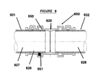
- FIG. 9 provides a schematic, longitudinal cross-sectional view of pipe connection assembly 600 , the assembly containing and connecting between a first pipe 927 having an outer (typically cylindrical) surface 931 and a second pipe 928 having an outer (typically cylindrical) surface 932 .
- a recess 650 in housing 620 may be adapted to include or secure a sealing element 651 such as an O-ring, which may tightly fit around surface 931 of pipe 927 , whereby sealing is effected between surface 931 and terminal surface 626 of housing 620 .
- a sealing element 651 such as an O-ring
- FIG. 10A provides a transverse cross-sectional view of FIG. 9 , in which lock pin 860 is partially inserted in open-ended (lock-pin) channel 630 . Initially, the insertion of lock pin 860 may proceed with facility and with little mechanical resistance. As the position of lock pin 860 proceeds longitudinally through channel 630 , bottom edge 865 of tooth 864 will eventually contact outer surface 931 of pipe 927 .
- lock pin 860 may be driven (e.g., by hammering) or pulled (e.g., as described hereinabove) through channel 630 .
- Bottom edge 865 of tooth 864 impinges upon outer surface 931 of pipe 927 , and may even deform outer surface 931 , to secure pipe 927 within pipe connection assembly 600 , as shown in FIG. 10B .
- FIG. 11 provides a schematic, longitudinal cross-sectional view of a pipe connection assembly 1100 according to one embodiment of the present invention, in which the assembly is a three-way pipe adaptor.
- FIG. 12 provides a schematic, longitudinal cross-sectional view of a pipe connection assembly 1200 according to one embodiment of the present invention, in which the assembly is an end seal or fitting.
- FIG. 13 provides a schematic, longitudinal cross-sectional view of a pipe connection assembly 1300 according to one embodiment of the present invention, in which one end of the assembly is a sprinkler fitting 1385 .
- FIG. 14 provides a schematic, longitudinal cross-sectional view of a pipe connection assembly 1400 according to one embodiment of the present invention, in which the assembly is a three-way pipe adaptor having a sprinkler fitting 1485 .
- FIG. 15A provides a partial, schematic, longitudinal cross-sectional view of a pipe connector, according to one embodiment of the present invention.
- FIG. 15B provides a schematic, transverse cross-sectional view of the pipe connector shown in FIG. 15A .
- the pin backbone has a longitudinal length L, and at least a portion of a perimeter of the backbone has a screw contour along at least 50%, at least 70%, at least 80%, at least 90%, at least 95%, or along all of length L.
- the backbone has a screw contour along the entire length L.
- the backbone may have, over at least a portion of a longitudinal length L 1 between the lead end and the tooth, a screw contour around an entire perimeter of the backbone.
- the entire perimeter of the backbone has a screw contour over the entire longitudinal length L 1 between the lead end and the tooth.
- FIG. 16 provides a partial, schematic, longitudinal cross-sectional view of a pipe connection assembly having a lip seal recess 1650 adapted to include or secure a sealing element 1651 such as a lip seal 1651 , according to one embodiment of the present invention.
Landscapes
- Engineering & Computer Science (AREA)
- General Engineering & Computer Science (AREA)
- Mechanical Engineering (AREA)
- Health & Medical Sciences (AREA)
- Public Health (AREA)
- Business, Economics & Management (AREA)
- Emergency Management (AREA)
- Quick-Acting Or Multi-Walled Pipe Joints (AREA)
- Mutual Connection Of Rods And Tubes (AREA)
- Joints With Sleeves (AREA)
Applications Claiming Priority (3)
| Application Number | Priority Date | Filing Date | Title |
|---|---|---|---|
| GB1209568.3A GB2502545B (en) | 2012-05-30 | 2012-05-30 | Pipe fitting |
| GB1209568.3 | 2012-05-30 | ||
| PCT/IB2013/001114 WO2013179127A1 (en) | 2012-05-30 | 2013-05-30 | Pipe fitting |
Related Parent Applications (1)
| Application Number | Title | Priority Date | Filing Date |
|---|---|---|---|
| PCT/IB2013/001114 A-371-Of-International WO2013179127A1 (en) | 2012-05-30 | 2013-05-30 | Pipe fitting |
Related Child Applications (1)
| Application Number | Title | Priority Date | Filing Date |
|---|---|---|---|
| US15/856,177 Continuation US20180180202A1 (en) | 2012-05-30 | 2017-12-28 | Pipe fitting |
Publications (2)
| Publication Number | Publication Date |
|---|---|
| US20150330543A1 US20150330543A1 (en) | 2015-11-19 |
| US9890881B2 true US9890881B2 (en) | 2018-02-13 |
Family
ID=46546155
Family Applications (2)
| Application Number | Title | Priority Date | Filing Date |
|---|---|---|---|
| US14/404,472 Expired - Fee Related US9890881B2 (en) | 2012-05-30 | 2013-05-30 | Pipe fitting |
| US15/856,177 Abandoned US20180180202A1 (en) | 2012-05-30 | 2017-12-28 | Pipe fitting |
Family Applications After (1)
| Application Number | Title | Priority Date | Filing Date |
|---|---|---|---|
| US15/856,177 Abandoned US20180180202A1 (en) | 2012-05-30 | 2017-12-28 | Pipe fitting |
Country Status (18)
| Country | Link |
|---|---|
| US (2) | US9890881B2 (enExample) |
| EP (1) | EP2855996B1 (enExample) |
| JP (1) | JP6101796B2 (enExample) |
| KR (1) | KR20150021084A (enExample) |
| CN (1) | CN104487752B (enExample) |
| AU (1) | AU2013269253B2 (enExample) |
| BR (1) | BR112014029893A2 (enExample) |
| DK (1) | DK2855996T3 (enExample) |
| ES (1) | ES2651589T3 (enExample) |
| GB (1) | GB2502545B (enExample) |
| HU (1) | HUE037696T2 (enExample) |
| IL (1) | IL235971A0 (enExample) |
| MX (1) | MX2014014553A (enExample) |
| NO (1) | NO2855996T3 (enExample) |
| PL (1) | PL2855996T3 (enExample) |
| RU (1) | RU2621429C2 (enExample) |
| SI (1) | SI2855996T1 (enExample) |
| WO (1) | WO2013179127A1 (enExample) |
Families Citing this family (2)
| Publication number | Priority date | Publication date | Assignee | Title |
|---|---|---|---|---|
| FR3048050B1 (fr) * | 2016-02-23 | 2018-08-17 | Robert Bandera | Dispositif de raccordement pour la connexion d'un tube |
| CN108895221A (zh) * | 2018-09-04 | 2018-11-27 | 宝鸡市创信金属材料有限公司 | 一种用于石油管道的快速装夹稳流锁紧连接段 |
Citations (16)
| Publication number | Priority date | Publication date | Assignee | Title |
|---|---|---|---|---|
| GB631745A (en) | 1946-12-11 | 1949-11-09 | Ernest William Poole Lines | An improved tube joint |
| US4289339A (en) * | 1979-11-28 | 1981-09-15 | Meyertech Incorporated | Fitting with tangential locking rod for coupling pipes |
| EP0054173A1 (de) | 1980-12-11 | 1982-06-23 | Georg Fischer Aktiengesellschaft | Lösbare Rohrverbindung |
| EP0070561A2 (de) | 1981-07-22 | 1983-01-26 | Georg Fischer Aktiengesellschaft | Vorrichtung zum festen flüssigkeits- und gasdichten Verbinden von zwei Rohren |
| US4401324A (en) * | 1981-02-19 | 1983-08-30 | Michigan Pipe Fittings Co. Div. Of Michigan Hanger Co. | Pipe coupling with a locking device |
| US4701074A (en) * | 1986-04-17 | 1987-10-20 | Wimpey Laboratories Limited | Apparatus for forming a grouted member in deep water |
| US5040831A (en) | 1990-01-12 | 1991-08-20 | Phil Lewis | Non threaded pipe connector system |
| CN2120244U (zh) | 1992-04-07 | 1992-10-28 | 杨明东 | 管件快速接头 |
| US5281005A (en) * | 1992-07-31 | 1994-01-25 | Dana Corporation | Spindle retainer for axle housing |
| CN1163367A (zh) | 1996-04-19 | 1997-10-29 | 株式会社竹中工务店 | 管道接头装置 |
| US5779283A (en) | 1996-04-10 | 1998-07-14 | Takenaka Corporation | Pipe joint unit |
| US5927763A (en) | 1997-09-19 | 1999-07-27 | Mehr; Ralph R. | Pipe connections and methods for connecting pipes |
| EP1024324A2 (en) * | 1999-01-29 | 2000-08-02 | Renato Colombo | Device for mutually coupling the body of a valve element or the like and a connecting element |
| US7168451B1 (en) * | 2006-02-06 | 2007-01-30 | Dundas Robert D | Removable hose cover |
| EP1882877A2 (en) | 2006-07-24 | 2008-01-30 | Renato Colombo | Device for quick connection of two components of systems for the distribution of liquids or gases, with high safety against tampering |
| CN202165735U (zh) | 2011-07-27 | 2012-03-14 | 深圳路升光电科技有限公司 | 管连接结构 |
Family Cites Families (6)
| Publication number | Priority date | Publication date | Assignee | Title |
|---|---|---|---|---|
| JPS505059Y1 (enExample) * | 1970-12-22 | 1975-02-12 | ||
| DE2202808A1 (de) * | 1972-01-21 | 1973-08-02 | Welcker F | Verfahren zur herstellung von rohrleitungsanschluessen |
| JPS5758920U (enExample) * | 1980-09-20 | 1982-04-07 | ||
| JPS6396389A (ja) * | 1986-10-14 | 1988-04-27 | 日東工器株式会社 | 管継手 |
| JPH08121662A (ja) * | 1994-10-19 | 1996-05-17 | Takenaka Komuten Co Ltd | 配管継手装置 |
| DE102006038841A1 (de) * | 2006-08-18 | 2008-02-21 | Robert Bosch Gmbh | Vorrichtung zur axialen Verbindung eines äusseren Rohrteils mit einem in das Rohrteil eingreifenden koaxialen Zapfenteil oder inneren Rohrteil |
-
2012
- 2012-05-30 GB GB1209568.3A patent/GB2502545B/en not_active Expired - Fee Related
-
2013
- 2013-05-30 AU AU2013269253A patent/AU2013269253B2/en not_active Ceased
- 2013-05-30 JP JP2015514611A patent/JP6101796B2/ja not_active Expired - Fee Related
- 2013-05-30 EP EP13747495.3A patent/EP2855996B1/en not_active Not-in-force
- 2013-05-30 BR BR112014029893A patent/BR112014029893A2/pt not_active IP Right Cessation
- 2013-05-30 HU HUE13747495A patent/HUE037696T2/hu unknown
- 2013-05-30 PL PL13747495T patent/PL2855996T3/pl unknown
- 2013-05-30 ES ES13747495.3T patent/ES2651589T3/es active Active
- 2013-05-30 KR KR1020147036827A patent/KR20150021084A/ko not_active Withdrawn
- 2013-05-30 DK DK13747495.3T patent/DK2855996T3/en active
- 2013-05-30 WO PCT/IB2013/001114 patent/WO2013179127A1/en not_active Ceased
- 2013-05-30 US US14/404,472 patent/US9890881B2/en not_active Expired - Fee Related
- 2013-05-30 MX MX2014014553A patent/MX2014014553A/es unknown
- 2013-05-30 NO NO13747495A patent/NO2855996T3/no unknown
- 2013-05-30 SI SI201330882T patent/SI2855996T1/en unknown
- 2013-05-30 CN CN201380038798.2A patent/CN104487752B/zh not_active Expired - Fee Related
- 2013-05-30 RU RU2014152887A patent/RU2621429C2/ru not_active IP Right Cessation
-
2014
- 2014-11-27 IL IL235971A patent/IL235971A0/en unknown
-
2017
- 2017-12-28 US US15/856,177 patent/US20180180202A1/en not_active Abandoned
Patent Citations (17)
| Publication number | Priority date | Publication date | Assignee | Title |
|---|---|---|---|---|
| GB631745A (en) | 1946-12-11 | 1949-11-09 | Ernest William Poole Lines | An improved tube joint |
| US4289339A (en) * | 1979-11-28 | 1981-09-15 | Meyertech Incorporated | Fitting with tangential locking rod for coupling pipes |
| EP0054173A1 (de) | 1980-12-11 | 1982-06-23 | Georg Fischer Aktiengesellschaft | Lösbare Rohrverbindung |
| US4401324A (en) * | 1981-02-19 | 1983-08-30 | Michigan Pipe Fittings Co. Div. Of Michigan Hanger Co. | Pipe coupling with a locking device |
| EP0070561A2 (de) | 1981-07-22 | 1983-01-26 | Georg Fischer Aktiengesellschaft | Vorrichtung zum festen flüssigkeits- und gasdichten Verbinden von zwei Rohren |
| US4701074A (en) * | 1986-04-17 | 1987-10-20 | Wimpey Laboratories Limited | Apparatus for forming a grouted member in deep water |
| US5040831A (en) | 1990-01-12 | 1991-08-20 | Phil Lewis | Non threaded pipe connector system |
| CN2120244U (zh) | 1992-04-07 | 1992-10-28 | 杨明东 | 管件快速接头 |
| US5281005A (en) * | 1992-07-31 | 1994-01-25 | Dana Corporation | Spindle retainer for axle housing |
| US5779283A (en) | 1996-04-10 | 1998-07-14 | Takenaka Corporation | Pipe joint unit |
| CN1163367A (zh) | 1996-04-19 | 1997-10-29 | 株式会社竹中工务店 | 管道接头装置 |
| US5927763A (en) | 1997-09-19 | 1999-07-27 | Mehr; Ralph R. | Pipe connections and methods for connecting pipes |
| US6634677B2 (en) | 1997-09-19 | 2003-10-21 | Ralph R. Mehr | Pipe connections and methods for connecting pipes |
| EP1024324A2 (en) * | 1999-01-29 | 2000-08-02 | Renato Colombo | Device for mutually coupling the body of a valve element or the like and a connecting element |
| US7168451B1 (en) * | 2006-02-06 | 2007-01-30 | Dundas Robert D | Removable hose cover |
| EP1882877A2 (en) | 2006-07-24 | 2008-01-30 | Renato Colombo | Device for quick connection of two components of systems for the distribution of liquids or gases, with high safety against tampering |
| CN202165735U (zh) | 2011-07-27 | 2012-03-14 | 深圳路升光电科技有限公司 | 管连接结构 |
Non-Patent Citations (15)
| Title |
|---|
| Australian Examiner's Report for AU 2013269253, report dated Sep. 13, 2016. |
| Chinese Search Report for CN 2013800387982, search report dated May 30, 2013. |
| International Search Report for PCT/IB2013/001114, search report dated Oct. 29, 2013. |
| Machine Translation of CN 1163367 (by EPO and Google)-published Oct. 29, 1997 Takenaka. |
| Machine Translation of CN 1163367 (by EPO and Google)—published Oct. 29, 1997 Takenaka. |
| Machine Translation of CN 202165735 (by EPO and Google)-published Mar. 14, 2012 Shenzhen Luxon Optoelectronics Technology Co Ltd. |
| Machine Translation of CN 202165735 (by EPO and Google)—published Mar. 14, 2012 Shenzhen Luxon Optoelectronics Technology Co Ltd. |
| Machine Translation of CN 2120244 (by EPO and Google)-published Oct. 28, 1992 Yang Mingdong. |
| Machine Translation of CN 2120244 (by EPO and Google)—published Oct. 28, 1992 Yang Mingdong. |
| Machine Translation of EP 0054173 (by EPO and Google)-published Jun. 23, 1982 Fischer Ag Georg. |
| Machine Translation of EP 0054173 (by EPO and Google)—published Jun. 23, 1982 Fischer Ag Georg. |
| Machine Translation of EP 0070561 (by EPO and Google)-published Jan. 26, 1983 Fischer Ag Georg. |
| Machine Translation of EP 0070561 (by EPO and Google)—published Jan. 26, 1983 Fischer Ag Georg. |
| UKIPO Search Report for GB1209568.3, report dated Aug. 25, 2012. |
| Written Opinion for PCT/IB2013/001114, written opinion dated Oct. 29, 2013. |
Also Published As
| Publication number | Publication date |
|---|---|
| GB201209568D0 (en) | 2012-07-11 |
| PL2855996T3 (pl) | 2018-03-30 |
| JP6101796B2 (ja) | 2017-03-22 |
| MX2014014553A (es) | 2015-05-11 |
| CN104487752A (zh) | 2015-04-01 |
| ES2651589T3 (es) | 2018-01-29 |
| US20150330543A1 (en) | 2015-11-19 |
| NO2855996T3 (enExample) | 2018-02-10 |
| EP2855996A1 (en) | 2015-04-08 |
| BR112014029893A2 (pt) | 2017-07-25 |
| RU2014152887A (ru) | 2016-07-20 |
| HUE037696T2 (hu) | 2018-09-28 |
| US20180180202A1 (en) | 2018-06-28 |
| EP2855996B1 (en) | 2017-09-13 |
| DK2855996T3 (en) | 2018-01-02 |
| CN104487752B (zh) | 2016-10-05 |
| JP2015523510A (ja) | 2015-08-13 |
| GB2502545A (en) | 2013-12-04 |
| GB2502545B (en) | 2014-09-17 |
| AU2013269253A1 (en) | 2015-01-22 |
| WO2013179127A1 (en) | 2013-12-05 |
| KR20150021084A (ko) | 2015-02-27 |
| SI2855996T1 (en) | 2018-02-28 |
| AU2013269253B2 (en) | 2017-09-07 |
| IL235971A0 (en) | 2015-01-29 |
| RU2621429C2 (ru) | 2017-06-06 |
Similar Documents
| Publication | Publication Date | Title |
|---|---|---|
| US10174873B2 (en) | Extraction device for removing an adapter secured in a port | |
| US9458610B2 (en) | Plumbing connector | |
| US6634677B2 (en) | Pipe connections and methods for connecting pipes | |
| CN102066822A (zh) | 机械管道装配装置 | |
| CN105339715B (zh) | 管道连接件 | |
| US20130154260A1 (en) | Coupling And Joint For Fixedly And Sealingly Securing Components To One Another | |
| US20180180202A1 (en) | Pipe fitting | |
| KR101267647B1 (ko) | 플라스틱수지 파이프용의 관이음매 | |
| US20030197378A1 (en) | Sealing compression ferrule for plumbing connection fitting | |
| KR101676320B1 (ko) | 파이프 연결구의 구조 | |
| KR20160095571A (ko) | 파이프 연결구의 구조 | |
| CN207049478U (zh) | 水管连接器 | |
| KR200448977Y1 (ko) | 배관 연결구 | |
| EP3021028B1 (en) | Pipe clamp assembly with stiffening element | |
| JP2007138980A (ja) | 管継手 | |
| JP2007198542A (ja) | 管継手 | |
| KR100943787B1 (ko) | 슬라이드 조임식 파이프 연결 소켓 | |
| KR200439127Y1 (ko) | 배관 조인트용 체결 압착 홀더 | |
| JP2014121107A (ja) | ネジ無し電線管用継手 | |
| JP2007205461A (ja) | 管継手 | |
| JP2008082373A (ja) | 食い込み式管継手、冷凍装置及び温水装置 | |
| JP2011007205A (ja) | 離脱防止管継手 | |
| JP2003254476A (ja) | メカニカル式管継手 | |
| JP2005155828A (ja) | 柔軟管継手方法と継手コネクタ及びかしめ加工工具 |
Legal Events
| Date | Code | Title | Description |
|---|---|---|---|
| STCF | Information on status: patent grant |
Free format text: PATENTED CASE |
|
| FEPP | Fee payment procedure |
Free format text: MAINTENANCE FEE REMINDER MAILED (ORIGINAL EVENT CODE: REM.); ENTITY STATUS OF PATENT OWNER: SMALL ENTITY |
|
| LAPS | Lapse for failure to pay maintenance fees |
Free format text: PATENT EXPIRED FOR FAILURE TO PAY MAINTENANCE FEES (ORIGINAL EVENT CODE: EXP.); ENTITY STATUS OF PATENT OWNER: SMALL ENTITY |
|
| STCH | Information on status: patent discontinuation |
Free format text: PATENT EXPIRED DUE TO NONPAYMENT OF MAINTENANCE FEES UNDER 37 CFR 1.362 |
|
| FP | Lapsed due to failure to pay maintenance fee |
Effective date: 20220213 |