US4701074A - Apparatus for forming a grouted member in deep water - Google Patents
Apparatus for forming a grouted member in deep water Download PDFInfo
- Publication number
- US4701074A US4701074A US06/852,999 US85299986A US4701074A US 4701074 A US4701074 A US 4701074A US 85299986 A US85299986 A US 85299986A US 4701074 A US4701074 A US 4701074A
- Authority
- US
- United States
- Prior art keywords
- coupling member
- male
- female coupling
- female
- pin
- Prior art date
- Legal status (The legal status is an assumption and is not a legal conclusion. Google has not performed a legal analysis and makes no representation as to the accuracy of the status listed.)
- Expired - Fee Related
Links
- XLYOFNOQVPJJNP-UHFFFAOYSA-N water Substances O XLYOFNOQVPJJNP-UHFFFAOYSA-N 0.000 title claims abstract description 9
- 230000008878 coupling Effects 0.000 claims abstract description 79
- 238000010168 coupling process Methods 0.000 claims abstract description 79
- 238000005859 coupling reaction Methods 0.000 claims abstract description 79
- 239000000463 material Substances 0.000 claims abstract description 17
- 238000007789 sealing Methods 0.000 claims description 7
- 230000037431 insertion Effects 0.000 claims description 4
- 238000003780 insertion Methods 0.000 claims description 4
- 239000011440 grout Substances 0.000 description 2
- 238000004140 cleaning Methods 0.000 description 1
- 230000000295 complement effect Effects 0.000 description 1
- 238000010586 diagram Methods 0.000 description 1
- 238000009434 installation Methods 0.000 description 1
- 230000007935 neutral effect Effects 0.000 description 1
- 230000032258 transport Effects 0.000 description 1
Images


Classifications
-
- E—FIXED CONSTRUCTIONS
- E02—HYDRAULIC ENGINEERING; FOUNDATIONS; SOIL SHIFTING
- E02B—HYDRAULIC ENGINEERING
- E02B17/00—Artificial islands mounted on piles or like supports, e.g. platforms on raisable legs or offshore constructions; Construction methods therefor
- E02B17/0008—Methods for grouting offshore structures; apparatus therefor
-
- F—MECHANICAL ENGINEERING; LIGHTING; HEATING; WEAPONS; BLASTING
- F16—ENGINEERING ELEMENTS AND UNITS; GENERAL MEASURES FOR PRODUCING AND MAINTAINING EFFECTIVE FUNCTIONING OF MACHINES OR INSTALLATIONS; THERMAL INSULATION IN GENERAL
- F16B—DEVICES FOR FASTENING OR SECURING CONSTRUCTIONAL ELEMENTS OR MACHINE PARTS TOGETHER, e.g. NAILS, BOLTS, CIRCLIPS, CLAMPS, CLIPS OR WEDGES; JOINTS OR JOINTING
- F16B3/00—Key-type connections; Keys
-
- F—MECHANICAL ENGINEERING; LIGHTING; HEATING; WEAPONS; BLASTING
- F16—ENGINEERING ELEMENTS AND UNITS; GENERAL MEASURES FOR PRODUCING AND MAINTAINING EFFECTIVE FUNCTIONING OF MACHINES OR INSTALLATIONS; THERMAL INSULATION IN GENERAL
- F16L—PIPES; JOINTS OR FITTINGS FOR PIPES; SUPPORTS FOR PIPES, CABLES OR PROTECTIVE TUBING; MEANS FOR THERMAL INSULATION IN GENERAL
- F16L37/00—Couplings of the quick-acting type
- F16L37/002—Couplings of the quick-acting type which can be controlled at a distance
-
- F—MECHANICAL ENGINEERING; LIGHTING; HEATING; WEAPONS; BLASTING
- F16—ENGINEERING ELEMENTS AND UNITS; GENERAL MEASURES FOR PRODUCING AND MAINTAINING EFFECTIVE FUNCTIONING OF MACHINES OR INSTALLATIONS; THERMAL INSULATION IN GENERAL
- F16L—PIPES; JOINTS OR FITTINGS FOR PIPES; SUPPORTS FOR PIPES, CABLES OR PROTECTIVE TUBING; MEANS FOR THERMAL INSULATION IN GENERAL
- F16L37/00—Couplings of the quick-acting type
- F16L37/08—Couplings of the quick-acting type in which the connection between abutting or axially overlapping ends is maintained by locking members
- F16L37/12—Couplings of the quick-acting type in which the connection between abutting or axially overlapping ends is maintained by locking members using hooks, pawls or other movable or insertable locking members
- F16L37/14—Joints secured by inserting between mating surfaces an element, e.g. a piece of wire, a pin, a chain
- F16L37/142—Joints secured by inserting between mating surfaces an element, e.g. a piece of wire, a pin, a chain where the securing element is inserted tangentially
- F16L37/146—Joints secured by inserting between mating surfaces an element, e.g. a piece of wire, a pin, a chain where the securing element is inserted tangentially the securing element being a rigid pin, screw or the like
-
- Y—GENERAL TAGGING OF NEW TECHNOLOGICAL DEVELOPMENTS; GENERAL TAGGING OF CROSS-SECTIONAL TECHNOLOGIES SPANNING OVER SEVERAL SECTIONS OF THE IPC; TECHNICAL SUBJECTS COVERED BY FORMER USPC CROSS-REFERENCE ART COLLECTIONS [XRACs] AND DIGESTS
- Y10—TECHNICAL SUBJECTS COVERED BY FORMER USPC
- Y10S—TECHNICAL SUBJECTS COVERED BY FORMER USPC CROSS-REFERENCE ART COLLECTIONS [XRACs] AND DIGESTS
- Y10S285/00—Pipe joints or couplings
- Y10S285/92—Remotely controlled
-
- Y—GENERAL TAGGING OF NEW TECHNOLOGICAL DEVELOPMENTS; GENERAL TAGGING OF CROSS-SECTIONAL TECHNOLOGIES SPANNING OVER SEVERAL SECTIONS OF THE IPC; TECHNICAL SUBJECTS COVERED BY FORMER USPC CROSS-REFERENCE ART COLLECTIONS [XRACs] AND DIGESTS
- Y10—TECHNICAL SUBJECTS COVERED BY FORMER USPC
- Y10T—TECHNICAL SUBJECTS COVERED BY FORMER US CLASSIFICATION
- Y10T403/00—Joints and connections
- Y10T403/59—Manually releaseable latch type
- Y10T403/597—Swiveled bolt
-
- Y—GENERAL TAGGING OF NEW TECHNOLOGICAL DEVELOPMENTS; GENERAL TAGGING OF CROSS-SECTIONAL TECHNOLOGIES SPANNING OVER SEVERAL SECTIONS OF THE IPC; TECHNICAL SUBJECTS COVERED BY FORMER USPC CROSS-REFERENCE ART COLLECTIONS [XRACs] AND DIGESTS
- Y10—TECHNICAL SUBJECTS COVERED BY FORMER USPC
- Y10T—TECHNICAL SUBJECTS COVERED BY FORMER US CLASSIFICATION
- Y10T403/00—Joints and connections
- Y10T403/59—Manually releaseable latch type
- Y10T403/598—Transversely sliding pin
Definitions
- This invention relates to apparatus for forming grouted members in deep water.
- Platforms are located in deep water by means of piles driven into the seabed and fixed to legs of the platform. These piles are surrounded by sleeves which are filled with grouting material.
- piles are surrounded by sleeves which are filled with grouting material.
- pipework extends from the deck of the platform along the length of each leg of the platform, and grouting material is forced along this pipework to the respective sleeves. Once the pile has been grouted in place, this pipework is redundant. However, the cost of installing the pipework on the platform is quite considerable.
- the present invention therefore seeks to provide an apparatus for forming grouted members, e.g. piles, in deep water, where the permanent installation of expensive pipework to the surface is not required.
- an apparatus for forming a grouted member in deep water comprising: a female coupling member for connection to a male coupling member located on the seabed; guide means for guiding the male coupling member into engagement with the female coupling member; locking means, operable by a remotely operated underwater vehicle, for retaining the male coupling member in engagement with the female coupling member; and means for connecting the female coupling member to a source of grouting material.
- the locking means comprises a pin rotatably mounted in the coupling member, the pin having a recess which, in an unlocked position, permits the insertion of the male coupling member into the female coupling member and in a locked position, engages in a groove in the male coupling member to retain the male coupling member in engagement with the female coupling member.
- the apparatus may include means for limiting rotation of the pin.
- the apparatus preferably includes further guide means for guiding an operating member of the underwater vehicle into engagement with the locking means.
- the apparatus includes valve means for controlling flow of grouting material to the female coupling member.
- the apparatus may include operating means, operable by the underwater vehicle, for moving the valve means between open and closed positions. Means may be provided for limiting rotation of the operating means.
- the apparatus may include guide means for guiding an operating member of the underwater vehicle into engagement with the operating means.
- the apparatus is preferably in combination with the male coupling member.
- the apparatus preferably includes sealing means on the male coupling member for effecting a seal between the female coupling member and the male coupling member when the latter is inserted into the former.
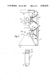
- FIG. 1 is a schematic diagram, partially broken away, of an apparatus according to the present invention for grouting piles in deep water;
- FIG. 2 is a cross-section of male and female coupling members of the apparatus of FIG. 1;
- FIG. 3 is a section taken along the line 3--3 of FIG. 2.
- FIG. 1 there is shown a preferred embodiment of an apparatus 10 according to the present invention for grouting piles of a platform in deep water.
- the apparatus is operated by a conventional remotely operated underwater vehicle (not shown) which is controlled by an operator, for example, on a deck of the platform.
- a male coupling member 11 is connected to a grout pipe 12 through which grout is supplied to a jacket or sleeve (not shown) surrounding a pile to be grouted.
- the male coupling member is fixed to the pipe 12 and is, therefore, permanently installed on the sea bed.
- the male coupling member 11 is cylindrical and has an annular locking pin groove 13 and a sealing member 14 (best seen in FIG. 2) having a U-shaped cross-section.
- the apparatus 10 has a male coupling cone 15 for guiding the male coupling member 11 towards a female coupling member 16.
- the cone 15 has fixed thereto at least one handle 17.
- An arm (not shown) of the underwater vehicle engages the handle 17 and transports the apparatus 10 until the cone 15 is positioned substantially centrally over the male coupling member 11. The apparatus 10 is then lowered onto the male coupling member, the cone 15 guiding the male coupling member towards the female coupling member 16.
- the female coupling member 16 has a first conical inner surface 18 which forms a smooth continuation of the inner wall of the cone 15, a substantially cylindrical inner surface 19, a further conical surface 20 with a smaller cone angle than the conical surface 18 and a cylindrical conduit 21.
- the male coupling member 11 is guided by the cone 15 and the conical surface 18 of the female coupling member 16 so that when fully inserted into the female coupling member, a head 22 of the male coupling member seats against the surface 20 compressing the sealing member 14.
- the conical surface 20 and the surface of the head 22 of the male coupling member are complementary so that the sealing member 14 forms an effective seal between the two.
- the insertion of the male coupling member 11 into the female coupling member 16 is limited by an annular ledge 23.
- the ledge 23 is so disposed to prevent the male coupling member 11 from becoming wedged in the female coupling member 16 whilst still allowing the sealing member 14 to form an effective seal.
- the locking pin passes through a passageway 25 in the female coupling member and is free to rotate therein.
- the locking pin 24 has an enlarged diameter cylindrical portion 27 and a reduced diameter cylindrical portion 28.
- a ledge 29 between the portions 27,28 rests on a surface 30 of a cut-away portion 31 of the female coupling member thus limiting axial insertion of the locking pin 24 into the passageway 25.
- a bushing 26 seats on a surface 32 of a cut-away portion 33 of the female coupling member and the bushing is connected to the locking pin 24 by means of a split pin 34.
- the locking pin 24 has a recess 35 which, when the locking pin 24 is in unlocked position forms a continuation of the cylindrical surface 19 of the female coupling member 16. Thus the male coupling member 11 can be fully inserted into the female coupling member 16.
- a portion 36 of the locking pin 24 enters the groove 13 in the male coupling member 11 thus preventing it from being removed from the female coupling member.
- the locking pin 24 carries a trapezoidal plate member 37 (FIG. 1) which, in operation, connects with an operating member of the underwater vehicle to be rotated thereby.
- the plate member 37 is surrounded by a conical housing 38 fixed to the female coupling member via a cylindrical neck 40.
- the purpose of the housing 38 is to guide the operating member of the underwater vehicle towards the plate member 37.
- a slot 39 is cut in the neck 40 and an abutment pin 41 extends through this slot and is fixed to the locking pin 24.
- the slot 39 limits rotation of the locking pin 24 and its ends define the locked and unlocked positions.
- the abutment pin 41 can be removed from the locking pin 24 to enable the latter to be removed from the passageway 25 as discussed above.
- the abutment pin 41 may be screw-threaded into an appropriate aperture or hole in the locking pin 24.
- the conduit 21 is connected to a valve 42.
- the valve 42 has a hollow rectangular stem 43 to the free end of which there is fixed a trapezoidal plate member 44, similar to the plate member 37.
- the plate member 44 is surrounded by a conical housing 45 connected to the valve 42 by a cylindrical neck 46.
- the purpose of the housing 45 is to guide the operating member of the underwater vehicle towards the plate member 44.
- a slot 47 extending over 90°, is cut in the neck 46, and an abutment pin 48 extends through this slot and is fixed to the stem 43.
- the slot 47 limits rotation of the pin 48 and its ends define open and closed positions of the valve 42.
- the valve 42 may be of any known type, for example, a butterfly valve.
- the operating member of the underwater vehicle connects to the plate member 44 and is rotated through 90° so that the valve 42 is moved between open and closed positions.
- the valve 42 thus controls the flow of grouting material from a conduit 49 to the conduit 21.
- the conduit 49 is connected to a pipeline 50 which connects the apparatus 10 to a source (not shown) of grouting material under pressure, e.g. 70 kg/cm 2 (1000 psi) located, for example, on the deck of the platform.
- a source not shown
- At least a part of the pipeline 50 is surrounded by a buoyancy device 51 so that the pipeline 50 has either neutral or slightly negative buoyancy when there is no grouting material therein.
- a buoyancy device 51 so that the pipeline 50 has either neutral or slightly negative buoyancy when there is no grouting material therein.
- the underwater vehicle In order to fill a sleeve surrounding a pile on the sea bed with grouting material, the underwater vehicle carries the apparatus 10, after having been connected to the pipeline 50, so that it is positioned substantially over the male coupling member 11. The underwater vehicle then lowers the apparatus 10, and the male coupling member is guided into the female coupling member 16.
- an operating member on the underwater vehicle engages a plate 37 and rotates it through 180° whereby the locking pin 24 engages in the groove 13 of the male coupling member 11 locking it to the female coupling member.
- the operating member on the underwater vehicle then engages the plate member 44 and rotates it through 90°, thereby moving the valve 42 to the open position so that grouting material can pass through the apparatus 10 to the sleeve to be grouted.
Abstract
Apparatus for forming a grouting member, for example, a grouted pile, in deep water comprises a female coupling member for connection to a male coupling member located on the sea bed, a conical guide for guiding the male coupling member into engagement with the female coupling member, a rotatable locking pin having an arcute recess portion, operable by a remotely operated underwater vehicle, for retaining the male coupling member in engagement with the female coupling member, and a connector for connecting the female coupling member to a source of grouting material.
Description
This invention relates to apparatus for forming grouted members in deep water.
Platforms are located in deep water by means of piles driven into the seabed and fixed to legs of the platform. These piles are surrounded by sleeves which are filled with grouting material. Conventionally, pipework extends from the deck of the platform along the length of each leg of the platform, and grouting material is forced along this pipework to the respective sleeves. Once the pile has been grouted in place, this pipework is redundant. However, the cost of installing the pipework on the platform is quite considerable.
The present invention therefore seeks to provide an apparatus for forming grouted members, e.g. piles, in deep water, where the permanent installation of expensive pipework to the surface is not required.
According to the present invention there is provided an apparatus for forming a grouted member in deep water comprising: a female coupling member for connection to a male coupling member located on the seabed; guide means for guiding the male coupling member into engagement with the female coupling member; locking means, operable by a remotely operated underwater vehicle, for retaining the male coupling member in engagement with the female coupling member; and means for connecting the female coupling member to a source of grouting material.
Preferably the locking means comprises a pin rotatably mounted in the coupling member, the pin having a recess which, in an unlocked position, permits the insertion of the male coupling member into the female coupling member and in a locked position, engages in a groove in the male coupling member to retain the male coupling member in engagement with the female coupling member.
The apparatus may include means for limiting rotation of the pin.
The apparatus preferably includes further guide means for guiding an operating member of the underwater vehicle into engagement with the locking means.
In the preferred embodiment the apparatus includes valve means for controlling flow of grouting material to the female coupling member. The apparatus may include operating means, operable by the underwater vehicle, for moving the valve means between open and closed positions. Means may be provided for limiting rotation of the operating means.
The apparatus may include guide means for guiding an operating member of the underwater vehicle into engagement with the operating means.
The apparatus is preferably in combination with the male coupling member. Thus the apparatus preferably includes sealing means on the male coupling member for effecting a seal between the female coupling member and the male coupling member when the latter is inserted into the former.
The invention is illustrated, merely by way of example, in the accompanying drawings, in which:
FIG. 1 is a schematic diagram, partially broken away, of an apparatus according to the present invention for grouting piles in deep water;
FIG. 2 is a cross-section of male and female coupling members of the apparatus of FIG. 1; and
FIG. 3 is a section taken along the line 3--3 of FIG. 2.
Referring to FIG. 1 there is shown a preferred embodiment of an apparatus 10 according to the present invention for grouting piles of a platform in deep water. The apparatus is operated by a conventional remotely operated underwater vehicle (not shown) which is controlled by an operator, for example, on a deck of the platform.
A male coupling member 11 is connected to a grout pipe 12 through which grout is supplied to a jacket or sleeve (not shown) surrounding a pile to be grouted. The male coupling member is fixed to the pipe 12 and is, therefore, permanently installed on the sea bed. The male coupling member 11 is cylindrical and has an annular locking pin groove 13 and a sealing member 14 (best seen in FIG. 2) having a U-shaped cross-section.
The apparatus 10 has a male coupling cone 15 for guiding the male coupling member 11 towards a female coupling member 16. The cone 15 has fixed thereto at least one handle 17. An arm (not shown) of the underwater vehicle engages the handle 17 and transports the apparatus 10 until the cone 15 is positioned substantially centrally over the male coupling member 11. The apparatus 10 is then lowered onto the male coupling member, the cone 15 guiding the male coupling member towards the female coupling member 16.
The female coupling member 16, best seen in FIG. 2, has a first conical inner surface 18 which forms a smooth continuation of the inner wall of the cone 15, a substantially cylindrical inner surface 19, a further conical surface 20 with a smaller cone angle than the conical surface 18 and a cylindrical conduit 21. The male coupling member 11 is guided by the cone 15 and the conical surface 18 of the female coupling member 16 so that when fully inserted into the female coupling member, a head 22 of the male coupling member seats against the surface 20 compressing the sealing member 14. It will be appreciated that the conical surface 20 and the surface of the head 22 of the male coupling member are complementary so that the sealing member 14 forms an effective seal between the two. The insertion of the male coupling member 11 into the female coupling member 16 is limited by an annular ledge 23. The ledge 23 is so disposed to prevent the male coupling member 11 from becoming wedged in the female coupling member 16 whilst still allowing the sealing member 14 to form an effective seal.
When the male coupling member 11 is fully inserted into the female coupling member 16 the groove 13 in the former is disposed adjacent to a locking pin 24 best shown in FIG. 3. The locking pin passes through a passageway 25 in the female coupling member and is free to rotate therein. The locking pin 24 has an enlarged diameter cylindrical portion 27 and a reduced diameter cylindrical portion 28. A ledge 29 between the portions 27,28 rests on a surface 30 of a cut-away portion 31 of the female coupling member thus limiting axial insertion of the locking pin 24 into the passageway 25. A bushing 26 seats on a surface 32 of a cut-away portion 33 of the female coupling member and the bushing is connected to the locking pin 24 by means of a split pin 34. Thus the locking pin 24 is axially located in the passageway 25 but can be removed, if necessary, for example, for cleaning or repair, by removing the split pin 34 and the bushing 26 allowing the locking pin 24 to be withdrawn from the passageway 25.
The locking pin 24 has a recess 35 which, when the locking pin 24 is in unlocked position forms a continuation of the cylindrical surface 19 of the female coupling member 16. Thus the male coupling member 11 can be fully inserted into the female coupling member 16. When the locking pin 24 is rotated 180° to a locked position (shown in FIGS. 2 and 3) a portion 36 of the locking pin 24 enters the groove 13 in the male coupling member 11 thus preventing it from being removed from the female coupling member.
The locking pin 24 carries a trapezoidal plate member 37 (FIG. 1) which, in operation, connects with an operating member of the underwater vehicle to be rotated thereby. The plate member 37 is surrounded by a conical housing 38 fixed to the female coupling member via a cylindrical neck 40. The purpose of the housing 38 is to guide the operating member of the underwater vehicle towards the plate member 37. A slot 39, extending over 180°, is cut in the neck 40 and an abutment pin 41 extends through this slot and is fixed to the locking pin 24. Thus the slot 39 limits rotation of the locking pin 24 and its ends define the locked and unlocked positions. It will be appreciated that the abutment pin 41 can be removed from the locking pin 24 to enable the latter to be removed from the passageway 25 as discussed above. Thus, for example, the abutment pin 41 may be screw-threaded into an appropriate aperture or hole in the locking pin 24.
The conduit 21 is connected to a valve 42. The valve 42 has a hollow rectangular stem 43 to the free end of which there is fixed a trapezoidal plate member 44, similar to the plate member 37. The plate member 44 is surrounded by a conical housing 45 connected to the valve 42 by a cylindrical neck 46. The purpose of the housing 45 is to guide the operating member of the underwater vehicle towards the plate member 44. A slot 47, extending over 90°, is cut in the neck 46, and an abutment pin 48 extends through this slot and is fixed to the stem 43. Thus the slot 47 limits rotation of the pin 48 and its ends define open and closed positions of the valve 42. The valve 42 may be of any known type, for example, a butterfly valve.
In operation, the operating member of the underwater vehicle connects to the plate member 44 and is rotated through 90° so that the valve 42 is moved between open and closed positions. The valve 42 thus controls the flow of grouting material from a conduit 49 to the conduit 21. The conduit 49 is connected to a pipeline 50 which connects the apparatus 10 to a source (not shown) of grouting material under pressure, e.g. 70 kg/cm2 (1000 psi) located, for example, on the deck of the platform. At least a part of the pipeline 50 is surrounded by a buoyancy device 51 so that the pipeline 50 has either neutral or slightly negative buoyancy when there is no grouting material therein. Thus there is no necessity to fix the pipeline 50 to legs of the platform.
In operation, in order to fill a sleeve surrounding a pile on the sea bed with grouting material, the underwater vehicle carries the apparatus 10, after having been connected to the pipeline 50, so that it is positioned substantially over the male coupling member 11. The underwater vehicle then lowers the apparatus 10, and the male coupling member is guided into the female coupling member 16. When fully inserted, an operating member on the underwater vehicle engages a plate 37 and rotates it through 180° whereby the locking pin 24 engages in the groove 13 of the male coupling member 11 locking it to the female coupling member. The operating member on the underwater vehicle then engages the plate member 44 and rotates it through 90°, thereby moving the valve 42 to the open position so that grouting material can pass through the apparatus 10 to the sleeve to be grouted.
It will be appreciated that the apparatus according to the present invention and described above removes the necessity for fixed pipework on a platform to supply grouting material to sleeves surrounding piles and thus represents a considerable saving in cost.
Claims (8)
1. Apparatus for forming a grouting member underwater comprising: a female coupling member for connection to a male coupling member located on a bed beneath the water; guide means for guiding the female coupling member into engagement with the male coupling member; remotely operable locking means, for retaining the male coupling member in engagement with the female coupling member; and means for connecting the female coupling member to a source of grouting material, the locking means comprising a pin rotatably mounted in the female coupling member, the pin having a recess which, in an unlocked position, permits axial insertion of the male coupling member into the female coupling member and in a locked position, engages in an annular groove in the male coupling member to retain the male coupling member in engagement with the female coupling member.
2. Apparatus as claimed in claim 1 including means for limiting rotation of the pin.
3. Apparatus as claimed in claims 1 or 3 including further guide means for guiding an operating member into engagement with the locking means.
4. Apparatus as claimed in any one of claims 1 to 3 including valve means for controlling flow of grouting material to the female coupling member.
5. Apparatus as claimed in claim 4 including operating means, for moving the valve means between open and closed positions.
6. Apparatus as claimed in claim 5 including means for limiting movement of the operating means.
7. Apparatus as claimed in claim 6 incuding guide means for guiding an operating member into engagement with the operating means.
8. Apparatus for forming a grouting member underwater by remotely coupling and decoupling a female grouting material feed member to a male grouting material receiving member affixed to an underwater platform; said male grouting material receiving member comprising an end having an annular sealing means thereon and an annular groove proximate said end; said female grouting material feed member comprising an end having an enlarged mouth tapered to a reduced diameter coupling section shaped for sealable engagement over said male member annular sealing means, and a rotatable pin through said coupling section and positioned to engage said male member annular groove, said pin having an arcuate recess portion which is rotatably positionable to disengage said pin from said male member annular groove.
Priority Applications (1)
| Application Number | Priority Date | Filing Date | Title |
|---|---|---|---|
| US06/852,999 US4701074A (en) | 1986-04-17 | 1986-04-17 | Apparatus for forming a grouted member in deep water |
Applications Claiming Priority (1)
| Application Number | Priority Date | Filing Date | Title |
|---|---|---|---|
| US06/852,999 US4701074A (en) | 1986-04-17 | 1986-04-17 | Apparatus for forming a grouted member in deep water |
Publications (1)
| Publication Number | Publication Date |
|---|---|
| US4701074A true US4701074A (en) | 1987-10-20 |
Family
ID=25314764
Family Applications (1)
| Application Number | Title | Priority Date | Filing Date |
|---|---|---|---|
| US06/852,999 Expired - Fee Related US4701074A (en) | 1986-04-17 | 1986-04-17 | Apparatus for forming a grouted member in deep water |
Country Status (1)
| Country | Link |
|---|---|
| US (1) | US4701074A (en) |
Cited By (12)
| Publication number | Priority date | Publication date | Assignee | Title |
|---|---|---|---|---|
| US4989368A (en) * | 1989-08-22 | 1991-02-05 | Trikilis Emmanuel M | Turnstile assembly |
| US5114264A (en) * | 1989-11-25 | 1992-05-19 | Hahn & Kolb Gmbh & Co. | Coupling |
| US5181748A (en) * | 1990-12-19 | 1993-01-26 | Single Buoy Moorings Inc. | Quick-acting coupling and quick-acting coupling assembly |
| EP0541363A1 (en) * | 1991-11-05 | 1993-05-12 | Petroleo Brasileiro S.A. - Petrobras | Guide post interchangeability mechanism operated by remotely controlled vehicle |
| EP1024324A3 (en) * | 1999-01-29 | 2001-02-28 | Renato Colombo | Device for mutually coupling the body of a valve element or the like and a connecting element |
| EP1154191A2 (en) * | 2000-05-12 | 2001-11-14 | Safim S.p.A. | Connection system for quick safety coupling for hydraulic braking circuits of trailers |
| US6397420B1 (en) * | 1999-06-01 | 2002-06-04 | Paratech Incorporated | Manual emergency tool assembly |
| US20050175415A1 (en) * | 2001-10-19 | 2005-08-11 | Mcmillan David W. | Apparatus and methods for remote installation of devices for reducing drag and vortex induced vibration |
| EP1878963A2 (en) | 2006-07-14 | 2008-01-16 | Renato Colombo | Quick coupling for connecting a pipe and a component, particularly a manifold or a flow control valve, for liquid or gas distribution systems |
| WO2012010840A1 (en) * | 2010-07-21 | 2012-01-26 | Ulo Systems L.L.C. | A coupling arrangement |
| US20150330543A1 (en) * | 2012-05-30 | 2015-11-19 | Ralph MEHR | Pipe fitting |
| US11454339B2 (en) * | 2019-06-21 | 2022-09-27 | Top Great Pneumatic Machinery Co., Ltd. | Quick-locking union connector |
Citations (15)
| Publication number | Priority date | Publication date | Assignee | Title |
|---|---|---|---|---|
| US680830A (en) * | 1900-07-05 | 1901-08-20 | James A Wray | Square. |
| DE534763C (en) * | 1930-08-16 | 1931-10-01 | Gebhard Lingg | Pipe coupling |
| GB564527A (en) * | 1943-07-15 | 1944-10-02 | Dunlop Rubber Co | Improvements in or relating to fluid-tight couplings |
| US2680358A (en) * | 1952-05-14 | 1954-06-08 | John A Zublin | Flexible conduit for high-pressure fluid |
| CA641782A (en) * | 1962-05-29 | Bouvier Jean | Laying of concrete under water | |
| US3137348A (en) * | 1961-01-06 | 1964-06-16 | Cameron Iron Works Inc | Apparatus and method for drilling and completing a well |
| US3314239A (en) * | 1963-02-21 | 1967-04-18 | Inst Francais Du Petrole | Method and apparatus for forming underwater structures |
| US3316723A (en) * | 1964-11-02 | 1967-05-02 | Myles H Schutte | Method and apparatus for forming foundation members |
| US3490795A (en) * | 1966-10-15 | 1970-01-20 | Gunther Hennlich | Means for releasable and sealable joining pipes,particularly high pressure lines,with each other or with connector plugs |
| US3558160A (en) * | 1968-11-14 | 1971-01-26 | Deep Oil Technology Inc | External wellhead connector means |
| SU569784A2 (en) * | 1976-02-17 | 1977-08-25 | Предприятие П/Я Р-6930 | Locking member for coupling cylinders |
| SU756129A2 (en) * | 1978-05-04 | 1980-08-15 | Aleksandr V Korotkikh | Locking device for connecting cylinders |
| DE2915391A1 (en) * | 1979-04-14 | 1980-10-16 | Cramer Geb | Adjusting valve on liq. gas appts. - has O=rings forming seals for inlet plug and outlet nozzle |
| US4472081A (en) * | 1981-11-27 | 1984-09-18 | Armco Inc. | Apparatus for connecting underwater flowlines |
| US4570980A (en) * | 1982-06-07 | 1986-02-18 | Btr Plc | Staple coupling |
-
1986
- 1986-04-17 US US06/852,999 patent/US4701074A/en not_active Expired - Fee Related
Patent Citations (15)
| Publication number | Priority date | Publication date | Assignee | Title |
|---|---|---|---|---|
| CA641782A (en) * | 1962-05-29 | Bouvier Jean | Laying of concrete under water | |
| US680830A (en) * | 1900-07-05 | 1901-08-20 | James A Wray | Square. |
| DE534763C (en) * | 1930-08-16 | 1931-10-01 | Gebhard Lingg | Pipe coupling |
| GB564527A (en) * | 1943-07-15 | 1944-10-02 | Dunlop Rubber Co | Improvements in or relating to fluid-tight couplings |
| US2680358A (en) * | 1952-05-14 | 1954-06-08 | John A Zublin | Flexible conduit for high-pressure fluid |
| US3137348A (en) * | 1961-01-06 | 1964-06-16 | Cameron Iron Works Inc | Apparatus and method for drilling and completing a well |
| US3314239A (en) * | 1963-02-21 | 1967-04-18 | Inst Francais Du Petrole | Method and apparatus for forming underwater structures |
| US3316723A (en) * | 1964-11-02 | 1967-05-02 | Myles H Schutte | Method and apparatus for forming foundation members |
| US3490795A (en) * | 1966-10-15 | 1970-01-20 | Gunther Hennlich | Means for releasable and sealable joining pipes,particularly high pressure lines,with each other or with connector plugs |
| US3558160A (en) * | 1968-11-14 | 1971-01-26 | Deep Oil Technology Inc | External wellhead connector means |
| SU569784A2 (en) * | 1976-02-17 | 1977-08-25 | Предприятие П/Я Р-6930 | Locking member for coupling cylinders |
| SU756129A2 (en) * | 1978-05-04 | 1980-08-15 | Aleksandr V Korotkikh | Locking device for connecting cylinders |
| DE2915391A1 (en) * | 1979-04-14 | 1980-10-16 | Cramer Geb | Adjusting valve on liq. gas appts. - has O=rings forming seals for inlet plug and outlet nozzle |
| US4472081A (en) * | 1981-11-27 | 1984-09-18 | Armco Inc. | Apparatus for connecting underwater flowlines |
| US4570980A (en) * | 1982-06-07 | 1986-02-18 | Btr Plc | Staple coupling |
Cited By (19)
| Publication number | Priority date | Publication date | Assignee | Title |
|---|---|---|---|---|
| US4989368A (en) * | 1989-08-22 | 1991-02-05 | Trikilis Emmanuel M | Turnstile assembly |
| US5114264A (en) * | 1989-11-25 | 1992-05-19 | Hahn & Kolb Gmbh & Co. | Coupling |
| US5181748A (en) * | 1990-12-19 | 1993-01-26 | Single Buoy Moorings Inc. | Quick-acting coupling and quick-acting coupling assembly |
| EP0541363A1 (en) * | 1991-11-05 | 1993-05-12 | Petroleo Brasileiro S.A. - Petrobras | Guide post interchangeability mechanism operated by remotely controlled vehicle |
| US5340237A (en) * | 1991-11-05 | 1994-08-23 | Petroleo Brasileiro S.A. | Guide-post interchangeability mechanism operated by remotely controlled vehicle |
| AU655852B2 (en) * | 1991-11-05 | 1995-01-12 | Petroleo Brasileiro S.A. - Petrobras | Guide post interchanging mechanism operated by remotely controlled vehicle |
| EP1024324A3 (en) * | 1999-01-29 | 2001-02-28 | Renato Colombo | Device for mutually coupling the body of a valve element or the like and a connecting element |
| US6397420B1 (en) * | 1999-06-01 | 2002-06-04 | Paratech Incorporated | Manual emergency tool assembly |
| EP1154191A2 (en) * | 2000-05-12 | 2001-11-14 | Safim S.p.A. | Connection system for quick safety coupling for hydraulic braking circuits of trailers |
| EP1154191A3 (en) * | 2000-05-12 | 2003-01-08 | Safim S.p.A. | Connection system for quick safety coupling for hydraulic braking circuits of trailers |
| US20050175415A1 (en) * | 2001-10-19 | 2005-08-11 | Mcmillan David W. | Apparatus and methods for remote installation of devices for reducing drag and vortex induced vibration |
| US7578038B2 (en) * | 2001-10-19 | 2009-08-25 | Shell Oil Company | Apparatus and methods for remote installation of devices for reducing drag and vortex induced vibration |
| EP1878963A2 (en) | 2006-07-14 | 2008-01-16 | Renato Colombo | Quick coupling for connecting a pipe and a component, particularly a manifold or a flow control valve, for liquid or gas distribution systems |
| EP1878963A3 (en) * | 2006-07-14 | 2009-01-14 | Renato Colombo | Quick coupling for connecting a pipe and a component, particularly a manifold or a flow control valve, for liquid or gas distribution systems |
| WO2012010840A1 (en) * | 2010-07-21 | 2012-01-26 | Ulo Systems L.L.C. | A coupling arrangement |
| GB2495892A (en) * | 2010-07-21 | 2013-04-24 | Ulo Systems Llc | A coupling arrangement |
| US20150330543A1 (en) * | 2012-05-30 | 2015-11-19 | Ralph MEHR | Pipe fitting |
| US9890881B2 (en) * | 2012-05-30 | 2018-02-13 | Ralph MEHR | Pipe fitting |
| US11454339B2 (en) * | 2019-06-21 | 2022-09-27 | Top Great Pneumatic Machinery Co., Ltd. | Quick-locking union connector |
Similar Documents
| Publication | Publication Date | Title |
|---|---|---|
| US4701074A (en) | Apparatus for forming a grouted member in deep water | |
| US5807027A (en) | Connection system for subsea pipelines | |
| US6106026A (en) | Locking device for undersea hydraulic coupling | |
| CA2333516C (en) | Arrangement for the removal of cuttings and gas arising from drilling operations | |
| US3603617A (en) | Method and apparatus for making submerged conduit connections | |
| US6161563A (en) | Plumbing tool | |
| US4412759A (en) | Reach rod grouting system | |
| US4503879A (en) | Plug mechanism for wellhead tool | |
| JPS6114396B2 (en) | ||
| EP0984217B1 (en) | Apparatus for plugging a pipe | |
| US3445127A (en) | Universal flange connector | |
| JPH04309686A (en) | Dirt charger to cementing head or ore chute equipment in offshor drilling | |
| US20180058621A1 (en) | System For And Method of Sealing A Flowline With A Metal Seal After Hot Tapping | |
| US3368619A (en) | Method and apparatus for working on underwater wells | |
| US4144909A (en) | Apparatus for closing side openings into pipelines | |
| US4365646A (en) | Valve assembly | |
| US3866677A (en) | Underwater connection apparatus | |
| US2906295A (en) | Pipe line plugger | |
| US3774646A (en) | Line stopping assembly using an inflatable element | |
| US6471250B2 (en) | Junction plate assembly for undersea hydraulic couplings | |
| US6132145A (en) | Pumpskid for suction anchors | |
| FR2463257A1 (en) | LOCKING DEVICE FOR TEST APPARATUS FIXED IN A SAFETY SHUTTER | |
| GB2043838A (en) | Flooding and grouting valve for use in an offshore jacket | |
| US2922664A (en) | Underwater coupling and method | |
| GB2199871A (en) | Process and apparatus for oil well drilling and completing operations in deep water |
Legal Events
| Date | Code | Title | Description |
|---|---|---|---|
| AS | Assignment |
Owner name: WIMPEY LABORATORIES LIMITED, BEACONSFIELD ROAD, HA Free format text: ASSIGNMENT OF ASSIGNORS INTEREST.;ASSIGNOR:HALL, STEPHEN G.;REEL/FRAME:004562/0388 Effective date: 19860409 |
|
| REMI | Maintenance fee reminder mailed | ||
| LAPS | Lapse for failure to pay maintenance fees | ||
| FP | Expired due to failure to pay maintenance fee |
Effective date: 19911020 |
|
| STCH | Information on status: patent discontinuation |
Free format text: PATENT EXPIRED DUE TO NONPAYMENT OF MAINTENANCE FEES UNDER 37 CFR 1.362 |