US9806441B2 - Connecting structure for bus bar and electrical wire - Google Patents
Connecting structure for bus bar and electrical wire Download PDFInfo
- Publication number
- US9806441B2 US9806441B2 US14/645,586 US201514645586A US9806441B2 US 9806441 B2 US9806441 B2 US 9806441B2 US 201514645586 A US201514645586 A US 201514645586A US 9806441 B2 US9806441 B2 US 9806441B2
- Authority
- US
- United States
- Prior art keywords
- bus bar
- electrical wire
- connecting section
- wire
- core wire
- Prior art date
- Legal status (The legal status is an assumption and is not a legal conclusion. Google has not performed a legal analysis and makes no representation as to the accuracy of the status listed.)
- Active
Links
Images


Classifications
-
- H—ELECTRICITY
- H01—ELECTRIC ELEMENTS
- H01R—ELECTRICALLY-CONDUCTIVE CONNECTIONS; STRUCTURAL ASSOCIATIONS OF A PLURALITY OF MUTUALLY-INSULATED ELECTRICAL CONNECTING ELEMENTS; COUPLING DEVICES; CURRENT COLLECTORS
- H01R11/00—Individual connecting elements providing two or more spaced connecting locations for conductive members which are, or may be, thereby interconnected, e.g. end pieces for wires or cables supported by the wire or cable and having means for facilitating electrical connection to some other wire, terminal, or conductive member, blocks of binding posts
- H01R11/11—End pieces or tapping pieces for wires, supported by the wire and for facilitating electrical connection to some other wire, terminal or conductive member
-
- H01M2/20—
-
- H01M2/206—
-
- H01M2/32—
-
- H—ELECTRICITY
- H01—ELECTRIC ELEMENTS
- H01M—PROCESSES OR MEANS, e.g. BATTERIES, FOR THE DIRECT CONVERSION OF CHEMICAL ENERGY INTO ELECTRICAL ENERGY
- H01M50/00—Constructional details or processes of manufacture of the non-active parts of electrochemical cells other than fuel cells, e.g. hybrid cells
- H01M50/50—Current conducting connections for cells or batteries
- H01M50/502—Interconnectors for connecting terminals of adjacent batteries; Interconnectors for connecting cells outside a battery casing
- H01M50/503—Interconnectors for connecting terminals of adjacent batteries; Interconnectors for connecting cells outside a battery casing characterised by the shape of the interconnectors
-
- H—ELECTRICITY
- H01—ELECTRIC ELEMENTS
- H01M—PROCESSES OR MEANS, e.g. BATTERIES, FOR THE DIRECT CONVERSION OF CHEMICAL ENERGY INTO ELECTRICAL ENERGY
- H01M50/00—Constructional details or processes of manufacture of the non-active parts of electrochemical cells other than fuel cells, e.g. hybrid cells
- H01M50/50—Current conducting connections for cells or batteries
- H01M50/571—Methods or arrangements for affording protection against corrosion; Selection of materials therefor
-
- H—ELECTRICITY
- H01—ELECTRIC ELEMENTS
- H01R—ELECTRICALLY-CONDUCTIVE CONNECTIONS; STRUCTURAL ASSOCIATIONS OF A PLURALITY OF MUTUALLY-INSULATED ELECTRICAL CONNECTING ELEMENTS; COUPLING DEVICES; CURRENT COLLECTORS
- H01R11/00—Individual connecting elements providing two or more spaced connecting locations for conductive members which are, or may be, thereby interconnected, e.g. end pieces for wires or cables supported by the wire or cable and having means for facilitating electrical connection to some other wire, terminal, or conductive member, blocks of binding posts
- H01R11/03—Individual connecting elements providing two or more spaced connecting locations for conductive members which are, or may be, thereby interconnected, e.g. end pieces for wires or cables supported by the wire or cable and having means for facilitating electrical connection to some other wire, terminal, or conductive member, blocks of binding posts characterised by the relationship between the connecting locations
- H01R11/05—Individual connecting elements providing two or more spaced connecting locations for conductive members which are, or may be, thereby interconnected, e.g. end pieces for wires or cables supported by the wire or cable and having means for facilitating electrical connection to some other wire, terminal, or conductive member, blocks of binding posts characterised by the relationship between the connecting locations the connecting locations having different types of direct connections
-
- H—ELECTRICITY
- H01—ELECTRIC ELEMENTS
- H01R—ELECTRICALLY-CONDUCTIVE CONNECTIONS; STRUCTURAL ASSOCIATIONS OF A PLURALITY OF MUTUALLY-INSULATED ELECTRICAL CONNECTING ELEMENTS; COUPLING DEVICES; CURRENT COLLECTORS
- H01R4/00—Electrically-conductive connections between two or more conductive members in direct contact, i.e. touching one another; Means for effecting or maintaining such contact; Electrically-conductive connections having two or more spaced connecting locations for conductors and using contact members penetrating insulation
- H01R4/10—Electrically-conductive connections between two or more conductive members in direct contact, i.e. touching one another; Means for effecting or maintaining such contact; Electrically-conductive connections having two or more spaced connecting locations for conductors and using contact members penetrating insulation effected solely by twisting, wrapping, bending, crimping, or other permanent deformation
- H01R4/18—Electrically-conductive connections between two or more conductive members in direct contact, i.e. touching one another; Means for effecting or maintaining such contact; Electrically-conductive connections having two or more spaced connecting locations for conductors and using contact members penetrating insulation effected solely by twisting, wrapping, bending, crimping, or other permanent deformation by crimping
- H01R4/182—Electrically-conductive connections between two or more conductive members in direct contact, i.e. touching one another; Means for effecting or maintaining such contact; Electrically-conductive connections having two or more spaced connecting locations for conductors and using contact members penetrating insulation effected solely by twisting, wrapping, bending, crimping, or other permanent deformation by crimping for flat conductive elements, e.g. flat cables
-
- H—ELECTRICITY
- H01—ELECTRIC ELEMENTS
- H01R—ELECTRICALLY-CONDUCTIVE CONNECTIONS; STRUCTURAL ASSOCIATIONS OF A PLURALITY OF MUTUALLY-INSULATED ELECTRICAL CONNECTING ELEMENTS; COUPLING DEVICES; CURRENT COLLECTORS
- H01R4/00—Electrically-conductive connections between two or more conductive members in direct contact, i.e. touching one another; Means for effecting or maintaining such contact; Electrically-conductive connections having two or more spaced connecting locations for conductors and using contact members penetrating insulation
- H01R4/10—Electrically-conductive connections between two or more conductive members in direct contact, i.e. touching one another; Means for effecting or maintaining such contact; Electrically-conductive connections having two or more spaced connecting locations for conductors and using contact members penetrating insulation effected solely by twisting, wrapping, bending, crimping, or other permanent deformation
- H01R4/18—Electrically-conductive connections between two or more conductive members in direct contact, i.e. touching one another; Means for effecting or maintaining such contact; Electrically-conductive connections having two or more spaced connecting locations for conductors and using contact members penetrating insulation effected solely by twisting, wrapping, bending, crimping, or other permanent deformation by crimping
- H01R4/183—Electrically-conductive connections between two or more conductive members in direct contact, i.e. touching one another; Means for effecting or maintaining such contact; Electrically-conductive connections having two or more spaced connecting locations for conductors and using contact members penetrating insulation effected solely by twisting, wrapping, bending, crimping, or other permanent deformation by crimping for cylindrical elongated bodies, e.g. cables having circular cross-section
- H01R4/184—Electrically-conductive connections between two or more conductive members in direct contact, i.e. touching one another; Means for effecting or maintaining such contact; Electrically-conductive connections having two or more spaced connecting locations for conductors and using contact members penetrating insulation effected solely by twisting, wrapping, bending, crimping, or other permanent deformation by crimping for cylindrical elongated bodies, e.g. cables having circular cross-section comprising a U-shaped wire-receiving portion
- H01R4/185—Electrically-conductive connections between two or more conductive members in direct contact, i.e. touching one another; Means for effecting or maintaining such contact; Electrically-conductive connections having two or more spaced connecting locations for conductors and using contact members penetrating insulation effected solely by twisting, wrapping, bending, crimping, or other permanent deformation by crimping for cylindrical elongated bodies, e.g. cables having circular cross-section comprising a U-shaped wire-receiving portion combined with a U-shaped insulation-receiving portion
-
- H—ELECTRICITY
- H01—ELECTRIC ELEMENTS
- H01R—ELECTRICALLY-CONDUCTIVE CONNECTIONS; STRUCTURAL ASSOCIATIONS OF A PLURALITY OF MUTUALLY-INSULATED ELECTRICAL CONNECTING ELEMENTS; COUPLING DEVICES; CURRENT COLLECTORS
- H01R4/00—Electrically-conductive connections between two or more conductive members in direct contact, i.e. touching one another; Means for effecting or maintaining such contact; Electrically-conductive connections having two or more spaced connecting locations for conductors and using contact members penetrating insulation
- H01R4/10—Electrically-conductive connections between two or more conductive members in direct contact, i.e. touching one another; Means for effecting or maintaining such contact; Electrically-conductive connections having two or more spaced connecting locations for conductors and using contact members penetrating insulation effected solely by twisting, wrapping, bending, crimping, or other permanent deformation
- H01R4/18—Electrically-conductive connections between two or more conductive members in direct contact, i.e. touching one another; Means for effecting or maintaining such contact; Electrically-conductive connections having two or more spaced connecting locations for conductors and using contact members penetrating insulation effected solely by twisting, wrapping, bending, crimping, or other permanent deformation by crimping
- H01R4/188—Electrically-conductive connections between two or more conductive members in direct contact, i.e. touching one another; Means for effecting or maintaining such contact; Electrically-conductive connections having two or more spaced connecting locations for conductors and using contact members penetrating insulation effected solely by twisting, wrapping, bending, crimping, or other permanent deformation by crimping having an uneven wire-receiving surface to improve the contact
-
- H—ELECTRICITY
- H01—ELECTRIC ELEMENTS
- H01R—ELECTRICALLY-CONDUCTIVE CONNECTIONS; STRUCTURAL ASSOCIATIONS OF A PLURALITY OF MUTUALLY-INSULATED ELECTRICAL CONNECTING ELEMENTS; COUPLING DEVICES; CURRENT COLLECTORS
- H01R4/00—Electrically-conductive connections between two or more conductive members in direct contact, i.e. touching one another; Means for effecting or maintaining such contact; Electrically-conductive connections having two or more spaced connecting locations for conductors and using contact members penetrating insulation
- H01R4/58—Electrically-conductive connections between two or more conductive members in direct contact, i.e. touching one another; Means for effecting or maintaining such contact; Electrically-conductive connections having two or more spaced connecting locations for conductors and using contact members penetrating insulation characterised by the form or material of the contacting members
- H01R4/62—Connections between conductors of different materials; Connections between or with aluminium or steel-core aluminium conductors
-
- Y—GENERAL TAGGING OF NEW TECHNOLOGICAL DEVELOPMENTS; GENERAL TAGGING OF CROSS-SECTIONAL TECHNOLOGIES SPANNING OVER SEVERAL SECTIONS OF THE IPC; TECHNICAL SUBJECTS COVERED BY FORMER USPC CROSS-REFERENCE ART COLLECTIONS [XRACs] AND DIGESTS
- Y02—TECHNOLOGIES OR APPLICATIONS FOR MITIGATION OR ADAPTATION AGAINST CLIMATE CHANGE
- Y02E—REDUCTION OF GREENHOUSE GAS [GHG] EMISSIONS, RELATED TO ENERGY GENERATION, TRANSMISSION OR DISTRIBUTION
- Y02E60/00—Enabling technologies; Technologies with a potential or indirect contribution to GHG emissions mitigation
- Y02E60/10—Energy storage using batteries
Definitions
- the present invention relates to a connecting structure for a bus bar and an electrical wire, and more particularly to a connecting structure for a bus bar and an electrical wire, for use in a power supply device mounted on an electric vehicle or a hybrid vehicle.
- An electric vehicle using an electric motor to travel or a hybrid vehicle using an electric motor in combination with an engine to travel needs a power supply device which supplies a high voltage and a high output to the electric motor, in order to travel smoothly.
- a power supply device having a structure in which plural battery cells are connected in series is used.
- Patent Literature 1 Japanese Unexamined Patent Application Publication No. 2003-45409 discloses such a power supply device.
- the power supply device includes a battery module and a bus bar module.
- a battery cell is provided at one end with a positive electrode and at the other end with a negative electrode, and plural battery cells are arranged side by side under a condition where the positive electrode of one of adjacent battery cells is connected to the negative electrode of the other of the adjacent battery cells.
- the bus bar module contains plural bus bars which provide connections between the adjacent battery cells of the battery module and between the battery cells and an external device.
- Patent Literature 1 discloses a structure in which the bus bar and a voltage detection terminal to which a core wire on the end of the electrical wire has been clamped and connected, are fastened together thereby to provide an electrical connection between the bus bar and the voltage detection terminal.
- Patent Literatures 2 Japanese Unexamined Patent Application Publication No. 2011-40332
- 3 Japanese Unexamined Patent Application Publication No. 2012-59658 each disclose a conventional structure for connection between the bus bar and the electrical wire such as the voltage detection wire.
- the bus bar is welded to the core wire on the end of the electrical wire thereby to provide an electrical connection between the bus bar and the electrical wire. This eliminates the need for a process for connecting the voltage detection terminal to the end of the electrical wire and a process for fastening the bus bar and the voltage detection terminal together.
- a crimp terminal separate from the bus bar is used to crimp the electrical wire and the bus bar together thereby to provide an electrical connection between the bus bar and the electrical wire.
- the core wire on the end of the electrical wire is merely welded to the bus bar, and thus, if the electrical wire vibrates due to vibrations or the like, stress acts directly on a welded portion. Therefore, this structure has the problem of impairing reliability of connection.
- a clamping portion for a coating portion of the electrical wire linked to the welded portion may be set in order to solve the problem. In this case, however, a process for welding the core wire and a process for clamping the coating portion of the electrical wire are necessary, thus leading to a complicated connection operation.
- the crimp terminal is used to crimp the electrical wire and the bus bar together, and thus, the vibrations of the electrical wire has little direct influence.
- the bus bar or the core wire of the electrical wire is made of an aluminum material, an oxide film develops on the surface of the bus bar or the core wire. The oxide film increases contact resistance on a crimp surface of the bus bar and the electrical wire, thus leading to the problem of causing heat generation or the like.
- An object of the present invention is to provide a connecting structure for a bus bar and an electrical wire, which achieves a simple connecting operation for the bus bar and the electrical wire and does not impair electrical connection performance even if the bus bar or a core wire of the electrical wire is made of an aluminum material.
- a connecting structure for a bus bar and an electrical wire including: a bus bar configured to provide a connection between a plurality of battery cells or between a battery cell and a first external device; an electrical wire connected to a second external device and configured to be electrically connected to the bus bar; and a crimp terminal configured to connect the bus bar and the electrical wire together, in which the crimp terminal includes a bus bar-connecting section to be crimped to the bus bar, and an electrical wire-connecting section to be crimped to an end of the electrical wire, and at least one of the bus bar-connecting section and the electrical wire-connecting section is provided with an oxide film breaking means for breaking an oxide film on the bus bar or a core wire on the end of the electrical wire.
- the bus bar includes a bus bar body to be connected to the battery cell, and a bus bar crimp portion formed in the shape of a plate protruding from the bus bar body, and configured to be crimped to the bus bar-connecting section of the crimp terminal
- the electrical wire includes the core wire, and a coating portion coating an outer periphery of the core wire
- the electrical wire-connecting section of the crimp terminal includes a core wire crimp portion provided on the bus bar-connecting section side, and a coating clamping portion provided on the opposite side from the bus bar-connecting section
- the oxide film breaking means is a serration formed on at least one of the bus bar-connecting section and the core wire crimp portion.
- the serration or plural ridges configured to restrain an axial misalignment of the core wire and thereby retain the core wire, are formed on the core wire crimp portion of the crimp terminal.
- At least one of the bus bar-connecting section and the electrical wire-connecting section of the crimp terminal is provided with the oxide film breaking means for breaking the oxide film on the bus bar or the core wire on the end of the electrical wire. Therefore, even if the bus bar or the core wire on the end of the electrical wire is made of an aluminum material and an oxide film develops on the surface of the aluminum material, the oxide film can be broken by crimping the crimp terminal. As a result, there is no increase in contact resistance due to the oxide film, which in turn enables preventing impairment of electrical connection performance of the bus bar or the core wire on the end of the electrical wire.
- a connection between the bus bar and the core wire on the end of the electrical wire and fixing of the coating portion of the electrical wire can be accomplished merely by a process for crimping the crimp terminal to the bus bar and the electrical wire. Therefore, the number of processes for connection is reduced, thus achieving a simplification of a connection operation.
- the crimp terminal includes the bus bar-connecting section, the core wire crimp portion, and the coating clamping portion.
- the oxide film breaking means is the serration formed on at least one of the bus bar-connecting section and the core wire crimp portion of the crimp terminal.
- edge portions of the serration bite into the bus bar or the core wire on the end of the electrical wire, thereby breaking the oxide film. Therefore, there is no increase in the contact resistance due to the oxide film, which in turn enables preventing the impairment of the electrical connection performance of the bus bar or the core wire on the end of the electrical wire.
- the serration or the plural ridges configured to restrain the axial misalignment of the core wire and thereby retain the core wire, are formed on the core wire crimp portion of the crimp terminal. Therefore, even if the core wire is made of the aluminum material, the oxide film on the core wire can be broken, and a good connection between the electrical wire and the crimp terminal can be achieved.
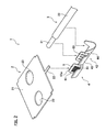
- FIG. 1 is a perspective view illustrating a connecting structure for a bus bar and an electrical wire according to an embodiment of the present invention.
- FIG. 2 is an exploded perspective view of the connecting structure for the bus bar and the electrical wire according to the embodiment of the present invention.
- FIG. 3 is a perspective view of a crimp terminal according to the embodiment of the present invention.
- a connecting structure 1 uses a crimp terminal 4 to connect a bus bar 2 and an electrical wire 3 together.
- the connecting structure 1 is used in a power supply device mounted on an electric vehicle or a hybrid vehicle.
- the power supply device (not illustrated) includes plural battery cells arranged side by side. Each of the battery cells has one end at which a positive electrode and a negative electrode protrude. The plural battery cells are arranged in such a manner that the positive electrode of one of the adjacent battery cells is connected to the negative electrode of the other battery cell.
- the bus bar 2 connects the adjacent battery cells in series or provides a connection between the battery cell and an external device. Thus, the number of the bus bars 2 for use in the connecting structure 1 is set according to the number of battery cells and the number of external devices.
- the bus bar 2 includes a bus bar body 21 and a bus bar crimp portion 22 , and is made of an electrically conductive metal such as an aluminum material or a copper material.
- the bus bar 2 is made of the aluminum material. Due to the fact that the bus bar 2 is made of the aluminum material, an oxide film develops on the surface of the bus bar 2 with the passage of time. However, the oxide film on the bus bar crimp portion 22 is broken by an oxide film breaking means 5 formed in the crimp terminal 4 .
- the bus bar body 21 is formed in the shape of a flat plate such as a rectangular, and is connected to the battery cell or the external device.
- the bus bar body 21 has two through-holes 23 formed therethrough, and the positive electrode and the negative electrode of the battery cell or a terminal of the external device pass through the through-holes 23 .
- the bus bar crimp portion 22 is formed in the shape of a plate, protruding outward from an end portion of the bus bar body 21 .
- the crimp terminal 4 is crimped to the bus bar crimp portion 22 . This crimping allows the bus bar crimp portion 22 to be connected to the crimp terminal 4 .
- a coated electrical wire constructed of a core wire 31 and a coating portion 32 coating an outer periphery of the core wire 31 is used as the electrical wire 3 .
- the core wire 31 is formed to a predetermined thickness by twisting plural strands made of a copper material.
- the coating portion 32 is made of an insulating resin.
- the electrical wire 3 with the core wire 31 exposed by peeling the coating portion 32 , is connected via the crimp terminal 4 to the bus bar 2 .
- the crimp terminal 4 is clamped to the bus bar 2 and the electrical wire 3 thereby to provide an electrical connection between the bus bar 2 and the electrical wire 3 .
- the crimp terminal 4 includes a bus bar-connecting section 41 and an electrical wire-connecting section 42 .
- the crimp terminal 4 is made of an electrically conductive metal such as stainless steel or spring steel.
- the bus bar-connecting section 41 of the crimp terminal 4 is crimped to the bus bar crimp portion 22 of the bus bar 2 . This allows an electrical connection between the crimp terminal 4 and the bus bar 2 .
- the electrical wire-connecting section 42 is formed so as to be linked via a linking portion 45 to the bus bar-connecting section 41 , and the electrical wire-connecting section 42 includes a core wire crimp portion 43 and a coating clamping portion 44 .
- the core wire crimp portion 43 is located in a portion (on the bus bar-connecting section 41 side) in which the electrical wire-connecting section 42 is adjacent to the linking portion 45 .
- the core wire crimp portion 43 is crimped to the core wire 31 of the peeled electrical wire 3 . This allows an electrical connection between the crimp terminal 4 and the electrical wire 3 .
- the coating clamping portion 44 is disposed on the opposite side from the portion in which the electrical wire-connecting section 42 is adjacent to the linking portion 45 .
- the coating clamping portion 44 is clamped to the coating portion 32 of the electrical wire 3 .
- the coating clamping portion 44 is clamped thereby to fix the crimp terminal 4 to the electrical wire 3 .
- the oxide film breaking means 5 is formed in the crimp terminal 4 , as illustrated in FIGS. 2 and 3 .
- the oxide film breaking means 5 is provided on a crimp surface 41 a at a top surface of the bus bar-connecting section 41 .
- the oxide film breaking means 5 is formed of a serration 51 of the crimp surface 41 a of the bus bar-connecting section 41 .
- the serration 51 is formed by forming plural small rectangular grooves in the crimp surface 41 a of the bus bar-connecting section 41 .
- the plural rectangular grooves are arranged in a grid pattern on the crimp surface 41 a of the bus bar-connecting section 41 .
- plural ridges 53 are formed on the core wire crimp portion 43 of the crimp terminal 4 .
- the plural ridges 53 are formed along a direction substantially orthogonal to an axial direction of the core wire 31 of the electrical wire 3 .
- the plural ridges 53 are formed on the core wire crimp portion 43 thereby to restrain an axial misalignment of the core wire 31 crimped to the core wire crimp portion 43 and thus enable retaining the core wire 31 .
- the bus bar crimp portion 22 of the bus bar 2 is placed on the bus bar-connecting section 41 of the crimp terminal 4 , the core wire 31 exposed by peeling the electrical wire 3 is placed on the core wire crimp portion 43 of the crimp terminal 4 , and the coating portion 32 of the electrical wire 3 is placed on the coating clamping portion 44 of the crimp terminal 4 .
- the bus bar-connecting section 41 , the core wire crimp portion 43 and the coating clamping portion 44 are clamped thereby to crimp the bus bar-connecting section 41 to the bus bar crimp portion 22 and crimp the core wire crimp portion 43 to the core wire 31 of the electrical wire 3 .
- the bus bar 2 and the electrical wire 3 are electrically connected via the crimp terminal 4 .
- the coating clamping portion 44 is crimped to the coating portion 32 of the electrical wire 3 thereby to retain the electrical wire 3 on the crimp terminal 4 .
- the plural ridges 53 formed on the core wire crimp portion 43 bite into the core wire 31 of the electrical wire 3 to thus restrain the axial misalignment of the core wire 31 . Therefore, a good connection between the electrical wire 3 and the crimp terminal 4 is achieved.
- a connection between the bus bar 2 and the core wire 31 of the electrical wire 3 and fixing of the coating portion 32 of the electrical wire 3 can be accomplished merely by a process for crimping the crimp terminal 4 to the bus bar 2 and the electrical wire 3 . Therefore, the number of processes for connection is reduced, thus achieving a simplification of a connection operation.
- the bus bar-connecting section 41 of the crimp terminal 4 is provided with the oxide film breaking means 5 formed of the serration 51 . Therefore, even if the bus bar 2 is made of the aluminum material, when the crimp terminal 4 is crimped to the bus bar 2 , the oxide film on the bus bar 2 is broken. As a result, connection without impairment of electrical connection performance can be accomplished.
- the plural ridges 53 are formed on the core wire crimp portion 43 of the crimp terminal 4 to thus enabling restraining the axial misalignment of the core wire 31 . Therefore, the crimp terminal 4 can retain the core wire 31 with reliability.
- the bus bar 2 is made of the aluminum material.
- the core wire 31 of the electrical wire 3 is made of an aluminum material
- the core wire crimp portion 43 of the crimp terminal 4 is provided with the oxide film breaking means 5 formed of the serration 51 , and thereby, when the crimp terminal 4 is crimped to the electrical wire 3 , the oxide film on the core wire 31 can be broken.
- the core wire crimp portion 43 is provided with the oxide film breaking means 5 , and thereby, even if the oxide film develops on the core wire 31 , the crimp terminal 4 is crimped to the electrical wire 3 thereby to enable breaking the oxide film on the core wire 31 . Therefore, impairment of the electrical connection performance between the electrical wire 3 and the crimp terminal 4 can be prevented.
- the bus bar-connecting section 41 and the core wire crimp portion 43 of the crimp terminal 4 are provided with the oxide film breaking means 5 formed of the serration 51 , and thereby, when the crimp terminal 4 is crimped to the bus bar 2 and the electrical wire 3 , the oxide films on the bus bar 2 and the core wire 31 can be broken.
- the serration 51 is formed of the plural rectangular grooves arranged in the grid pattern, the serration 51 may be formed of plural oblong grooves arranged in one direction.
Landscapes
- Chemical & Material Sciences (AREA)
- Chemical Kinetics & Catalysis (AREA)
- Electrochemistry (AREA)
- General Chemical & Material Sciences (AREA)
- Connections Effected By Soldering, Adhesion, Or Permanent Deformation (AREA)
- Connection Of Batteries Or Terminals (AREA)
Applications Claiming Priority (3)
| Application Number | Priority Date | Filing Date | Title |
|---|---|---|---|
| JP2012-205335 | 2012-09-19 | ||
| JP2012205335A JP6033019B2 (ja) | 2012-09-19 | 2012-09-19 | バスバーと電線の接続構造 |
| PCT/JP2013/075125 WO2014046116A1 (ja) | 2012-09-19 | 2013-09-18 | バスバーと電線との接続構造 |
Related Parent Applications (1)
| Application Number | Title | Priority Date | Filing Date |
|---|---|---|---|
| PCT/JP2013/075125 Continuation WO2014046116A1 (ja) | 2012-09-19 | 2013-09-18 | バスバーと電線との接続構造 |
Publications (2)
| Publication Number | Publication Date |
|---|---|
| US20150188244A1 US20150188244A1 (en) | 2015-07-02 |
| US9806441B2 true US9806441B2 (en) | 2017-10-31 |
Family
ID=50341426
Family Applications (1)
| Application Number | Title | Priority Date | Filing Date |
|---|---|---|---|
| US14/645,586 Active US9806441B2 (en) | 2012-09-19 | 2015-03-12 | Connecting structure for bus bar and electrical wire |
Country Status (5)
| Country | Link |
|---|---|
| US (1) | US9806441B2 (ja) |
| EP (1) | EP2899809B1 (ja) |
| JP (1) | JP6033019B2 (ja) |
| CA (1) | CA2884369A1 (ja) |
| WO (1) | WO2014046116A1 (ja) |
Cited By (1)
| Publication number | Priority date | Publication date | Assignee | Title |
|---|---|---|---|---|
| US20190252841A1 (en) * | 2018-02-13 | 2019-08-15 | Sumida Corporation | Tip structure of flat wire and method for manufacturing the tip structure |
Families Citing this family (16)
| Publication number | Priority date | Publication date | Assignee | Title |
|---|---|---|---|---|
| DE102013221870B4 (de) * | 2013-10-28 | 2021-09-30 | Te Connectivity Germany Gmbh | Verbindungsanordnung zur Verbindung mindestens einer als Zelle ausgestalteten Spannungsquelle und/oder -senke mit einem externen elektrischen Bauelement und elektrische Anordnung umfassend eine Verbindungsanordnung |
| JP6357334B2 (ja) * | 2014-03-28 | 2018-07-11 | 矢崎総業株式会社 | 圧着端子と電線の接続構造 |
| TWM485568U (zh) * | 2014-06-05 | 2014-09-01 | Huang Da Lun | 電池盒及其極片組 |
| JP6259417B2 (ja) * | 2014-09-25 | 2018-01-10 | 矢崎総業株式会社 | 端子金具及び端子金具の接続構造 |
| DE102015209855A1 (de) * | 2015-05-28 | 2016-12-01 | Te Connectivity Germany Gmbh | Elektrisches Kontaktierungselement mit einer feinstrukturierten Kontaktierungsfläche |
| JP2017033776A (ja) * | 2015-08-03 | 2017-02-09 | 矢崎総業株式会社 | 圧着端子及びその製造方法並びに電線、ワイヤハーネス |
| EP3139718A1 (en) * | 2015-09-03 | 2017-03-08 | Autoliv Development AB | Housing for enclosing at least one electrical component of a motor vehicle, and method of mounting a housing |
| US9837774B2 (en) | 2015-11-04 | 2017-12-05 | Yazaki Corporation | Fixing structure between busbar and terminal |
| JP2019008877A (ja) * | 2017-06-20 | 2019-01-17 | 矢崎総業株式会社 | 電線接続バスバ及び導電モジュール |
| JP7066340B2 (ja) * | 2017-06-20 | 2022-05-13 | 矢崎総業株式会社 | 電線接続バスバ及び導電モジュール |
| JP7004200B2 (ja) * | 2017-11-08 | 2022-02-10 | トヨタ自動車株式会社 | 組電池の製造方法、および組電池 |
| KR102508168B1 (ko) | 2018-01-10 | 2023-03-09 | 삼성에스디아이 주식회사 | 배터리 팩 |
| US10665964B2 (en) * | 2018-07-13 | 2020-05-26 | Te Connectivity Corporation | Electrical terminals having bi-directional serrations and method of manufacture |
| JP2020191176A (ja) * | 2019-05-20 | 2020-11-26 | 矢崎総業株式会社 | 導電モジュール |
| US11043766B2 (en) * | 2019-08-29 | 2021-06-22 | J.S.T. Corporation | Electrical male terminal, and methods for connecting thereof |
| CN112531294A (zh) * | 2020-12-21 | 2021-03-19 | 常德中科多源电力融合技术研究院 | 一种软包锂离子电池极耳连接件及连接方法 |
Citations (22)
| Publication number | Priority date | Publication date | Assignee | Title |
|---|---|---|---|---|
| US3030603A (en) * | 1959-08-31 | 1962-04-17 | Malco Mfg Co | Connector |
| US3715705A (en) | 1971-03-29 | 1973-02-06 | Thomas & Betts Corp | Multicompartment connector |
| US3831132A (en) * | 1971-04-29 | 1974-08-20 | Molex Inc | Crimp terminal for aluminum wire |
| JPH09223523A (ja) | 1996-02-16 | 1997-08-26 | Oki Densen Kk | 異種導体もしくは導体サイズ変換型圧着端子 |
| JP2003045409A (ja) | 2001-07-31 | 2003-02-14 | Yazaki Corp | 電源装置 |
| JP2003243057A (ja) | 2002-02-18 | 2003-08-29 | Auto Network Gijutsu Kenkyusho:Kk | 電線接続端子 |
| JP2004199934A (ja) | 2002-12-17 | 2004-07-15 | Auto Network Gijutsu Kenkyusho:Kk | コネクタ端子及びその製造方法 |
| JP2006004733A (ja) | 2004-06-17 | 2006-01-05 | Yazaki Corp | ボルトを用いた端子接続構造とそれを備えた電気接続箱 |
| JP2008234935A (ja) | 2007-03-19 | 2008-10-02 | Denso Corp | バスバー配線式回路装置の組み立て方法 |
| JP2010015900A (ja) | 2008-07-04 | 2010-01-21 | Furukawa Automotive Systems Inc | 電線の固定構造 |
| JP2010027505A (ja) | 2008-07-23 | 2010-02-04 | Sumitomo Wiring Syst Ltd | 端子金具および端子金具付き電線 |
| US7722416B2 (en) * | 2008-10-02 | 2010-05-25 | Delphi Technologies, Inc. | Electrical connection system for use on aluminum wires |
| JP2010225449A (ja) | 2009-03-24 | 2010-10-07 | Autonetworks Technologies Ltd | 接続ユニット |
| US7867014B2 (en) * | 2007-11-16 | 2011-01-11 | Yazaki Corporation | Press-clamping terminal for aluminum wire |
| JP2011040332A (ja) | 2009-08-18 | 2011-02-24 | Yazaki Corp | バスバ |
| JP2011187400A (ja) | 2010-03-11 | 2011-09-22 | Pl:Kk | アルミニウム体の接続構造およびコネクタ |
| US20110244309A1 (en) * | 2010-03-30 | 2011-10-06 | Sang-Won Byun | Secondary battery and secondary battery module |
| US20110294368A1 (en) * | 2009-02-23 | 2011-12-01 | Sumitomo Wiring Systems, Ltd. | Terminal fitting |
| JP2012059500A (ja) | 2010-09-08 | 2012-03-22 | Auto Network Gijutsu Kenkyusho:Kk | 電池モジュール |
| JP2012059658A (ja) | 2010-09-13 | 2012-03-22 | Auto Network Gijutsu Kenkyusho:Kk | バスバー |
| US8221171B2 (en) * | 2007-11-01 | 2012-07-17 | Autonetworks Technologies, Ltd. | Crimp terminal, terminal-provided wire, and manufacturing method thereof |
| US20120322320A1 (en) * | 2010-03-02 | 2012-12-20 | Autonetworks Technologies, Ltd. | Battery connecting assembly |
-
2012
- 2012-09-19 JP JP2012205335A patent/JP6033019B2/ja active Active
-
2013
- 2013-09-18 CA CA2884369A patent/CA2884369A1/en not_active Abandoned
- 2013-09-18 WO PCT/JP2013/075125 patent/WO2014046116A1/ja active Application Filing
- 2013-09-18 EP EP13838872.3A patent/EP2899809B1/en active Active
-
2015
- 2015-03-12 US US14/645,586 patent/US9806441B2/en active Active
Patent Citations (24)
| Publication number | Priority date | Publication date | Assignee | Title |
|---|---|---|---|---|
| US3030603A (en) * | 1959-08-31 | 1962-04-17 | Malco Mfg Co | Connector |
| US3715705A (en) | 1971-03-29 | 1973-02-06 | Thomas & Betts Corp | Multicompartment connector |
| US3831132A (en) * | 1971-04-29 | 1974-08-20 | Molex Inc | Crimp terminal for aluminum wire |
| JPH09223523A (ja) | 1996-02-16 | 1997-08-26 | Oki Densen Kk | 異種導体もしくは導体サイズ変換型圧着端子 |
| JP2003045409A (ja) | 2001-07-31 | 2003-02-14 | Yazaki Corp | 電源装置 |
| JP2003243057A (ja) | 2002-02-18 | 2003-08-29 | Auto Network Gijutsu Kenkyusho:Kk | 電線接続端子 |
| JP2004199934A (ja) | 2002-12-17 | 2004-07-15 | Auto Network Gijutsu Kenkyusho:Kk | コネクタ端子及びその製造方法 |
| JP2006004733A (ja) | 2004-06-17 | 2006-01-05 | Yazaki Corp | ボルトを用いた端子接続構造とそれを備えた電気接続箱 |
| JP2008234935A (ja) | 2007-03-19 | 2008-10-02 | Denso Corp | バスバー配線式回路装置の組み立て方法 |
| US8221171B2 (en) * | 2007-11-01 | 2012-07-17 | Autonetworks Technologies, Ltd. | Crimp terminal, terminal-provided wire, and manufacturing method thereof |
| US7867014B2 (en) * | 2007-11-16 | 2011-01-11 | Yazaki Corporation | Press-clamping terminal for aluminum wire |
| JP2010015900A (ja) | 2008-07-04 | 2010-01-21 | Furukawa Automotive Systems Inc | 電線の固定構造 |
| JP2010027505A (ja) | 2008-07-23 | 2010-02-04 | Sumitomo Wiring Syst Ltd | 端子金具および端子金具付き電線 |
| US7722416B2 (en) * | 2008-10-02 | 2010-05-25 | Delphi Technologies, Inc. | Electrical connection system for use on aluminum wires |
| US20110294368A1 (en) * | 2009-02-23 | 2011-12-01 | Sumitomo Wiring Systems, Ltd. | Terminal fitting |
| JP2010225449A (ja) | 2009-03-24 | 2010-10-07 | Autonetworks Technologies Ltd | 接続ユニット |
| JP2011040332A (ja) | 2009-08-18 | 2011-02-24 | Yazaki Corp | バスバ |
| US20120208410A1 (en) | 2009-08-18 | 2012-08-16 | Yazaki Corporation | Busbar |
| US20120322320A1 (en) * | 2010-03-02 | 2012-12-20 | Autonetworks Technologies, Ltd. | Battery connecting assembly |
| JP2011187400A (ja) | 2010-03-11 | 2011-09-22 | Pl:Kk | アルミニウム体の接続構造およびコネクタ |
| US20120295496A1 (en) | 2010-03-11 | 2012-11-22 | Mitsuru Suzuki | Connecting structure for an aluminum electric conductor and a connector |
| US20110244309A1 (en) * | 2010-03-30 | 2011-10-06 | Sang-Won Byun | Secondary battery and secondary battery module |
| JP2012059500A (ja) | 2010-09-08 | 2012-03-22 | Auto Network Gijutsu Kenkyusho:Kk | 電池モジュール |
| JP2012059658A (ja) | 2010-09-13 | 2012-03-22 | Auto Network Gijutsu Kenkyusho:Kk | バスバー |
Non-Patent Citations (4)
| Title |
|---|
| The extended European search report dated Jan. 26, 2016 in the counterpart European patent application. |
| The Japanese Duplicate of Opposition dated Jun. 23, 2017 in the counterpart Japanese patent application. |
| The Japanese Office Action dated Jul. 19, 2016 in the counterpart Japanese patent application. |
| The Japanese Office Action dated May 10, 2016 in the counterpart Japanese patent application. |
Cited By (2)
| Publication number | Priority date | Publication date | Assignee | Title |
|---|---|---|---|---|
| US20190252841A1 (en) * | 2018-02-13 | 2019-08-15 | Sumida Corporation | Tip structure of flat wire and method for manufacturing the tip structure |
| US10601196B2 (en) * | 2018-02-13 | 2020-03-24 | Sumida Corporation | Tip structure of flat wire and method for manufacturing the tip structure |
Also Published As
| Publication number | Publication date |
|---|---|
| EP2899809B1 (en) | 2017-11-29 |
| EP2899809A4 (en) | 2016-02-24 |
| EP2899809A1 (en) | 2015-07-29 |
| US20150188244A1 (en) | 2015-07-02 |
| JP2014060093A (ja) | 2014-04-03 |
| JP6033019B2 (ja) | 2016-11-30 |
| WO2014046116A1 (ja) | 2014-03-27 |
| CA2884369A1 (en) | 2014-03-27 |
Similar Documents
| Publication | Publication Date | Title |
|---|---|---|
| US9806441B2 (en) | Connecting structure for bus bar and electrical wire | |
| JP6682481B2 (ja) | 導体モジュール | |
| JP6041393B2 (ja) | 電気的接続バス | |
| US7862951B2 (en) | Fuel cell and fuel cell connector | |
| JP6588110B2 (ja) | バッテリモジュールのためのカバー組立体 | |
| JP6685422B2 (ja) | マルチワイヤ平板状ケーブルを有する端子アセンブリ | |
| CN106953060B (zh) | 汇流条模块和汇流条模块制造方法 | |
| US7611384B2 (en) | Battery terminal connector | |
| EP3082177B1 (en) | Secondary cell module | |
| WO2010052788A1 (ja) | 二次電池用ブスバー及び二次電池モジュール | |
| JP2019032931A (ja) | 導体モジュール | |
| JP6612207B2 (ja) | 導体モジュール | |
| JP2016018741A (ja) | 電池配線モジュール | |
| JP5825991B2 (ja) | 蓄電池用の電線配索構造 | |
| JP2019520686A (ja) | バッテリシステム用コネクタアセンブリ | |
| EP3451419B1 (en) | Connection module | |
| JP2013080693A (ja) | 電池用配線モジュール | |
| US9912082B2 (en) | Electric wire connection structure | |
| KR20160077146A (ko) | 전지의 형태인 적어도 하나의 전압원 및/또는 전원 싱크를 외부 전기 컴포넌트에 연결하기 위한 연결 장치 및 연결 장치를 포함하는 전기 장치 | |
| US20180248280A1 (en) | Terminal-equipped electrical wire and wiring module | |
| WO2019146197A1 (ja) | 蓄電モジュール | |
| WO2011155369A1 (ja) | 電池接続プレート | |
| JP2019053938A (ja) | フラットケーブル及びワイヤーハーネス | |
| JP7444637B2 (ja) | バスバーモジュール | |
| JP7144286B2 (ja) | 電線及び電線束 |
Legal Events
| Date | Code | Title | Description |
|---|---|---|---|
| AS | Assignment |
Owner name: YAZAKI CORPORATION, JAPAN Free format text: ASSIGNMENT OF ASSIGNORS INTEREST;ASSIGNORS:YOSHIOKA, NOBUAKI;SUZUKI, KEIGO;REEL/FRAME:035148/0022 Effective date: 20141205 |
|
| STCF | Information on status: patent grant |
Free format text: PATENTED CASE |
|
| MAFP | Maintenance fee payment |
Free format text: PAYMENT OF MAINTENANCE FEE, 4TH YEAR, LARGE ENTITY (ORIGINAL EVENT CODE: M1551); ENTITY STATUS OF PATENT OWNER: LARGE ENTITY Year of fee payment: 4 |
|
| AS | Assignment |
Owner name: YAZAKI CORPORATION, JAPAN Free format text: CHANGE OF ADDRESS;ASSIGNOR:YAZAKI CORPORATION;REEL/FRAME:063845/0802 Effective date: 20230331 |