US9806360B2 - Unit cell for solid-oxide fuel cell and solid-oxide fuel cell using same - Google Patents
Unit cell for solid-oxide fuel cell and solid-oxide fuel cell using same Download PDFInfo
- Publication number
- US9806360B2 US9806360B2 US14/380,107 US201314380107A US9806360B2 US 9806360 B2 US9806360 B2 US 9806360B2 US 201314380107 A US201314380107 A US 201314380107A US 9806360 B2 US9806360 B2 US 9806360B2
- Authority
- US
- United States
- Prior art keywords
- solid
- fuel cell
- oxide fuel
- anode
- cell
- Prior art date
- Legal status (The legal status is an assumption and is not a legal conclusion. Google has not performed a legal analysis and makes no representation as to the accuracy of the status listed.)
- Active, expires
Links
Images




Classifications
-
- H—ELECTRICITY
- H01—ELECTRIC ELEMENTS
- H01M—PROCESSES OR MEANS, e.g. BATTERIES, FOR THE DIRECT CONVERSION OF CHEMICAL ENERGY INTO ELECTRICAL ENERGY
- H01M8/00—Fuel cells; Manufacture thereof
- H01M8/04—Auxiliary arrangements, e.g. for control of pressure or for circulation of fluids
- H01M8/04082—Arrangements for control of reactant parameters, e.g. pressure or concentration
- H01M8/04201—Reactant storage and supply, e.g. means for feeding, pipes
-
- H—ELECTRICITY
- H01—ELECTRIC ELEMENTS
- H01M—PROCESSES OR MEANS, e.g. BATTERIES, FOR THE DIRECT CONVERSION OF CHEMICAL ENERGY INTO ELECTRICAL ENERGY
- H01M8/00—Fuel cells; Manufacture thereof
- H01M8/10—Fuel cells with solid electrolytes
- H01M8/12—Fuel cells with solid electrolytes operating at high temperature, e.g. with stabilised ZrO2 electrolyte
-
- H—ELECTRICITY
- H01—ELECTRIC ELEMENTS
- H01M—PROCESSES OR MEANS, e.g. BATTERIES, FOR THE DIRECT CONVERSION OF CHEMICAL ENERGY INTO ELECTRICAL ENERGY
- H01M8/00—Fuel cells; Manufacture thereof
- H01M8/02—Details
-
- H—ELECTRICITY
- H01—ELECTRIC ELEMENTS
- H01M—PROCESSES OR MEANS, e.g. BATTERIES, FOR THE DIRECT CONVERSION OF CHEMICAL ENERGY INTO ELECTRICAL ENERGY
- H01M8/00—Fuel cells; Manufacture thereof
- H01M8/02—Details
- H01M8/0202—Collectors; Separators, e.g. bipolar separators; Interconnectors
- H01M8/0258—Collectors; Separators, e.g. bipolar separators; Interconnectors characterised by the configuration of channels, e.g. by the flow field of the reactant or coolant
-
- H—ELECTRICITY
- H01—ELECTRIC ELEMENTS
- H01M—PROCESSES OR MEANS, e.g. BATTERIES, FOR THE DIRECT CONVERSION OF CHEMICAL ENERGY INTO ELECTRICAL ENERGY
- H01M8/00—Fuel cells; Manufacture thereof
- H01M8/02—Details
- H01M8/0271—Sealing or supporting means around electrodes, matrices or membranes
-
- H—ELECTRICITY
- H01—ELECTRIC ELEMENTS
- H01M—PROCESSES OR MEANS, e.g. BATTERIES, FOR THE DIRECT CONVERSION OF CHEMICAL ENERGY INTO ELECTRICAL ENERGY
- H01M8/00—Fuel cells; Manufacture thereof
- H01M8/02—Details
- H01M8/0271—Sealing or supporting means around electrodes, matrices or membranes
- H01M8/0273—Sealing or supporting means around electrodes, matrices or membranes with sealing or supporting means in the form of a frame
-
- H—ELECTRICITY
- H01—ELECTRIC ELEMENTS
- H01M—PROCESSES OR MEANS, e.g. BATTERIES, FOR THE DIRECT CONVERSION OF CHEMICAL ENERGY INTO ELECTRICAL ENERGY
- H01M8/00—Fuel cells; Manufacture thereof
- H01M8/02—Details
- H01M8/0297—Arrangements for joining electrodes, reservoir layers, heat exchange units or bipolar separators to each other
-
- H—ELECTRICITY
- H01—ELECTRIC ELEMENTS
- H01M—PROCESSES OR MEANS, e.g. BATTERIES, FOR THE DIRECT CONVERSION OF CHEMICAL ENERGY INTO ELECTRICAL ENERGY
- H01M8/00—Fuel cells; Manufacture thereof
- H01M8/10—Fuel cells with solid electrolytes
- H01M8/12—Fuel cells with solid electrolytes operating at high temperature, e.g. with stabilised ZrO2 electrolyte
- H01M8/1213—Fuel cells with solid electrolytes operating at high temperature, e.g. with stabilised ZrO2 electrolyte characterised by the electrode/electrolyte combination or the supporting material
-
- H—ELECTRICITY
- H01—ELECTRIC ELEMENTS
- H01M—PROCESSES OR MEANS, e.g. BATTERIES, FOR THE DIRECT CONVERSION OF CHEMICAL ENERGY INTO ELECTRICAL ENERGY
- H01M8/00—Fuel cells; Manufacture thereof
- H01M8/10—Fuel cells with solid electrolytes
- H01M8/12—Fuel cells with solid electrolytes operating at high temperature, e.g. with stabilised ZrO2 electrolyte
- H01M8/124—Fuel cells with solid electrolytes operating at high temperature, e.g. with stabilised ZrO2 electrolyte characterised by the process of manufacturing or by the material of the electrolyte
- H01M8/1246—Fuel cells with solid electrolytes operating at high temperature, e.g. with stabilised ZrO2 electrolyte characterised by the process of manufacturing or by the material of the electrolyte the electrolyte consisting of oxides
-
- H—ELECTRICITY
- H01—ELECTRIC ELEMENTS
- H01M—PROCESSES OR MEANS, e.g. BATTERIES, FOR THE DIRECT CONVERSION OF CHEMICAL ENERGY INTO ELECTRICAL ENERGY
- H01M8/00—Fuel cells; Manufacture thereof
- H01M8/24—Grouping of fuel cells, e.g. stacking of fuel cells
-
- H—ELECTRICITY
- H01—ELECTRIC ELEMENTS
- H01M—PROCESSES OR MEANS, e.g. BATTERIES, FOR THE DIRECT CONVERSION OF CHEMICAL ENERGY INTO ELECTRICAL ENERGY
- H01M8/00—Fuel cells; Manufacture thereof
- H01M8/24—Grouping of fuel cells, e.g. stacking of fuel cells
- H01M8/2404—Processes or apparatus for grouping fuel cells
-
- H—ELECTRICITY
- H01—ELECTRIC ELEMENTS
- H01M—PROCESSES OR MEANS, e.g. BATTERIES, FOR THE DIRECT CONVERSION OF CHEMICAL ENERGY INTO ELECTRICAL ENERGY
- H01M8/00—Fuel cells; Manufacture thereof
- H01M8/24—Grouping of fuel cells, e.g. stacking of fuel cells
- H01M8/241—Grouping of fuel cells, e.g. stacking of fuel cells with solid or matrix-supported electrolytes
-
- H—ELECTRICITY
- H01—ELECTRIC ELEMENTS
- H01M—PROCESSES OR MEANS, e.g. BATTERIES, FOR THE DIRECT CONVERSION OF CHEMICAL ENERGY INTO ELECTRICAL ENERGY
- H01M8/00—Fuel cells; Manufacture thereof
- H01M8/24—Grouping of fuel cells, e.g. stacking of fuel cells
- H01M8/241—Grouping of fuel cells, e.g. stacking of fuel cells with solid or matrix-supported electrolytes
- H01M8/2425—High-temperature cells with solid electrolytes
-
- H—ELECTRICITY
- H01—ELECTRIC ELEMENTS
- H01M—PROCESSES OR MEANS, e.g. BATTERIES, FOR THE DIRECT CONVERSION OF CHEMICAL ENERGY INTO ELECTRICAL ENERGY
- H01M8/00—Fuel cells; Manufacture thereof
- H01M8/24—Grouping of fuel cells, e.g. stacking of fuel cells
- H01M8/2457—Grouping of fuel cells, e.g. stacking of fuel cells with both reactants being gaseous or vaporised
-
- H—ELECTRICITY
- H01—ELECTRIC ELEMENTS
- H01M—PROCESSES OR MEANS, e.g. BATTERIES, FOR THE DIRECT CONVERSION OF CHEMICAL ENERGY INTO ELECTRICAL ENERGY
- H01M8/00—Fuel cells; Manufacture thereof
- H01M8/24—Grouping of fuel cells, e.g. stacking of fuel cells
- H01M8/2465—Details of groupings of fuel cells
- H01M8/2483—Details of groupings of fuel cells characterised by internal manifolds
-
- H—ELECTRICITY
- H01—ELECTRIC ELEMENTS
- H01M—PROCESSES OR MEANS, e.g. BATTERIES, FOR THE DIRECT CONVERSION OF CHEMICAL ENERGY INTO ELECTRICAL ENERGY
- H01M8/00—Fuel cells; Manufacture thereof
- H01M8/24—Grouping of fuel cells, e.g. stacking of fuel cells
- H01M8/2465—Details of groupings of fuel cells
- H01M8/2484—Details of groupings of fuel cells characterised by external manifolds
-
- H01M2/1673—
-
- H—ELECTRICITY
- H01—ELECTRIC ELEMENTS
- H01M—PROCESSES OR MEANS, e.g. BATTERIES, FOR THE DIRECT CONVERSION OF CHEMICAL ENERGY INTO ELECTRICAL ENERGY
- H01M8/00—Fuel cells; Manufacture thereof
- H01M8/10—Fuel cells with solid electrolytes
- H01M8/12—Fuel cells with solid electrolytes operating at high temperature, e.g. with stabilised ZrO2 electrolyte
- H01M2008/1293—Fuel cells with solid oxide electrolytes
-
- H—ELECTRICITY
- H01—ELECTRIC ELEMENTS
- H01M—PROCESSES OR MEANS, e.g. BATTERIES, FOR THE DIRECT CONVERSION OF CHEMICAL ENERGY INTO ELECTRICAL ENERGY
- H01M2300/00—Electrolytes
- H01M2300/0017—Non-aqueous electrolytes
- H01M2300/0065—Solid electrolytes
- H01M2300/0068—Solid electrolytes inorganic
- H01M2300/0071—Oxides
-
- H—ELECTRICITY
- H01—ELECTRIC ELEMENTS
- H01M—PROCESSES OR MEANS, e.g. BATTERIES, FOR THE DIRECT CONVERSION OF CHEMICAL ENERGY INTO ELECTRICAL ENERGY
- H01M50/00—Constructional details or processes of manufacture of the non-active parts of electrochemical cells other than fuel cells, e.g. hybrid cells
- H01M50/40—Separators; Membranes; Diaphragms; Spacing elements inside cells
- H01M50/46—Separators, membranes or diaphragms characterised by their combination with electrodes
-
- H—ELECTRICITY
- H01—ELECTRIC ELEMENTS
- H01M—PROCESSES OR MEANS, e.g. BATTERIES, FOR THE DIRECT CONVERSION OF CHEMICAL ENERGY INTO ELECTRICAL ENERGY
- H01M8/00—Fuel cells; Manufacture thereof
- H01M8/02—Details
- H01M8/0202—Collectors; Separators, e.g. bipolar separators; Interconnectors
-
- H—ELECTRICITY
- H01—ELECTRIC ELEMENTS
- H01M—PROCESSES OR MEANS, e.g. BATTERIES, FOR THE DIRECT CONVERSION OF CHEMICAL ENERGY INTO ELECTRICAL ENERGY
- H01M8/00—Fuel cells; Manufacture thereof
- H01M8/10—Fuel cells with solid electrolytes
- H01M8/12—Fuel cells with solid electrolytes operating at high temperature, e.g. with stabilised ZrO2 electrolyte
- H01M8/124—Fuel cells with solid electrolytes operating at high temperature, e.g. with stabilised ZrO2 electrolyte characterised by the process of manufacturing or by the material of the electrolyte
-
- H—ELECTRICITY
- H01—ELECTRIC ELEMENTS
- H01M—PROCESSES OR MEANS, e.g. BATTERIES, FOR THE DIRECT CONVERSION OF CHEMICAL ENERGY INTO ELECTRICAL ENERGY
- H01M8/00—Fuel cells; Manufacture thereof
- H01M8/14—Fuel cells with fused electrolytes
- H01M8/141—Fuel cells with fused electrolytes the anode and the cathode being gas-permeable electrodes or electrode layers
- H01M8/142—Fuel cells with fused electrolytes the anode and the cathode being gas-permeable electrodes or electrode layers with matrix-supported or semi-solid matrix-reinforced electrolyte
-
- Y—GENERAL TAGGING OF NEW TECHNOLOGICAL DEVELOPMENTS; GENERAL TAGGING OF CROSS-SECTIONAL TECHNOLOGIES SPANNING OVER SEVERAL SECTIONS OF THE IPC; TECHNICAL SUBJECTS COVERED BY FORMER USPC CROSS-REFERENCE ART COLLECTIONS [XRACs] AND DIGESTS
- Y02—TECHNOLOGIES OR APPLICATIONS FOR MITIGATION OR ADAPTATION AGAINST CLIMATE CHANGE
- Y02E—REDUCTION OF GREENHOUSE GAS [GHG] EMISSIONS, RELATED TO ENERGY GENERATION, TRANSMISSION OR DISTRIBUTION
- Y02E60/00—Enabling technologies; Technologies with a potential or indirect contribution to GHG emissions mitigation
- Y02E60/10—Energy storage using batteries
-
- Y—GENERAL TAGGING OF NEW TECHNOLOGICAL DEVELOPMENTS; GENERAL TAGGING OF CROSS-SECTIONAL TECHNOLOGIES SPANNING OVER SEVERAL SECTIONS OF THE IPC; TECHNICAL SUBJECTS COVERED BY FORMER USPC CROSS-REFERENCE ART COLLECTIONS [XRACs] AND DIGESTS
- Y02—TECHNOLOGIES OR APPLICATIONS FOR MITIGATION OR ADAPTATION AGAINST CLIMATE CHANGE
- Y02E—REDUCTION OF GREENHOUSE GAS [GHG] EMISSIONS, RELATED TO ENERGY GENERATION, TRANSMISSION OR DISTRIBUTION
- Y02E60/00—Enabling technologies; Technologies with a potential or indirect contribution to GHG emissions mitigation
- Y02E60/30—Hydrogen technology
- Y02E60/50—Fuel cells
-
- Y—GENERAL TAGGING OF NEW TECHNOLOGICAL DEVELOPMENTS; GENERAL TAGGING OF CROSS-SECTIONAL TECHNOLOGIES SPANNING OVER SEVERAL SECTIONS OF THE IPC; TECHNICAL SUBJECTS COVERED BY FORMER USPC CROSS-REFERENCE ART COLLECTIONS [XRACs] AND DIGESTS
- Y02—TECHNOLOGIES OR APPLICATIONS FOR MITIGATION OR ADAPTATION AGAINST CLIMATE CHANGE
- Y02P—CLIMATE CHANGE MITIGATION TECHNOLOGIES IN THE PRODUCTION OR PROCESSING OF GOODS
- Y02P70/00—Climate change mitigation technologies in the production process for final industrial or consumer products
- Y02P70/50—Manufacturing or production processes characterised by the final manufactured product
-
- Y02P70/56—
Definitions
- the present invention relates generally to a unit cell for a solid-oxide fuel cell and a solid-oxide fuel cell composed of the same.
- a solid-oxide fuel cell typically includes a unit cell as a basic structural element which comprises an electrolyte layer such as yttria-stabilized zirconia and an anode (fuel electrode) and a cathode (air electrode) attached to both sides of the electrolyte layer.
- an electrolyte layer such as yttria-stabilized zirconia has a dense structure so as not to allow fuel to be mixed with air whereas an anode and a cathode has a porous structure so as to allow fuel and hydrogen to be efficiently diffused.
- the solid-oxide fuel cell has been developed into a planar fuel cell and a tubular fuel cell. Furthermore, the tubular fuel cell may be classified into a cylindrical fuel cell and a flat-tubular fuel cell which is flattened to allow the fuel cells to be easily stacked.
- a method which is usually used in the production of the planar fuel cell and the tubular fuel cell is embodied by reducing resistance of a fuel cell by applying a thin electrolyte film on an electrode support in order to improve an output density of a unit cell for solid-oxide fuel cell.
- planar solid-oxide fuel cell although the layering of cells and the collection of current are facilitated because a metal connecting plate is used, there are disadvantages in that it is difficult to manufacture a large-area planar cell and an additional seal material is required to separate flows of fuel and air at upper and lower parts of the cell.
- a metal connector which is currently used as a connecting plate functioning to isolate fuel from air and to connect fuel cells in a series circuit manner, has shown the general problems of corrosion at a high temperature and deterioration of performance of the fuel cell owing to reaction of a cathode of a solid-oxide fuel cell and Cr volatilized from a stainless alloy.
- the problems of the connector have a critical effect on the durability of a solid-oxide fuel cell stack.
- a conventional solid-oxide fuel cell is configured to separate flows of fuel and air using a metal connector and a cell frame and supply the separated fuel and air to a front part and a rear part of the cell.
- the conventional solid-oxide fuel cell has problems such as difficulty in forming a seal between the cell and the metal plate, an increase in the weight of the stack and the load to the cell, an increase in volume of the stack and increases in manufacturing costs of the stack due to metal working costs.
- Conventional technologies relating to the field of the present invention may include Korean Pat. Nos. 10-0538555 and 2008-0131314.
- An object of the present invention is to provide a unit cell for a solid-oxide fuel cell which is composed of a plurality of layered unit cells and which does not need an additional separation plate and includes an anode provided with both an air flow hole and a fuel flow hole.
- Another object of the present invention is to provide a unit cell for a solid-oxide fuel cell and a solid-oxide fuel cell composed of the unit cells, which can achieve reductions in manufacturing costs and size thereof.
- the present invention provides a unit cell for solid-oxide fuel cell which includes an anode, an electrolyte layer, a cathode and a connector layer, the unit cell comprising: the anode including fuel flow holes formed in marginal regions of both sides thereof from an upper surface to a lower surface thereof; a plurality of fuel flow paths formed in the anode and extending between the fuel flow holes and air flow holes formed in marginal regions of the other both sides of the anode and positioned adjacent to the fuel flow paths; the cathode layered on the electrolyte layer applied on the anode; and the connector layer applied on the lower surface of the anode.
- the present invention provides a solid-oxide fuel cell which is manufactured by sequentially layering the unit cells for a solid-oxide fuel cell, wherein a plurality of unit cells are layered such that a cathode of one of the unit cells is coupled to a connector layer of another unit cell, air flow holes of the plurality of unit cells are connected to each other to form an air flow passage, and fuel flow holes of a plurality of unit cells are connected to each other to form a fuel flow passage.
- the fuel flow holes and the air flow holes are vertically formed in the anode, there is no need for additional separating plates and additional sealing work for injection and discharge of fuel and air through a lateral surface of the fuel cell, and thus a reduction in weight, size, manufacturing costs and the like of the unit cell for a solid-oxide fuel cell is achieved.
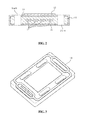
- FIG. 1 is a perspective view of a unit cell for solid-oxide fuel cell according to the present invention.
- FIG. 2 is a cross-sectional view of the unit cell for solid-oxide fuel cell according to the present invention.
- FIG. 3 is a perspective view of the unit cell for a solid-oxide fuel cell according to the present invention which includes a sealing gasket.
- FIG. 4 shows one anode tape which is used in manufacture of the unit cell for a solid-oxide fuel cell according to the present invention.
- FIG. 5 shows another anode tape which is used in manufacture of the unit cell for a solid-oxide fuel cell according to the present invention.
- FIG. 6 is a perspective view showing flows of fuel and air in a fuel cell stack which is manufactured by layering the unit cells for a solid-oxide fuel cell according to the present invention.
- FIG. 7 is a plan view showing flows of fuel and air in the unit cell for a solid-oxide fuel cell according to the present invention.
- FIG. 8 is a cross-sectional view of a solid-oxide fuel cell according to the present invention.
- FIG. 9 is a perspective view of the solid-oxide fuel cell according to the present invention.
- the present invention provides a unit cell for a solid-oxide fuel cell which includes an anode, an electrolyte layer, a cathode and a connector layer, the unit cell comprising: the anode including fuel flow holes formed in marginal regions of both sides thereof from an upper surface to a lower surface thereof; a plurality of fuel flow paths formed in the anode and extending between the fuel flow holes and air flow holes formed in marginal regions of the other both sides of the anode and positioned adjacent to the fuel flow paths; the cathode layered on the electrolyte layer applied on the anode; and the connector layer applied on the lower surface of the anode.
- the solid-oxide fuel cell which is composed of the unit cells, is configured to allow air and fuel to be injected through the lowermost unit cell of the cell stack to thus electricity rather than through lateral surfaces of the cell stack.
- the unit cell for a solid-oxide fuel cell according to the present invention does not need sealing or a housing which are required to enable air or fuel to evenly flow through lateral surfaces of the conventional solid-oxide fuel cell, and a manifold may be provided to the lowermost unit cell to control air flow.
- the cathode is preferably applied on the electrolyte layer applied on an electrolyte layer formed on the anode such that the anode is positioned between the air flow holes.
- Air is introduced into an air flow hole formed in a marginal region of one side of the unit cell to supply oxygen to the cathode, and the remaining air from which the oxygen has been consumed is discharged through an air flow hole formed in a marginal region of the opposite side of the unit cell.
- the sealing gasket functions to isolate the fuel flow hole vertically formed from the air flow hole vertically formed so as to prevent fuel from being mixed with air, thus improving power generation efficiency of the fuel cell.
- the connector layer is preferably made of ceramic.
- a cell stack which is composed of a plurality of unit cells layered one on another, the connector layer functions to connect one unit cell to another unit cell to allow current to flow therebetween.
- a unit cell including a connector layer layered on one side of an anode is coupled to a cathode of another unit cell through the connector layer to form a cell stack.
- a metal connector layer has disadvantages such as corrosion at a high temperature, higher manufacturing costs, and increased weight
- a ceramic connector layer assures no corrosion at high temperature conditions, and reduces both manufacturing costs and weight, thus enabling weight saving of a fuel cell.
- a surface of the connector layer or the cathode is preferably provided with a plurality of protrusions.
- the protrusions provided on a surface of the cathode or a surface of the connector layer formed on the cathode enables oxygen to be efficiently supplied to the cathode thus improving a power generating efficiency.
- the present invention provides a solid-oxide fuel cell which is manufactured by sequentially layering the unit cells for the solid-oxide fuel cell, wherein a plurality of unit cells are layered such that a cathode of one of the unit cells is coupled to a connector layer of another unit cell, air flow holes of the plurality of unit cells are connected to each other to form an air flow passage, and fuel flow holes of a plurality of unit cells are connected to each other to form a fuel flow passage. Furthermore, it is preferable that the plurality of unit cells are layered such that air and fuel are injected into and discharged from the air flow holes and the fuel flow holes of a lowermost unit cell of the plurality of layered unit cells.
- the solid-oxide fuel cell can circulate fuel and air through the air flow hole and the fuel flow hole formed in the lowermost unit cell of the solid-oxide fuel cell thus generating power.
- the present invention does not need sealing at lateral surfaces which enables simplification of manufacture, easy sealing and reduction of manufacturing costs.
- the present invention utilizes a ceramic connector layer as the connector layers without the use of an additional metal connector layer and a cell frame, it is possible to provide a fuel cell having a reduced weight and a smaller size.
- a metal mesh or a ceramic felt is interposed between an anode of a unit cell and a connector layer of another unit cell.
- the metal mesh includes at least one selected from the group consisting of gold, silver, platinum and stainless steel. The metal mesh can reduce a contact resistance between layered unit cells thus improving performance of the fuel cell and can prevent the breakage of the unit cells caused by a load applied to the unit cells.
- the unit cell for a solid-oxide fuel cell according to the present invention may be manufactured by a process of using an extruder or a process of layering anode tapes prepared by tape casting but should not be construed as being limited thereto.
- the process of using an extruder includes the steps of: 1) molding an anode using a ceramic extruder such that a fuel flow hole is formed therein, providing sealing at the opposite ends of the anode, drying the anode and forming a fuel flow hole and an air flow hole in the anode in a vertical manner; 2) coating one side of the anode with a connector layer and coating the other side of the anode with an electrolyte layer; 3) heat-treating the anode; and 4) coating the anode with a cathode with the electrolyte layer disposed therebetween and then heat-treating the resulting anode.
- the process of layering anode tapes includes the steps of 1) subjecting an anode tape prepared by tape casting to laser cutting, ultrasound ablation or machining; 2) layering anode tapes each including only an air flow holes to both sides of the anode tape including only a fuel flow hole formed therein and laminating the layered body while heating the layered body; 3) forming a fuel flow passage in the layered body; 4) coating one side of the resulting anode with a connector layer and coating the other side of the resulting anode with an electrolyte layer; 5) heat-treating the anode; and 5) coating the anode with a cathode with the electrolyte layer disposed therebetween and heat-treating the resulting anode.
- 1 denotes a unit cell for a solid-oxide fuel cell
- 11 denotes an anode
- 12 denotes a cathode
- 14 a and 14 b denote fuel flow holes
- 15 a , 15 b , 15 c , 15 d denote air flow holes
- 16 denotes a connector
- 17 denotes a fuel flow path
- 18 denotes a sealing gasket
- 19 denotes a metal mesh
- 20 denotes a manifold
- 21 denotes a top plate
- 22 denotes a bottom plate.
- a flat anode support 11 that is, an anode 11 is molded using a ceramic extruder such that fuel flow paths 17 are formed therein, and the opposite ends of the anode 11 are sealed. Subsequently, the molded body is vertically formed with fuel inlet and outlet 14 a , 14 b and air inlets and outlets 15 a , 15 b , 15 c , 15 d .
- the bottom surface of the anode 11 is coated with a connector layer 16 .
- the area of a surface of the anode 11 which is not coated with the connector layer 16 is coated with an electrolyte layer 13 , and the anode 11 is heat-treated at a temperature of 1350 to 1400° C.
- the surface of the electrolyte layer 13 which faces away from the connector layer 16 is coated with a cathode 12 and is heat-treated at a temperature of 900 to 1200° C. thus preparing a unit cell for the solid-oxide fuel cell 1 .
- the air flow holes 15 a , 15 b , 15 c , 15 d are vertically formed in marginal regions of both longitudinal sides of the anode 11 with the cathode 12 disposed therebetween.
- the fuel flow holes 14 a , 14 b are vertically formed in marginal regions of both other sides of the anode 11 and communicate with the fuel flow paths 17 to allow fuel to flow therethrough.
- Anode tapes which are prepared through tape casting, are worked using a laser cutting process as illustrated in FIGS. 4 and 5 .
- the anode tape illustrated in FIG. 4 is used as first and third layers and the anode tape illustrated in FIG. 5 is used as a second layer.
- the first to third layers are sequentially layered. Subsequently, the layers are laminated while being heated, and the plurality of fuel flow paths 17 are connected.
- the fuel flow holes 14 a , 14 b are vertically formed in the anode.
- the anode including the fuel flow paths 17 therein is pre-sintered (heat-treated).
- the bottom surface of the anode 11 is coated with the connector layer 16
- the remaining surface of the anode 11 that is not coated with the connector layer 16 is coated with the electrolyte layer 13 .
- the anode is heat-treated at a temperature of 1350 to 1400° C. to densify the connector layer 16 and the electrolyte layer 13 .
- the surface of the electrolyte layer 13 that faces away from the connector layer 16 is coated with a cathode 12 and is heat-treated at a temperature of 900 to 1200° C. thus preparing a unit cell for solid-oxide fuel cell 1 as illustrated in FIG. 1 .
- the prepared unit cell for a solid-oxide fuel cell 1 is provided with a sealing gasket 18 so as to isolate the fuel flow holes 14 a , 14 b from the air flow holes 15 a , 15 b , 15 c , 15 d , thus providing the unit cell for a solid-oxide fuel cell including the seaming gasket.
- FIG. 6 is a perspective view of a solid-oxide fuel cell stack which is manufactured by stacking the unit cells for a solid-oxide fuel cell prepared in Example 3. As illustrated in FIG. 6 , a plurality of unit cells for a solid-oxide fuel cell is layered to provide the solid-oxide fuel cell stack. Fuel and air are injected into a lower surface of a unit cell layered at the lowermost position to create electricity. The injected fuel and air are discharged from the air flow holes and the fuel flow holes positioned at the opposite upper surface.
- FIG. 7 schematically shows the flows of air and fuel.
- FIGS. 8 and 9 are views showing a solid-oxide fuel cell which is manufactured by layering current-collecting plates 21 , 22 on the top and the bottom of the solid-oxide fuel cell stack.
- the current-collecting plate 22 layered on the bottom of the solid-oxide fuel cell stack is connected to a manifold 20 to allow fuel and air to be injected and discharged.
- metal felts or ceramic felts are further provided between the layered unit cells to enhance power generation efficiency of the fuel cell.
- the fuel flow holes and the air flow holes are vertically formed in the anode, there is no need for additional separating plates and additional sealing work for injection and discharge of fuel and air through a lateral surface of the fuel cell, and thus reduction in weight, size, manufacturing costs and the like of the unit cell for a solid-oxide fuel cell is achieved. Therefore, the industrial applicability of the present invention is ensured.
Landscapes
- Engineering & Computer Science (AREA)
- Manufacturing & Machinery (AREA)
- Life Sciences & Earth Sciences (AREA)
- Sustainable Development (AREA)
- Sustainable Energy (AREA)
- Chemical & Material Sciences (AREA)
- Chemical Kinetics & Catalysis (AREA)
- Electrochemistry (AREA)
- General Chemical & Material Sciences (AREA)
- Fuel Cell (AREA)
Applications Claiming Priority (3)
| Application Number | Priority Date | Filing Date | Title |
|---|---|---|---|
| KR10-2012-0019749 | 2012-02-27 | ||
| KR1020120019749A KR101151868B1 (ko) | 2012-02-27 | 2012-02-27 | 고체산화물 연료전지용 단위 셀 및 이를 이용한 고체산화물 연료전지 |
| PCT/KR2013/001087 WO2013129787A1 (ko) | 2012-02-27 | 2013-02-12 | 고체산화물 연료전지용 단위 셀 및 이를 이용한 고체산화물 연료전지 |
Publications (2)
| Publication Number | Publication Date |
|---|---|
| US20150024299A1 US20150024299A1 (en) | 2015-01-22 |
| US9806360B2 true US9806360B2 (en) | 2017-10-31 |
Family
ID=46272761
Family Applications (1)
| Application Number | Title | Priority Date | Filing Date |
|---|---|---|---|
| US14/380,107 Active 2034-09-11 US9806360B2 (en) | 2012-02-27 | 2013-02-12 | Unit cell for solid-oxide fuel cell and solid-oxide fuel cell using same |
Country Status (4)
| Country | Link |
|---|---|
| US (1) | US9806360B2 (ko) |
| JP (1) | JP5908998B2 (ko) |
| KR (1) | KR101151868B1 (ko) |
| WO (1) | WO2013129787A1 (ko) |
Cited By (1)
| Publication number | Priority date | Publication date | Assignee | Title |
|---|---|---|---|---|
| US11870105B2 (en) | 2016-08-16 | 2024-01-09 | Lg Chem, Ltd. | Planar solid oxide fuel cell |
Families Citing this family (7)
| Publication number | Priority date | Publication date | Assignee | Title |
|---|---|---|---|---|
| KR102032233B1 (ko) * | 2013-04-18 | 2019-10-16 | 한국에너지기술연구원 | 매니폴드 일체형 집전체 및 상기 집전체를 포함하는 연료전지 또는 수전해 스택용 하우징 |
| KR101670800B1 (ko) | 2014-08-27 | 2016-10-31 | 한국에너지기술연구원 | 고체산화물 연료전지용 셀 및 그 제조방법 |
| KR102123715B1 (ko) | 2016-08-16 | 2020-06-16 | 주식회사 엘지화학 | 고체 산화물 연료전지 |
| JP6983017B2 (ja) * | 2017-09-15 | 2021-12-17 | 森村Sofcテクノロジー株式会社 | 燃料電池スタック |
| DE102020119020B3 (de) * | 2020-07-17 | 2021-08-12 | kraftwerk TUBES GmbH | Stapelmodulbox in Verbindung mit einer Mehrzahl zu der Stapelmodulbox geführten Medienführungen, Brennstoffzellenvorrichtung sowie Brennstoffzellen-Fahrzeug |
| CN115863724B (zh) * | 2022-12-08 | 2024-05-28 | 北京理工大学 | 一种管式固体氧化物燃料电池集流组堆结构及其实现方法 |
| KR20240150949A (ko) * | 2023-04-10 | 2024-10-17 | 피엔피에너지텍 주식회사 | 매니폴드 |
Citations (10)
| Publication number | Priority date | Publication date | Assignee | Title |
|---|---|---|---|---|
| JPH0676842A (ja) | 1992-08-25 | 1994-03-18 | Mitsubishi Heavy Ind Ltd | 平板型固体電解質燃料電池 |
| JPH07105961A (ja) | 1993-10-12 | 1995-04-21 | Mitsubishi Heavy Ind Ltd | 固体電解質電解セルの製造方法 |
| JP2003331874A (ja) | 2002-05-14 | 2003-11-21 | Nippon Telegr & Teleph Corp <Ntt> | 固体酸化物形燃料電池用インターコネクタおよびその形成方法 |
| KR100538555B1 (ko) | 2003-08-25 | 2005-12-23 | 한국에너지기술연구원 | 연료극 지지체식 평관형 고체산화물 연료전지 스택과 그제조 방법 |
| US20090246598A1 (en) * | 2008-03-27 | 2009-10-01 | Honda Motor Co., Ltd. | Fuel cell system |
| KR100942091B1 (ko) | 2007-11-22 | 2010-02-12 | 주식회사 포스코 | 평판형 고체산화물 연료전지의 적층구조 |
| KR20100072802A (ko) | 2008-12-22 | 2010-07-01 | 한국에너지기술연구원 | 고체 산화물 연료 전지 스택 장치 |
| US20120301815A1 (en) * | 2010-03-17 | 2012-11-29 | Honda Motor Co., Ltd. | Fuel cell |
| US20130280633A1 (en) * | 2010-12-28 | 2013-10-24 | Posco | Fuel Cell System and Stack |
| US20140147771A1 (en) * | 2011-07-13 | 2014-05-29 | Teknologisk Institut | Fuel cell, a portable electronic device and a method of manufacturing a fuel cell reservoir |
Family Cites Families (8)
| Publication number | Priority date | Publication date | Assignee | Title |
|---|---|---|---|---|
| JPH04272661A (ja) * | 1991-02-27 | 1992-09-29 | Yuasa Corp | 固体電解質燃料電池装置 |
| JPH04272662A (ja) * | 1991-02-27 | 1992-09-29 | Yuasa Corp | 固体電解質燃料電池装置 |
| GB9403234D0 (en) * | 1994-02-19 | 1994-04-13 | Rolls Royce Plc | A solid oxide fuel cell stack and a reactant distribution member therefor |
| US20070141424A1 (en) * | 2005-12-21 | 2007-06-21 | Armstrong Timothy R | Solid oxide fuel cell and stack configuration |
| KR101109294B1 (ko) * | 2009-07-13 | 2012-01-31 | 삼성전기주식회사 | 일체형지지체를 갖는 연료전지 |
| KR101109222B1 (ko) * | 2009-08-05 | 2012-01-30 | 삼성전기주식회사 | 일체형지지체를 구비한 연료전지 스택 |
| KR101119396B1 (ko) * | 2009-08-31 | 2012-03-06 | 삼성전기주식회사 | 고체 산화물 연료전지 구조 |
| JP5331252B2 (ja) * | 2010-07-30 | 2013-10-30 | コリア インスティチュート オブ エナジー リサーチ | 平管型固体酸化物セルスタック |
-
2012
- 2012-02-27 KR KR1020120019749A patent/KR101151868B1/ko not_active Expired - Fee Related
-
2013
- 2013-02-12 US US14/380,107 patent/US9806360B2/en active Active
- 2013-02-12 JP JP2014558667A patent/JP5908998B2/ja active Active
- 2013-02-12 WO PCT/KR2013/001087 patent/WO2013129787A1/ko not_active Ceased
Patent Citations (10)
| Publication number | Priority date | Publication date | Assignee | Title |
|---|---|---|---|---|
| JPH0676842A (ja) | 1992-08-25 | 1994-03-18 | Mitsubishi Heavy Ind Ltd | 平板型固体電解質燃料電池 |
| JPH07105961A (ja) | 1993-10-12 | 1995-04-21 | Mitsubishi Heavy Ind Ltd | 固体電解質電解セルの製造方法 |
| JP2003331874A (ja) | 2002-05-14 | 2003-11-21 | Nippon Telegr & Teleph Corp <Ntt> | 固体酸化物形燃料電池用インターコネクタおよびその形成方法 |
| KR100538555B1 (ko) | 2003-08-25 | 2005-12-23 | 한국에너지기술연구원 | 연료극 지지체식 평관형 고체산화물 연료전지 스택과 그제조 방법 |
| KR100942091B1 (ko) | 2007-11-22 | 2010-02-12 | 주식회사 포스코 | 평판형 고체산화물 연료전지의 적층구조 |
| US20090246598A1 (en) * | 2008-03-27 | 2009-10-01 | Honda Motor Co., Ltd. | Fuel cell system |
| KR20100072802A (ko) | 2008-12-22 | 2010-07-01 | 한국에너지기술연구원 | 고체 산화물 연료 전지 스택 장치 |
| US20120301815A1 (en) * | 2010-03-17 | 2012-11-29 | Honda Motor Co., Ltd. | Fuel cell |
| US20130280633A1 (en) * | 2010-12-28 | 2013-10-24 | Posco | Fuel Cell System and Stack |
| US20140147771A1 (en) * | 2011-07-13 | 2014-05-29 | Teknologisk Institut | Fuel cell, a portable electronic device and a method of manufacturing a fuel cell reservoir |
Cited By (1)
| Publication number | Priority date | Publication date | Assignee | Title |
|---|---|---|---|---|
| US11870105B2 (en) | 2016-08-16 | 2024-01-09 | Lg Chem, Ltd. | Planar solid oxide fuel cell |
Also Published As
| Publication number | Publication date |
|---|---|
| US20150024299A1 (en) | 2015-01-22 |
| JP5908998B2 (ja) | 2016-04-26 |
| KR101151868B1 (ko) | 2012-05-31 |
| WO2013129787A1 (ko) | 2013-09-06 |
| JP2015511755A (ja) | 2015-04-20 |
Similar Documents
| Publication | Publication Date | Title |
|---|---|---|
| US9806360B2 (en) | Unit cell for solid-oxide fuel cell and solid-oxide fuel cell using same | |
| USRE41577E1 (en) | High power density fuel cell stack using micro structured components | |
| CN101335358B (zh) | 燃料电池 | |
| JP5240282B2 (ja) | 燃料電池セル | |
| JP5123279B2 (ja) | 燃料電池 | |
| JP2006506795A (ja) | 膜ベース電気化学電池スタック | |
| KR20170117189A (ko) | 전기 화학 반응 단위 및 연료 전지 스택 | |
| JP2004087311A (ja) | 燃料電池スタックおよび燃料電池スタック用金属製セパレータ | |
| KR20150074283A (ko) | 고체산화물 연료전지용 분리판, 이를 포함하는 고체산화물 연료전지 및 그 제조방법 | |
| JP2013145653A (ja) | 燃料電池用樹脂枠付き電解質膜・電極構造体 | |
| JP6434299B2 (ja) | セルスタック、モジュールおよびモジュール収容装置 | |
| CA2608616C (en) | Fuel cell with simplified separator structure | |
| US20120052410A1 (en) | High-Volume-Manufacture Fuel Cell Arrangement and Method for Production Thereof | |
| CN107579262B (zh) | 一种平板型固体氧化物燃料电池连接部件及其应用 | |
| JP5297990B2 (ja) | 燃料電池 | |
| WO2006085172A2 (en) | Fuel cell separator | |
| JP7023898B2 (ja) | 電気化学反応セルスタック | |
| KR100546016B1 (ko) | 연료전지용 전류집전체와 그 제조방법, 그리고 이를구비한 연료전지 | |
| KR101174407B1 (ko) | 고체전해질 연료전지의 제조방법 | |
| JP5583824B2 (ja) | 燃料電池 | |
| US11271221B2 (en) | Electrochemical reaction cell stack, interconnector-electrochemical reaction unit cell composite, and method for manufacturing electrochemical reaction cell stack | |
| KR101301824B1 (ko) | 연료 전지용 분리판 | |
| JP6898188B2 (ja) | 燃料電池スタック | |
| WO2007043368A1 (ja) | 燃料電池およびその製造方法 | |
| JP2004055296A (ja) | 燃料電池のセパレータ、発電セル及び燃料電池 |
Legal Events
| Date | Code | Title | Description |
|---|---|---|---|
| AS | Assignment |
Owner name: KOREA INSTITUTE OF ENERGY RESEARCH, KOREA, REPUBLI Free format text: ASSIGNMENT OF ASSIGNORS INTEREST;ASSIGNORS:YU, JI-HAENG;HAN, IN-SUB;SEO, DOO-WON;AND OTHERS;REEL/FRAME:033579/0556 Effective date: 20140808 |
|
| STCF | Information on status: patent grant |
Free format text: PATENTED CASE |
|
| MAFP | Maintenance fee payment |
Free format text: PAYMENT OF MAINTENANCE FEE, 4TH YR, SMALL ENTITY (ORIGINAL EVENT CODE: M2551); ENTITY STATUS OF PATENT OWNER: SMALL ENTITY Year of fee payment: 4 |
|
| MAFP | Maintenance fee payment |
Free format text: PAYMENT OF MAINTENANCE FEE, 8TH YR, SMALL ENTITY (ORIGINAL EVENT CODE: M2552); ENTITY STATUS OF PATENT OWNER: SMALL ENTITY Year of fee payment: 8 |